EP1985730B1 - Method for measuring the weight of fibre sliver and device to perform the method - Google Patents
Method for measuring the weight of fibre sliver and device to perform the method Download PDFInfo
- Publication number
- EP1985730B1 EP1985730B1 EP08466008.3A EP08466008A EP1985730B1 EP 1985730 B1 EP1985730 B1 EP 1985730B1 EP 08466008 A EP08466008 A EP 08466008A EP 1985730 B1 EP1985730 B1 EP 1985730B1
- Authority
- EP
- European Patent Office
- Prior art keywords
- pressing roller
- fibre sliver
- longitudinal axis
- drawing rollers
- weight
- Prior art date
- Legal status (The legal status is an assumption and is not a legal conclusion. Google has not performed a legal analysis and makes no representation as to the accuracy of the status listed.)
- Not-in-force
Links
- 239000000835 fiber Substances 0.000 title claims 8
- 238000000034 method Methods 0.000 title claims 5
- 238000012544 monitoring process Methods 0.000 claims 1
Images


Classifications
-
- D—TEXTILES; PAPER
- D01—NATURAL OR MAN-MADE THREADS OR FIBRES; SPINNING
- D01H—SPINNING OR TWISTING
- D01H13/00—Other common constructional features, details or accessories
- D01H13/14—Warning or safety devices, e.g. automatic fault detectors, stop motions ; Monitoring the entanglement of slivers in drafting arrangements
- D01H13/22—Warning or safety devices, e.g. automatic fault detectors, stop motions ; Monitoring the entanglement of slivers in drafting arrangements responsive to presence of irregularities in running material
-
- D—TEXTILES; PAPER
- D01—NATURAL OR MAN-MADE THREADS OR FIBRES; SPINNING
- D01H—SPINNING OR TWISTING
- D01H5/00—Drafting machines or arrangements ; Threading of roving into drafting machine
- D01H5/18—Drafting machines or arrangements without fallers or like pinned bars
- D01H5/32—Regulating or varying draft
- D01H5/38—Regulating or varying draft in response to irregularities in material ; Measuring irregularities
Definitions
- the invention relates to the method for measuring the weight of fibre sliver through monitoring the quantum of fibres in the fibre sliver passing through the defined space between a pair of drawing rollers out of which one is a pressing roller, in which by passing fibre sliver through a defined space between a pair of drawing rollers, the longitudinal axis of pressing roller is deflected in a plane passing through longitudinal axes of the drawing rollers, and in this plane or in the plane parallel with it is sensed deflection of longitudinal axis of the pressing roller in at least one point, whereas the rate of deflection of longitudinal axis of the pressing roller is proportionate to the weight of fibre sliver.
- the invention also relates to the device for measuring the weight of fibre sliver comprising a pair of drawing rollers, out of which one is a pressing roller, and the pair of drawing rollers is equipped with space for passage of fibre sliver through, while pressing roller is in the frame of the device mounted deflectable by its longitudinal axis in the plane passing the longitudinal axes of the drawing rollers, whereas to the assembly of the pressing roller there is assigned a sensor of the change in position of longitudinal axis of the pressing roller.
- the sliver weight is given by its volume.
- the sliver volume is measured, e.g. by sensing the sliver by means of the stow-away arm in condenser or other defined space.
- the stow-away arm is coupled with electronic sensor that measures deflection of the stow-away arm. Behind the assembly of stow-away arm and electronic sensor there is arranged the drawing-off device which draws the fibre sliver through the measuring device.
- Known is also method for measuring the weight of fibre sliver which is based on a change of optical properties of fibre sliver in dependence on a change in weight. If the fibre sliver is illuminated e.g. by infrared light, the intensity of passing through light may be measured, and this is changed in dependence on weight of fibre sliver. For this measurement to be sufficiently precise, the space for fibre sliver must be so small, so that the whole cross-section of fibres is monitored by the passing through light. This provides resistance to the fibre sliver, and therefore behind this optical sensor, in its immediate vicinity, there must be drawing off device. Guidance of fibre sliver into this optical sensor is difficult.
- the value of the deflection is proportionate to the weight of fibre sliver.
- a pair of rollers is rotatably mounted in bearings, one of the rollers of each pair in its middle section is provided with a disk with recess, into which engages the disk performed on the second roller.
- the pair of rollers is coupled with the drive so, that one of the rollers is coupled with gear wheels with motor, and the second roller is coupled with it e.g. by a tooth wheel.
- the driven roller from the pair of rollers is mounted so that, its longitudinal axis does not change its position during operation of the device.
- the pressing roller of the pair of rollers is by a pressing force, e.g. by means of a spring or ballast weight or in a pneumatic manner etc., held in working position and against this force there acts the pressure of fibre sliver in guiding means (between the discs) on rollers.
- the main disadvantage of this method is that, the position of longitudinal axis of pressing roller of the pair of rollers is always parallel with axis of the roller, which is only rotatable.
- the press roller may not be driven by friction of pulleys, but e.g. by tooth wheels. These wheels are close to the moving fibres and therefore the toothing is clogged with flying-off fibres.
- the changing distance is also not good for a correct position of the side of teeth of toothing.
- the goal of the invention is to find such method for measuring the weight of fibre sliver which would provide sufficiently precise information for controlling and regulation of weight of fibre sliver and which would not impair serviceability of the drawing device.
- the goal of the invention has been reached by the method for measuring the weight of fibre sliver whose principle consists in that longitudinal axis of the pressing roller is swinging around a single point in the plane passing the longitudinal axes of drawing rollers or in the plane parallel with it and the change in position of longitudinal axis of the pressing roller during swinging around a single point in the plane passing the longitudinal axes of drawing rollers or in the plane parallel with it is sensed.
- This method for measuring the weight of fibre sliver enables measuring directly on each pair of rollers in the drawing device. With advantage this principle is applied on the outlet pair of rollers from the drawing device.
- the final status of fibre sliver and information on its real weight can be utilised in the regulation system for a feedback adjusting of the weight of fibre sliver. Realisation of this measuring method of fibre sliver weight does not have any negative impact on serviceability of the drawing device. There is also no negative impact on transfer of torque from the driving roller to the pressing roller.
- the principle of the device for measuring the weight of fibre sliver consists in that the pressing roller is in the frame of the device mounted swingably around the single point in the plane passing the longitudinal axes of drawing rollers or in the plane parallel with it.
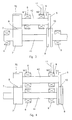
- the invention is schematically represented in the drawings, where the Fig. 1 shows the pair of drawing rollers in operation position with contactless sensor of position of pressing pulley, the Fig. 2 shows embodiment with pressing roller position sensor, which touches its surface, the Fig. 3 shows another mounting of pressing shaft and the contact sensor of pressing roller position, the Fig. 4 shows another embodiment of mounting of the pressing roller and positioning of the sensor of pressing roller position.
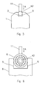
- the Fig. 5 and Fig. 6 show methods for mounting of drawing rollers so, that their swinging motion corresponds to the weight of fibre sliver and is in the sensed plane.
- the method for measuring the weight of fibre sliver will be described on exemplary embodiments of several variants of the device for measuring the weight of fibre sliver.
- the device for measuring the weight of fibre sliver in the represented embodiments comprises a pair in principle parallel drawing rollers, which are rotatably mounted in bearings 6 and which are mutually coupled in their drive, e.g. by the friction gear 7 realised by a pair of collars 70 and 71 on each of drawing rollers.
- One from the pair of drawing rollers is only a rotating roller 41 and the second from the pair of drawing rollers is the pressing roller 42 .
- One from the pair of drawing rollers is provided with the disc 8 with recess, into which there extends the disc 9 positioned on the second from the pair of drawing rollers.
- the disc 9 does not sit down as far as the bottom of the recess in the disc 8 , by which there is performed a space 10 for passage of the not represented fibre sliver. Only the rotating roller 41 is coupled with the not represented drive and the pressing roller 42 is to the only rotating roller 41 pressed by forces N 1 and N 2 . This pressure ensures transfer of the torque from the only rotating roller 41 to the pressing roller 42 .
- the only rotating roller 41 has a stable position of its longitudinal axis, i.e. the axis of its rotation, in bearings 6
- the pressing roller 42 is mounted with a variable position of its longitudinal axis in the plane passing through the longitudinal axes of drawing rollers or in the plane being parallel with it.
- Variability of position of the longitudinal axis of the press roller 42 is given in dependence on the magnitude of pressure forces N 1 a N 2 and on the magnitude of force from the fibre sliver, i.e. the force, which is generated upon pressing the fibre sliver in the space 10 .
- the device is further provided with a measuring device of variability of position of the longitudinal axis of the pressing roller 42 in the plane passing through longitudinal axes of drawing rollers or in a plane being parallel with it.
- the pair of drawing rollers is coupled in their drive with a pair of friction gears 7 .
- the space 10 for guiding of fibre sliver is situated in the middle of a pair of friction gears 7.
- the measuring device for measuring the variability of position of longitudinal axis of the pressing roller 42 in the plane passing through the longitudinal axes of the drawing rollers or in a plane parallel with it, i.e. in the direction A , there is used the measuring device with the contactless sensor 16 , which is assigned to the disc 9 , which in dependence on the weight of fibres sliver squeezed in the space 10 is deflected only in the plane passing through the longitudinal axes of the drawing rollers or in the plane parallel with it, through which its position is changed and the sensor 16 senses this change of position.
- the contact sensor In this example of embodiment it is difficult to use the contact sensor because the disc 9 in part is rotating, which would cause friction abrasion of contact surfaces of the sensor and of the disc 9 , and in part the size of change in position of longitudinal axis of the pressing roller 42 outside the disc 9 is variable in dependence on that, whether the press roller lifts or lowers symmetrically or swings around some of both points B1 or B2 .
- the Fig. 2 represents embodiment at which the contact sensor 11 touches the non-rotating sections of assembly of the pressing roller 42 , which is subject to acting of pressing forces N 2 ⁇ N 1 .
- the space 10 for guiding the fibre sliver is positioned asymmetrically towards the friction gear 7 . Swinging of the pressing roller 42 in the plane passing through the longitudinal axes of drawing rollers or in the plane parallel with it, i.e. in the direction A , realises always around one single point B , which is on surface of the friction collars 70 , 71 or in its close vicinity.
- the pair of drawing rollers is coupled with only one friction gear 7 .
- the disc 9 which engages into the recess of the disc 8 , is positioned on one end of the pressing roller 42 and the friction gear 7 is positioned on the second end of the pressing roller 42 .
- the pressing roller 42 is rotatably in bearings 6 mounted between the disc 9 and the friction gear 7 .
- the friction gear 7 and the disc 3 with recess are situated between the bearings 6 .
- the correct rate of size of the pressing forces N 1 and N 2 is not required and it is possible to use the contact sensor 11 of position of the pressing roller 42 .
- this contact sensor 11 is positioned against outer ring of the bearing 6 near to the disc 9 .
- the motion of the pressing roller 42 is in the plane passing the longitudinal axes of drawing rollers or in the plane parallel with it, i.e. in the direction A , around the point B .
- the disc 8 with recess is situated on the free end of the only rotating roller 41 as far as behind the bearing 6 and the friction gear 7 is positioned on the second end of only rotating roller 41 as far as behind the bearing 6 .
- Sensing of motion of the pressing roller 42 is similar as at embodiment in the Fig. 3 , this by means of the contact sensor 11 assigned to the outer ring of the bearing 6 closer to the disc 9 .
- This provision consists in that a part of the frame 1 of the drawing device, in which the drawing rollers are positioned, is provided with recess with a pair of guiding surfaces 3 , while in the recess there is situated the end of the pressing roller 42 , which by the guiding surfaces 3 of the recess is guided so that possible is only its deflecting in the plane passing through longitudinal axes of drawing rollers or in the plane parallel with it, i.e. in the direction A , in which the sensor 11 is set.
- FIG. 6 there is represented another possible provision to additional securing of deflection of the pressing roller 42 in the plane passing through longitudinal axes of drawing rollers or in the plane parallel with it, i.e. in the direction A .
- This provision consists in that a part of the frame 1 of the drawing device, in which the drawing rollers are positioned, is provided with recess with a pair of guiding surfaces 5 , while in the recess there is situated the bearing 6 on the pressing roller 42 , which by this recess is guided so that deflection of the pressing roller 42 is possible in the plane passing through longitudinal axes of drawing rollers or in the plane parallel with it, i.e. in the direction A in which the sensor 11 is set.
- the pair of drawing rollers is arranged so that the disc 8 is arranged on only rotating roller 41 and the disc with recess 9 is arranged on the pressing roller 42 .
- the common feature of exemplary embodiments illustrating this invention is that the individual functional elements are arranged so that, besides the rotating motion of both drawing rollers there is enabled also deflecting of one of them in the plane passing through the longitudinal axes of drawing rollers or in the plane parallel with it. At the same time the rate of deflection of the longitudinal axis of this drawing roller is measured, which corresponds to the weight of fibre sliver.
- the invention is applicable in textile technique.
Landscapes
- Engineering & Computer Science (AREA)
- Mechanical Engineering (AREA)
- Textile Engineering (AREA)
- Spinning Or Twisting Of Yarns (AREA)
- Preliminary Treatment Of Fibers (AREA)
Description
- The invention relates to the method for measuring the weight of fibre sliver through monitoring the quantum of fibres in the fibre sliver passing through the defined space between a pair of drawing rollers out of which one is a pressing roller, in which by passing fibre sliver through a defined space between a pair of drawing rollers, the longitudinal axis of pressing roller is deflected in a plane passing through longitudinal axes of the drawing rollers, and in this plane or in the plane parallel with it is sensed deflection of longitudinal axis of the pressing roller in at least one point, whereas the rate of deflection of longitudinal axis of the pressing roller is proportionate to the weight of fibre sliver.
- The invention also relates to the device for measuring the weight of fibre sliver comprising a pair of drawing rollers, out of which one is a pressing roller, and the pair of drawing rollers is equipped with space for passage of fibre sliver through, while pressing roller is in the frame of the device mounted deflectable by its longitudinal axis in the plane passing the longitudinal axes of the drawing rollers, whereas to the assembly of the pressing roller there is assigned a sensor of the change in position of longitudinal axis of the pressing roller.
- At present several principles are known for measuring the weight of fibre slivers. Some principles are based on that the sliver weight is given by its volume. Thus the sliver volume is measured, e.g. by sensing the sliver by means of the stow-away arm in condenser or other defined space. The stow-away arm is coupled with electronic sensor that measures deflection of the stow-away arm. Behind the assembly of stow-away arm and electronic sensor there is arranged the drawing-off device which draws the fibre sliver through the measuring device.
- Further there is known the principle for measuring the weight of fibre sliver based on a change of dielectric capacitance of material. The fibre sliver passes between the plates of condenser, at the same time if the weight of fibre sliver changes, also the dielectric capacitance is changed and together with it also the condenser capacity is changed in dependence on change of fibre sliver weight.
- Known is also method for measuring the weight of fibre sliver which is based on a change of optical properties of fibre sliver in dependence on a change in weight. If the fibre sliver is illuminated e.g. by infrared light, the intensity of passing through light may be measured, and this is changed in dependence on weight of fibre sliver. For this measurement to be sufficiently precise, the space for fibre sliver must be so small, so that the whole cross-section of fibres is monitored by the passing through light. This provides resistance to the fibre sliver, and therefore behind this optical sensor, in its immediate vicinity, there must be drawing off device. Guidance of fibre sliver into this optical sensor is difficult.
- Further there is known a method for weight measuring of fibre sliver, whose principle consists in that the fibre sliver passing the small opening generates a force in the direction of fibre sliver motion, whereas magnitude of the generated force is adequate to the rate of condensing of the fibre sliver in opening. The rate of condensing is given by number of fibres entering the opening, thus being directly dependent on the weight of fibre sliver. By such acquired force in the direction of motion of fibre sliver is loaded the measuring beam, whose deformation, e.g. by means of resistance tensiometers, is measured and through this also the weight of fibre sliver is measured indirectly. Also this method for measuring of weight of fibre sliver requires drawing-off device of fibre sliver behind the sensor in its immediate vicinity. Measuring using this principle cannot be applied in cases, where it is not possible to reliably introduce the tip of fibre sliver into the opening of condenser and to perform drawing-off immediately by the machine.
- Known is also the pneumatic method for measuring of fibre sliver. The fibre sliver is passing through a special chamber, into which a compressed air is brought. Inlet and outlet opening of the chamber are tightened by means of the fibre sliver just passing. With change in weight of fibre sliver also the rate of tightening of chamber openings is changing and simultaneously is changing air pressure in the chamber. The change of air pressure corresponds to the change of weight of fibre sliver. It is measured by means of pressure gauge. This method for measuring the weight of fibre sliver is disadvantageous in that, the measured value represents only an average weight of fibre sliver in relatively long length and this information can not be used into the control system for weight regulation in short sections of fibre sliver.
- Known is also method for measuring the weight of fibre sliver represented in the
Fig. 0 , at which there is sensed deflection of the press roller around the BT rotation axis, which is parallel with axis of rotation of the pressing roller, i.e. in the plane, which is perpendicular to the rotation axis of the pressing roller. The value of the deflection is proportionate to the weight of fibre sliver. In practice utilised device applying this method is constructed so that a pair of rollers is rotatably mounted in bearings, one of the rollers of each pair in its middle section is provided with a disk with recess, into which engages the disk performed on the second roller. The space delimited by sides and bottom of the recess on one roller and by a face surface of the disk on the second roller delimits the space for passage of fibre sliver. The pair of rollers is coupled with the drive so, that one of the rollers is coupled with gear wheels with motor, and the second roller is coupled with it e.g. by a tooth wheel. The driven roller from the pair of rollers is mounted so that, its longitudinal axis does not change its position during operation of the device. The pressing roller of the pair of rollers is by a pressing force, e.g. by means of a spring or ballast weight or in a pneumatic manner etc., held in working position and against this force there acts the pressure of fibre sliver in guiding means (between the discs) on rollers. The main disadvantage of this method is that, the position of longitudinal axis of pressing roller of the pair of rollers is always parallel with axis of the roller, which is only rotatable. This results in that the press roller may not be driven by friction of pulleys, but e.g. by tooth wheels. These wheels are close to the moving fibres and therefore the toothing is clogged with flying-off fibres. The changing distance is also not good for a correct position of the side of teeth of toothing. This solution is described inDE 10 2005 023 992pressing roller 42 might swing or deflect randomly to both sides it considerably increase demands for definiteness determination of change in position of longitudinal axis of thepressing roller 42 on the first or the second side of the measuring space for sliver, and thus is necessary to measure in two places. - The goal of the invention is to find such method for measuring the weight of fibre sliver which would provide sufficiently precise information for controlling and regulation of weight of fibre sliver and which would not impair serviceability of the drawing device.
- The goal of the invention has been reached by the method for measuring the weight of fibre sliver whose principle consists in that longitudinal axis of the pressing roller is swinging around a single point in the plane passing the longitudinal axes of drawing rollers or in the plane parallel with it and the change in position of longitudinal axis of the pressing roller during swinging around a single point in the plane passing the longitudinal axes of drawing rollers or in the plane parallel with it is sensed.
- This method for measuring the weight of fibre sliver enables measuring directly on each pair of rollers in the drawing device. With advantage this principle is applied on the outlet pair of rollers from the drawing device. Here, the final status of fibre sliver and information on its real weight can be utilised in the regulation system for a feedback adjusting of the weight of fibre sliver. Realisation of this measuring method of fibre sliver weight does not have any negative impact on serviceability of the drawing device. There is also no negative impact on transfer of torque from the driving roller to the pressing roller.
- The principle of the device for measuring the weight of fibre sliver consists in that the pressing roller is in the frame of the device mounted swingably around the single point in the plane passing the longitudinal axes of drawing rollers or in the plane parallel with it.
- The preferred embodiments of the method as well as the device are described in description of exemplary embodiments and in dependent claims.
- The invention is schematically represented in the drawings, where the
Fig. 1 shows the pair of drawing rollers in operation position with contactless sensor of position of pressing pulley, theFig. 2 shows embodiment with pressing roller position sensor, which touches its surface, theFig. 3 shows another mounting of pressing shaft and the contact sensor of pressing roller position, theFig. 4 shows another embodiment of mounting of the pressing roller and positioning of the sensor of pressing roller position. TheFig. 5 and Fig. 6 show methods for mounting of drawing rollers so, that their swinging motion corresponds to the weight of fibre sliver and is in the sensed plane. - The method for measuring the weight of fibre sliver will be described on exemplary embodiments of several variants of the device for measuring the weight of fibre sliver.
- The device for measuring the weight of fibre sliver in the represented embodiments comprises a pair in principle parallel drawing rollers, which are rotatably mounted in
bearings 6 and which are mutually coupled in their drive, e.g. by thefriction gear 7 realised by a pair ofcollars roller 41 and the second from the pair of drawing rollers is thepressing roller 42 . One from the pair of drawing rollers is provided with thedisc 8 with recess, into which there extends thedisc 9 positioned on the second from the pair of drawing rollers. Thedisc 9 does not sit down as far as the bottom of the recess in thedisc 8 , by which there is performed aspace 10 for passage of the not represented fibre sliver. Only the rotatingroller 41 is coupled with the not represented drive and thepressing roller 42 is to the only rotatingroller 41 pressed by forces N 1 and N 2 . This pressure ensures transfer of the torque from the only rotatingroller 41 to thepressing roller 42 . - The only rotating
roller 41 has a stable position of its longitudinal axis, i.e. the axis of its rotation, inbearings 6 , while thepressing roller 42 is mounted with a variable position of its longitudinal axis in the plane passing through the longitudinal axes of drawing rollers or in the plane being parallel with it. Variability of position of the longitudinal axis of thepress roller 42 is given in dependence on the magnitude of pressure forces N 1 a N2 and on the magnitude of force from the fibre sliver, i.e. the force, which is generated upon pressing the fibre sliver in thespace 10 . - The device is further provided with a measuring device of variability of position of the longitudinal axis of the
pressing roller 42 in the plane passing through longitudinal axes of drawing rollers or in a plane being parallel with it. - In example of embodiment represented in the
Fig. 1 the pair of drawing rollers is coupled in their drive with a pair of friction gears 7. Thespace 10 for guiding of fibre sliver is situated in the middle of a pair of friction gears 7. In a case that N1 = N 2 the structural arrangement aims to that, the variability in position of longitudinal axis of thepressing roller 42 in the plane passing through longitudinal axes of the drawing rollers or in a plane parallel with it, is demonstrated by deflecting in the direction A without a stabile centre of oscillation in one point, because deflecting may occur either by a symmetric lifting and lowering of thepressing roller 42 or by swinging in principle at random around the point of swinging B1 and B2 . In example of embodiment in theFig. 1 for measuring the variability of position of longitudinal axis of thepressing roller 42 in the plane passing through the longitudinal axes of the drawing rollers or in a plane parallel with it, i.e. in the direction A , there is used the measuring device with thecontactless sensor 16 , which is assigned to thedisc 9 , which in dependence on the weight of fibres sliver squeezed in thespace 10 is deflected only in the plane passing through the longitudinal axes of the drawing rollers or in the plane parallel with it, through which its position is changed and thesensor 16 senses this change of position. In this example of embodiment it is difficult to use the contact sensor because thedisc 9 in part is rotating, which would cause friction abrasion of contact surfaces of the sensor and of thedisc 9 , and in part the size of change in position of longitudinal axis of thepressing roller 42 outside thedisc 9 is variable in dependence on that, whether the press roller lifts or lowers symmetrically or swings around some of both points B1 or B2 . - Accidentality of motion of longitudinal axis of the
pressing roller 42 in the plane passing through the longitudinal axes of the drawing rollers or in the plane parallel to it in embodiment according to theFig. 1 may be eliminated by an arrangement at which N 1 ≠ N 2 This arrangement is characterised in that the longitudinal axis, i.e. the rotation axis of thepressing roller 42 always swings only in the direction A around one of the points B1 or B2 from theFig. 1 , and thus thecontact sensor 11 may be used on the suitable non-rotating section of assembly of thepressing roller 42. - Accidentality of motion of longitudinal axis of the
pressing roller 42 in the plane passing through the longitudinal axes of the drawing rollers or in the plane parallel to it may also be eliminated through asymmetric arrangement of thespace 10 for guiding the fibre sliver towards thefriction gear 7 of thepressing roller 42 . This arrangement is also characterised in that the longitudinal axis of thepressing roller 42 always swings only in the plane passing through longitudinal axes of drawing rollers or in the plane parallel with it, i.e. in the direction A , around one of the points B1 or B2 from theFig. 1 , and thus thecontact sensor 11 may be used on the suitable non-rotating section of assembly of thepressing roller 42 . At this arrangement there is then possible both the embodiment in which N 1 ≠ N 2 , and the embodiment in which N 1 = N 2 . - The
Fig. 2 represents embodiment at which thecontact sensor 11 touches the non-rotating sections of assembly of thepressing roller 42 , which is subject to acting of pressing forces N 2 ≤ N 1 . In this example of embodiment thespace 10 for guiding the fibre sliver is positioned asymmetrically towards thefriction gear 7 . Swinging of thepressing roller 42 in the plane passing through the longitudinal axes of drawing rollers or in the plane parallel with it, i.e. in the direction A , realises always around one single point B, which is on surface of thefriction collars - In exemplary embodiment represented in the
Fig. 3 the pair of drawing rollers is coupled with only onefriction gear 7 . Thedisc 9 , which engages into the recess of thedisc 8 , is positioned on one end of thepressing roller 42 and thefriction gear 7 is positioned on the second end of thepressing roller 42 . Thepressing roller 42 is rotatably inbearings 6 mounted between thedisc 9 and thefriction gear 7 . On the onlyrotating roller 41 , thefriction gear 7 and thedisc 3 with recess are situated between thebearings 6 . At embodiment according to theFig. 3 the correct rate of size of the pressing forces N 1 and N 2 is not required and it is possible to use thecontact sensor 11 of position of thepressing roller 42 . Preferably thiscontact sensor 11 is positioned against outer ring of thebearing 6 near to thedisc 9 . Also here the motion of thepressing roller 42 , respectively of its longitudinal axis, is in the plane passing the longitudinal axes of drawing rollers or in the plane parallel with it, i.e. in the direction A , around the point B . - In exemplary embodiment represented in the
Fig. 4 , that represents modified embodiment according to theFig. 3 , thedisc 8 with recess is situated on the free end of the onlyrotating roller 41 as far as behind thebearing 6 and thefriction gear 7 is positioned on the second end of only rotatingroller 41 as far as behind thebearing 6 . Sensing of motion of thepressing roller 42 , respectively of its longitudinal axis, in the plane passing through longitudinal axes of drawing rollers or in the plane parallel with it, i.e. in the direction A , is similar as at embodiment in theFig. 3 , this by means of thecontact sensor 11 assigned to the outer ring of thebearing 6 closer to thedisc 9 . - In exemplary embodiment represented in the
Fig. 5 there is represented a possible provision to additional securing of deflection of thepressing roller 42 in the plane passing through the longitudinal axes of drawing rollers or in the plane parallel with it, i.e. in the direction A . This provision consists in that a part of theframe 1 of the drawing device, in which the drawing rollers are positioned, is provided with recess with a pair of guidingsurfaces 3 , while in the recess there is situated the end of thepressing roller 42 , which by the guidingsurfaces 3 of the recess is guided so that possible is only its deflecting in the plane passing through longitudinal axes of drawing rollers or in the plane parallel with it, i.e. in the direction A , in which thesensor 11 is set. - In exemplary embodiment represented in the
Fig. 6 there is represented another possible provision to additional securing of deflection of thepressing roller 42 in the plane passing through longitudinal axes of drawing rollers or in the plane parallel with it, i.e. in the direction A . This provision consists in that a part of theframe 1 of the drawing device, in which the drawing rollers are positioned, is provided with recess with a pair of guidingsurfaces 5 , while in the recess there is situated thebearing 6 on thepressing roller 42, which by this recess is guided so that deflection of thepressing roller 42 is possible in the plane passing through longitudinal axes of drawing rollers or in the plane parallel with it, i.e. in the direction A in which thesensor 11 is set. - In another not represented example of embodiment the pair of drawing rollers is arranged so that the
disc 8 is arranged on only rotatingroller 41 and the disc withrecess 9 is arranged on thepressing roller 42 . - The common feature of exemplary embodiments illustrating this invention is that the individual functional elements are arranged so that, besides the rotating motion of both drawing rollers there is enabled also deflecting of one of them in the plane passing through the longitudinal axes of drawing rollers or in the plane parallel with it. At the same time the rate of deflection of the longitudinal axis of this drawing roller is measured, which corresponds to the weight of fibre sliver.
- The invention is not limited to embodiments here expressly mentioned and described, because modification of principles according to this invention for particular structural solution, including the possible combinations of individual structural features, does not exceed limits of this invention either the scope of mere professional skills.
- The invention is applicable in textile technique.
Claims (7)
- A method for measuring the weight of fibre sliver through monitoring the quantum of fibres in the fibre sliver passing through the defined space between a pair of drawing rollers (41,42) out of which one is a pressing roller (42), in which by passing fibre sliver through a defined space (10) between a pair of drawing rollers (41,42), the longitudinal axis of pressing roller (42) is deflected in a plane passing through longitudinal axes of the drawing rollers (41,42), and in this plane or in the plane parallel with it is sensed deflection of longitudinal axis of the pressing roller (42) in at least one point, whereas the rate of deflection of longitudinal axis of the pressing roller (42) is proportionate to the weight of fibre sliver, characterised in that the longitudinal axis of the pressing roller (42) is swinging around a single point (B) in the plane passing the longitudinal axes of drawing rollers (41,42) in the plane parallel with it and the change in position of longitudinal axis of the pressing roller (42) during swinging around a single point (B) in the plane passing the longitudinal axes of drawing rollers or in the plane parallel with it is sensed.
- The method according to the Claim 1, characterised in that the swinging of longitudinal axis of the pressing roller (42) around a single point (B) is sensed in a contactless manner.
- The method according to the Claim 1, characterised in that the swinging of longitudinal axis of the pressing roller (42) around a single point (B) is sensed in a contact manner on the immovable section of assembly of the pressing roller (42).
- The device for measuring the weight of fibre sliver comprising a frame (1) and a pair of drawing rollers (41,42) out of which one is a pressing roller (42), and the pair of drawing rollers (41,42) is equipped with space (10) for passage of fibre sliver through, while pressing roller (42) is mounted deflectable by its longitudinal axis in the plane passing the longitudinal axes of the drawing rollers in the frame (1) of the device, whereas to the assembly of the pressing roller (42) there is assigned a sensor (16, 11) of the change in position of longitudinal axis of the pressing roller (42), characterised in that the pressing roller (42) is mounted swingably around a single point (B) in the plane passing the longitudinal axes of drawing rollers (41,42) or in the plane parallel with it in the frame (1) of the device.
- The device according to the claim 4, characterised in that the drawing rollers comprise the space (10) for guiding of fibre sliver asymmetrically arranged towards the friction gear (7) of the pressing roller (42).
- The device according to claim 4, characterised in that the pressing roller (42) is provided with a non-rotating part, to which there is assigned the contact sensor (11) of measuring device of change in position of longitudinal axis of the pressing roller (42).
- The device according to claim 4, characterised in that the frame (1) of the drawing device is provided with a recess with a pair of parallel guiding surfaces (3, 5), while in the recess there is situated the non-moving section of the assembly of the pressing roller (42).
Applications Claiming Priority (1)
| Application Number | Priority Date | Filing Date | Title |
|---|---|---|---|
| CZ20070273A CZ2007273A3 (en) | 2007-04-17 | 2007-04-17 | Method of measuring weight of fiber strand and apparatus for making the same |
Publications (3)
| Publication Number | Publication Date |
|---|---|
| EP1985730A2 EP1985730A2 (en) | 2008-10-29 |
| EP1985730A3 EP1985730A3 (en) | 2009-12-16 |
| EP1985730B1 true EP1985730B1 (en) | 2016-09-28 |
Family
ID=39590670
Family Applications (1)
| Application Number | Title | Priority Date | Filing Date |
|---|---|---|---|
| EP08466008.3A Not-in-force EP1985730B1 (en) | 2007-04-17 | 2008-04-15 | Method for measuring the weight of fibre sliver and device to perform the method |
Country Status (2)
| Country | Link |
|---|---|
| EP (1) | EP1985730B1 (en) |
| CZ (1) | CZ2007273A3 (en) |
Families Citing this family (1)
| Publication number | Priority date | Publication date | Assignee | Title |
|---|---|---|---|---|
| CN113215693A (en) * | 2021-05-19 | 2021-08-06 | 湖北天门纺织机械股份有限公司 | Front compression roller driven transmission mechanism of drawing frame |
Family Cites Families (5)
| Publication number | Priority date | Publication date | Assignee | Title |
|---|---|---|---|---|
| GB866491A (en) * | 1956-07-18 | 1961-04-26 | Stanley Whitaker Jackson | Improvements relating to the treatment of textile fibres |
| DE4414972C2 (en) * | 1994-04-29 | 2003-07-24 | Rieter Ingolstadt Spinnerei | Correction of a measurement signal obtained from a pair of sensing rollers for the thickness of a textile sliver |
| DE19538496A1 (en) * | 1995-08-08 | 1997-02-13 | Rieter Ingolstadt Spinnerei | Linear measurement of the sliver thickness or mass |
| DE102005023992A1 (en) * | 2005-05-20 | 2006-11-23 | TRüTZSCHLER GMBH & CO. KG | Device on a spinning preparation machine, e.g. Carding, carding, track, combing machine or the like, for determining the mass and / or mass variations of a fiber material, e.g. at least one sliver, non-woven fabric or the like., Of cotton, chemical fibers o. The like. |
| DE102005033180B4 (en) * | 2005-07-13 | 2020-03-12 | Trützschler GmbH & Co Kommanditgesellschaft | Device for detecting a parameter on a plurality of fiber bands fed to a drafting system of a spinning machine |
-
2007
- 2007-04-17 CZ CZ20070273A patent/CZ2007273A3/en unknown
-
2008
- 2008-04-15 EP EP08466008.3A patent/EP1985730B1/en not_active Not-in-force
Also Published As
| Publication number | Publication date |
|---|---|
| CZ2007273A3 (en) | 2008-10-29 |
| EP1985730A3 (en) | 2009-12-16 |
| EP1985730A2 (en) | 2008-10-29 |
Similar Documents
| Publication | Publication Date | Title |
|---|---|---|
| GB2277106A (en) | Sliver guide for guiding fibre slivers at the inlet of a drawing system and measuring the thickness thereof | |
| US10913608B2 (en) | Roller testing device for a roller adapter of an overhead conveyor system | |
| US6334358B2 (en) | Friction test apparatus | |
| JP2010047891A (en) | Device for spinning pre-treating machine having drawing mechanism for drawing fiber material of twisted fiber form or in the pre-treating machine | |
| EP1985730A2 (en) | Method for measuring the weight of fibre sliver and device to perform the method | |
| JPH04232409A (en) | Device for measuring the thickness or unevenness of a web or lap on a spinning preparation machine | |
| US7607968B2 (en) | Apparatus on a flat card or roller card for grinding a fibre processing clothing disposed on a rotating cylinder or a card flat | |
| JP4216883B2 (en) | Drawing machine for spinning machinery | |
| JP4460112B2 (en) | Draft device | |
| JPH11172533A (en) | Device for measuring doubling sliver comprising plural slivers in drawframe | |
| JP5612285B2 (en) | Apparatus for or in a spinning pretreatment machine having a drilling mechanism for drawing fiber material in the form of stranded wire | |
| US8979090B2 (en) | Valuable file identification device | |
| CN1707000A (en) | Apparatus for a sliver-forming textile machine | |
| JP2002145527A (en) | Winder for particularly sensitive winding materials | |
| US4592198A (en) | Suction control arrangement for an open-end friction spinning machine | |
| US5474289A (en) | Sheet handling device | |
| DE19710530B4 (en) | Apparatus for producing or further processing sliver | |
| GB2474764A (en) | Mounting arrangement for sensing rolls of a spinning room pre paration machine. | |
| CN109142080B (en) | Silk thread on-line detection device and on-line detection method | |
| US4922579A (en) | Controlling carding machines | |
| JP4016848B2 (en) | Inspection method and inspection device for continuously variable transmission belt | |
| US98205A (en) | Improvement in dynamometers | |
| JPH10500772A (en) | Yarn measuring device and yarn guiding device in textile machine for this yarn measuring device | |
| CN1214743A (en) | Devices for measuring web thickness and/or unevenness | |
| BE1011184A3 (en) | Device for determining the chain tension. |
Legal Events
| Date | Code | Title | Description |
|---|---|---|---|
| PUAI | Public reference made under article 153(3) epc to a published international application that has entered the european phase |
Free format text: ORIGINAL CODE: 0009012 |
|
| AK | Designated contracting states |
Kind code of ref document: A2 Designated state(s): AT BE BG CH CY CZ DE DK EE ES FI FR GB GR HR HU IE IS IT LI LT LU LV MC MT NL NO PL PT RO SE SI SK TR |
|
| AX | Request for extension of the european patent |
Extension state: AL BA MK RS |
|
| PUAL | Search report despatched |
Free format text: ORIGINAL CODE: 0009013 |
|
| AK | Designated contracting states |
Kind code of ref document: A3 Designated state(s): AT BE BG CH CY CZ DE DK EE ES FI FR GB GR HR HU IE IS IT LI LT LU LV MC MT NL NO PL PT RO SE SI SK TR |
|
| AX | Request for extension of the european patent |
Extension state: AL BA MK RS |
|
| 17P | Request for examination filed |
Effective date: 20100609 |
|
| AKX | Designation fees paid |
Designated state(s): AT BE BG CH CY CZ DE DK EE ES FI FR GB GR HR HU IE IS IT LI LT LU LV MC MT NL NO PL PT RO SE SI SK TR |
|
| RAP1 | Party data changed (applicant data changed or rights of an application transferred) |
Owner name: VUTS, A.S. |
|
| 17Q | First examination report despatched |
Effective date: 20110824 |
|
| RAP1 | Party data changed (applicant data changed or rights of an application transferred) |
Owner name: VUTS, A.S. |
|
| REG | Reference to a national code |
Ref country code: DE Ref legal event code: R079 Ref document number: 602008046484 Country of ref document: DE Free format text: PREVIOUS MAIN CLASS: D01H0013220000 Ipc: D01H0005380000 |
|
| GRAP | Despatch of communication of intention to grant a patent |
Free format text: ORIGINAL CODE: EPIDOSNIGR1 |
|
| RIC1 | Information provided on ipc code assigned before grant |
Ipc: D01H 13/22 20060101ALI20160329BHEP Ipc: D01H 5/38 20060101AFI20160329BHEP |
|
| INTG | Intention to grant announced |
Effective date: 20160504 |
|
| GRAS | Grant fee paid |
Free format text: ORIGINAL CODE: EPIDOSNIGR3 |
|
| GRAA | (expected) grant |
Free format text: ORIGINAL CODE: 0009210 |
|
| AK | Designated contracting states |
Kind code of ref document: B1 Designated state(s): AT BE BG CH CY CZ DE DK EE ES FI FR GB GR HR HU IE IS IT LI LT LU LV MC MT NL NO PL PT RO SE SI SK TR |
|
| REG | Reference to a national code |
Ref country code: GB Ref legal event code: FG4D |
|
| REG | Reference to a national code |
Ref country code: CH Ref legal event code: EP |
|
| REG | Reference to a national code |
Ref country code: AT Ref legal event code: REF Ref document number: 832844 Country of ref document: AT Kind code of ref document: T Effective date: 20161015 |
|
| REG | Reference to a national code |
Ref country code: IE Ref legal event code: FG4D |
|
| REG | Reference to a national code |
Ref country code: DE Ref legal event code: R096 Ref document number: 602008046484 Country of ref document: DE |
|
| REG | Reference to a national code |
Ref country code: LT Ref legal event code: MG4D |
|
| PG25 | Lapsed in a contracting state [announced via postgrant information from national office to epo] |
Ref country code: FI Free format text: LAPSE BECAUSE OF FAILURE TO SUBMIT A TRANSLATION OF THE DESCRIPTION OR TO PAY THE FEE WITHIN THE PRESCRIBED TIME-LIMIT Effective date: 20160928 Ref country code: LT Free format text: LAPSE BECAUSE OF FAILURE TO SUBMIT A TRANSLATION OF THE DESCRIPTION OR TO PAY THE FEE WITHIN THE PRESCRIBED TIME-LIMIT Effective date: 20160928 Ref country code: NO Free format text: LAPSE BECAUSE OF FAILURE TO SUBMIT A TRANSLATION OF THE DESCRIPTION OR TO PAY THE FEE WITHIN THE PRESCRIBED TIME-LIMIT Effective date: 20161228 Ref country code: HR Free format text: LAPSE BECAUSE OF FAILURE TO SUBMIT A TRANSLATION OF THE DESCRIPTION OR TO PAY THE FEE WITHIN THE PRESCRIBED TIME-LIMIT Effective date: 20160928 |
|
| REG | Reference to a national code |
Ref country code: NL Ref legal event code: MP Effective date: 20160928 |
|
| REG | Reference to a national code |
Ref country code: AT Ref legal event code: MK05 Ref document number: 832844 Country of ref document: AT Kind code of ref document: T Effective date: 20160928 |
|
| PG25 | Lapsed in a contracting state [announced via postgrant information from national office to epo] |
Ref country code: NL Free format text: LAPSE BECAUSE OF FAILURE TO SUBMIT A TRANSLATION OF THE DESCRIPTION OR TO PAY THE FEE WITHIN THE PRESCRIBED TIME-LIMIT Effective date: 20160928 Ref country code: LV Free format text: LAPSE BECAUSE OF FAILURE TO SUBMIT A TRANSLATION OF THE DESCRIPTION OR TO PAY THE FEE WITHIN THE PRESCRIBED TIME-LIMIT Effective date: 20160928 Ref country code: GR Free format text: LAPSE BECAUSE OF FAILURE TO SUBMIT A TRANSLATION OF THE DESCRIPTION OR TO PAY THE FEE WITHIN THE PRESCRIBED TIME-LIMIT Effective date: 20161229 Ref country code: SE Free format text: LAPSE BECAUSE OF FAILURE TO SUBMIT A TRANSLATION OF THE DESCRIPTION OR TO PAY THE FEE WITHIN THE PRESCRIBED TIME-LIMIT Effective date: 20160928 |
|
| PG25 | Lapsed in a contracting state [announced via postgrant information from national office to epo] |
Ref country code: EE Free format text: LAPSE BECAUSE OF FAILURE TO SUBMIT A TRANSLATION OF THE DESCRIPTION OR TO PAY THE FEE WITHIN THE PRESCRIBED TIME-LIMIT Effective date: 20160928 Ref country code: RO Free format text: LAPSE BECAUSE OF FAILURE TO SUBMIT A TRANSLATION OF THE DESCRIPTION OR TO PAY THE FEE WITHIN THE PRESCRIBED TIME-LIMIT Effective date: 20160928 |
|
| PG25 | Lapsed in a contracting state [announced via postgrant information from national office to epo] |
Ref country code: CZ Free format text: LAPSE BECAUSE OF FAILURE TO SUBMIT A TRANSLATION OF THE DESCRIPTION OR TO PAY THE FEE WITHIN THE PRESCRIBED TIME-LIMIT Effective date: 20160928 Ref country code: PT Free format text: LAPSE BECAUSE OF FAILURE TO SUBMIT A TRANSLATION OF THE DESCRIPTION OR TO PAY THE FEE WITHIN THE PRESCRIBED TIME-LIMIT Effective date: 20170130 Ref country code: BG Free format text: LAPSE BECAUSE OF FAILURE TO SUBMIT A TRANSLATION OF THE DESCRIPTION OR TO PAY THE FEE WITHIN THE PRESCRIBED TIME-LIMIT Effective date: 20161228 Ref country code: BE Free format text: LAPSE BECAUSE OF FAILURE TO SUBMIT A TRANSLATION OF THE DESCRIPTION OR TO PAY THE FEE WITHIN THE PRESCRIBED TIME-LIMIT Effective date: 20160928 Ref country code: PL Free format text: LAPSE BECAUSE OF FAILURE TO SUBMIT A TRANSLATION OF THE DESCRIPTION OR TO PAY THE FEE WITHIN THE PRESCRIBED TIME-LIMIT Effective date: 20160928 Ref country code: SK Free format text: LAPSE BECAUSE OF FAILURE TO SUBMIT A TRANSLATION OF THE DESCRIPTION OR TO PAY THE FEE WITHIN THE PRESCRIBED TIME-LIMIT Effective date: 20160928 Ref country code: AT Free format text: LAPSE BECAUSE OF FAILURE TO SUBMIT A TRANSLATION OF THE DESCRIPTION OR TO PAY THE FEE WITHIN THE PRESCRIBED TIME-LIMIT Effective date: 20160928 Ref country code: IS Free format text: LAPSE BECAUSE OF FAILURE TO SUBMIT A TRANSLATION OF THE DESCRIPTION OR TO PAY THE FEE WITHIN THE PRESCRIBED TIME-LIMIT Effective date: 20170128 Ref country code: ES Free format text: LAPSE BECAUSE OF FAILURE TO SUBMIT A TRANSLATION OF THE DESCRIPTION OR TO PAY THE FEE WITHIN THE PRESCRIBED TIME-LIMIT Effective date: 20160928 |
|
| REG | Reference to a national code |
Ref country code: DE Ref legal event code: R097 Ref document number: 602008046484 Country of ref document: DE |
|
| PG25 | Lapsed in a contracting state [announced via postgrant information from national office to epo] |
Ref country code: IT Free format text: LAPSE BECAUSE OF FAILURE TO SUBMIT A TRANSLATION OF THE DESCRIPTION OR TO PAY THE FEE WITHIN THE PRESCRIBED TIME-LIMIT Effective date: 20160928 |
|
| PG25 | Lapsed in a contracting state [announced via postgrant information from national office to epo] |
Ref country code: DK Free format text: LAPSE BECAUSE OF FAILURE TO SUBMIT A TRANSLATION OF THE DESCRIPTION OR TO PAY THE FEE WITHIN THE PRESCRIBED TIME-LIMIT Effective date: 20160928 |
|
| PGFP | Annual fee paid to national office [announced via postgrant information from national office to epo] |
Ref country code: DE Payment date: 20170428 Year of fee payment: 10 |
|
| PLBE | No opposition filed within time limit |
Free format text: ORIGINAL CODE: 0009261 |
|
| STAA | Information on the status of an ep patent application or granted ep patent |
Free format text: STATUS: NO OPPOSITION FILED WITHIN TIME LIMIT |
|
| 26N | No opposition filed |
Effective date: 20170629 |
|
| PG25 | Lapsed in a contracting state [announced via postgrant information from national office to epo] |
Ref country code: SI Free format text: LAPSE BECAUSE OF FAILURE TO SUBMIT A TRANSLATION OF THE DESCRIPTION OR TO PAY THE FEE WITHIN THE PRESCRIBED TIME-LIMIT Effective date: 20160928 |
|
| REG | Reference to a national code |
Ref country code: CH Ref legal event code: PL |
|
| GBPC | Gb: european patent ceased through non-payment of renewal fee |
Effective date: 20170415 |
|
| REG | Reference to a national code |
Ref country code: IE Ref legal event code: MM4A |
|
| REG | Reference to a national code |
Ref country code: FR Ref legal event code: ST Effective date: 20171229 |
|
| PG25 | Lapsed in a contracting state [announced via postgrant information from national office to epo] |
Ref country code: FR Free format text: LAPSE BECAUSE OF NON-PAYMENT OF DUE FEES Effective date: 20170502 Ref country code: MC Free format text: LAPSE BECAUSE OF FAILURE TO SUBMIT A TRANSLATION OF THE DESCRIPTION OR TO PAY THE FEE WITHIN THE PRESCRIBED TIME-LIMIT Effective date: 20160928 |
|
| PG25 | Lapsed in a contracting state [announced via postgrant information from national office to epo] |
Ref country code: LU Free format text: LAPSE BECAUSE OF NON-PAYMENT OF DUE FEES Effective date: 20170415 Ref country code: CH Free format text: LAPSE BECAUSE OF NON-PAYMENT OF DUE FEES Effective date: 20170430 Ref country code: GB Free format text: LAPSE BECAUSE OF NON-PAYMENT OF DUE FEES Effective date: 20170415 Ref country code: LI Free format text: LAPSE BECAUSE OF NON-PAYMENT OF DUE FEES Effective date: 20170430 |
|
| PG25 | Lapsed in a contracting state [announced via postgrant information from national office to epo] |
Ref country code: IE Free format text: LAPSE BECAUSE OF NON-PAYMENT OF DUE FEES Effective date: 20170415 |
|
| PG25 | Lapsed in a contracting state [announced via postgrant information from national office to epo] |
Ref country code: MT Free format text: LAPSE BECAUSE OF NON-PAYMENT OF DUE FEES Effective date: 20170415 |
|
| REG | Reference to a national code |
Ref country code: DE Ref legal event code: R119 Ref document number: 602008046484 Country of ref document: DE |
|
| PG25 | Lapsed in a contracting state [announced via postgrant information from national office to epo] |
Ref country code: DE Free format text: LAPSE BECAUSE OF NON-PAYMENT OF DUE FEES Effective date: 20181101 |
|
| PG25 | Lapsed in a contracting state [announced via postgrant information from national office to epo] |
Ref country code: HU Free format text: LAPSE BECAUSE OF FAILURE TO SUBMIT A TRANSLATION OF THE DESCRIPTION OR TO PAY THE FEE WITHIN THE PRESCRIBED TIME-LIMIT; INVALID AB INITIO Effective date: 20080415 |
|
| PG25 | Lapsed in a contracting state [announced via postgrant information from national office to epo] |
Ref country code: CY Free format text: LAPSE BECAUSE OF NON-PAYMENT OF DUE FEES Effective date: 20160928 |
|
| PG25 | Lapsed in a contracting state [announced via postgrant information from national office to epo] |
Ref country code: TR Free format text: LAPSE BECAUSE OF FAILURE TO SUBMIT A TRANSLATION OF THE DESCRIPTION OR TO PAY THE FEE WITHIN THE PRESCRIBED TIME-LIMIT Effective date: 20160928 |