EP1985249A1 - Anordnung zur minimal-invasiven Reduzierung von Hüftbrüchen - Google Patents
Anordnung zur minimal-invasiven Reduzierung von Hüftbrüchen Download PDFInfo
- Publication number
- EP1985249A1 EP1985249A1 EP08251504A EP08251504A EP1985249A1 EP 1985249 A1 EP1985249 A1 EP 1985249A1 EP 08251504 A EP08251504 A EP 08251504A EP 08251504 A EP08251504 A EP 08251504A EP 1985249 A1 EP1985249 A1 EP 1985249A1
- Authority
- EP
- European Patent Office
- Prior art keywords
- holder
- assembly
- actuator
- arm
- shaft
- Prior art date
- Legal status (The legal status is an assumption and is not a legal conclusion. Google has not performed a legal analysis and makes no representation as to the accuracy of the status listed.)
- Withdrawn
Links
- 206010020100 Hip fracture Diseases 0.000 title description 7
- 210000000988 bone and bone Anatomy 0.000 claims abstract description 42
- 208000010392 Bone Fractures Diseases 0.000 claims abstract description 11
- 230000008685 targeting Effects 0.000 claims description 36
- 230000013011 mating Effects 0.000 claims description 6
- 230000000717 retained effect Effects 0.000 claims description 6
- 230000000295 complement effect Effects 0.000 claims description 2
- 210000000689 upper leg Anatomy 0.000 description 25
- 239000007943 implant Substances 0.000 description 11
- 238000000034 method Methods 0.000 description 11
- 206010017076 Fracture Diseases 0.000 description 9
- 208000027418 Wounds and injury Diseases 0.000 description 8
- 238000002513 implantation Methods 0.000 description 5
- 238000003780 insertion Methods 0.000 description 4
- 230000037431 insertion Effects 0.000 description 4
- 238000006073 displacement reaction Methods 0.000 description 2
- 210000000109 fascia lata Anatomy 0.000 description 2
- 210000002436 femur neck Anatomy 0.000 description 2
- 238000002594 fluoroscopy Methods 0.000 description 2
- 230000035876 healing Effects 0.000 description 2
- 239000003550 marker Substances 0.000 description 2
- 239000007787 solid Substances 0.000 description 2
- 210000005065 subchondral bone plate Anatomy 0.000 description 2
- 238000012795 verification Methods 0.000 description 2
- 238000007796 conventional method Methods 0.000 description 1
- 230000001054 cortical effect Effects 0.000 description 1
- 238000002224 dissection Methods 0.000 description 1
- 238000005553 drilling Methods 0.000 description 1
- 210000000501 femur body Anatomy 0.000 description 1
- 239000012634 fragment Substances 0.000 description 1
- 208000014674 injury Diseases 0.000 description 1
- 210000002414 leg Anatomy 0.000 description 1
- 210000000528 lesser trochanter Anatomy 0.000 description 1
- 238000005259 measurement Methods 0.000 description 1
- 206010033675 panniculitis Diseases 0.000 description 1
- 230000002980 postoperative effect Effects 0.000 description 1
- 210000003314 quadriceps muscle Anatomy 0.000 description 1
- 238000011084 recovery Methods 0.000 description 1
- 238000010079 rubber tapping Methods 0.000 description 1
- 230000037390 scarring Effects 0.000 description 1
- 210000004872 soft tissue Anatomy 0.000 description 1
- 238000010561 standard procedure Methods 0.000 description 1
- 210000004304 subcutaneous tissue Anatomy 0.000 description 1
- 238000001356 surgical procedure Methods 0.000 description 1
- 230000000451 tissue damage Effects 0.000 description 1
- 231100000827 tissue damage Toxicity 0.000 description 1
- 238000012546 transfer Methods 0.000 description 1
- 230000008733 trauma Effects 0.000 description 1
Images









Classifications
-
- A—HUMAN NECESSITIES
- A61—MEDICAL OR VETERINARY SCIENCE; HYGIENE
- A61B—DIAGNOSIS; SURGERY; IDENTIFICATION
- A61B17/00—Surgical instruments, devices or methods
- A61B17/56—Surgical instruments or methods for treatment of bones or joints; Devices specially adapted therefor
- A61B17/58—Surgical instruments or methods for treatment of bones or joints; Devices specially adapted therefor for osteosynthesis, e.g. bone plates, screws or setting implements
- A61B17/88—Osteosynthesis instruments; Methods or means for implanting or extracting internal or external fixation devices
- A61B17/8872—Instruments for putting said fixation devices against or away from the bone
-
- A—HUMAN NECESSITIES
- A61—MEDICAL OR VETERINARY SCIENCE; HYGIENE
- A61B—DIAGNOSIS; SURGERY; IDENTIFICATION
- A61B17/00—Surgical instruments, devices or methods
- A61B17/56—Surgical instruments or methods for treatment of bones or joints; Devices specially adapted therefor
- A61B17/58—Surgical instruments or methods for treatment of bones or joints; Devices specially adapted therefor for osteosynthesis, e.g. bone plates, screws or setting implements
- A61B17/68—Internal fixation devices, including fasteners and spinal fixators, even if a part thereof projects from the skin
- A61B17/80—Cortical plates, i.e. bone plates; Instruments for holding or positioning cortical plates, or for compressing bones attached to cortical plates
- A61B17/808—Instruments for holding or positioning bone plates, or for adjusting screw-to-plate locking mechanisms
-
- A—HUMAN NECESSITIES
- A61—MEDICAL OR VETERINARY SCIENCE; HYGIENE
- A61B—DIAGNOSIS; SURGERY; IDENTIFICATION
- A61B17/00—Surgical instruments, devices or methods
- A61B17/16—Instruments for performing osteoclasis; Drills or chisels for bones; Trepans
- A61B17/17—Guides or aligning means for drills, mills, pins or wires
- A61B17/1721—Guides or aligning means for drills, mills, pins or wires for applying pins along or parallel to the axis of the femoral neck
-
- A—HUMAN NECESSITIES
- A61—MEDICAL OR VETERINARY SCIENCE; HYGIENE
- A61B—DIAGNOSIS; SURGERY; IDENTIFICATION
- A61B17/00—Surgical instruments, devices or methods
- A61B17/16—Instruments for performing osteoclasis; Drills or chisels for bones; Trepans
- A61B17/17—Guides or aligning means for drills, mills, pins or wires
- A61B17/1728—Guides or aligning means for drills, mills, pins or wires for holes for bone plates or plate screws
-
- A—HUMAN NECESSITIES
- A61—MEDICAL OR VETERINARY SCIENCE; HYGIENE
- A61B—DIAGNOSIS; SURGERY; IDENTIFICATION
- A61B17/00—Surgical instruments, devices or methods
- A61B17/56—Surgical instruments or methods for treatment of bones or joints; Devices specially adapted therefor
- A61B17/58—Surgical instruments or methods for treatment of bones or joints; Devices specially adapted therefor for osteosynthesis, e.g. bone plates, screws or setting implements
- A61B17/68—Internal fixation devices, including fasteners and spinal fixators, even if a part thereof projects from the skin
- A61B17/74—Devices for the head or neck or trochanter of the femur
- A61B17/742—Devices for the head or neck or trochanter of the femur having one or more longitudinal elements oriented along or parallel to the axis of the neck
- A61B17/746—Devices for the head or neck or trochanter of the femur having one or more longitudinal elements oriented along or parallel to the axis of the neck the longitudinal elements coupled to a plate opposite the femoral head
-
- A—HUMAN NECESSITIES
- A61—MEDICAL OR VETERINARY SCIENCE; HYGIENE
- A61B—DIAGNOSIS; SURGERY; IDENTIFICATION
- A61B17/00—Surgical instruments, devices or methods
- A61B17/56—Surgical instruments or methods for treatment of bones or joints; Devices specially adapted therefor
- A61B17/58—Surgical instruments or methods for treatment of bones or joints; Devices specially adapted therefor for osteosynthesis, e.g. bone plates, screws or setting implements
- A61B17/88—Osteosynthesis instruments; Methods or means for implanting or extracting internal or external fixation devices
- A61B17/92—Impactors or extractors, e.g. for removing intramedullary devices
- A61B2017/922—Devices for impaction, impact element
-
- Y—GENERAL TAGGING OF NEW TECHNOLOGICAL DEVELOPMENTS; GENERAL TAGGING OF CROSS-SECTIONAL TECHNOLOGIES SPANNING OVER SEVERAL SECTIONS OF THE IPC; TECHNICAL SUBJECTS COVERED BY FORMER USPC CROSS-REFERENCE ART COLLECTIONS [XRACs] AND DIGESTS
- Y10—TECHNICAL SUBJECTS COVERED BY FORMER USPC
- Y10S—TECHNICAL SUBJECTS COVERED BY FORMER USPC CROSS-REFERENCE ART COLLECTIONS [XRACs] AND DIGESTS
- Y10S606/00—Surgery
- Y10S606/915—Toolkit for installing or removing cortical plate
Definitions
- the present invention relates generally to the reduction of a hip fracture by the placement of a bone plate and associated bone fasteners with instrumentation in a minimally invasive manner.
- a procedure regularly performed by orthopaedic surgeons is the reduction of a hip fracture caused by trauma.
- the site of this type of fracture typically exists at the proximal portion of the femur below the head.
- an elongated lag screw is threadingly advanced into the shaft, neck, and head of the femur, and secured to a bone plate.
- Cortical screws are used to secure the bone plate to the femur distal to the fracture site. Tightening of the lag screw compresses the bone fragments together and facilitates healing of the femur.
- Many devices have been designed for this type of reduction, including the devices disclosed in US-4438762 , US-3554193 and US-2526959 .
- the present invention provides an assembly which includes a holder having a first arm and a second arm, the holder being movable between a first configuration and a second configuration.
- the assembly further includes an actuator movable in relation to the holder between a first position and a second position, wherein movement of the actuator from the first position to the second position causes movement of the holder from the first configuration to the second configuration.
- the assembly includes a bone plate having a plurality of fastener openings defined therein, the bone plate being retained between the first arm and the second arm when the holder is positioned in the second configuration.
- the invention provides an assembly which includes a holder having a first arm and a second arm, the holder being movable between a first configuration and a second configuration.
- the assembly further includes an actuator movable in relation to the holder between a first position and a second position. Movement of the actuator from the first position to the second position causes movement of the holder from the first configuration to the second configuration.
- the first arm has a first bone plate contact portion
- the second arm has a second bone plate contact portion.
- the first bone plate contact portion and the second bone plate contact portion are separated by a first distance when the holder is in the first configuration.
- the first bone plate contact portion and the second bone plate contact portion are separated by a second distance when the holder is in the second configuration. The first distance is greater than the second distance.
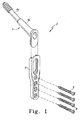
- the implant components comprise an implant assembly 2 that includes a captured screw assembly 4, a side plate 6, and a plurality of bone screws 8 as shown in FIG. 1 .
- the captured screw assembly 4 includes a lag screw 4a and a barrel 4b.
- the implant assembly 2 is described in detail in US-4438762 .
- FIGS. 2 to 5 An instrument that facilitates implantation of the captured screw assembly 4 is a guide assembly 10 shown in FIGS. 2 to 5 .
- the guide assembly 10 is used to direct a guide pin 12 into a shaft, neck, and head of a femur such femur F shown in FIGS. 6 and 7 through an incision I in a patient P. Note that FIGS. 6 and 7 show a fracture 13 in the femur F.
- the guide assembly 10 includes a shaft 14 and a guide tube 16.
- the shaft 14 includes a set of external threads 15 as shown in FIG. 3 .
- the guide tube 16 defines a lumen 18 through which the guide pin 12 may be advanced.
- the guide tube 16 is fixedly attached to the shaft 14 so that the guide tube 16 cannot move in relation to the shaft 14.
- the guide assembly 10 further includes a handle 20 that is attached to the shaft 14.
- a pin 22 is positioned within a bore 24 defined in the handle 20, as well as another bore 26 defined in the shaft 14.
- the guide assembly 10 further includes a foot 28 that is pivotably connected to the shaft 14. In particular, the foot 28 is configured to pivot in relation to the shaft 14 about a pin 30 from its position shown in FIG. 4 to its position shown in FIG. 5 .
- the guide assembly 10 further includes a locking sleeve 32 that defines a passageway 34 through which the shaft 14 extends.
- the guide assembly 10 further includes a locking nut 36 that includes a passageway 38.
- the locking nut 36 includes a set of internal threads (not shown) located within the passageway 38 which can mesh with the set of external threads 15 of the shaft 14.
- the locking sleeve 32 includes a tang 40 that may be urged into any of two grooves defined on the foot 28 so as to lock the foot 28 in relation to the shaft 14 in any of two fixed positions.
- a third groove may be provided on the foot 28 to allow the foot 28 to be locked in a third position, namely, the position shown in FIG. 5 as will be discussed below.
- the foot 28 has a first groove 41 defined therein.
- the locking nut 36 urges the locking sleeve 32 toward the foot 28 until the tang 40 is advanced into the groove 41 thereby locking the foot 28 in fixed relation to the shaft 14 at the angle shown in FIG. 4 .
- the foot 28 is locked at this position in relation to the shaft 14 during insertion of the guide pin 12 through the guide tube 16 and into the shaft, neck, and head of the femur F during a hip fracture reduction procedure.
- the position of the foot 28 relative to the shaft 14 may be adjusted by rotating the locking nut 36 in a direction opposite to the first direction discussed above thereby allowing the locking sleeve 32 to be advanced away from the foot 28. Once the tang 40 is advanced out of the groove 41, the foot 28 may be moved to its position shown in FIG. 5 . As will be discussed below, the foot 28 assumes this position in relation to the shaft 14 during insertion (and removal) of the guide assembly 10 through the incision I of the patient P during the hip fracture reduction procedure.
- the groove 41 is located on a first side 44 of the foot 28.
- the foot 28 includes another groove (not shown) on a second side 46 of the foot 28 at a location slightly offset from the location of the groove 41 on the first side 44. It should be appreciated that use of the groove 41 allows the foot 28 to be locked in fixed relation to the shaft 14 at the position shown in FIG. 4 , while the use of the groove (not shown) defined on the second side 46 of the foot 28 allows the foot 28 to be locked in fixed relation to the shaft 14 at a position that is slightly different from the position shown in FIG. 4 .
- the groove (not shown) defined on the second side 46 of the foot 28 allows the foot 28 to be locked in fixed relation to the shaft 14 at an angle that is different by about 10 degrees in relation to the angle shown in FIG. 4 .
- the groove 41 is located on the foot 28 to cause the foot to be locked in fixed relation to the shaft so that an angle of 135° is defined by the axis of the guide tube 16 and the axis of the foot 28, while the groove (not shown) on the second side 46 of the foot 28 is located on the foot to cause the foot to be locked in fixed relation to the shaft so that an angle of 145° is defined by the axis of the guide tube 16 and the axis of the foot 28.
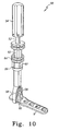
- FIGS. 8 to 11 there is shown a plate holder assembly 50 that is used to facilitate implantation of the side plate 6 and the bone screws 8 of the implant assembly 2 into the patient P.
- the plate holder assembly 50 is used to retain the side plate 6 during insertion of the side plate 6 through the incision I in the patient P.
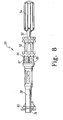
- the plate holder assembly 50 includes a shaft 52, a handle assembly 54, a holder (or inner collet) 56, an actuator (or outer collet) 58, a foot 60, a driver (or locking nut) 62, and a locking ring 64.
- the handle assembly 54 includes a handle member 66 defining a recess 68, and an insert 70 located within the recess 68. Also located within the recess 68 is a plurality of ball plungers 72 that cooperate with the insert 70 to releasibly secure the handle member 66 to the shaft 52.
- FIGS. 14 to 16 show the holder 56 in more detail.
- the holder 56 defines a central passageway 74 which is configured to receive the shaft 52.
- the holder 56 includes an arm 76 and an arm 78 that are spaced apart from each other.
- the arm 76 includes an inwardly extending projection 80, while the arm 78 includes an inwardly extending projection 82.
- the holder 56 has a set of external threads 81 as shown in FIGS. 14 to 16 .
- the holder 56 further has a set of internal threads 83 located within the central passageway 74.
- the set of internal threads 83 is configured to mesh with a set of external threads 85 of the shaft 52.
- the set of external threads of shaft 52 are shown in FIGS. 17 and 18 .
- FIGS. 19 to 21 show the actuator 58 in more detail.
- the actuator 58 defines a central passageway 84 which is configured to receive the holder 56.
- the actuator 58 includes an arm 86 and an arm 88 that are spaced apart from each other.
- a polygonal-shaped exterior surface 87 At a proximal end portion of the actuator 58, there is defined a polygonal-shaped exterior surface 87.
- the polygonal-shaped surface 87 is hexagonal-shaped.
- the surface 87 may possess other polygonal shapes such as rectangular and octagonal.
- the actuator 58 further includes a ledge that defines a clamping surface 89.
- the foot 60 includes a passageway 90 that is configured to receive a distal end of the shaft 52. Note that the distal end portion of the shaft 52 has defined therein a fastener bore 92 as shown in FIG. 18 .
- a fastener 94 (shown in FIG. 26 ) is threadingly engaged to within the fastener bore 92 to secure the foot 60 to the shaft 52.
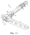
- FIG. 11 shows the fastener 94 securing the foot 60 to the shaft 52.
- the shaft 52, the foot 60, and the fastener 94 are configured such that when the foot 60 is secured to the shaft 52 by the fastener 94, the shaft 52 is free to rotate 360° in relation to the foot 60.
- the foot 60 further includes an impactor recess 96 configured to receive the distal end of an impactor 112 (see FIG. 30 ). It should be appreciated that the foot 60 and shaft 52 of the plate holder assembly collectively operate as a press to urge the side plate 6 into contact with the projections 80, 82 of the holder arms 76, 78.
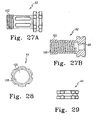
- FIGS. 27A and 27B show the driver 62 in more detail.
- the driver 62 includes a central passageway 98.
- a set of internal threads 100 are located within the central passageway 98.
- the driver 62 also includes a set of external threads 102 as shown in FIGS. 27A and 27B .
- the set of internal threads 100 is configured to mesh with the set of external threads 81 of the holder 56.
- FIGS. 28 and 29 show the show the locking ring 64 in more detail.
- the locking ring 64 includes a central passageway 106.
- a set of internal threads 108 are located within the central passageway 106.
- the set of internal threads 108 is configured to mesh with the set of external threads 102 of the driver 52.
- the plate holder assembly 50 When assembled, the plate holder assembly 50 is configured to releasibly retain the side plate 6 as shown in FIGS. 10 and 11 .
- the following manipulations must occur.
- the foot 60 must be move away from the projections 80, 82, and the holder arms 76, 78 must be moved outwardly relative to each other.
- the handle assembly 54 and thus the shaft 52 are rotated in a first direction in relation to the holder 56. This rotation causes axial displacement of the shaft 52 in relation to the holder 56 thereby moving the foot 60 axially away from the projections 80, 82.
- the driver 62 In order to move the holder arms 76, 78 outwardly, the driver 62 is rotated in a first direction thereby causing the driver to be advanced toward the handle assembly 54 and away from the actuator 58. A space is thereby created which allows the actuator 58 to be advanced toward the handle assembly 54 and away from the foot 60. Note that prior to advancement of the actuator 58 (at the relative positioning of the actuator 58 and holder 56 shown in FIG. 8 ), the arms 86, 88 of the actuator are respectively urged into contact with the arms 76, 78 of the holder 56 thereby biassing the holder arms 76, 78 a distance inwardly.
- the actuator arms 86, 88 are advanced axially and out of contact with the holder arms 76, 78 thereby allowing the holder arms 76, 78 to spring outwardly.
- the arm 76 defines a bone plate contact portion 76C on a surface thereof, while the arm 78 defines a bone plate contact portion 78C as shown in FIGS. 14 and 16 .
- the actuator 58 and holder 56 are positioned as shown in FIG. 8 , the bone plate contact portion 76C and the bone plate contact portion 78C are separated by a first distance.
- the holder arms 76, 78 spring outwardly so that the bone plate contact portion 76C and the bone plate contact portion 78C are now separated by a second distance which is greater than the first distance. While the bone plate contact portions 76C, 78C are separated by the second distance, the side plate 6 may be inserted between the foot 60 and the projections 80, 82 of the holder arms 76, 78 in the direction shown by arrow 110 in FIG. 11 .
- the side plate 6 is advanced in the direction indicated by arrow 110 in FIG. 11 until the foot 60 is aligned with the largest opening of the side plate 6. Thereafter, the handle assembly 54 and thus the shaft 52 is rotated in a second direction in relation to the holder 56, opposite to the first direction discussed above. This rotation causes the axial displacement of the shaft 52 in relation to the holder 56 thereby moving the foot 60 axially toward the projections 80, 82. This rotation is continued until the side plate 6 becomes clamped between the foot 60 and the projections 80 and 82. Then, the driver 62 is rotated in a second direction, opposite the first direction discussed above, so as to cause the driver to be advanced toward the foot 60.
- Advancing the driver toward the foot 60 causes the actuator arms 86, 88 to be advanced toward the holder arms 76, 78.
- Continued advancement of the actuator arms 86, 88 results in the actuator arms 86, 88 slidingly contacting the holder arms 76, 78 thereby urging them inwardly.
- Inward movement of the holder arms 76, 78 causes the bone plate contact portions 76C, 78C to clamp the side plate 6 between them as shown in FIG. 11 .
- the side plate 6 With the side plate 6 securely retained between the bone plate contact portions 76C, 78C, as well as between the foot 60 and the projections 80, 82 of the holder arms 76, 78 as described above, the side plate 6 may be inserted through the incision I in the patient P with the assistance of the plate holder assembly 50.
- the side plate 6 is manipulated with the plate holder assembly 50 to mate the side plate 6 to the barrel 4b of the captured screw assembly 4 inside the wound.
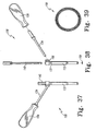
- the distal end of the impactor 112 is inserted into the impactor recess 96 of the foot 60 as shown in FIG. 30 .
- the proximal end of the impactor is tapped three or four times with a mallet to transfer force to the side plate 6 to ensure that the side plate 6 and the barrel 4b are fully mated.
- the impactor 112 is shown in more detail in FIG. 30 .
- the impactor 112 includes a handle 114, a shaft 116, and a strike cap 118.
- the shaft 116 is connected to a distal end of the handle 114, while the strike cap 118 is connected to a proximal end of the handle 114.
- the distal end of the impactor 112 is removed from the impactor recess 96 and a targeting component 120 is attached to the actuator 56 as shown in FIG. 32 .
- the targeting component 120 component is shown in more detail in FIGS. 33 to 35 .
- the targeting component 120 defines a plurality of holes 121.
- the targeting component 120 includes a mating surface 122 that is configured to be at least partially complementary to the polygonal-shaped surface 87 of the actuator 58. In order to attach the targeting component 120 to the actuator 56, the targeting component is advanced toward the actuator until the mating surface 122 mates with the polygonal-shaped surface 87.
- the locking ring 64 is rotated in relation to the driver 62 thereby advancing the locking ring 64 toward the targeting component 120. Further advancement of the locking ring 64 causes the locking ring to contact and clamp the targeting component 120 between the locking ring 64 and the clamping surface 89 of the actuator 58 as shown in FIG. 32 .
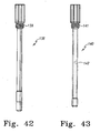
- a drill guide assembly 130 is used with the targeting component 120 for this purpose, and is shown in detail in FIGS. 36 to 43 .
- the drill guide assembly 130 includes outer sheath 132 that is configured to be received in any of the plurality of holes 121 of the targeting component 120.
- FIG. 36 shows the outer sheath 132 extending through of the holes 121 of the targeting component 120.
- the handle assembly 54 is separated from the shaft 52 to allow ample space for manipulating the drill guide assembly 130 in relation to the targeting component 120.
- the outer sheath 132 defines a groove 137 on an outer surface thereof.
- a spring 150 is configured to extend circumferentially around the outer sheath 132 and be received in the groove 137.
- the spring 150 is shown in detail in FIG. 39 .
- the spring 150 assists in holding the outer sheath 132 in fixed relation to the targeting component 120.
- the drill guide assembly 130 further includes a handle shaft 134 attached to the outer sheath 132, and a handle 136 attached to the handle shaft 134.
- the outer sheath 132 defines a central passageway 133 extending therethrough.
- the outer sheath 132 includes a set of internal threads 135 located within the central passageway 133.
- the drill guide assembly 130 further includes a trocar 138 that is configured to extend through the central passageway 133.
- the trocar 138 is solid in cross section so that no passageway is defined therethrough.
- the trocar 138 has a set of external threads 139 configured to meshingly engage with the set of internal threads 135 so as to removably secure the trocar 138 to the outer sheath 132.
- the drill guide assembly 130 also includes an inner sheath 140 that is configured to extend through the central passageway 133.
- the inner sheath 140 defines a central passageway 142 extending therethrough.
- the inner sheath 140 also has a set of external threads 141 configured to meshingly engage with the set of internal threads 135 so as to removably secure the inner sheath 140 to the outer sheath 132.
- the inner sheath 140 is configured to allow for the passage of a drill (for example a 3.8 mm drill), while the outer sheath 132 is configured to allow for the passage of a hex driver (for example a 4.5 mm hex driver shank) therethrough.
- a guide pin 12 (for example a 3.2 mm guide pin) is exteriorly placed above the femoral neck to assess lateral positioning and neck angle.
- the tip of the guide pin is placed radiographically at the tip of the lesser trochanter of the femur F in the A/P plane with the pin extending laterally.
- a skin marker is used to place a line along this guide pin laterally.
- the tip of the guide pin is radiographically placed at the apex of the femoral head, extending laterally and centrally down the femoral neck.
- a skin marker is again used to place a line along the guide pin extending to the posterior lateral aspect of the thigh.
- the guide pin is placed longitudinally parallel to the lateral view of the femoral shaft and a line is created that intersects the point where the first two lines intersect.
- a line is created that intersects the point where the first two lines intersect.
- an 3 to 5 cm incision I length 3 to 5 cm, is made which extends distally.
- the dissection is carried sharply down through the skin and subcutaneous tissue to the fascia lata.
- the fascia lata is then split longitudinally, exposing the vastus lateralis to expose the lateral aspect of the femoral shaft.
- the skin may be retracted using retractors if desired.
- the guide assembly 10 is then aligned such that the side 44 of the foot 60 or the side 46 of the foot 60 is facing upward and is visible, depending on the location of the fracture 13. This will ensure that the guide tube 16 of the guide assembly 10 is aligned to target the femoral head.
- the foot 60 of the guide assembly 10 is moved to its position shown in FIG. 5 .
- the foot 60 may further include a groove 154 that is aligned with the central axis of the guide assembly 10 which is similar in configuration to the groove 41 so that the foot 60 may be locked in fixed relation to the locking sleeve 32 in a manner similar to that discussed above with respect to locking the foot 60 at the position shown in FIG. 4 .
- the foot 60 is inserted through the incision I until the tip of the foot 60 makes contact with the lateral aspect of the femur F.
- the locking nut 36 of the guide assembly 10 is then rotated until the foot 60 is free to pivot in relation to the locking sleeve 32.
- the foot 60 is slid distally along the lateral cortex of the femur F until the foot 60 is in a desired position.
- the locking nut 36 is rotated in an opposite direction to that discussed above thereby causing the locking nut to urge the locking sleeve 32 distally to engage the tang 40 within the groove 41 of the foot 60. So positioned, the foot 60 is fixed in relation to the locking sleeve 32 at the position shown in FIG. 4 .
- the guide tube 16 should now be positioned relative to the femur F so that the guide tube will direct the guide pin 12 to lie at the highest angle necessary to position the pin next to the medial cortex and in the center of the femoral head in the anterior/posterior (A/P) plane.
- the guide pin 12 is then advanced through the guide tube 16 and the center of the femoral head in both the A/P and lateral planes to within 5 to 7 mm of the subchondral bone as is done.
- the locking nut 36 of the guide assembly 10 is rotated so as to free pivoting of the foot 60. Thereafter, the foot 60 of the guide assembly 10 is advanced out of the wound through the incision I.
- a reamer (not shown) is placed over the guide pin 12 and advanced through the incision I and into the proximal femur under image control as is done in a conventional procedure.
- a calibrated tap (not shown) is placed over the guide pin 12 and the neck and head of the femur F is tapped to within 5 to 7 mm of subchondral bone under image control.
- FIG. 7 shows the captured screw assembly 2 in the process of being implanted in the femur F over the guide pin 12.
- FIG. 44 shows the captured screw assembly 2 secured to the femur in accordance with the minimal incision technique. (Note that FIG. 44 shows the femur F and the captured screw assembly 2 removed from the body for clarity of viewing.)
- the side plate 6 may be assembled to the barrel 4b. This is accomplished with the assistance of the plate holder assembly 50. A selected side plate 6 is pre-assembled to the plate holder assembly 50 through manipulation of the handle assembly 54 and the driver 62 as described above. Note that the handle assembly 54 and the driver 62 must both be rotated fully counter-clockwise to allow the side plate 6 to be advanced between the arms 76, 78 of the holder 56.
- the driver 62 is advanced clockwise to close the arms 76, 78 on to the sides of the side plate 6, and then the handle assembly 54 is rotated clockwise until the side plate 6 is securely fastened in the distal part of the plate holder assembly 50.
- the driver 62 may have a positive stop built into it that is reached to ensure that the plate is fully locked.
- the handle assembly 54 is rotated until it can no longer advance.
- verification is made that the distal screw holes of the side plate 6 are on the same side of the foot 60 as the impactor recess 96 defined in the foot 60. Proper orientation of the side plate 6 with respect to the foot 60 is shown in FIG. 10 .
- the plate holder assembly 50 is now manipulated to insert the side plate 6 through the incision I, and thereafter mate the side plate 6 with the barrel 4b of the captured screw assembly 2.
- the impactor 112 is manipulated until its distal end is received within the impactor recess 96 of the foot 60. Thereafter, the proximal end of the impactor is tapped firmly several times (e.g. three or four) to transmit force to the side plate 6 thereby ensuring the side plate 6 and the barrel 4b are fully mated.
- the targeting component 120 is attached to the actuator 58 in the manner discussed above.
- the locking ring 64 is unthreaded from the set of external threads 102 on the locking ring 64 and then slid proximally.
- the mating surface 122 of the targeting component 120 is mated with the polygonal-shaped surface 87 of the actuator 58.
- the set of internal threads 108 of the locking ring 64 are meshingly engaged with the set of external threads of the driver 62 and tightened down. This causes the locking ring 64 to contact the targeting component 120 thereby securing the targeting component between the locking ring 64 and the clamping surface 89 of the actuator 58 (see FIG. 32 ).
- the drill guide assembly 130 (with neither the trocar 138 nor the inner sheath 140 located within the central passageway 133 of the outer sheath 132) is then inserted into the most proximal hole 121 of the targeting component 120.
- the handle assembly 54 may be separated from the shaft 52 prior to this step.
- the drill guide assembly 130 is advanced until the distal end of the outer sheath 132 touches skin of the patient P. A mark is then made for a stab incision, and the skin is thereafter incised.
- the trocar 138 is then advanced into the central passageway 133 of the outer sheath 132 and thereafter its set of external threads 139 are mated with the set of internal threads 135 of the outer sheath 132.
- the outer sheath is advanced until its distal tip contacts the side plate 6 in the most proximal hole 131.
- a shoulder 158 (see FIG. 37 ) defined on a proximal portion of the outer sheath 132 is in contact with a top surface of the targeting component 120 thereby indicating that it is fully seated.
- the trocar 138 is removed from the central passageway 133 of the outer sheath 132.
- the inner sheath 140 is now advanced into the central passageway 133 of the outer sheath 132 and thereafter its set of external threads 141 are mated with the set of internal threads 135 of the outer sheath 132.
- a drill (not shown) is advanced into the central passage 142 of the inner sheath 140 and is manipulated under fluoroscopy to drill both cortices of the femur F.
- the drill may be a 3.8 mm calibrated drill.
- the measurement on the drill is then noted when the tip of the drill protrudes from the medial cortex of the femur.
- a depth gauge device may also be used for this purpose.
- a power adaptor or a quick couple T-handle is then assembled to a 4.5 mm solid hex driver shank (as in a conventional technique).
- the inner sheath 140 is removed from the outer sheath 132 and the 4.5 mm self-tapping screw 8 is driven through the outer sheath 132 and into the hole in the side plate 6 thereby securing the side plate 6 to the shaft of the femur F.
- the same procedure is repeated for placement of all of the screws 8 of the side plate 6.
- the targeting component 120 is detached from the actuator 58. Additional impaction with the impactor 112 (in a manner similar to the impaction described above) is performed, if desired.
- the impactor 112 may again be used to impact the side plate 6 into the barrel 4b with three to four firm taps on the strike cap 118 with a mallet.
- the plate holder assembly 50 is separated from the side plate 6 and removed from the wound.
- the side plate 6 is released by the plate holder assembly 50 by first turning the handle assembly 54 counter-clockwise until it is fully retracted. Then, the driver 62 is released, also by turning it counter-clockwise until fully retracted. These acts will cause the plate holder assembly 50 to release from the side plate 6. After such release, the plate holder assembly 50 is pulled out of the wound through the incision I in a direction perpendicular to the side plate 6. Slight anterior/posterior (A/P) movement of the plate holder assembly 50 may be necessary to fully disengage the plate holder assembly 50 from the side plate 6. Thereafter, the wound is closed in a conventional manner.
- A/P anterior/posterior
Landscapes
- Health & Medical Sciences (AREA)
- Orthopedic Medicine & Surgery (AREA)
- Surgery (AREA)
- Life Sciences & Earth Sciences (AREA)
- Heart & Thoracic Surgery (AREA)
- Nuclear Medicine, Radiotherapy & Molecular Imaging (AREA)
- Engineering & Computer Science (AREA)
- Biomedical Technology (AREA)
- Medical Informatics (AREA)
- Molecular Biology (AREA)
- Animal Behavior & Ethology (AREA)
- General Health & Medical Sciences (AREA)
- Public Health (AREA)
- Veterinary Medicine (AREA)
- Neurology (AREA)
- Surgical Instruments (AREA)
- Prostheses (AREA)
Applications Claiming Priority (1)
| Application Number | Priority Date | Filing Date | Title |
|---|---|---|---|
| US11/789,332 US8197484B2 (en) | 2007-04-24 | 2007-04-24 | Assembly for minimally invasive reduction of hip fracture |
Publications (1)
| Publication Number | Publication Date |
|---|---|
| EP1985249A1 true EP1985249A1 (de) | 2008-10-29 |
Family
ID=39596324
Family Applications (1)
| Application Number | Title | Priority Date | Filing Date |
|---|---|---|---|
| EP08251504A Withdrawn EP1985249A1 (de) | 2007-04-24 | 2008-04-23 | Anordnung zur minimal-invasiven Reduzierung von Hüftbrüchen |
Country Status (3)
| Country | Link |
|---|---|
| US (1) | US8197484B2 (de) |
| EP (1) | EP1985249A1 (de) |
| JP (1) | JP2009022734A (de) |
Cited By (3)
| Publication number | Priority date | Publication date | Assignee | Title |
|---|---|---|---|---|
| CN103876818A (zh) * | 2012-12-19 | 2014-06-25 | 财团法人工业技术研究院 | 骨板结构及手术器械 |
| TWI563962B (zh) * | 2012-12-19 | 2017-01-01 | 財團法人工業技術研究院 | 骨板結構及手術器械 |
| EP3785650A1 (de) * | 2019-08-30 | 2021-03-03 | K2M, Inc. | Kompletter plattenhalter und federbelastete ahle |
Families Citing this family (15)
| Publication number | Priority date | Publication date | Assignee | Title |
|---|---|---|---|---|
| US7837689B2 (en) * | 2007-09-27 | 2010-11-23 | Depuy Products, Inc. | Plate holder assembly having bone plate seating confirmation arrangement |
| AU2010319537A1 (en) * | 2009-11-10 | 2012-05-31 | Smith & Nephew, Inc. | Controlling bone compression |
| US8858636B2 (en) | 2010-04-09 | 2014-10-14 | DePuy Synthes Products, LLC | Intervertebral implant |
| US9301853B2 (en) * | 2010-04-09 | 2016-04-05 | DePuy Synthes Products, Inc. | Holder for implantation and extraction of prosthesis |
| US8419745B2 (en) | 2010-04-23 | 2013-04-16 | Biomet C.V. | Bone plate bender system |
| WO2012026833A1 (en) * | 2010-08-26 | 2012-03-01 | Lanzatech New Zealand Limited | Process for producing ethanol and ethylene via fermentation |
| US11123117B1 (en) | 2011-11-01 | 2021-09-21 | Nuvasive, Inc. | Surgical fixation system and related methods |
| US8900245B2 (en) * | 2012-06-07 | 2014-12-02 | Howmedica Osteonics Corp. | Glenosphere inserter and impactor |
| US9216043B2 (en) * | 2013-03-14 | 2015-12-22 | Medos International Sarl | Devices and methods for monoaxial screw conversion |
| US9681904B2 (en) * | 2014-01-02 | 2017-06-20 | DePuy Synthes Products, Inc. | Method and device for attaching a bone plate |
| DE102015117884B4 (de) * | 2015-10-21 | 2019-05-23 | Ryszard van Rhee | Fixiervorrichtung zur unterstützten Handhabung und Befestigung operativ therapeutischer Platten zur weniger invasiven operativen Versorgung des Hallux valgus |
| GB201600426D0 (en) | 2016-01-11 | 2016-02-24 | At Ortho Ltd | Surgical implants,methods and apparatus for use in surgery |
| US11129627B2 (en) | 2019-10-30 | 2021-09-28 | Globus Medical, Inc. | Method and apparatus for inserting a bone plate |
| AU2021376224A1 (en) * | 2020-11-06 | 2023-06-22 | Stryker Corporation | Robotic hand-held surgical instrument systems and methods |
| US12035928B2 (en) * | 2021-11-12 | 2024-07-16 | NextWave Medical, LLC | Devices and methods for correction of hip deformities |
Citations (8)
| Publication number | Priority date | Publication date | Assignee | Title |
|---|---|---|---|---|
| US2526959A (en) | 1947-07-01 | 1950-10-24 | Frank A Lorenzo | Fracture reduction apparatus |
| US3554193A (en) | 1968-07-05 | 1971-01-12 | Ilias Konstantinou | Femur-setting surgical device |
| US4009712A (en) * | 1975-08-07 | 1977-03-01 | The Sampson Corporation | Fluted hip nail implant system for orthopaedic surgery |
| US4438762A (en) | 1981-12-30 | 1984-03-27 | Richard F. Kyle | Orthopedic hip fixation device |
| WO2003015650A1 (en) * | 2001-08-21 | 2003-02-27 | Depuy Products, Inc. | Method and apparatus for percutaneously securing a bone screw and a bone plate to a bone of a patient |
| US20040260289A1 (en) * | 2001-08-23 | 2004-12-23 | Martin Padget | Deployment tool for distal bone anchors with secondary compression |
| US20050038444A1 (en) * | 2003-08-13 | 2005-02-17 | Binder Lawrence J. | Quick-release drill-guide assembly for bone-plate |
| WO2007092441A2 (en) * | 2006-02-08 | 2007-08-16 | Synthes (U.S.A.) | Transbuccal plate holding cannula |
Family Cites Families (13)
| Publication number | Priority date | Publication date | Assignee | Title |
|---|---|---|---|---|
| US3945377A (en) * | 1975-01-24 | 1976-03-23 | Kronner Richard F | Hip pinning tool |
| US4465065A (en) | 1983-01-07 | 1984-08-14 | Yechiel Gotfried | Surgical device for connection of fractured bones |
| US5116338A (en) * | 1988-02-03 | 1992-05-26 | Pfizer Hospital Products Group, Inc. | Apparatus for knee prosthesis |
| FR2823096B1 (fr) * | 2001-04-06 | 2004-03-19 | Materiel Orthopedique En Abreg | Plaque pour dispositif d'osteosynthese des vertebres l5 et s1, dispositif d'osteosynthese incluant une telle plaque, et instrument pour la pose d'une telle plaque |
| US20050049594A1 (en) * | 2001-04-20 | 2005-03-03 | Wack Michael A. | Dual locking plate and associated method |
| US6440142B1 (en) * | 2001-04-27 | 2002-08-27 | Third Millennium Engineering, Llc | Femoral ring loader |
| US6440133B1 (en) * | 2001-07-03 | 2002-08-27 | Sdgi Holdings, Inc. | Rod reducer instruments and methods |
| US7887539B2 (en) * | 2003-01-24 | 2011-02-15 | Depuy Spine, Inc. | Spinal rod approximators |
| US7842044B2 (en) * | 2003-12-17 | 2010-11-30 | Depuy Spine, Inc. | Instruments and methods for bone anchor engagement and spinal rod reduction |
| JP4213609B2 (ja) * | 2004-03-09 | 2009-01-21 | 昭和医科工業株式会社 | ロッド固定用補助器具 |
| US7651502B2 (en) * | 2004-09-24 | 2010-01-26 | Jackson Roger P | Spinal fixation tool set and method for rod reduction and fastener insertion |
| US7481813B1 (en) * | 2004-11-19 | 2009-01-27 | Alphatec Spine, Inc. | Securing device and corresponding methods thereof for bone fixation systems |
| US7608081B2 (en) * | 2005-05-23 | 2009-10-27 | Custom Spine, Inc. | Rod reducer |
-
2007
- 2007-04-24 US US11/789,332 patent/US8197484B2/en active Active
-
2008
- 2008-04-23 JP JP2008112415A patent/JP2009022734A/ja active Pending
- 2008-04-23 EP EP08251504A patent/EP1985249A1/de not_active Withdrawn
Patent Citations (8)
| Publication number | Priority date | Publication date | Assignee | Title |
|---|---|---|---|---|
| US2526959A (en) | 1947-07-01 | 1950-10-24 | Frank A Lorenzo | Fracture reduction apparatus |
| US3554193A (en) | 1968-07-05 | 1971-01-12 | Ilias Konstantinou | Femur-setting surgical device |
| US4009712A (en) * | 1975-08-07 | 1977-03-01 | The Sampson Corporation | Fluted hip nail implant system for orthopaedic surgery |
| US4438762A (en) | 1981-12-30 | 1984-03-27 | Richard F. Kyle | Orthopedic hip fixation device |
| WO2003015650A1 (en) * | 2001-08-21 | 2003-02-27 | Depuy Products, Inc. | Method and apparatus for percutaneously securing a bone screw and a bone plate to a bone of a patient |
| US20040260289A1 (en) * | 2001-08-23 | 2004-12-23 | Martin Padget | Deployment tool for distal bone anchors with secondary compression |
| US20050038444A1 (en) * | 2003-08-13 | 2005-02-17 | Binder Lawrence J. | Quick-release drill-guide assembly for bone-plate |
| WO2007092441A2 (en) * | 2006-02-08 | 2007-08-16 | Synthes (U.S.A.) | Transbuccal plate holding cannula |
Cited By (7)
| Publication number | Priority date | Publication date | Assignee | Title |
|---|---|---|---|---|
| CN103876818A (zh) * | 2012-12-19 | 2014-06-25 | 财团法人工业技术研究院 | 骨板结构及手术器械 |
| US9241747B2 (en) | 2012-12-19 | 2016-01-26 | Industrial Technology Research Institute | Bone plate structure, surgery device and method for bone plate implant |
| CN103876818B (zh) * | 2012-12-19 | 2016-08-17 | 财团法人工业技术研究院 | 骨板结构及手术器械 |
| TWI563962B (zh) * | 2012-12-19 | 2017-01-01 | 財團法人工業技術研究院 | 骨板結構及手術器械 |
| EP3785650A1 (de) * | 2019-08-30 | 2021-03-03 | K2M, Inc. | Kompletter plattenhalter und federbelastete ahle |
| US11793558B2 (en) | 2019-08-30 | 2023-10-24 | K2M, Inc. | All in one plate holder and spring loaded awl |
| US12201335B2 (en) | 2019-08-30 | 2025-01-21 | K2M, Inc. | All in one plate holder and spring loaded awl |
Also Published As
| Publication number | Publication date |
|---|---|
| JP2009022734A (ja) | 2009-02-05 |
| US8197484B2 (en) | 2012-06-12 |
| US20080275447A1 (en) | 2008-11-06 |
Similar Documents
| Publication | Publication Date | Title |
|---|---|---|
| US8197484B2 (en) | Assembly for minimally invasive reduction of hip fracture | |
| US12295634B2 (en) | Bone fixation system, assembly, implants, devices, alignment guides, and methods of use | |
| JP4823610B2 (ja) | 骨プレーティングインプラント器具および方法 | |
| EP1878394B1 (de) | Orthopädische Befestigungsplatte mit einschraubbarer Bohrerführung | |
| JP4291691B2 (ja) | 整形外科用インプラント挿入器具 | |
| US7396360B2 (en) | Minimally invasive method and apparatus for fusing adjacent vertebrae | |
| US5403322A (en) | Drill guide and method for avoiding intramedullary nails in the placement of bone pins | |
| JP4294479B2 (ja) | 骨ねじ及び骨プレートを患者の骨に経皮的に固定するための方法及び装置 | |
| JP2003199757A (ja) | 脊椎の安定化のための外科案内システム | |
| CN102665582A (zh) | 髓间系统和方法 | |
| US20220296285A1 (en) | Intramedullary implant for transverse osteotomy | |
| US12133668B2 (en) | Endosteal guide pin, positioning trocar and trocar for removing said pin | |
| US20260020880A1 (en) | Surgical systems and methods including aligning guides for performing a percutaneous bunion correction | |
| US20130012948A1 (en) | Alignment jig for a bone fixation device | |
| US20230338074A1 (en) | Guided systems and methods for implanting fasteners into tissue | |
| EP1435850B1 (de) | Instrument zum einsetzen eines orthopädischen implantates | |
| WO2025155566A1 (en) | Mis beveled driver for implanting ibs bone compression screws | |
| AU2002340219A1 (en) | Orthopedic implant insertion instruments |
Legal Events
| Date | Code | Title | Description |
|---|---|---|---|
| PUAI | Public reference made under article 153(3) epc to a published international application that has entered the european phase |
Free format text: ORIGINAL CODE: 0009012 |
|
| AK | Designated contracting states |
Kind code of ref document: A1 Designated state(s): AT BE BG CH CY CZ DE DK EE ES FI FR GB GR HR HU IE IS IT LI LT LU LV MC MT NL NO PL PT RO SE SI SK TR |
|
| AX | Request for extension of the european patent |
Extension state: AL BA MK RS |
|
| 17P | Request for examination filed |
Effective date: 20081112 |
|
| 17Q | First examination report despatched |
Effective date: 20081215 |
|
| STAA | Information on the status of an ep patent application or granted ep patent |
Free format text: STATUS: THE APPLICATION HAS BEEN WITHDRAWN |
|
| AKX | Designation fees paid |
Designated state(s): AT BE BG CH CY CZ DE DK EE ES FI FR GB GR HR HU IE IS IT LI LT LU LV MC MT NL NO PL PT RO SE SI SK TR |
|
| 18W | Application withdrawn |
Effective date: 20090423 |