EP1985169B1 - Transmission device of walking type self-traveling lawn mower - Google Patents
Transmission device of walking type self-traveling lawn mower Download PDFInfo
- Publication number
- EP1985169B1 EP1985169B1 EP07713843A EP07713843A EP1985169B1 EP 1985169 B1 EP1985169 B1 EP 1985169B1 EP 07713843 A EP07713843 A EP 07713843A EP 07713843 A EP07713843 A EP 07713843A EP 1985169 B1 EP1985169 B1 EP 1985169B1
- Authority
- EP
- European Patent Office
- Prior art keywords
- output shaft
- drive
- chain
- rotating
- transmission
- Prior art date
- Legal status (The legal status is an assumption and is not a legal conclusion. Google has not performed a legal analysis and makes no representation as to the accuracy of the status listed.)
- Active
Links
- 230000005540 biological transmission Effects 0.000 title claims abstract description 142
- 230000007246 mechanism Effects 0.000 claims abstract description 109
- 230000002093 peripheral effect Effects 0.000 claims description 31
- 239000000314 lubricant Substances 0.000 claims description 8
- 230000009467 reduction Effects 0.000 description 9
- 238000004519 manufacturing process Methods 0.000 description 6
- 230000008901 benefit Effects 0.000 description 5
- 230000008878 coupling Effects 0.000 description 5
- 238000010168 coupling process Methods 0.000 description 5
- 238000005859 coupling reaction Methods 0.000 description 5
- 239000004519 grease Substances 0.000 description 3
- 238000004804 winding Methods 0.000 description 3
- 230000008859 change Effects 0.000 description 2
- 238000004891 communication Methods 0.000 description 2
- 230000007547 defect Effects 0.000 description 2
- 230000000694 effects Effects 0.000 description 2
- 238000012423 maintenance Methods 0.000 description 2
- 238000000034 method Methods 0.000 description 2
- 238000004140 cleaning Methods 0.000 description 1
- 230000000593 degrading effect Effects 0.000 description 1
- 230000001419 dependent effect Effects 0.000 description 1
- 230000002452 interceptive effect Effects 0.000 description 1
- JEIPFZHSYJVQDO-UHFFFAOYSA-N iron(III) oxide Inorganic materials O=[Fe]O[Fe]=O JEIPFZHSYJVQDO-UHFFFAOYSA-N 0.000 description 1
- 239000000463 material Substances 0.000 description 1
- 238000003825 pressing Methods 0.000 description 1
- 230000002265 prevention Effects 0.000 description 1
- 238000007789 sealing Methods 0.000 description 1
- 230000009291 secondary effect Effects 0.000 description 1
Images


Classifications
-
- A—HUMAN NECESSITIES
- A01—AGRICULTURE; FORESTRY; ANIMAL HUSBANDRY; HUNTING; TRAPPING; FISHING
- A01D—HARVESTING; MOWING
- A01D34/00—Mowers; Mowing apparatus of harvesters
- A01D34/01—Mowers; Mowing apparatus of harvesters characterised by features relating to the type of cutting apparatus
- A01D34/412—Mowers; Mowing apparatus of harvesters characterised by features relating to the type of cutting apparatus having rotating cutters
- A01D34/63—Mowers; Mowing apparatus of harvesters characterised by features relating to the type of cutting apparatus having rotating cutters having cutters rotating about a vertical axis
- A01D34/67—Mowers; Mowing apparatus of harvesters characterised by features relating to the type of cutting apparatus having rotating cutters having cutters rotating about a vertical axis hand-guided by a walking operator
- A01D34/68—Mowers; Mowing apparatus of harvesters characterised by features relating to the type of cutting apparatus having rotating cutters having cutters rotating about a vertical axis hand-guided by a walking operator with motor driven cutters or wheels
- A01D34/6806—Driving mechanisms
-
- A—HUMAN NECESSITIES
- A01—AGRICULTURE; FORESTRY; ANIMAL HUSBANDRY; HUNTING; TRAPPING; FISHING
- A01D—HARVESTING; MOWING
- A01D34/00—Mowers; Mowing apparatus of harvesters
- A01D34/01—Mowers; Mowing apparatus of harvesters characterised by features relating to the type of cutting apparatus
- A01D34/412—Mowers; Mowing apparatus of harvesters characterised by features relating to the type of cutting apparatus having rotating cutters
- A01D34/63—Mowers; Mowing apparatus of harvesters characterised by features relating to the type of cutting apparatus having rotating cutters having cutters rotating about a vertical axis
- A01D34/76—Driving mechanisms for the cutters
Definitions
- the present invention relates to a walking type self-traveling lawn mower with a transmission device.
- the walking type self-traveling lawn mower (hereinafter abbreviated as "lawn mower”) rotates a lawn mowing blade and drive wheels and thereby self-travels with the rotating power from a prime mover.
- a worker can walk and operate as holding an operation handle on a vehicle body of the lawn mower for stating-up and stopping the drive wheels, and changing direction to left or right.
- Such lawn mower branches the rotating power from the prime mover to the lawn mowing blade and the drive wheels.
- the lawn mowing blade is directly connected to said output shaft via a clutch and a brake device.
- the drive wheels are connected to the said output shaft via a transmission device for branching the rotating power from the output shaft.
- the transmission device can be roughly classified according to the system branching the rotating power from the output shaft. Specifically, one is a transmission device of a configuration in which a shaft is connected to an auxiliary output shaft operating in conjunction with an output shaft of the prime mover (hereafter referred to as "shaft drive system", shown in patent document 1 and patent document 2), and another is a transmission device of a configuration in which a drive pulley is attached to an output shaft of the prime mover, a driven pulley is attached to drive wheels, and a transmission belt is bridged across said drive pulley and said driven pulley (hereafter referred to as "belt drive system", shown in patent document 3 and patent document 4).
- the usage of them differs depending on various situations, but generally, the large and expensive lawn mower adopts the shaft drive system, and the small and inexpensive lawn mower adopts the belt drive system.
- a reducing mechanism incorporated in the prime mover has an auxiliary output shaft, where the reduced rotating power is retrieved from the auxiliary output shaft, and the retrieved reduced rotating power is transmitted to the drive wheels by a transmission shaft coupled to the auxiliary output shaft and an universal joint.
- a configuration may also be adopted in which the auxiliary output shaft is connected to the output shaft via a simple worm gear mechanism, and then the auxiliary output shaft and the reducing mechanism arranged in the drive wheels are connected.
- the reducing mechanism arranged in the drive wheels may sometimes be a hydraulic stepless speed change device.
- the drive pulley is attached to the output shaft of the prime mover
- the driven pulley is attached directly to the drive wheels or to the reducing mechanism arranged in the drive wheels
- the transmission belt is wound around the drive pulley and the driven pulley so that rotating power is transmitted by the transmission belt.
- the radius ratio of the drive pulley and the driven pulley becomes the reduction ratio.
- the transmission device of the belt drive system has a feature in that the rotating power of the output shaft rotating horizontally can be converted to the rotating power of the drive wheels rotating vertically by twisting the transmission belt.
- the transmission device of the shaft drive system has also advantages in that the durability of the transmission shaft is high, maintenance is hardly needed, and the rotating power can be reliably transmitted, but has disadvantages in that the configuration is complicating as there is a need for a dedicated prime mover equipped with the auxiliary output shaft or to arrange the auxiliary output shaft on a general purpose prime mover, and the manufacturing cost is high, and thus it is normally used only in a relatively expensive or large lawn mower.
- the transmission device of the belt drive system can be easily configured by simply attaching the drive pulley to the output shaft of the prime mover while using the general purpose prime mover, and the manufacturing cost is low, and thus it can be widely used in a relatively inexpensive or small lawn mower.
- the fact that products with low manufacturing cost tend to be widespread is also true to lawn mowers and thus the lawn mowers being sold are predominantly belt drive system.
- One of the factors that create the difference in manufacturing costs of the two systems is that the manufactured quantity of the dedicated prime mover of the shaft drive system is small.
- the transmission device of belt drive system which can use the general purpose prime mover, which configuration is simple, and which manufacturing cost is low appears to be superior, but the transmission device of the belt drive system has a fatal problem in that the durability of the transmission belt is low.
- a cause thereof is that the transmission belt slides with respect to the drive pulley or the driven pulley and wears out.
- the sliding of the transmission belt can be suppressed by using a tension pulley, but in this case, the tension pulley bends the circling path of the transmission belt thereby degrading the transmission belt.
- the durability of the transmission belt lowers by wear or bend.
- a transmission device of a walking type self-traveling lawn mower for branching a rotating power from an output shaft vertically projected from a prime mover mounted on a vehicle body and attached with a horizontally rotating lawn mowing blade and transmitting said rotating power to a drive wheels
- the transmission device of the walking type self-traveling lawn mower including a chain drive mechanism and a rotating direction changing mechanism; wherein the chain drive mechanism is constituted by winding a transmission chain around a drive sprocket fitted to the output shaft and rotating horizontally and a driven sprocket connected to the rotating direction changing mechanism and rotating horizontally; and the rotating direction changing mechanism is constituted by a drive bevel gear coaxial with the driven sprocket rotating horizontally, a driven bevel gear meshed with the drive bevel gear rotating vertically, and an auxiliary output shaft coaxial with the driven bevel gear rotating vertically.
- the transmission device of the present invention is a hybrid transmission device enabling the use of the shaft drive system on the general purpose prime mover of the transmission device of the belt drive system by combining the chain drive mechanism which can be referred to as the chain drive system as opposed to the belt drive system, and the rotating direction changing mechanism. That is, the chain drive mechanism of the chain drive system transmits the rotating power of horizontal rotation from the output shaft of the prime mover up to the position not interfering with the prime mover, and the transmission shaft used in the shaft drive system transmits the rotating power from the position where the rotating power of horizontal rotation is converted to vertical rotation by the rotating direction changing mechanism.
- the auxiliary output shaft and the drive wheels are connected with the transmission shaft of shaft drive system, and various means known in the prior art are used to connect the transmission shaft to the drive wheels.
- the transmission shaft then may be connected to a reducing mechanism arranged in the drive wheels.
- the transmission belt can be easily replaced with the transmission chain used in the transmission device of the present invention.
- the transmission device of the present invention can be easily replaced with an already installed transmission device of the belt drive system.
- the transmission chain used in the transmission device of the present invention merely needs to transmit the rotating power up to the position that does not interfere with the prime mover, or normally, the rotating direction changing mechanism arranged on the side surface of the prime mover. Therefore, the circling path of the transmission chain can be shortened up to about 1/3 to 1/2 of the length of conventional transmission belt.
- the transmission chain itself is strong compared to the transmission belt, it has an advantage in that the durability as power transmitting means is high. Moreover, the transmission chain is less likely to degrade over ages and can transmit stable rotating power, and the following rotating direction changing mechanism can also transmit stable rotating power, and thus the transmission of the rotating power stabilizes in the transmission device of the present invention as a whole.
- the chain drive mechanism of the present invention has an inner side of the circling path of the transmission chain pressed by a chain tensioner to prevent loosening of the transmission chain in order to stabilize the transmission of the rotating power.
- the tensioner may be pivotally attached to an attachment case (to be hereinafter described) for accommodating the transmission chain, and is pressed against the transmission chain from the inner periphery that meshes with the drive sprocket and the driven sprocket.
- the drive sprocket is attached to the output shaft without particularly working the output shaft of the prime mover. Therefore in the chain drive mechanism, the drive sprocket is attached to the output shaft by forming a male screw at a lower portion of a reverse circular cone shaped outer peripheral surface of a taper ring, externally fitting the taper ring, having a slit dividing the outer peripheral surface and the male screw in the peripheral direction, to the output shaft of the prime mover, externally fitting the drive sprocket to the outer peripheral surface of the taper ring, screw fitting a tightening nut having a female screw formed on an inner peripheral surface to the male screw of the taper ring, bonding the taper ring with pressure to the output shaft by the screw-fitting of the tightening nut, and sandwiching the drive sprocket with the taper ring and the tightening nut.
- the drive sprocket can be attached to the output shaft by externally fitting a drive sprocket having a female screw formed at a lower portion of an inner peripheral surface to the output shaft, inserting a circular cone shaped taper ring having a slit dividing a circular cone shaped outer peripheral surface in the peripheral direction between the output shaft of the prime mover and the inner peripheral surface of the drive sprocket, screw fitting a tightening nut having a male screw formed on an outer peripheral surface to the female screw of the drive sprocket, and fitting the taper ring with pressure between said output shaft of the prime mover and said inner peripheral surface of the drive sprocket by the screw-fitting of said tightening nut.
- the drive sprocket is merely fixed with pressure to the output shaft via the taper ring, and in the previously described configuration, the taper ring is merely fitted with pressure between the output shaft of the prime mover and the inner peripheral surface of the drive sprocket. Therefore, when the transmission device breaks, these configurations are advantageous in that the drive sprocket goes around in circles, thereby the output shaft, the prime mover and other parts are prevented from being damaged when the transmission device breaks. Furthermore, it is also advantageous in that the transmission device itself including the drive sprocket can be easily detached from the lawn mower by loosening the tightening nut.
- the reducing mechanism may be arranged in the drive wheels to reduce the rotation number of the rotating power, as previously described.
- the chain drive mechanism also serves as a reducing mechanism by setting a gear ratio of the driven sprocket with respect to the drive sprocket to greater than one, the rotation number of the rotating power can be reduced at the gear ratio, that is, the percentage of the reduction ratio.
- the practical gear ratio in the chain drive mechanism may be about five at maximum since the rotation number of the rotating power can also be reduced by the rotating direction changing mechanism as hereinafter described.
- the transmission chain of the chain drive mechanism merely needs to be a conventionally known general chain, but a silent chain is preferably used.
- the silent chain has an advantage of having silence property of silently circling compared to the conventional general chain, thereby contributing to enhancement in silence of the transmission device and furthermore in silence of the lawn mower, so that the lawn mower equipped with the transmission device of the present invention can be used in residential areas and the like.
- the chain drive mechanism and the rotating direction changing mechanism constituting the transmission device of the present invention may be attached to the vehicle body or the prime mover of the lawn mower as separate bodies.
- the attachment of the transmission device with respect to the vehicle body or the prime mover is facilitated with the transmission device in which the chain drive mechanism and the rotating direction changing mechanism are integrated by having the chain drive mechanism accommodate the drive sprocket, the driven sprocket, and the transmission chain in a flat attachment case fixed to the vehicle body or the prime mover, and fixing the rotating direction changing mechanism on an upper surface of the attachment case, immediately above the driven sprocket.
- a chain tensioner is applied to the chain drive mechanism, the chain tensioner is also accommodated in the attachment case.
- the attachment case has a function of protecting the chain drive mechanism and specifying the positional relationship of the chain drive mechanism and the rotating direction changing mechanism.
- a bolt hole for fixing the housing of the lawn mowing blade to the vehicle body or the prime mover may be used to fix the attachment case to the vehicle body or the prime mover.
- the attachment case may be fixed to the vehicle body or the prime mover by communicating the attachment hole formed in the attachment case and the attachment hole formed in the housing of the lawn mowing blade, and passing the attachment bolt through both attachment holes and screw-fitting the passed bolt to the bolt hole of the vehicle body or the prime mover.
- the attachment case can also be fixed to the vehicle body or the prime mover by screw-fitting a stud bolt (tap-end bolt) in the bolt hole formed in the vehicle body or the prime mover, and passing the tap-end bolt through the attachment hole formed in the attachment case and the attachment hole formed in the housing of the lawn mowing blade and tightening with a nut.
- a stud bolt tape-end bolt
- the pass-through of the attachment bolt and the tightening of the nut with respect to the stud bolt are facilitated if the upper surface of a attachment base is projected from the lower surface, and the attachment hole is formed in the upper surface.
- the attachment case normally has a sealed structure in an aim of protecting the chain drive mechanism.
- the circling of the transmission chain becomes smooth, and rust prevention of the drive sprocket, the driven sprocket and the transmission chain can be achieved.
- the attachment case is completely sealed, the pressure in the attachment case increases by the circling of the transmission chain, whereby the lubricant leaks out, and in the worst case, the attachment case may burst.
- provision of a separately arranged pressure escape hole or a separately arranged relief valve is usable while completely sealing the attachment case.
- the attachment case is such where an opening enabling the output shaft of the prime mover to pass therethrough is formed on the upper surface and the lower surface, the opening formed on the upper surface passes the output shaft without attaching a seal ring, the opening formed on the lower surface attaches a seal ring, and the seal ring slidably contacts to the output shaft and closes the opening; and the attachment case in the sealed state is filled with semisolid or paste lubricant.
- the attachment case realizes a sealed state by forming an opening on the upper surface and the lower surface to pass the output shaft through the attachment case accommodating the transmission chain etc., wherein the opening formed in the upper surface merely passing the output shaft and pressing the upper surface against the vehicle body or the prime mover, the opening formed on the lower surface being attached with the seal ring and slidably contacting the seal ring to the output shaft and closing the same.
- the pressure can escape from the opening of the upper surface when the pressure in the attachment case becomes high.
- the lubricant filled in the attachment case is suppressed from moving downward with the pressure escape, and is prevented from leaking out along the output shaft to which the seal ring merely slidably contacts.
- the present invention fills the attachment case with semisolid or paste lubricant for the lubricant that does not leak out when the attachment case is overturned.
- the auxiliary output shaft of the rotating direction changing mechanism can be projected from the driven bevel gear slightly tilting in the up or down direction according to the mesh relationship of the drive bevel gear and the driven bevel gear, but the positional relationship of the auxiliary output shaft, the drive wheels and the reducing mechanism arranged in the drive wheels when the transmission device is actually installed is not uniform. Therefore, it is preferable that the rotating direction changing mechanism has a universal joint arranged on the auxiliary output shaft, and the transmission shaft is connected to the universal joint.
- the rotating direction changing mechanism is installed on the rear surface side of the prime mover with respect to the advancing direction of the lawn mower, and the auxiliary output shaft is projected backward from the rotating direction changing mechanism, the auxiliary output shaft arranged with the universal joint can be connected with the existing transmission shaft, and the transmission device of the shaft drive system can be replaced with the transmission device of the present invention.
- the rotating direction changing mechanism also serves as a reducing mechanism by setting a gear ratio of the driven bevel gear with respect to the drive bevel gear to greater than one.
- the practical gear ratio in the rotating direction changing mechanism may be about five at maximum.
- the present invention resolves the problem of the durability of the transmission belt of the belt drive system while basically adopting the transmission device of the belt drive system capable of using a general purpose prime mover.
- the present invention also resolves the problem of reliably transmitting the rotating power at the similar level of the shaft drive system by enabling the use of the shaft drive system on the general purpose prime mover of the transmission device of the belt drive system by adopting a hybrid system combining the chain drive mechanism referred to as the chain drive system as opposed to the belt drive system and the rotating direction changing mechanism.
- the shaft drive system can be adopted using the transmission device of the present invention, whereby the manufacturing cost of the lawn mower adopting the shaft drive system can be reduced.
- the configuration of attaching the drive sprocket to the output shaft using the taper ring and the tightening nut eliminates working of the output shaft, and prevents the influence of defects on the vehicle body or the prime mover (fail safe) by having the drive sprocket go around in circles when defects occur in the transmission device.
- the attachment case realizes unity as the transmission device, and facilitates the handling of the transmission device.
- the attachment case merely has the upper surface formed with the opening for passing the output shaft pressed against the vehicle body or the prime mover, so that the pressure in the attachment case can escape from the opening.
- the rotating direction changing mechanism enables the use of the transmission device of the shaft drive system of the prior art in the present invention by arranging the universal joint on the auxiliary output shaft.
- the chain drive mechanism sets the gear ratio of the driven sprocket with respect to the drive sprocket to greater than one
- the rotating direction changing mechanism sets the gear ratio of the driven bevel gear with respect to the drive bevel gear to greater than one so as to respectively serve as the reducing mechanism, and reduce the rotation speed in a step-wise manner in transmission of the rotating power.
- the drive wheels is simply arranged with a compact reducing mechanism suppressed with the reduction ratio, thereby contributing to lighter weight and miniaturization of the lawn mower. Therefore, the transmission device of the present invention not only enables the use of the shaft drive system while using the general purpose prime mover, but also has an effect of improving the transmission mode itself of the rotating power.
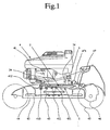
- Fig. 1 is a side view showing a lawn mower 4 attached with a transmission device 1 of the present invention
- Fig. 2 is a bottom view showing a walking type self-traveling lawn mower 4 attached with the transmission device 1 of the present invention
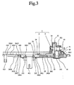
- Fig. 3 is a cross sectional view showing the transmission device 1 of the present example
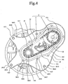
- Fig. 4 is a bottom view showing a configuration of a chain drive mechanism 2
- Fig. 5 is a bottom view showing the chain drive mechanism 2 of another example
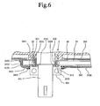
- FIG. 6 is a partial cross sectional view showing an attachment relationship of a drive sprocket 21 with respect to an output shaft 411
- Fig. 7 is an exploded perspective view showing an attachment relationship of the drive sprocket 21 with respect to the output shaft 411
- Fig. 8 is a partial cross sectional view showing an attachment relationship of a drive sprocket 25 of another example with respect to the output shaft 411
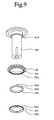
- Fig. 9 is an exploded perspective view showing an attachment relationship of the drive sprocket 25 of another example with respect to the output shaft 411.
- the illustration of an axle of a front wheel, a clutch and brake device, and a lawn mowing blade is omitted in Fig. 2 .
- the transmission device 1 of the present invention has a configuration in which an attachment case 24 incorporating a chain drive mechanism 2 is interposed between a bottom surface of a prime mover 41 and a clutch and brake device 43 of a lawn mowing blade 42, and a rotating direction changing mechanism 3 is projected at the rear surface of a prime mover 41.
- the attachment case 24 is accommodated in a housing 44 with the clutch and brake device 43 and the lawn mowing blade 42. Since the housing 44 becomes large and the vehicle height of the lawn mower 4 needs to be raised when the attachment case 24 becomes thick, the attachment case 24 is desirably thin.
- the thickness allowed between the bottom surface of the prime mover 41 and the clutch and brake device 43 of the lawn mowing blade 42 is smaller than or equal to 30mm.
- the attachment case 24 of the present example can be configured at about 15mm.
- the transmission device 1 of the present example thus can be attached to the existing lawn mower 4 without the necessity to replace the housing 44 or change the design.
- the rotating power output from the rotating direction changing mechanism 3 is transmitted with an auxiliary output shaft 33 and a transmission shaft 47, which are coupled with a universal joint 471, and said transmission shaft 47 coupled to a reducing mechanism 46 of a drive wheels 45.
- the transmission device 1 of the present invention has the chain drive mechanism 2 configured with a drive sprocket 21, a driven sprocket 22, and a transmission chain 23 accommodated in the flat attachment case 24 fixed to the bottom surface of the prime mover 41, and the rotating direction changing mechanism 3 fixed to the upper surface of the attachment case 24 at immediately above the driven sprocket 22.
- the attachment case 24 of the present example is constituted by an upper surface case 241 fixed to the bottom surface of the prime mover 41, and a lower surface case 242 fixed to said upper surface case 241.
- the rotating direction changing mechanism 3 is arranged on the upper surface case 241, and is fixed to the prime mover 41 through the upper surface case 241 by fixing the upper surface case 241 to the bottom surface of the prime mover 41.
- the upper surface case 241 is a flat plate material, which surrounds the transmission chain 23 wound around the drive sprocket 21 and the driven sprocket 22 and circling on the same and which has a size or a shape allocated over a wide range with respect to the bottom surface of the prime mower 41, and is formed with an opening 2411 for passing the output shaft 411 of the prime mower 41 projecting out from the bottom surface of the prime mower 41, and a communication hole 2412 for passing a coupling shaft 311 suspended from a drive bevel gear 31 of the rotating direction changing mechanism 3.
- the upper surface case 241 is arranged with an attachment hole at an attachment part 2413 jutting out in four directions with the opening 2411 as the center, and a plurality of connection bolts 2415 communicating with a connection hole 2424 of the lower surface case 242 described below.
- the upper surface case 241 of the present example is fixed to the bottom surface of the prime mover 41 by screw-fitting a stud bolt 413 to a bolt hole 412 with each attachment hole 2414 communicated to the bolt hole 412 formed at the bottom surface of the prime mover 41 and while being applied to the bottom surface of the prime mover 41.
- the housing 44 of the lawn mowing blade 42 is attached to an opposing surface of the prime mover 41 using the stud bolt 413 projecting out from the attachment hole 2414 of the upper surface case 241.
- the opening 2411 of the upper surface case 241 is not sealed with respect to the output shaft 411, so that excessive pressure in the attachment case 24 can escape to the outside from a gap of the opening 2411 and the output shaft 411.
- the upper surface case 241 of the present example pivotally attaches a chain tensioner 231.
- the chain tensioner 231 pushes the inner side of the circling path of the transmission chain 23.
- the chain tensioner 232 may push the outer side of the circling path of the transmission chain 23 by being pivotally attached to the upper surface case 241 (see Fig. 5 ).
- the lower surface case 242 is a flat dish shaped member, which surrounds the transmission chain 23 wound around the drive sprocket 21 and the driven sprocket 22 and circling on the same and which includes a peripheral surface 2422 and a lower surface 2426 having a size or a shape taking into consideration the bulge of the circling path of the transmission chain 23 by the chain tensioner 231, and is formed with an opening 2421 coaxial with the opening 2411 of the upper surface case 241 to pass the output shaft 411 therethrough.
- the chain drive mechanism 2 of the present example accommodates the drive sprocket 21, the driven sprocket 22, and the transmission chain 23 in a range of the depth (height of peripheral surface 2422) of the lower surface case 242.
- the lower surface case 242 of the present example is formed with a connection hole 2424 in plurals at a flange 2324 jutting out from the peripheral surface 2422, and is integrated with the upper surface case 241 by a nut 2427 with the connection hole 2424 communicated to the connection bolt 2415 of the upper surface case 241.
- the opening 2421 of the lower surface case 242 is attached with a seal ring 2425, and slidably contacts the seal ring 2425 with respect to a bearing 431 of the clutch and brake device 43 fitted to the output shaft 411 (see Fig. 6 ).
- the attachment case 24 is in a sealed state other than at the gap of the opening 2411 with respect to the output shaft 411 of the upper surface case 241, and the grease (not illustrated, semisolid or paste lubricant) filled in the attachment case 24 will not leak downward.
- the chain drive mechanism 2 is constituted by winding the transmission chain 23 including a silent chain around the drive sprocket 21 attached to the output shaft 411 and the driven sprocket 22 securely fixed to the coupling shaft 311 suspended from the drive bevel gear 31 of the rotating direction changing mechanism 3 arranged at the upper surface case 241.
- the drive sprocket 21, the driven sprocket 22, and the transmission chain 23 are enveloped with grease filled in the attachment case 24, so that smooth rotation and circling are guaranteed.
- the present example thus uses a silent chain for the transmission chain 23.
- the chain drive mechanism 2 of the present example has a configuration in which the silent chain of lesser noise in circling than the normal chain is enveloped, as the transmission chain 23, with grease along with the drive sprocket 21 and the driven sprocket 22, and accommodated in the attachment case 24, whereby a very quiet circling of the transmission chain 23 can be realized.
- the drive sprocket 21 of the present example is fitted with pressure and attached to the output shaft 411 while being sandwiched by a taper ring 212 and a tightening nut 213, and can be easily detached by loosening the tightening nut 213.
- the taper ring 212 has a substantially cylindrical shape with a male screw 2122 formed at the lower portion of a reverse circular cone shaped outer peripheral surface 2121, and arranged with a slit 2123 dividing the outer peripheral surface 2121 and the male screw 2122 in the peripheral direction, where a stopper 2124 to be hooked at a step difference part 4111 of the output shaft 411 is arranged at the inner peripheral side of the lower edge.
- the drive sprocket 21 is formed with an attachment hole 211 to be externally fitted to the outer peripheral surface 2121 of the taper ring 212.
- the tightening nut 213 is a substantially flat nut having a male screw 2131 formed on the inner peripheral surface, where the upper surface contacts and pushes the drive sprocket 21 upward.
- the attachment procedure of the drive sprocket 21 in the present example is as follows. First, the taper ring 212 is externally fitted to the output shaft 411, the attachment hole 211 of the drive sprocket 21 is then externally fitted to the outer peripheral surface 2121 of the taper ring 212, and the tightening nut 213 is screw-fitted to the male screw 2122 of the taper ring 212. The taper ring 212 is thereby bonded to the output shaft 411 with pressure by the tightening nut 213, and the drive sprocket 21 is sandwiched by the taper ring 212 and the tightening nut 213. The tightening nut 213 can be rotated with a normal tool. The tightening nut 213 positioned at the lower portion of the drive sprocket 21 plays the role of the guide which supports the transmission chain 23 wound around the drive sprocket 21 from downward.
- the drive sprocket 25 can be removably attached to the output shaft 411 by pushing the taper ring 252 into a gap between the attachment hole 251 of the drive sprocket 25 and the output shaft 411 by a tightening nut 253.
- the taper ring 252 has a circular ring shape so as to be inserted into the gap between the attachment hole of the drive sprocket 25 externally fitted to the output shaft 411 and the output shaft 411, and is arranged with a slit 2522 for dividing a circular cone shaped outer peripheral surface 2521 in the peripheral direction.
- the drive sprocket 25 is arranged with the attachment hole 251 to which the taper ring 252 can be inserted between the output shaft 411 and the drive sprocket 25 itself, and is formed with a female screw 2512 at the inner peripheral surface of an attachment rib 2511 lowering towards the lower side.
- the tightening nut 253 has a flat circular ring shape having the male screw 2531 formed on the outer peripheral surface.
- the attachment procedure of the drive sprocket 25 in another example is as follows. First, the attachment hole 251 of the drive sprocket 25 is externally fitted to the output shaft 411, the taper ring 252 is then inserted into the gap between the output shaft 411 and the attachment hole 251 of the drive sprocket 25, and the tightening nut 253 is screw-fitted to the female screw 2512 of the drive sprocket 25.
- the tightening nut 253 then pushes the taper ring 252 upward, so that the taper ring 252 is press-fitted between the output shaft 411 and the attachment hole 251 of the drive sprocket 25, and the drive sprocket 25 is bonded to the output shaft 411 with pressure via the taper ring 252.
- the tightening nut 253 has a flat circular ring shape, and is rotated by a dedicated tool (not shown) to attach to an engagement hole 2532 formed in the tightening nut 253 as it is difficult to be rotated with a normal tool. It has to be screwed into the drive sprocket 25.
- the chain drive mechanism 2 can transmit the rotating power from the drive sprocket 21 to the driven sprocket 22 via the transmission chain 23, and can provide the function of the reducing mechanism by setting the gear ratio of the driven sprocket 22 with respect to the drive sprocket 21 to greater than one.
- the chain drive mechanism 2 of the present example reduces the rotating power of about 3000rpm output from the output shaft 411 to about 2000rpm by setting the gear ratio to 1.5, and transmits the same to the drive bevel gear 31 of the rotating direction changing mechanism 3.
- the reduction ratio by the chain drive mechanism 2 can be easily increased by miniaturizing the drive sprocket 21 in accordance with the output shaft 411, and enlarging the driven sprocket 22 in the range of the bottom surface of the prime mover 41 or the range of the housing 44 of the lawn mowing blade 42.
- the reduction can also be realized with the rotating direction changing mechanism 3 as hereinafter described, a means for increasing the gear ratio of the chain drive mechanism 2 is usable when a high reduction ratio is needed.
- the rotating direction changing mechanism 3 is constituted by the drive bevel gear 31, the driven bevel gear 32, and the auxiliary output shaft 33 accommodated in a gear case 34 fixed to the upper surface case 241 described above.
- the drive bevel gear 31 has the suspending coupling shaft 311 supported by an upper bearing 35 held by the upper surface case 241 and a lower bearing 36 held by the lower surface case 242, where the coupling shaft 311 is suspended through the communication hole 2412 formed in the upper surface case 241, and the driven sprocket 22 is securely fixed to the coupling shaft 311.
- the drive bevel gear 31 rotates horizontally at a constant speed with the driven sprocket 22.
- the driven bevel gear 32 has the rotation shaft 321 supported by the gear case 34, and rotates vertically while meshing with the drive bevel gear 31.
- the auxiliary output shaft 33 is the portion obtained by extending one end of the rotation shaft 321 to project out from the gear case 34.
- the transmission shaft 47 is coupled to an end of the auxiliary output shaft 33 via the universal joint 471 (see Fig. 1 and Fig. 2 ).
- the rotating direction changing mechanism 3 transmits the rotating power between the drive bevel gear 31 and the driven bevel gear 32, which mesh with each other, and provides the function of the reducing mechanism by setting the gear ratio of the driven bevel gear 32 with respect to the drive bevel gear 31 to greater than one.
- the rotating direction changing mechanism 3 of the present example reduces the rotating power of about 2000rpm transmitted from the drive sprocket 22 to about 600rpm by setting the gear ratio to 3.3, and outputs the same from the auxiliary output shaft 33 to be transmitted to the transmission shaft 47 (see Fig. 1 and Fig. 2 )
- the reduction of the rotating power can also be achieved with the chain drive mechanism 2, which can be combined with the reduction by the rotating direction changing mechanism 3 so that the transmission device 1 of the present example obtains a large reduction ratio as a whole.
- a separate reducing mechanism 46 is necessary for the drive wheels 45 since the rotating power output from the auxiliary output shaft 33 still has a high rotation number (about 600rpm in the above) to directly drive the drive wheels 45, but the reducing mechanism 46 of the drive wheels 45 can be miniaturized as the rotating power can be reduced by the transmission device 1 of the present invention. This is a secondary effect of the present invention.
Abstract
Description
- The present invention relates to a walking type self-traveling lawn mower with a transmission device.
- The walking type self-traveling lawn mower (hereinafter abbreviated as "lawn mower") rotates a lawn mowing blade and drive wheels and thereby self-travels with the rotating power from a prime mover. A worker can walk and operate as holding an operation handle on a vehicle body of the lawn mower for stating-up and stopping the drive wheels, and changing direction to left or right. Such lawn mower branches the rotating power from the prime mover to the lawn mowing blade and the drive wheels. With respect to an output shaft of the prime mover, the lawn mowing blade is directly connected to said output shaft via a clutch and a brake device. The drive wheels are connected to the said output shaft via a transmission device for branching the rotating power from the output shaft.
- The transmission device can be roughly classified according to the system branching the rotating power from the output shaft. Specifically, one is a transmission device of a configuration in which a shaft is connected to an auxiliary output shaft operating in conjunction with an output shaft of the prime mover (hereafter referred to as "shaft drive system", shown in
patent document 1 and patent document 2), and another is a transmission device of a configuration in which a drive pulley is attached to an output shaft of the prime mover, a driven pulley is attached to drive wheels, and a transmission belt is bridged across said drive pulley and said driven pulley (hereafter referred to as "belt drive system", shown inpatent document 3 and patent document 4). The usage of them differs depending on various situations, but generally, the large and expensive lawn mower adopts the shaft drive system, and the small and inexpensive lawn mower adopts the belt drive system. - As seen in
patent document 1, in the transmission device of the shaft drive system, a reducing mechanism incorporated in the prime mover has an auxiliary output shaft, where the reduced rotating power is retrieved from the auxiliary output shaft, and the retrieved reduced rotating power is transmitted to the drive wheels by a transmission shaft coupled to the auxiliary output shaft and an universal joint. As seen inpatent document 2, a configuration may also be adopted in which the auxiliary output shaft is connected to the output shaft via a simple worm gear mechanism, and then the auxiliary output shaft and the reducing mechanism arranged in the drive wheels are connected. In this case, the reducing mechanism arranged in the drive wheels may sometimes be a hydraulic stepless speed change device. - In the transmission device of the belt drive system, the drive pulley is attached to the output shaft of the prime mover, the driven pulley is attached directly to the drive wheels or to the reducing mechanism arranged in the drive wheels, and the transmission belt is wound around the drive pulley and the driven pulley so that rotating power is transmitted by the transmission belt. When winding the transmission belt around the driven pulley directly attached to the drive wheels, the radius ratio of the drive pulley and the driven pulley becomes the reduction ratio. As seen in
patent document 3, the transmission device of the belt drive system has a feature in that the rotating power of the output shaft rotating horizontally can be converted to the rotating power of the drive wheels rotating vertically by twisting the transmission belt. -
- Patent document 1: Japanese Published Utility Model Publication No.
59-062735 - Patent document 2: Japanese Published Utility Model Publication No.
63-009819 - Patent document 3: Japanese Published Utility Model Publication No.
58-105824 - Patent document 4: Japanese Published Utility Model Publication No.
02-031422 -
US 2003/182917 A1 discloses a walking type self-travelling lawn mower for branching a rotating power from an output shaft vertically projected from a prime mover mounted on a vehicle body and transmitting the rotating power to drive wheels, comprising a chain drive mechanism constituted by a drive sprocket fitted to the output shaft and rotating horizontally, a driven sprocket connected to the rotating direction changing mechanism and rotating horizontally and a transmission chain wound around said sprockets, and a rotating direction changing mechanism comprising an output shaft. -
JP 05 280604 A -
US 2 513 685 A discloses an entire chain drive mechanism mounted in a flat case. -
EP 1 219 156 A1 discloses a rotating direction changing mechanism constituted by a drive bevel gear, and a driven bevel gear meshed with the drive bevel gear. - It is an object of the invention to provide a walking type self-travelling lawn mower with a transmission device that prevents damage to parts of the lawn mower when the transmission device breaks.
The transmission device of the shaft drive system has also advantages in that the durability of the transmission shaft is high, maintenance is hardly needed, and the rotating power can be reliably transmitted, but has disadvantages in that the configuration is complicating as there is a need for a dedicated prime mover equipped with the auxiliary output shaft or to arrange the auxiliary output shaft on a general purpose prime mover, and the manufacturing cost is high, and thus it is normally used only in a relatively expensive or large lawn mower. The transmission device of the belt drive system, on the other hand, can be easily configured by simply attaching the drive pulley to the output shaft of the prime mover while using the general purpose prime mover, and the manufacturing cost is low, and thus it can be widely used in a relatively inexpensive or small lawn mower. The fact that products with low manufacturing cost tend to be widespread is also true to lawn mowers and thus the lawn mowers being sold are predominantly belt drive system. One of the factors that create the difference in manufacturing costs of the two systems is that the manufactured quantity of the dedicated prime mover of the shaft drive system is small. - Therefore, the transmission device of belt drive system which can use the general purpose prime mover, which configuration is simple, and which manufacturing cost is low appears to be superior, but the transmission device of the belt drive system has a fatal problem in that the durability of the transmission belt is low. A cause thereof is that the transmission belt slides with respect to the drive pulley or the driven pulley and wears out. The sliding of the transmission belt can be suppressed by using a tension pulley, but in this case, the tension pulley bends the circling path of the transmission belt thereby degrading the transmission belt. Thus, in any case, the durability of the transmission belt lowers by wear or bend.
- The above-mentioned problem is solved by a walking type self-travelling lawn mower having the features disclosed in
claim 1. - As a result of the examination, there is developer a transmission device of a walking type self-traveling lawn mower for branching a rotating power from an output shaft vertically projected from a prime mover mounted on a vehicle body and attached with a horizontally rotating lawn mowing blade and transmitting said rotating power to a drive wheels, the transmission device of the walking type self-traveling lawn mower including a chain drive mechanism and a rotating direction changing mechanism; wherein the chain drive mechanism is constituted by winding a transmission chain around a drive sprocket fitted to the output shaft and rotating horizontally and a driven sprocket connected to the rotating direction changing mechanism and rotating horizontally; and the rotating direction changing mechanism is constituted by a drive bevel gear coaxial with the driven sprocket rotating horizontally, a driven bevel gear meshed with the drive bevel gear rotating vertically, and an auxiliary output shaft coaxial with the driven bevel gear rotating vertically.
- The transmission device of the present invention is a hybrid transmission device enabling the use of the shaft drive system on the general purpose prime mover of the transmission device of the belt drive system by combining the chain drive mechanism which can be referred to as the chain drive system as opposed to the belt drive system, and the rotating direction changing mechanism. That is, the chain drive mechanism of the chain drive system transmits the rotating power of horizontal rotation from the output shaft of the prime mover up to the position not interfering with the prime mover, and the transmission shaft used in the shaft drive system transmits the rotating power from the position where the rotating power of horizontal rotation is converted to vertical rotation by the rotating direction changing mechanism. The auxiliary output shaft and the drive wheels are connected with the transmission shaft of shaft drive system, and various means known in the prior art are used to connect the transmission shaft to the drive wheels. The transmission shaft then may be connected to a reducing mechanism arranged in the drive wheels.
- Since the lawn mower using the transmission device of the belt drive system has the transmission belt interposed between the prime mover and the lawn mowing blade, the transmission belt can be easily replaced with the transmission chain used in the transmission device of the present invention. This means that the transmission device of the present invention can be easily replaced with an already installed transmission device of the belt drive system. Furthermore, the transmission chain used in the transmission device of the present invention merely needs to transmit the rotating power up to the position that does not interfere with the prime mover, or normally, the rotating direction changing mechanism arranged on the side surface of the prime mover. Therefore, the circling path of the transmission chain can be shortened up to about 1/3 to 1/2 of the length of conventional transmission belt. Since the transmission chain itself is strong compared to the transmission belt, it has an advantage in that the durability as power transmitting means is high. Moreover, the transmission chain is less likely to degrade over ages and can transmit stable rotating power, and the following rotating direction changing mechanism can also transmit stable rotating power, and thus the transmission of the rotating power stabilizes in the transmission device of the present invention as a whole.
- Since the transmission chain of the chain drive mechanism has a short circling path, as described above, the chain drive mechanism of the present invention has an inner side of the circling path of the transmission chain pressed by a chain tensioner to prevent loosening of the transmission chain in order to stabilize the transmission of the rotating power. The tensioner may be pivotally attached to an attachment case (to be hereinafter described) for accommodating the transmission chain, and is pressed against the transmission chain from the inner periphery that meshes with the drive sprocket and the driven sprocket.
- In the chain drive mechanism, the drive sprocket is attached to the output shaft without particularly working the output shaft of the prime mover. Therefore in the chain drive mechanism, the drive sprocket is attached to the output shaft by forming a male screw at a lower portion of a reverse circular cone shaped outer peripheral surface of a taper ring, externally fitting the taper ring, having a slit dividing the outer peripheral surface and the male screw in the peripheral direction, to the output shaft of the prime mover, externally fitting the drive sprocket to the outer peripheral surface of the taper ring, screw fitting a tightening nut having a female screw formed on an inner peripheral surface to the male screw of the taper ring, bonding the taper ring with pressure to the output shaft by the screw-fitting of the tightening nut, and sandwiching the drive sprocket with the taper ring and the tightening nut.
- Also, in the chain drive mechanism, the drive sprocket can be attached to the output shaft by externally fitting a drive sprocket having a female screw formed at a lower portion of an inner peripheral surface to the output shaft, inserting a circular cone shaped taper ring having a slit dividing a circular cone shaped outer peripheral surface in the peripheral direction between the output shaft of the prime mover and the inner peripheral surface of the drive sprocket, screw fitting a tightening nut having a male screw formed on an outer peripheral surface to the female screw of the drive sprocket, and fitting the taper ring with pressure between said output shaft of the prime mover and said inner peripheral surface of the drive sprocket by the screw-fitting of said tightening nut. In the above described configuration, the drive sprocket is merely fixed with pressure to the output shaft via the taper ring, and in the previously described configuration, the taper ring is merely fitted with pressure between the output shaft of the prime mover and the inner peripheral surface of the drive sprocket. Therefore, when the transmission device breaks, these configurations are advantageous in that the drive sprocket goes around in circles, thereby the output shaft, the prime mover and other parts are prevented from being damaged when the transmission device breaks. Furthermore, it is also advantageous in that the transmission device itself including the drive sprocket can be easily detached from the lawn mower by loosening the tightening nut.
- When using the transmission device of the present invention, the reducing mechanism may be arranged in the drive wheels to reduce the rotation number of the rotating power, as previously described. However, if the chain drive mechanism also serves as a reducing mechanism by setting a gear ratio of the driven sprocket with respect to the drive sprocket to greater than one, the rotation number of the rotating power can be reduced at the gear ratio, that is, the percentage of the reduction ratio. The practical gear ratio in the chain drive mechanism may be about five at maximum since the rotation number of the rotating power can also be reduced by the rotating direction changing mechanism as hereinafter described.
- The transmission chain of the chain drive mechanism merely needs to be a conventionally known general chain, but a silent chain is preferably used. The silent chain has an advantage of having silence property of silently circling compared to the conventional general chain, thereby contributing to enhancement in silence of the transmission device and furthermore in silence of the lawn mower, so that the lawn mower equipped with the transmission device of the present invention can be used in residential areas and the like.
- The chain drive mechanism and the rotating direction changing mechanism constituting the transmission device of the present invention may be attached to the vehicle body or the prime mover of the lawn mower as separate bodies. However, the attachment of the transmission device with respect to the vehicle body or the prime mover is facilitated with the transmission device in which the chain drive mechanism and the rotating direction changing mechanism are integrated by having the chain drive mechanism accommodate the drive sprocket, the driven sprocket, and the transmission chain in a flat attachment case fixed to the vehicle body or the prime mover, and fixing the rotating direction changing mechanism on an upper surface of the attachment case, immediately above the driven sprocket. When a chain tensioner is applied to the chain drive mechanism, the chain tensioner is also accommodated in the attachment case. The attachment case has a function of protecting the chain drive mechanism and specifying the positional relationship of the chain drive mechanism and the rotating direction changing mechanism.
- A bolt hole for fixing the housing of the lawn mowing blade to the vehicle body or the prime mover may be used to fix the attachment case to the vehicle body or the prime mover. For instance, the attachment case may be fixed to the vehicle body or the prime mover by communicating the attachment hole formed in the attachment case and the attachment hole formed in the housing of the lawn mowing blade, and passing the attachment bolt through both attachment holes and screw-fitting the passed bolt to the bolt hole of the vehicle body or the prime mover. The attachment case can also be fixed to the vehicle body or the prime mover by screw-fitting a stud bolt (tap-end bolt) in the bolt hole formed in the vehicle body or the prime mover, and passing the tap-end bolt through the attachment hole formed in the attachment case and the attachment hole formed in the housing of the lawn mowing blade and tightening with a nut. In either case, the pass-through of the attachment bolt and the tightening of the nut with respect to the stud bolt are facilitated if the upper surface of a attachment base is projected from the lower surface, and the attachment hole is formed in the upper surface.
- The attachment case normally has a sealed structure in an aim of protecting the chain drive mechanism. Thus, if the lubricant is filled in the attachment case, the circling of the transmission chain becomes smooth, and rust prevention of the drive sprocket, the driven sprocket and the transmission chain can be achieved. However, if the attachment case is completely sealed, the pressure in the attachment case increases by the circling of the transmission chain, whereby the lubricant leaks out, and in the worst case, the attachment case may burst. In this case, provision of a separately arranged pressure escape hole or a separately arranged relief valve is usable while completely sealing the attachment case. However, easy, convenient, and practical configuration of the attachment case is such where an opening enabling the output shaft of the prime mover to pass therethrough is formed on the upper surface and the lower surface, the opening formed on the upper surface passes the output shaft without attaching a seal ring, the opening formed on the lower surface attaches a seal ring, and the seal ring slidably contacts to the output shaft and closes the opening; and the attachment case in the sealed state is filled with semisolid or paste lubricant.
- The attachment case realizes a sealed state by forming an opening on the upper surface and the lower surface to pass the output shaft through the attachment case accommodating the transmission chain etc., wherein the opening formed in the upper surface merely passing the output shaft and pressing the upper surface against the vehicle body or the prime mover, the opening formed on the lower surface being attached with the seal ring and slidably contacting the seal ring to the output shaft and closing the same. In this sealed state, the pressure can escape from the opening of the upper surface when the pressure in the attachment case becomes high. Thus, the lubricant filled in the attachment case is suppressed from moving downward with the pressure escape, and is prevented from leaking out along the output shaft to which the seal ring merely slidably contacts. However, since the attachment case overturns with the vehicle body in maintenance and cleaning of the lawn mowing blade, the present invention fills the attachment case with semisolid or paste lubricant for the lubricant that does not leak out when the attachment case is overturned.
- The auxiliary output shaft of the rotating direction changing mechanism can be projected from the driven bevel gear slightly tilting in the up or down direction according to the mesh relationship of the drive bevel gear and the driven bevel gear, but the positional relationship of the auxiliary output shaft, the drive wheels and the reducing mechanism arranged in the drive wheels when the transmission device is actually installed is not uniform. Therefore, it is preferable that the rotating direction changing mechanism has a universal joint arranged on the auxiliary output shaft, and the transmission shaft is connected to the universal joint. If the rotating direction changing mechanism is installed on the rear surface side of the prime mover with respect to the advancing direction of the lawn mower, and the auxiliary output shaft is projected backward from the rotating direction changing mechanism, the auxiliary output shaft arranged with the universal joint can be connected with the existing transmission shaft, and the transmission device of the shaft drive system can be replaced with the transmission device of the present invention. In addition, the rotating direction changing mechanism also serves as a reducing mechanism by setting a gear ratio of the driven bevel gear with respect to the drive bevel gear to greater than one. The practical gear ratio in the rotating direction changing mechanism may be about five at maximum.
- The present invention resolves the problem of the durability of the transmission belt of the belt drive system while basically adopting the transmission device of the belt drive system capable of using a general purpose prime mover. The present invention also resolves the problem of reliably transmitting the rotating power at the similar level of the shaft drive system by enabling the use of the shaft drive system on the general purpose prime mover of the transmission device of the belt drive system by adopting a hybrid system combining the chain drive mechanism referred to as the chain drive system as opposed to the belt drive system and the rotating direction changing mechanism. This means that the shaft drive system can be adopted using the transmission device of the present invention, whereby the manufacturing cost of the lawn mower adopting the shaft drive system can be reduced.
- Since the chain drive mechanism merely circles the transmission chain with high mechanical strength on a short circling path, the transmission of the rotating power becomes stable and reliable. The transmission of the rotating power by the transmission chain becomes more stable and reliable with the simultaneous use of the chain tensioner and the use of the silent chain. The configuration of attaching the drive sprocket to the output shaft using the taper ring and the tightening nut eliminates working of the output shaft, and prevents the influence of defects on the vehicle body or the prime mover (fail safe) by having the drive sprocket go around in circles when defects occur in the transmission device. The attachment case realizes unity as the transmission device, and facilitates the handling of the transmission device. The attachment case merely has the upper surface formed with the opening for passing the output shaft pressed against the vehicle body or the prime mover, so that the pressure in the attachment case can escape from the opening.
- The rotating direction changing mechanism enables the use of the transmission device of the shaft drive system of the prior art in the present invention by arranging the universal joint on the auxiliary output shaft. In addition, the chain drive mechanism sets the gear ratio of the driven sprocket with respect to the drive sprocket to greater than one, and the rotating direction changing mechanism sets the gear ratio of the driven bevel gear with respect to the drive bevel gear to greater than one so as to respectively serve as the reducing mechanism, and reduce the rotation speed in a step-wise manner in transmission of the rotating power. Thus the drive wheels is simply arranged with a compact reducing mechanism suppressed with the reduction ratio, thereby contributing to lighter weight and miniaturization of the lawn mower. Therefore, the transmission device of the present invention not only enables the use of the shaft drive system while using the general purpose prime mover, but also has an effect of improving the transmission mode itself of the rotating power.
-
-
Fig. 1 is a side view showing a walking type self-traveling lawn mower attached with a transmission device of the present invention; -
Fig. 2 is a bottom view showing the walking type self-traveling lawn mower attached with the transmission device of the present invention; -
Fig. 3 is a cross sectional view showing the transmission device of the present example; -
Fig. 4 is a bottom view showing a configuration of a chain drive mechanism; -
Fig. 5 is a bottom view showing a chain drive mechanism of another example; -
Fig. 6 is a partial cross sectional view showing an attachment relationship of a drive sprocket with respect to an output shaft; -
Fig. 7 is an exploded perspective view showing an attachment relationship of the drive sprocket with respect to the output shaft; -
Fig. 8 is a partial cross sectional view showing an attachment relationship of another example of a drive sprocket with respect to the output shaft; and -
Fig. 9 is an exploded perspective view showing an attachment relationship of another example of the drive sprocket with respect to the output shaft. -
- 1
- transmission device
- 2
- chain drive mechanism
- 21
- drive sprocket
- 212
- taper ring
- 213
- tightening nut
- 22
- driven sprocket
- 23
- transmission chain
- 24
- attachment case
- 241
- upper surface case
- 242
- lower surface case
- 2425
- seal ring
- 25
- drive sprocket
- 252
- taper ring
- 253
- tightening nut
- 3
- rotating direction changing mechanism
- 31
- drive bevel gear
- 32
- driven bevel gear
- 33
- auxiliary output shaft
- 4
- walking type self-traveling lawn mower
- 41
- prime mover
- 411
- output shaft
- 42
- lawn mowing blade
- 45
- drive wheels
- 47
- transmission shaft
- 471
- universal joint
- The embodiments of the present invention will be hereinafter described with reference to the drawings. The embodiments depicted in
figs 5 ,8 and9 and associated description pages 10-11, 22, 26 and 30-31 do not form part of the invention but represent background art useful for understanding the invention.Fig. 1 is a side view showing a lawn mower 4 attached with atransmission device 1 of the present invention,Fig. 2 is a bottom view showing a walking type self-traveling lawn mower 4 attached with thetransmission device 1 of the present invention,Fig. 3 is a cross sectional view showing thetransmission device 1 of the present example,Fig. 4 is a bottom view showing a configuration of achain drive mechanism 2,Fig. 5 is a bottom view showing thechain drive mechanism 2 of another example,Fig. 6 is a partial cross sectional view showing an attachment relationship of adrive sprocket 21 with respect to anoutput shaft 411,Fig. 7 is an exploded perspective view showing an attachment relationship of thedrive sprocket 21 with respect to theoutput shaft 411,Fig. 8 is a partial cross sectional view showing an attachment relationship of adrive sprocket 25 of another example with respect to theoutput shaft 411, andFig. 9 is an exploded perspective view showing an attachment relationship of thedrive sprocket 25 of another example with respect to theoutput shaft 411. For the sake of convenience of the explanation, the illustration of an axle of a front wheel, a clutch and brake device, and a lawn mowing blade is omitted inFig. 2 . - As shown in
Fig. 1 orFig. 2 , thetransmission device 1 of the present invention has a configuration in which anattachment case 24 incorporating achain drive mechanism 2 is interposed between a bottom surface of aprime mover 41 and a clutch andbrake device 43 of alawn mowing blade 42, and a rotatingdirection changing mechanism 3 is projected at the rear surface of aprime mover 41. Theattachment case 24 is accommodated in ahousing 44 with the clutch andbrake device 43 and thelawn mowing blade 42. Since thehousing 44 becomes large and the vehicle height of the lawn mower 4 needs to be raised when theattachment case 24 becomes thick, theattachment case 24 is desirably thin. - In the lawn mower 4 to which the present invention can be applied, the thickness allowed between the bottom surface of the
prime mover 41 and the clutch andbrake device 43 of thelawn mowing blade 42 is smaller than or equal to 30mm. Theattachment case 24 of the present example can be configured at about 15mm. Thetransmission device 1 of the present example thus can be attached to the existing lawn mower 4 without the necessity to replace thehousing 44 or change the design. The rotating power output from the rotatingdirection changing mechanism 3 is transmitted with anauxiliary output shaft 33 and atransmission shaft 47, which are coupled with auniversal joint 471, and saidtransmission shaft 47 coupled to a reducingmechanism 46 of adrive wheels 45. - As shown in
Fig. 3 orFig. 4 , thetransmission device 1 of the present invention has thechain drive mechanism 2 configured with adrive sprocket 21, a drivensprocket 22, and atransmission chain 23 accommodated in theflat attachment case 24 fixed to the bottom surface of theprime mover 41, and the rotatingdirection changing mechanism 3 fixed to the upper surface of theattachment case 24 at immediately above the drivensprocket 22. Theattachment case 24 of the present example is constituted by anupper surface case 241 fixed to the bottom surface of theprime mover 41, and alower surface case 242 fixed to saidupper surface case 241. - The rotating
direction changing mechanism 3 is arranged on theupper surface case 241, and is fixed to theprime mover 41 through theupper surface case 241 by fixing theupper surface case 241 to the bottom surface of theprime mover 41. This has an advantage in that the work is reduced as the attachment of thetransmission device 1 merely requires the fixing task of theattachment case 24, and in addition, an advantage in that positioning of the rotatingdirection changing mechanism 3 with respect to thechain drive mechanism 2 incorporated in theattachment case 24 becomes unnecessary. - The
upper surface case 241 is a flat plate material, which surrounds thetransmission chain 23 wound around thedrive sprocket 21 and the drivensprocket 22 and circling on the same and which has a size or a shape allocated over a wide range with respect to the bottom surface of theprime mower 41, and is formed with anopening 2411 for passing theoutput shaft 411 of theprime mower 41 projecting out from the bottom surface of theprime mower 41, and acommunication hole 2412 for passing acoupling shaft 311 suspended from adrive bevel gear 31 of the rotatingdirection changing mechanism 3. Theupper surface case 241 is arranged with an attachment hole at anattachment part 2413 jutting out in four directions with theopening 2411 as the center, and a plurality ofconnection bolts 2415 communicating with aconnection hole 2424 of thelower surface case 242 described below. - Thus, the
upper surface case 241 of the present example is fixed to the bottom surface of theprime mover 41 by screw-fitting astud bolt 413 to abolt hole 412 with eachattachment hole 2414 communicated to thebolt hole 412 formed at the bottom surface of theprime mover 41 and while being applied to the bottom surface of theprime mover 41. Thehousing 44 of thelawn mowing blade 42 is attached to an opposing surface of theprime mover 41 using thestud bolt 413 projecting out from theattachment hole 2414 of theupper surface case 241. Theopening 2411 of theupper surface case 241 is not sealed with respect to theoutput shaft 411, so that excessive pressure in theattachment case 24 can escape to the outside from a gap of theopening 2411 and theoutput shaft 411. In addition, theupper surface case 241 of the present example pivotally attaches achain tensioner 231. Thechain tensioner 231 pushes the inner side of the circling path of thetransmission chain 23. Thechain tensioner 232 may push the outer side of the circling path of thetransmission chain 23 by being pivotally attached to the upper surface case 241 (seeFig. 5 ). - The
lower surface case 242 is a flat dish shaped member, which surrounds thetransmission chain 23 wound around thedrive sprocket 21 and the drivensprocket 22 and circling on the same and which includes aperipheral surface 2422 and alower surface 2426 having a size or a shape taking into consideration the bulge of the circling path of thetransmission chain 23 by thechain tensioner 231, and is formed with anopening 2421 coaxial with theopening 2411 of theupper surface case 241 to pass theoutput shaft 411 therethrough. Thechain drive mechanism 2 of the present example accommodates thedrive sprocket 21, the drivensprocket 22, and thetransmission chain 23 in a range of the depth (height of peripheral surface 2422) of thelower surface case 242. - The
lower surface case 242 of the present example is formed with aconnection hole 2424 in plurals at a flange 2324 jutting out from theperipheral surface 2422, and is integrated with theupper surface case 241 by anut 2427 with theconnection hole 2424 communicated to theconnection bolt 2415 of theupper surface case 241. Theopening 2421 of thelower surface case 242 is attached with aseal ring 2425, and slidably contacts theseal ring 2425 with respect to abearing 431 of the clutch andbrake device 43 fitted to the output shaft 411 (seeFig. 6 ). Theattachment case 24 is in a sealed state other than at the gap of theopening 2411 with respect to theoutput shaft 411 of theupper surface case 241, and the grease (not illustrated, semisolid or paste lubricant) filled in theattachment case 24 will not leak downward. - The
chain drive mechanism 2 is constituted by winding thetransmission chain 23 including a silent chain around thedrive sprocket 21 attached to theoutput shaft 411 and the drivensprocket 22 securely fixed to thecoupling shaft 311 suspended from thedrive bevel gear 31 of the rotatingdirection changing mechanism 3 arranged at theupper surface case 241. Thedrive sprocket 21, the drivensprocket 22, and thetransmission chain 23 are enveloped with grease filled in theattachment case 24, so that smooth rotation and circling are guaranteed. - However, the noise inevitably becomes large with the normal chain as the
drive sprocket 21 rotates at a constant speed (about 3000rpm) which is same as that of theoutput shaft 411. In this regards, the gear drive mechanism is not preferable, though it can be used in the present invention, as the noise becomes larger. The present example thus uses a silent chain for thetransmission chain 23. Thechain drive mechanism 2 of the present example has a configuration in which the silent chain of lesser noise in circling than the normal chain is enveloped, as thetransmission chain 23, with grease along with thedrive sprocket 21 and the drivensprocket 22, and accommodated in theattachment case 24, whereby a very quiet circling of thetransmission chain 23 can be realized. - As seen in
Fig. 6 andFig. 7 , thedrive sprocket 21 of the present example is fitted with pressure and attached to theoutput shaft 411 while being sandwiched by ataper ring 212 and a tighteningnut 213, and can be easily detached by loosening the tighteningnut 213. Thetaper ring 212 has a substantially cylindrical shape with amale screw 2122 formed at the lower portion of a reverse circular cone shaped outerperipheral surface 2121, and arranged with aslit 2123 dividing the outerperipheral surface 2121 and themale screw 2122 in the peripheral direction, where astopper 2124 to be hooked at astep difference part 4111 of theoutput shaft 411 is arranged at the inner peripheral side of the lower edge. Thedrive sprocket 21 is formed with anattachment hole 211 to be externally fitted to the outerperipheral surface 2121 of thetaper ring 212. The tighteningnut 213 is a substantially flat nut having amale screw 2131 formed on the inner peripheral surface, where the upper surface contacts and pushes thedrive sprocket 21 upward. - The attachment procedure of the
drive sprocket 21 in the present example is as follows. First, thetaper ring 212 is externally fitted to theoutput shaft 411, theattachment hole 211 of thedrive sprocket 21 is then externally fitted to the outerperipheral surface 2121 of thetaper ring 212, and the tighteningnut 213 is screw-fitted to themale screw 2122 of thetaper ring 212. Thetaper ring 212 is thereby bonded to theoutput shaft 411 with pressure by the tighteningnut 213, and thedrive sprocket 21 is sandwiched by thetaper ring 212 and the tighteningnut 213. The tighteningnut 213 can be rotated with a normal tool. The tighteningnut 213 positioned at the lower portion of thedrive sprocket 21 plays the role of the guide which supports thetransmission chain 23 wound around thedrive sprocket 21 from downward. - As shown in
Fig. 8 andFig. 9 , thedrive sprocket 25 can be removably attached to theoutput shaft 411 by pushing thetaper ring 252 into a gap between theattachment hole 251 of thedrive sprocket 25 and theoutput shaft 411 by a tighteningnut 253. Thetaper ring 252 has a circular ring shape so as to be inserted into the gap between the attachment hole of thedrive sprocket 25 externally fitted to theoutput shaft 411 and theoutput shaft 411, and is arranged with aslit 2522 for dividing a circular cone shaped outerperipheral surface 2521 in the peripheral direction. Thedrive sprocket 25 is arranged with theattachment hole 251 to which thetaper ring 252 can be inserted between theoutput shaft 411 and thedrive sprocket 25 itself, and is formed with afemale screw 2512 at the inner peripheral surface of anattachment rib 2511 lowering towards the lower side. The tighteningnut 253 has a flat circular ring shape having themale screw 2531 formed on the outer peripheral surface. - The attachment procedure of the
drive sprocket 25 in another example is as follows. First, theattachment hole 251 of thedrive sprocket 25 is externally fitted to theoutput shaft 411, thetaper ring 252 is then inserted into the gap between theoutput shaft 411 and theattachment hole 251 of thedrive sprocket 25, and the tighteningnut 253 is screw-fitted to thefemale screw 2512 of thedrive sprocket 25. The tighteningnut 253 then pushes thetaper ring 252 upward, so that thetaper ring 252 is press-fitted between theoutput shaft 411 and theattachment hole 251 of thedrive sprocket 25, and thedrive sprocket 25 is bonded to theoutput shaft 411 with pressure via thetaper ring 252. The tighteningnut 253 has a flat circular ring shape, and is rotated by a dedicated tool (not shown) to attach to anengagement hole 2532 formed in the tighteningnut 253 as it is difficult to be rotated with a normal tool. It has to be screwed into thedrive sprocket 25. - The
chain drive mechanism 2 can transmit the rotating power from thedrive sprocket 21 to the drivensprocket 22 via thetransmission chain 23, and can provide the function of the reducing mechanism by setting the gear ratio of the drivensprocket 22 with respect to thedrive sprocket 21 to greater than one. Thechain drive mechanism 2 of the present example reduces the rotating power of about 3000rpm output from theoutput shaft 411 to about 2000rpm by setting the gear ratio to 1.5, and transmits the same to thedrive bevel gear 31 of the rotatingdirection changing mechanism 3. - The reduction ratio by the
chain drive mechanism 2 can be easily increased by miniaturizing thedrive sprocket 21 in accordance with theoutput shaft 411, and enlarging the drivensprocket 22 in the range of the bottom surface of theprime mover 41 or the range of thehousing 44 of thelawn mowing blade 42. Although the reduction can also be realized with the rotatingdirection changing mechanism 3 as hereinafter described, a means for increasing the gear ratio of thechain drive mechanism 2 is usable when a high reduction ratio is needed. - As shown in
Fig. 3 , the rotatingdirection changing mechanism 3 is constituted by thedrive bevel gear 31, the drivenbevel gear 32, and theauxiliary output shaft 33 accommodated in agear case 34 fixed to theupper surface case 241 described above. Thedrive bevel gear 31 has the suspendingcoupling shaft 311 supported by anupper bearing 35 held by theupper surface case 241 and alower bearing 36 held by thelower surface case 242, where thecoupling shaft 311 is suspended through thecommunication hole 2412 formed in theupper surface case 241, and the drivensprocket 22 is securely fixed to thecoupling shaft 311. Thus, thedrive bevel gear 31 rotates horizontally at a constant speed with the drivensprocket 22. The drivenbevel gear 32 has therotation shaft 321 supported by thegear case 34, and rotates vertically while meshing with thedrive bevel gear 31. Theauxiliary output shaft 33 is the portion obtained by extending one end of therotation shaft 321 to project out from thegear case 34. Thetransmission shaft 47 is coupled to an end of theauxiliary output shaft 33 via the universal joint 471 (seeFig. 1 andFig. 2 ). - The rotating
direction changing mechanism 3 transmits the rotating power between thedrive bevel gear 31 and the drivenbevel gear 32, which mesh with each other, and provides the function of the reducing mechanism by setting the gear ratio of the drivenbevel gear 32 with respect to thedrive bevel gear 31 to greater than one. The rotatingdirection changing mechanism 3 of the present example reduces the rotating power of about 2000rpm transmitted from thedrive sprocket 22 to about 600rpm by setting the gear ratio to 3.3, and outputs the same from theauxiliary output shaft 33 to be transmitted to the transmission shaft 47 (seeFig. 1 andFig. 2 ) - As described above, the reduction of the rotating power can also be achieved with the
chain drive mechanism 2, which can be combined with the reduction by the rotatingdirection changing mechanism 3 so that thetransmission device 1 of the present example obtains a large reduction ratio as a whole. However, a separate reducingmechanism 46 is necessary for thedrive wheels 45 since the rotating power output from theauxiliary output shaft 33 still has a high rotation number (about 600rpm in the above) to directly drive thedrive wheels 45, but the reducingmechanism 46 of thedrive wheels 45 can be miniaturized as the rotating power can be reduced by thetransmission device 1 of the present invention. This is a secondary effect of the present invention.
Claims (3)
- A walking-type self-traveling lawn mower with a transmission device (1), for branching a rotating power from an output shaft (411) vertically projected from a prime mover (41) mounted on a vehicle body and transmitting the rotating power to drive wheels (45), comprising:a chain drive mechanism (2) and a rotating direction changing mechanism (3); whereinthe chain drive mechanism (2) is constituted by accomodating a drive sprocket (21) fitted to the output shaft (411) and rotating horizontally, a driven sprocket (22) connected to the rotating direction changing mechanism (3) and rotating horizontally, a transmission chain (23) wound around said drive sprocket (21) and said driven sprocket (22), a chain tensioner adapted to press a circling path of the transmission chain (23) from an inner side to prevent loosening of the transmission chain (23) in a flat attachment case (24) fixed to the vehicle body or the prime mover (41); andthe rotating direction changing mechanism (3) is constituted by a drive bevel gear (31) coaxial with the driven sprocket (22) rotating horizontally, a driven bevel gear (32) rotating vertically and meshed with the drive bevel gear (31), and an auxiliary output shaft (33) coaxial with the driven bevel gear (32) and rotating vertically; andthe rotating direction changing mechanism (3) is fixed on an upper surface of the attachment case (24), immediately above the driven sprocket (22); andin the chain drive mechanism (2) the drive sprocket (21) is attached to the output shaft (411), whereina male screw is formed at a lower portion of a reverse circular cone shaped outer peripheral surface of a taper ring (212),the taper ring (212), having a slit dividing the outer peripheral surface and the male screw in the peripheral direction, is externally fitted to the output shaft (411) of the prime mover (41),the drive sprocket (21) is externally fitted to the outer peripheral surface of the taper ring (212),a tightening nut (213) having a female screw formed on an inner peripheral surface is fitted to the male screw of the taper ring (212),the taper ring (212) is bonded with pressure to the output shaft (411) by the screw-fitting of the tightening nut (213), and the drive sprocket (21) is sandwiched with the taper ring (212) and the tightening nut (213).
- The walking type self-traveling lawn mower according to claim 1, wherein the chain drive mechanism (2) uses a silent chain for the transmission chain (23).
- The walking type self-traveling lawn mower according to claim 1 or 2, wherein
the attachment case (24) is constituted by forming an opening enabling the output shaft (411) of the prime mover (41) to pass therethrough on the upper surface and a lower surface, the opening (2411) formed on the upper surface passing the output shaft (411) without attaching a seal ring (2425), the opening (2421) formed on the lower surface (242) attaching the seal ring (2425), and slidably contacting the seal ring (2425) to the output shaft (411) and closing the opening; and the attachment case (24) is filled with semisolid or paste lubricant.
Applications Claiming Priority (2)
| Application Number | Priority Date | Filing Date | Title |
|---|---|---|---|
| JP2006038780 | 2006-02-16 | ||
| PCT/JP2007/052014 WO2007094201A1 (en) | 2006-02-16 | 2007-02-06 | Transmission device of walking type self-traveling lawn mower |
Publications (3)
| Publication Number | Publication Date |
|---|---|
| EP1985169A1 EP1985169A1 (en) | 2008-10-29 |
| EP1985169A4 EP1985169A4 (en) | 2010-06-23 |
| EP1985169B1 true EP1985169B1 (en) | 2012-07-18 |
Family
ID=38371387
Family Applications (1)
| Application Number | Title | Priority Date | Filing Date |
|---|---|---|---|
| EP07713843A Active EP1985169B1 (en) | 2006-02-16 | 2007-02-06 | Transmission device of walking type self-traveling lawn mower |
Country Status (5)
| Country | Link |
|---|---|
| US (1) | US8047938B2 (en) |
| EP (1) | EP1985169B1 (en) |
| JP (1) | JP5123163B2 (en) |
| CN (1) | CN101389211B (en) |
| WO (1) | WO2007094201A1 (en) |
Families Citing this family (9)
| Publication number | Priority date | Publication date | Assignee | Title |
|---|---|---|---|---|
| JP5676327B2 (en) * | 2011-03-18 | 2015-02-25 | 株式会社マキタ | Power transmission mechanism |
| CN104620755B (en) * | 2015-02-10 | 2017-11-21 | 福建省晋江市三力机车有限公司 | A kind of hay mower running gear durable test device and method |
| US10660253B2 (en) | 2016-03-17 | 2020-05-26 | Kai S. Lee | Twin shaft system for gardening systems |
| JP6887164B2 (en) * | 2016-08-31 | 2021-06-16 | カーツ株式会社 | Lawn mower transmission |
| US10791662B2 (en) * | 2017-05-19 | 2020-10-06 | Kai S. Lee | Twin shaft gardening system |
| US11154009B2 (en) * | 2018-05-03 | 2021-10-26 | Horning Manufacturing, LLC | Single disk rotary forage harvester header |
| WO2020125258A1 (en) * | 2018-12-18 | 2020-06-25 | 苏州宝时得电动工具有限公司 | Lawn mower |
| CN112413062A (en) * | 2020-11-19 | 2021-02-26 | 江苏巨杰机电有限公司 | Three-wheel gear transmission with multiple gear changes |
| CN112664628B (en) * | 2020-12-01 | 2022-03-08 | 机械工业第九设计研究院股份有限公司 | Chain tensioning control structure |
Family Cites Families (23)
| Publication number | Priority date | Publication date | Assignee | Title |
|---|---|---|---|---|
| US2513685A (en) * | 1948-06-21 | 1950-07-04 | Lucius N Smith | Lawn mower |
| US2897645A (en) * | 1958-03-10 | 1959-08-04 | Frederic J Veillette | Lawn mower reversible frictional drive |
| DE3149609C2 (en) | 1981-12-15 | 1985-11-14 | Webasto-Werk W. Baier GmbH & Co, 8035 Gauting | Drive device for an openable sliding cover |
| JPS5962735A (en) | 1982-10-02 | 1984-04-10 | Akebono Brake Ind Co Ltd | Sliding brake shoe for magnetic floating type vehicle |
| JPS5962735U (en) * | 1982-10-20 | 1984-04-25 | 本田技研工業株式会社 | Transmission device in self-propelled lawn mowers |
| JPS61133157A (en) | 1984-12-04 | 1986-06-20 | Hitachi Chem Co Ltd | Liquid atomizer |
| JPH0511404Y2 (en) * | 1985-02-08 | 1993-03-22 | ||
| JPS639819A (en) | 1986-06-30 | 1988-01-16 | Yokogawa Electric Corp | Displacement transducing device |
| JP2684192B2 (en) | 1988-07-20 | 1997-12-03 | 日立電子エンジニアリング株式会社 | CVD apparatus and heater cover position adjusting method |
| US5224552A (en) * | 1991-03-20 | 1993-07-06 | Lee Kai S | Counter-rotating twin shaft system for gardening machines |
| US5353881A (en) * | 1991-03-20 | 1994-10-11 | Lee Kai S | Counter-rotating twin shaft system for gardening machines |
| US5174100A (en) * | 1991-04-08 | 1992-12-29 | Wassenberg Brian E | Combination mower/trimmer apparatus |
| JPH05280604A (en) * | 1992-03-31 | 1993-10-26 | Suzuki Motor Corp | Tensioner device of engine |
| US5377774A (en) * | 1993-02-04 | 1995-01-03 | Hoffco, Inc. | Variable speed drive system |
| JP3195204B2 (en) * | 1995-09-12 | 2001-08-06 | 本田技研工業株式会社 | Drive device for walking machine |
| JP3263707B2 (en) * | 1995-11-10 | 2002-03-11 | 株式会社 神崎高級工機製作所 | Transmission of walking type self-propelled lawn mower |
| JPH09220012A (en) * | 1996-02-15 | 1997-08-26 | Kanzaki Kokyukoki Mfg Co Ltd | Transmission for self-running lawn mower |
| US6155035A (en) * | 1996-05-10 | 2000-12-05 | Merritt, Iii; C. Waverly | Multi-functional lawn mower apparatus for use with an auxiliary apparatus and methods of utilizing the same |
| US5800301A (en) * | 1997-05-09 | 1998-09-01 | Borg-Warner Automotive, Inc. | Chain assembly using formed bushings with inverted teeth |
| JP3750322B2 (en) | 1997-11-14 | 2006-03-01 | 株式会社アテックス | Walking mower |
| JP4607382B2 (en) * | 2000-12-28 | 2011-01-05 | 本田技研工業株式会社 | Walking type work machine |
| US6688095B2 (en) * | 2002-03-28 | 2004-02-10 | The Toro Company | Blade coupler assembly for use with a self-propelled, walk-behind rotary lawn mower |
| US7661503B2 (en) * | 2005-04-07 | 2010-02-16 | Orion Dynamics, Inc. | Vehicle suspension system for stable squat magnitude responses |
-
2007
- 2007-02-06 WO PCT/JP2007/052014 patent/WO2007094201A1/en active Application Filing
- 2007-02-06 CN CN2007800054688A patent/CN101389211B/en active Active
- 2007-02-06 EP EP07713843A patent/EP1985169B1/en active Active
- 2007-02-06 JP JP2008500451A patent/JP5123163B2/en active Active
- 2007-02-06 US US12/223,364 patent/US8047938B2/en active Active
Also Published As
| Publication number | Publication date |
|---|---|
| EP1985169A4 (en) | 2010-06-23 |
| US8047938B2 (en) | 2011-11-01 |
| WO2007094201A1 (en) | 2007-08-23 |
| US20090054184A1 (en) | 2009-02-26 |
| EP1985169A1 (en) | 2008-10-29 |
| CN101389211B (en) | 2010-09-29 |
| JP5123163B2 (en) | 2013-01-16 |
| CN101389211A (en) | 2009-03-18 |
| JPWO2007094201A1 (en) | 2009-07-02 |
Similar Documents
| Publication | Publication Date | Title |
|---|---|---|
| EP1985169B1 (en) | Transmission device of walking type self-traveling lawn mower | |
| US10018265B2 (en) | Power transmission device | |
| CN106907439B (en) | Belt tensioner with seal | |
| EP2628976B1 (en) | Torque fluctuation absorbing device | |
| EP2261531B1 (en) | Gear device | |
| US11131365B2 (en) | Reducer | |
| US10557461B1 (en) | Transmission assembly | |
| US10385963B2 (en) | Power transfer device | |
| US7320384B2 (en) | Gearbox for gardening machine | |
| JP2007203999A (en) | Power transmission for hybrid vehicle | |
| JP5359640B2 (en) | Robot wrist device | |
| CN217539488U (en) | Brake planet carrier | |
| JP4515394B2 (en) | Power transmission device for vehicle | |
| KR20180030981A (en) | Driving Device for Electronic Parking Brake | |
| CN213360988U (en) | Gear box | |
| CN212455429U (en) | Hydraulic transmission | |
| KR20170116792A (en) | Driving Device for Electronic Parking Brake | |
| WO2020145339A1 (en) | Vehicular drive device | |
| US20060191363A1 (en) | Right side motorcycle transmission | |
| KR100799641B1 (en) | Riding rice transplanter | |
| KR20200135162A (en) | Internal-pressure rise prevention structure of speed reducer | |
| JP2019188606A (en) | Cutting machine | |
| CN213361005U (en) | Transmission structure of gearbox output shaft and differential mechanism assembly | |
| CN213360989U (en) | Gearbox and PTO transmission device thereof | |
| CN216382498U (en) | Gear box |
Legal Events
| Date | Code | Title | Description |
|---|---|---|---|
| PUAI | Public reference made under article 153(3) epc to a published international application that has entered the european phase |
Free format text: ORIGINAL CODE: 0009012 |
|
| 17P | Request for examination filed |
Effective date: 20080731 |
|
| AK | Designated contracting states |
Kind code of ref document: A1 Designated state(s): AT BE BG CH CY CZ DE DK EE ES FI FR GB GR HU IE IS IT LI LT LU LV MC NL PL PT RO SE SI SK TR |
|
| A4 | Supplementary search report drawn up and despatched |
Effective date: 20100521 |
|
| RIC1 | Information provided on ipc code assigned before grant |
Ipc: A01D 34/47 20060101ALI20100517BHEP Ipc: A01D 34/68 20060101ALI20100517BHEP Ipc: A01D 34/76 20060101AFI20070924BHEP Ipc: A01D 34/10 20060101ALI20100517BHEP |
|
| 17Q | First examination report despatched |
Effective date: 20110316 |
|
| GRAP | Despatch of communication of intention to grant a patent |
Free format text: ORIGINAL CODE: EPIDOSNIGR1 |
|
| DAX | Request for extension of the european patent (deleted) | ||
| RIN1 | Information on inventor provided before grant (corrected) |
Inventor name: SAKAI, SHIN-ICHI |
|
| GRAS | Grant fee paid |
Free format text: ORIGINAL CODE: EPIDOSNIGR3 |
|
| GRAA | (expected) grant |
Free format text: ORIGINAL CODE: 0009210 |
|
| AK | Designated contracting states |
Kind code of ref document: B1 Designated state(s): AT BE BG CH CY CZ DE DK EE ES FI FR GB GR HU IE IS IT LI LT LU LV MC NL PL PT RO SE SI SK TR |
|
| REG | Reference to a national code |
Ref country code: GB Ref legal event code: FG4D |
|
| REG | Reference to a national code |
Ref country code: CH Ref legal event code: EP |
|
| REG | Reference to a national code |
Ref country code: AT Ref legal event code: REF Ref document number: 566685 Country of ref document: AT Kind code of ref document: T Effective date: 20120815 Ref country code: IE Ref legal event code: FG4D |
|
| REG | Reference to a national code |
Ref country code: DE Ref legal event code: R096 Ref document number: 602007024063 Country of ref document: DE Effective date: 20120913 |
|
| REG | Reference to a national code |
Ref country code: NL Ref legal event code: VDEP Effective date: 20120718 |
|
| REG | Reference to a national code |
Ref country code: AT Ref legal event code: MK05 Ref document number: 566685 Country of ref document: AT Kind code of ref document: T Effective date: 20120718 |
|
| REG | Reference to a national code |
Ref country code: LT Ref legal event code: MG4D Effective date: 20120718 |
|
| PG25 | Lapsed in a contracting state [announced via postgrant information from national office to epo] |
Ref country code: CY Free format text: LAPSE BECAUSE OF FAILURE TO SUBMIT A TRANSLATION OF THE DESCRIPTION OR TO PAY THE FEE WITHIN THE PRESCRIBED TIME-LIMIT Effective date: 20120718 Ref country code: FI Free format text: LAPSE BECAUSE OF FAILURE TO SUBMIT A TRANSLATION OF THE DESCRIPTION OR TO PAY THE FEE WITHIN THE PRESCRIBED TIME-LIMIT Effective date: 20120718 Ref country code: IS Free format text: LAPSE BECAUSE OF FAILURE TO SUBMIT A TRANSLATION OF THE DESCRIPTION OR TO PAY THE FEE WITHIN THE PRESCRIBED TIME-LIMIT Effective date: 20121118 Ref country code: AT Free format text: LAPSE BECAUSE OF FAILURE TO SUBMIT A TRANSLATION OF THE DESCRIPTION OR TO PAY THE FEE WITHIN THE PRESCRIBED TIME-LIMIT Effective date: 20120718 Ref country code: LT Free format text: LAPSE BECAUSE OF FAILURE TO SUBMIT A TRANSLATION OF THE DESCRIPTION OR TO PAY THE FEE WITHIN THE PRESCRIBED TIME-LIMIT Effective date: 20120718 |
|
| PG25 | Lapsed in a contracting state [announced via postgrant information from national office to epo] |
Ref country code: PT Free format text: LAPSE BECAUSE OF FAILURE TO SUBMIT A TRANSLATION OF THE DESCRIPTION OR TO PAY THE FEE WITHIN THE PRESCRIBED TIME-LIMIT Effective date: 20121119 Ref country code: LV Free format text: LAPSE BECAUSE OF FAILURE TO SUBMIT A TRANSLATION OF THE DESCRIPTION OR TO PAY THE FEE WITHIN THE PRESCRIBED TIME-LIMIT Effective date: 20120718 Ref country code: SE Free format text: LAPSE BECAUSE OF FAILURE TO SUBMIT A TRANSLATION OF THE DESCRIPTION OR TO PAY THE FEE WITHIN THE PRESCRIBED TIME-LIMIT Effective date: 20120718 Ref country code: GR Free format text: LAPSE BECAUSE OF FAILURE TO SUBMIT A TRANSLATION OF THE DESCRIPTION OR TO PAY THE FEE WITHIN THE PRESCRIBED TIME-LIMIT Effective date: 20121019 Ref country code: PL Free format text: LAPSE BECAUSE OF FAILURE TO SUBMIT A TRANSLATION OF THE DESCRIPTION OR TO PAY THE FEE WITHIN THE PRESCRIBED TIME-LIMIT Effective date: 20120718 Ref country code: SI Free format text: LAPSE BECAUSE OF FAILURE TO SUBMIT A TRANSLATION OF THE DESCRIPTION OR TO PAY THE FEE WITHIN THE PRESCRIBED TIME-LIMIT Effective date: 20120718 |
|
| PG25 | Lapsed in a contracting state [announced via postgrant information from national office to epo] |
Ref country code: NL Free format text: LAPSE BECAUSE OF FAILURE TO SUBMIT A TRANSLATION OF THE DESCRIPTION OR TO PAY THE FEE WITHIN THE PRESCRIBED TIME-LIMIT Effective date: 20120718 |
|
| PG25 | Lapsed in a contracting state [announced via postgrant information from national office to epo] |
Ref country code: RO Free format text: LAPSE BECAUSE OF FAILURE TO SUBMIT A TRANSLATION OF THE DESCRIPTION OR TO PAY THE FEE WITHIN THE PRESCRIBED TIME-LIMIT Effective date: 20120718 Ref country code: DK Free format text: LAPSE BECAUSE OF FAILURE TO SUBMIT A TRANSLATION OF THE DESCRIPTION OR TO PAY THE FEE WITHIN THE PRESCRIBED TIME-LIMIT Effective date: 20120718 Ref country code: CZ Free format text: LAPSE BECAUSE OF FAILURE TO SUBMIT A TRANSLATION OF THE DESCRIPTION OR TO PAY THE FEE WITHIN THE PRESCRIBED TIME-LIMIT Effective date: 20120718 Ref country code: EE Free format text: LAPSE BECAUSE OF FAILURE TO SUBMIT A TRANSLATION OF THE DESCRIPTION OR TO PAY THE FEE WITHIN THE PRESCRIBED TIME-LIMIT Effective date: 20120718 Ref country code: ES Free format text: LAPSE BECAUSE OF FAILURE TO SUBMIT A TRANSLATION OF THE DESCRIPTION OR TO PAY THE FEE WITHIN THE PRESCRIBED TIME-LIMIT Effective date: 20121029 |
|
| PLBE | No opposition filed within time limit |
Free format text: ORIGINAL CODE: 0009261 |
|
| STAA | Information on the status of an ep patent application or granted ep patent |
Free format text: STATUS: NO OPPOSITION FILED WITHIN TIME LIMIT |
|
| PG25 | Lapsed in a contracting state [announced via postgrant information from national office to epo] |
Ref country code: SK Free format text: LAPSE BECAUSE OF FAILURE TO SUBMIT A TRANSLATION OF THE DESCRIPTION OR TO PAY THE FEE WITHIN THE PRESCRIBED TIME-LIMIT Effective date: 20120718 |
|
| 26N | No opposition filed |
Effective date: 20130419 |
|
| PG25 | Lapsed in a contracting state [announced via postgrant information from national office to epo] |
Ref country code: BG Free format text: LAPSE BECAUSE OF FAILURE TO SUBMIT A TRANSLATION OF THE DESCRIPTION OR TO PAY THE FEE WITHIN THE PRESCRIBED TIME-LIMIT Effective date: 20121018 |
|
| REG | Reference to a national code |
Ref country code: DE Ref legal event code: R097 Ref document number: 602007024063 Country of ref document: DE Effective date: 20130419 |
|
| PG25 | Lapsed in a contracting state [announced via postgrant information from national office to epo] |
Ref country code: MC Free format text: LAPSE BECAUSE OF NON-PAYMENT OF DUE FEES Effective date: 20130228 |
|
| REG | Reference to a national code |
Ref country code: CH Ref legal event code: PL |
|
| PG25 | Lapsed in a contracting state [announced via postgrant information from national office to epo] |
Ref country code: LI Free format text: LAPSE BECAUSE OF NON-PAYMENT OF DUE FEES Effective date: 20130228 Ref country code: CH Free format text: LAPSE BECAUSE OF NON-PAYMENT OF DUE FEES Effective date: 20130228 |
|
| REG | Reference to a national code |
Ref country code: IE Ref legal event code: MM4A |
|
| PG25 | Lapsed in a contracting state [announced via postgrant information from national office to epo] |
Ref country code: IE Free format text: LAPSE BECAUSE OF NON-PAYMENT OF DUE FEES Effective date: 20130206 |
|
| PG25 | Lapsed in a contracting state [announced via postgrant information from national office to epo] |
Ref country code: TR Free format text: LAPSE BECAUSE OF FAILURE TO SUBMIT A TRANSLATION OF THE DESCRIPTION OR TO PAY THE FEE WITHIN THE PRESCRIBED TIME-LIMIT Effective date: 20120718 |
|
| PG25 | Lapsed in a contracting state [announced via postgrant information from national office to epo] |
Ref country code: HU Free format text: LAPSE BECAUSE OF FAILURE TO SUBMIT A TRANSLATION OF THE DESCRIPTION OR TO PAY THE FEE WITHIN THE PRESCRIBED TIME-LIMIT; INVALID AB INITIO Effective date: 20070206 Ref country code: LU Free format text: LAPSE BECAUSE OF NON-PAYMENT OF DUE FEES Effective date: 20130206 |
|
| REG | Reference to a national code |
Ref country code: FR Ref legal event code: PLFP Year of fee payment: 10 |
|
| REG | Reference to a national code |
Ref country code: FR Ref legal event code: PLFP Year of fee payment: 11 |
|
| REG | Reference to a national code |
Ref country code: FR Ref legal event code: PLFP Year of fee payment: 12 |
|
| PGFP | Annual fee paid to national office [announced via postgrant information from national office to epo] |
Ref country code: FR Payment date: 20230215 Year of fee payment: 17 |
|
| PGFP | Annual fee paid to national office [announced via postgrant information from national office to epo] |
Ref country code: IT Payment date: 20230228 Year of fee payment: 17 Ref country code: BE Payment date: 20230220 Year of fee payment: 17 |
|
| PGFP | Annual fee paid to national office [announced via postgrant information from national office to epo] |
Ref country code: DE Payment date: 20240221 Year of fee payment: 18 Ref country code: GB Payment date: 20240220 Year of fee payment: 18 |