EP1984580B1 - An insert for a weep hole opening in a masonry wall - Google Patents
An insert for a weep hole opening in a masonry wall Download PDFInfo
- Publication number
- EP1984580B1 EP1984580B1 EP07700075.0A EP07700075A EP1984580B1 EP 1984580 B1 EP1984580 B1 EP 1984580B1 EP 07700075 A EP07700075 A EP 07700075A EP 1984580 B1 EP1984580 B1 EP 1984580B1
- Authority
- EP
- European Patent Office
- Prior art keywords
- insert
- grate
- screen
- weep hole
- locating member
- Prior art date
- Legal status (The legal status is an assumption and is not a legal conclusion. Google has not performed a legal analysis and makes no representation as to the accuracy of the status listed.)
- Active
Links
Images


Classifications
-
- E—FIXED CONSTRUCTIONS
- E04—BUILDING
- E04B—GENERAL BUILDING CONSTRUCTIONS; WALLS, e.g. PARTITIONS; ROOFS; FLOORS; CEILINGS; INSULATION OR OTHER PROTECTION OF BUILDINGS
- E04B1/00—Constructions in general; Structures which are not restricted either to walls, e.g. partitions, or floors or ceilings or roofs
- E04B1/62—Insulation or other protection; Elements or use of specified material therefor
- E04B1/70—Drying or keeping dry, e.g. by air vents
- E04B1/7069—Drying or keeping dry, e.g. by air vents by ventilating
-
- E—FIXED CONSTRUCTIONS
- E04—BUILDING
- E04B—GENERAL BUILDING CONSTRUCTIONS; WALLS, e.g. PARTITIONS; ROOFS; FLOORS; CEILINGS; INSULATION OR OTHER PROTECTION OF BUILDINGS
- E04B1/00—Constructions in general; Structures which are not restricted either to walls, e.g. partitions, or floors or ceilings or roofs
- E04B1/62—Insulation or other protection; Elements or use of specified material therefor
- E04B1/70—Drying or keeping dry, e.g. by air vents
-
- E—FIXED CONSTRUCTIONS
- E04—BUILDING
- E04B—GENERAL BUILDING CONSTRUCTIONS; WALLS, e.g. PARTITIONS; ROOFS; FLOORS; CEILINGS; INSULATION OR OTHER PROTECTION OF BUILDINGS
- E04B1/00—Constructions in general; Structures which are not restricted either to walls, e.g. partitions, or floors or ceilings or roofs
- E04B1/62—Insulation or other protection; Elements or use of specified material therefor
- E04B1/70—Drying or keeping dry, e.g. by air vents
- E04B1/7038—Evacuating water from cavity walls, e.g. by using weep holes
- E04B1/7053—Grills for weep holes
-
- E—FIXED CONSTRUCTIONS
- E04—BUILDING
- E04B—GENERAL BUILDING CONSTRUCTIONS; WALLS, e.g. PARTITIONS; ROOFS; FLOORS; CEILINGS; INSULATION OR OTHER PROTECTION OF BUILDINGS
- E04B1/00—Constructions in general; Structures which are not restricted either to walls, e.g. partitions, or floors or ceilings or roofs
- E04B1/62—Insulation or other protection; Elements or use of specified material therefor
- E04B1/72—Pest control
-
- E—FIXED CONSTRUCTIONS
- E04—BUILDING
- E04B—GENERAL BUILDING CONSTRUCTIONS; WALLS, e.g. PARTITIONS; ROOFS; FLOORS; CEILINGS; INSULATION OR OTHER PROTECTION OF BUILDINGS
- E04B1/00—Constructions in general; Structures which are not restricted either to walls, e.g. partitions, or floors or ceilings or roofs
- E04B1/62—Insulation or other protection; Elements or use of specified material therefor
- E04B1/92—Protection against other undesired influences or dangers
- E04B1/94—Protection against other undesired influences or dangers against fire
Definitions
- the present invention relates to an insert for a weep hole opening in a masonry wall and will be described hereinafter with reference to this application.
- the invention is not limited to this application and may also be used in underfloor vents, retaining walls and tilt-up concrete walls.
- weep hole openings are left in mortar joints just above the flashing to allow both ventilation and drainage of the wall cavity between the exterior masonry and the interior wall.
- a weep hole opening is typically formed by the omission of mortar between two adjacent bricks or blocks. The weep hole opening provides ventilation and drainage to keep the wall cavity dry. Without adequate ventilation, dampness causes mildew and rot, which reduce the life of the structure.
- weephole openings vary considerably in size and shape dependent on the skill and care of the tradesmen and the type of brick and type of finishes being applied.
- a problem with weep hole openings situated close to ground level, as are common, is that they can become an entry for rodents and reptiles.
- a problem with weep hole openings around windows or second floors is that they can provide an entry for insects.
- the weep hole opening leading to the wall cavity is an ideal home for bees, wasps and other insects, which themselves create food sources for other pests.
- Another problem associated with weep hole openings is that they provide an entry point for water, particularly during excessive rain or from garden sprinklers.
- Another problem with weep hole openings is that they can allow sparks and firebrands to penetrate a building.
- US Patent No. 4282691 discloses a weep hole device utilising a wick, tube and screen cap.
- US Patent No. 4587891 discloses a ventilating device that incorporates a tubular member and a screened bottom.
- UK Patent No. 2231889A discloses a filter system for allowing drainage from trays in cavity wall.
- US Patent No. 2,709,402 discloses a wall mounted ventilator using a series of parallel prongs as a fixing means.
- Australian Design Registration 131293 appears to disclose a similar device.
- US Patent 5,203,795 discloses a perforated wall plate and sealing gasket with an anchoring device.
- the present applicants' earlier Australian Patent No. 713335 discloses a weep hole device including a hollow plastic body for engagement in a weep hole opening.
- a removable cover is provided over one end of the body to prevent mortar clogging the body during rendering: The cover is removed after rendering is complete and a vermin-proof grate is fitted onto the end of the body in its place.
- a problem with this device is that the grate cannot be installed until after rendering is complete and it is common for tradesmen to misplace the grate.
- weep hole devices such as those mentioned above, are that they often fail as a result of being exposed to high temperatures, for example during bushfires. The failure can occur as a result of the weep hole device igniting and disintegrating, or due to the device melting, which allows fire brands and sparks, as well as vermin and insects, to enter the wall cavity.
- the invention provides an insert for a weep hole opening in a masonry wall, said weep hole insert comprising:
- the predetermined heat flux profile is typical of that generated by a forest fire.
- the locating member is adapted to insulate the screen from radiant heat.
- the locating member is preferably formed from a polymer. More preferably, the polymer is a halogen containing polymer. In a preferred form, the locating member is formed from polyvinylchloride. Preferably, the material forming the locating member is also self-extinguishing.
- the locating member is a grate having a plurality of ventilation apertures to allow air to pass through the air flow conduit. More preferably, the grate is hingedly connected to the body and movable between a closed position for preventing vermin and/or insects from passing through the body and an open position for allowing inspection for the interior of the body.
- the body preferably includes an abutment surface engageable by the grate for holding the grate in the open position.
- the grate includes a recess for locating the screen. Preferably, friction between the screen and the grate retains the screen in the recess.
- the screen is removable. More preferably, the screen is a mesh including cells of less than around 2mm x 2mm. Even more preferably, the cells are around 0.45mm x 0.45mm.
- the screen is formed from a heat conductive material.
- the screen is metal and more preferably is stainless steel.
- a mortar guard releasably snap-lockingly engages the grate to cover the plurality of ventilation apertures to prevent the mortar clogging during rendering.
- the grate is recessed and an outer surface of the mortar guard is flush with the open end of the hollow body.
- the mortar guard includes a slot.
- an insert for a weep hole opening in a masonry wall comprising:
- the body preferably includes an abutment surface engageable by the grate for holding the grate in the open position.
- the weep hole insert also includes a removable screen extending across the conduit, inwardly of the grate, and adapted to prevent fire brands and sparks from passing through the body.
- the screen is a mesh including cells of less than around 2mm x 2mm. Even more preferably, the cells are around 0.45mm x 0.45mm.
- the screen is formed from a heat conductive material.
- the screen is formed from metal and more preferably from stainless steel.
- the screen is preferably located in a recess in the grate. More preferably, friction between the screen and the grate retains the screen in the recess.
- the grate is formed from a material that substantially retains its spatial integrity when exposed to a predetermined heat flux profile and continues thereafter to locate the screen. More preferably, the grate is adapted to insulate the screen from radiant heat.
- the predetermined heat flux profile is typical of that generated by a forest fire.
- the grate is formed from a polymer. More preferably, the polymer is a halogen containing polymer, in a preferred form, the grate is formed from polyvinylchloride. Preferably also, the material forming the grate is self-extinguishing.
- an insert for a weep hole opening in a masonry wall comprising:
- the weep hole insert also includes a removable screen extending across the conduit, inwardly of the grate, and adapted to prevent fire brands and sparks from passing through the body.
- the screen is a mesh including cells of less than around 2mm x 2mm. Even more preferably, the cells are around 0.45mm x 0.45mm.
- the screen is formed from a heat conductive material.
- the screen is formed from metal and more preferably from stainless steel.
- the screen is preferably located in a recess in the grate. More preferably, friction between the screen and the grate retains the screen in the recess.
- the grate is hingedly connected to the body and movable between a closed position for preventing vermin and/or insects from passing through the body and an open position for allowing inspection for the interior of the body.
- the body preferably includes an abutment surface engageable by the grate for holding the grate in the open position.
- the grate is formed from a material that substantially retains its spatial integrity when exposed to a predetermined heat flux profile and continues thereafter to locate the screen. More preferably, the grate is adapted to insulate the screen from radiant heat. Preferably also, the predetermined heat flux profile is typical of that generated by a forest fire.
- the grate is formed from a polymer. More preferably, the polymer is a halogen containing polymer. In a preferred form, the grate is formed from polyvinylchloride. Preferably also, the material forming the grate is self-extinguishing.
- the insert 1 for a weep hole opening in a masonry wall.
- the insert 1 includes a hollow body 2 defining an air flow conduit 3 and including a first open end 4 and a second open end 5.
- a stainless steel mesh screen 6 extends across the conduit 3 near the first open end 4 and is adapted to prevent fire brands and sparks from passing through the body 2 and to absorb heat from the fire brands and sparks.
- the screen 6 includes cells of about 0.45mm x 0.45mm.
- a locating member, in the form of a grate 7, is hingedly connected to the body 2 adjacent the first open end 4.
- the screen 6 is located in a recess 8 in the rear of the grate 7 and friction between the screen 6 and the grate 7 retains the screen 6 in the recess 8.
- the grate 7 is formed from a material that substantially retains its spatial integrity when exposed to the heat flux profile generated by a typical forest fire, such that the grate 7 continues thereafter to locate the screen 6.
- the grate 7 also has a plurality of ventilation apertures 9 to allow air to pass through the air flow conduit 3.
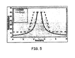
- Figure 5 shows the heat flux profile generated by a typical forest fire. This figure also shows a design heat flux profile based on the typical forest fire profile.
- the grate 7 is moulded from polyvinylchloride, which is self-extinguishing and flame retardant. This material tends to burn and char when exposed to the design heat flux profile shown in Figure 5 , and quickly self-extinguishes once a fire has passed.
- other polymers with flame-retardant characteristics are used, such as other halogen containing polymers or cross-linked polymers.
- the grate 7 is hingedly connected to the body 2 and movable between a closed position for preventing vermin and/or insects from passing through the body 2 and an open position for allowing inspection for the interior of the body 2.
- a closed position for preventing vermin and/or insects from passing through the body 2
- an open position for allowing inspection for the interior of the body 2.
- the grate 7 When the grate 7 is in the open position, as illustrated in Figure 2 , it also permits access to the wall cavity for the placement of insecticides or other treatments.
- the screen 6 is located inwardly of the grate 7 such that the grate 7 insulates the screen 6 from radiant heat outside the grate.
- the grate 7 is recessed with respect to the first open end 4 of the body 2.
- a mortar guard 10 releasably snap-lockingly engages the grate 7 to cover the ventilation apertures 9 to prevent mortar clogging the apertures 9 during rendering.
- the outer surface of the mortar guard 10 is flush with the first open end 4 of the body 2.
- the mortar guard includes a slot 11 engageable by a screwdriver or the like to facilitate its removal from the grate 7, when rendering is complete.
- the body 2 is sized for a snug fit within a weep hole opening of a masonry wall.
- the body 2 includes substantially planar outer surfaces to facilitate adjustment of the position of the weep hole insert 1 within the weep hole opening. Also, the omission of anchors makes it easy to remove and replace the insert 1 if it becomes unserviceable.
- the body 2 includes internal ribs 12 for strengthening its sidewalls against bowing. Also, the body 2 includes an abutment surface 13 engageable by the grate 7 for holding the grate 7 in the open position.
- the mesh screen 6 and the mortar guard 9 are pre-installed in the weep hole insert 1.
- the weep hole insert 1 is placed into the weep hole opening of a wall with the first end 4 directed toward the exterior of the wall and the second end 5 directed toward the wall cavity.
- the grate 7 can be opened to allow the internal ribs 12 to be gripped by long nosed pliers to assist in accurate placement of the weep hole insert 1.
- the grate 7 is closed.
- the mortar guard 10 is removed from the grate 7 to expose the ventilation apertures 9.
- the illustrated weep hole insert 1 is well adapted for use in bushfire prone areas.
- the weep hole insert 1 also facilitates access to the wall cavity for inspections and the placement of insecticides and other treatments.
- the unitary construction of the illustrated insert 1 also overcomes the prior art problem of tradesmen losing the grate.
- the planar outer surface profile of the insert 1 makes it is easy for tradesman to adjust the position of the insert 1 in the weep hole opening and also facilitates removal of damaged weep hole inserts.
Landscapes
- Engineering & Computer Science (AREA)
- Architecture (AREA)
- Physics & Mathematics (AREA)
- Electromagnetism (AREA)
- Civil Engineering (AREA)
- Structural Engineering (AREA)
- Life Sciences & Earth Sciences (AREA)
- Pest Control & Pesticides (AREA)
- Special Wing (AREA)
- Building Environments (AREA)
- Reinforcement Elements For Buildings (AREA)
- Retaining Walls (AREA)
Description
- The present invention relates to an insert for a weep hole opening in a masonry wall and will be described hereinafter with reference to this application. However, the invention is not limited to this application and may also be used in underfloor vents, retaining walls and tilt-up concrete walls.
- In cavity brick or block masonry construction, weep hole openings are left in mortar joints just above the flashing to allow both ventilation and drainage of the wall cavity between the exterior masonry and the interior wall. A weep hole opening is typically formed by the omission of mortar between two adjacent bricks or blocks. The weep hole opening provides ventilation and drainage to keep the wall cavity dry. Without adequate ventilation, dampness causes mildew and rot, which reduce the life of the structure.
- Weephole openings vary considerably in size and shape dependent on the skill and care of the tradesmen and the type of brick and type of finishes being applied. A problem with weep hole openings situated close to ground level, as are common, is that they can become an entry for rodents and reptiles. Similarly, a problem with weep hole openings around windows or second floors is that they can provide an entry for insects. In particular, the weep hole opening leading to the wall cavity is an ideal home for bees, wasps and other insects, which themselves create food sources for other pests. Another problem associated with weep hole openings is that they provide an entry point for water, particularly during excessive rain or from garden sprinklers. Another problem with weep hole openings is that they can allow sparks and firebrands to penetrate a building.
- There have been a number of known approaches which attempt to solve some of the above problems.
-
US Patent No. 4282691 (Risdon ) discloses a weep hole device utilising a wick, tube and screen cap.US Patent No. 4587891 (Kruse ) discloses a ventilating device that incorporates a tubular member and a screened bottom.UK Patent No. 2231889A (Knox -
US Patent No. 2,709,402 (Mahn ) discloses a wall mounted ventilator using a series of parallel prongs as a fixing means. Australian Design Registration 131293 appears to disclose a similar device.US Patent 5,203,795 (Balamut et al ) discloses a perforated wall plate and sealing gasket with an anchoring device. -
US Patent No. 4,102,093 (Harris ) discloses forcing a perforated sheet of aluminium into the weep hole opening and then using a special tool to deform the sheet to the shape of the opening. - The present applicants' earlier Australian Patent No.
713335 - A problem with known weep hole devices, such as those mentioned above, is that they often fail as a result of being exposed to high temperatures, for example during bushfires. The failure can occur as a result of the weep hole device igniting and disintegrating, or due to the device melting, which allows fire brands and sparks, as well as vermin and insects, to enter the wall cavity.
- Another problem with known weep hole devices is that they do not allow easy access to, or inspection of, the wall cavity.
- It is the object of the present invention, at least in its preferred form, to substantially overcome or at least ameliorate one or more of the above disadvantages.
- Accordingly, in a first aspect, the invention provides an insert for a weep hole opening in a masonry wall, said weep hole insert comprising:
- a hollow body defining an air flow conduit and including first and second open ends;
- a screen extending across the conduit near the first open end and adapted to prevent fire brands and sparks from passing through the body; and
- a locating member for locating the screen in the conduit, the locating member being connected to the body adjacent the first open end and characterized in that the locating member is formed from a material that substantially retains its spatial integrity when exposed to a predetermined heat flux profile and continues thereafter to locate the screen.
- More preferably, the predetermined heat flux profile is typical of that generated by a forest fire.
- Preferably, the locating member is adapted to insulate the screen from radiant heat.
- The locating member is preferably formed from a polymer. More preferably, the polymer is a halogen containing polymer. In a preferred form, the locating member is formed from polyvinylchloride. Preferably, the material forming the locating member is also self-extinguishing.
- Preferably, the locating member is a grate having a plurality of ventilation apertures to allow air to pass through the air flow conduit. More preferably, the grate is hingedly connected to the body and movable between a closed position for preventing vermin and/or insects from passing through the body and an open position for allowing inspection for the interior of the body. The body preferably includes an abutment surface engageable by the grate for holding the grate in the open position. In a preferred form, the grate includes a recess for locating the screen. Preferably, friction between the screen and the grate retains the screen in the recess.
- Preferably, the screen is removable. More preferably, the screen is a mesh including cells of less than around 2mm x 2mm. Even more preferably, the cells are around 0.45mm x 0.45mm. In a preferred form, the screen is formed from a heat conductive material. Preferably, the screen is metal and more preferably is stainless steel.
- Preferably, a mortar guard releasably snap-lockingly engages the grate to cover the plurality of ventilation apertures to prevent the mortar clogging during rendering. In a preferred form, the grate is recessed and an outer surface of the mortar guard is flush with the open end of the hollow body. Preferably, the mortar guard includes a slot.
- In another embodiment, there is provided an insert for a weep hole opening in a masonry wall, said weep hole insert comprising:
- a hollow body defining an air flow conduit and including first and second open ends; and
- a grate hingedly connected to the hollow body adjacent the first open end and movable between a closed position for preventing vermin and/or insects from passing through the body and an open position for allowing inspection for the interior of the body, the grate including a plurality of ventilation apertures to allow air to pass through the air flow conduit.
- The body preferably includes an abutment surface engageable by the grate for holding the grate in the open position.
- Preferably, the weep hole insert also includes a removable screen extending across the conduit, inwardly of the grate, and adapted to prevent fire brands and sparks from passing through the body. More preferably, the screen is a mesh including cells of less than around 2mm x 2mm. Even more preferably, the cells are around 0.45mm x 0.45mm. in a preferred form, the screen is formed from a heat conductive material. Preferably, the screen is formed from metal and more preferably from stainless steel. The screen is preferably located in a recess in the grate. More preferably, friction between the screen and the grate retains the screen in the recess.
- In a preferred form, the grate is formed from a material that substantially retains its spatial integrity when exposed to a predetermined heat flux profile and continues thereafter to locate the screen. More preferably, the grate is adapted to insulate the screen from radiant heat.
- Even more preferably, the predetermined heat flux profile is typical of that generated by a forest fire.
- Preferably, the grate is formed from a polymer. More preferably, the polymer is a halogen containing polymer, in a preferred form, the grate is formed from polyvinylchloride. Preferably also, the material forming the grate is self-extinguishing.
- In another embodiment, there is provided an insert for a weep hole opening in a masonry wall, said weep hole insert comprising:
- a hollow body defining an air flow conduit and including first and second open ends; and
- a grate connected to the hollow body adjacent the first open end for preventing vermin and/or insects from passing through the body, the grate including a plurality of ventilation apertures to allow air to pass through the air flow conduit; and a mortar guard releasably engageable with the grate to cover the ventilation apertures during rendering.
- Preferably, the weep hole insert also includes a removable screen extending across the conduit, inwardly of the grate, and adapted to prevent fire brands and sparks from passing through the body. More preferably, the screen is a mesh including cells of less than around 2mm x 2mm. Even more preferably, the cells are around 0.45mm x 0.45mm. In a preferred form, the screen is formed from a heat conductive material. Preferably, the screen is formed from metal and more preferably from stainless steel. The screen is preferably located in a recess in the grate. More preferably, friction between the screen and the grate retains the screen in the recess.
- Preferably, the grate is hingedly connected to the body and movable between a closed position for preventing vermin and/or insects from passing through the body and an open position for allowing inspection for the interior of the body. The body preferably includes an abutment surface engageable by the grate for holding the grate in the open position.
- In a preferred form, the grate is formed from a material that substantially retains its spatial integrity when exposed to a predetermined heat flux profile and continues thereafter to locate the screen. More preferably, the grate is adapted to insulate the screen from radiant heat. Preferably also, the predetermined heat flux profile is typical of that generated by a forest fire.
- Preferably, the grate is formed from a polymer. More preferably, the polymer is a halogen containing polymer. In a preferred form, the grate is formed from polyvinylchloride. Preferably also, the material forming the grate is self-extinguishing.
- A preferred form of the present invention will now be described, by way of an example only, with reference to the accompanying drawings, wherein:
-
Figure 1 is a perspective view of a preferred embodiment of an insert for a weep hole opening according to the invention, showing the grate in a closed position and with the mortar guard in place; -
Figure 2 is a perspective view of the weep hole insert ofFigure 1 , showing the grate in an open position; -
Figure 3 is an exploded perspective view of the weep hole insert ofFigure 1 ; -
Figure 4 is a longitudinal cross-sectional view through the weep hole insert ofFigure 1 ; and -
Figure 5 is a graph of the heat flux profiles for a forest fire and a design fire. - Referring to
Figures 1 to 4 of the drawings, there is shown an insert 1 for a weep hole opening in a masonry wall. The insert 1 includes ahollow body 2 defining anair flow conduit 3 and including a firstopen end 4 and a secondopen end 5. A stainlesssteel mesh screen 6 extends across theconduit 3 near the firstopen end 4 and is adapted to prevent fire brands and sparks from passing through thebody 2 and to absorb heat from the fire brands and sparks. Thescreen 6 includes cells of about 0.45mm x 0.45mm. A locating member, in the form of agrate 7, is hingedly connected to thebody 2 adjacent the firstopen end 4. Thescreen 6 is located in arecess 8 in the rear of thegrate 7 and friction between thescreen 6 and thegrate 7 retains thescreen 6 in therecess 8. Thegrate 7 is formed from a material that substantially retains its spatial integrity when exposed to the heat flux profile generated by a typical forest fire, such that thegrate 7 continues thereafter to locate thescreen 6. Thegrate 7 also has a plurality ofventilation apertures 9 to allow air to pass through theair flow conduit 3. -
Figure 5 shows the heat flux profile generated by a typical forest fire. This figure also shows a design heat flux profile based on the typical forest fire profile. To withstand exposure to the design heat flux profile, thegrate 7 is moulded from polyvinylchloride, which is self-extinguishing and flame retardant. This material tends to burn and char when exposed to the design heat flux profile shown inFigure 5 , and quickly self-extinguishes once a fire has passed. In alternative embodiments, other polymers with flame-retardant characteristics are used, such as other halogen containing polymers or cross-linked polymers. - The
grate 7 is hingedly connected to thebody 2 and movable between a closed position for preventing vermin and/or insects from passing through thebody 2 and an open position for allowing inspection for the interior of thebody 2. When thegrate 7 is in the open position, as illustrated inFigure 2 , it also permits access to the wall cavity for the placement of insecticides or other treatments. When thegrate 7 is in a closed position, as illustrated inFigures 1 and4 , thescreen 6 is located inwardly of thegrate 7 such that thegrate 7 insulates thescreen 6 from radiant heat outside the grate. Also, in the closed position, thegrate 7 is recessed with respect to the firstopen end 4 of thebody 2. - A
mortar guard 10 releasably snap-lockingly engages thegrate 7 to cover theventilation apertures 9 to prevent mortar clogging theapertures 9 during rendering. However, due to thegrate 7 being recessed, the outer surface of themortar guard 10 is flush with the firstopen end 4 of thebody 2. The mortar guard includes a slot 11 engageable by a screwdriver or the like to facilitate its removal from thegrate 7, when rendering is complete. - The
body 2 is sized for a snug fit within a weep hole opening of a masonry wall. Thebody 2 includes substantially planar outer surfaces to facilitate adjustment of the position of the weep hole insert 1 within the weep hole opening. Also, the omission of anchors makes it easy to remove and replace the insert 1 if it becomes unserviceable. Thebody 2 includesinternal ribs 12 for strengthening its sidewalls against bowing. Also, thebody 2 includes anabutment surface 13 engageable by thegrate 7 for holding thegrate 7 in the open position. - The
mesh screen 6 and themortar guard 9 are pre-installed in the weep hole insert 1. In use, the weep hole insert 1 is placed into the weep hole opening of a wall with thefirst end 4 directed toward the exterior of the wall and thesecond end 5 directed toward the wall cavity. Thegrate 7 can be opened to allow theinternal ribs 12 to be gripped by long nosed pliers to assist in accurate placement of the weep hole insert 1. Once the insert 1 has been accurately placed, thegrate 7 is closed. After rendering is completed, themortar guard 10 is removed from thegrate 7 to expose theventilation apertures 9. - It will be appreciated that the illustrated weep hole insert 1 is well adapted for use in bushfire prone areas. The weep hole insert 1 also facilitates access to the wall cavity for inspections and the placement of insecticides and other treatments. The unitary construction of the illustrated insert 1 also overcomes the prior art problem of tradesmen losing the grate. Also, the planar outer surface profile of the insert 1 makes it is easy for tradesman to adjust the position of the insert 1 in the weep hole opening and also facilitates removal of damaged weep hole inserts.
- While the invention has been described with reference to a specific embodiment, it will be appreciated that it may also be embodied in many other forms.
Claims (12)
- An insert (1) for a weep hole opening in a masonry wall, said weep hole insert (1) comprising;a hollow body (2) defining an air flow conduit (3) and including first (4) and second (5) open ends;a screen (6) extending across the conduit (3) near the first open end (4) and adapted to prevent fire brands and sparks from passing through the body (2); anda locating member (7) for locating the screen (6) in the conduit (3), the locating member (7) being connected to the body (2) adjacent the first open end (4) and characterized in that the locating member (7) is formed from a material that substantially retains its spatial integrity when exposed to a predetermined heat flux profile and continues thereafter to locate the screen (6).
- An insert (1) according to claim 1, wherein the locating member (7) is adapted to insulate the screen (6) from radiant heat.
- An insert (1) according to claim 1, wherein the material forming the locating member (7) is self-extinguishing.
- An insert (1) according to claim 1, wherein the locating member (7) is a grate having a plurality of ventilation apertures (9) to allow air to pass through the air flow conduit (3).
- An insert (1) according to claim 4, wherein the grate (7) is hingedly connected to the body (2) and moveable between a closed position for preventing vermin and/or insects from passing through the body (2) and an open position for allowing inspection for the interior of the body (2).
- An insert (1) according to claim 5, wherein the body (2) includes an abutment surface (13) engageable by the grate (7) for holding the grate (7) in the open position.
- An insert (1) according to claim 4, wherein the grate (7) includes a recess (8) for locating the screen (6), and wherein friction between the screen (6) and the grate (7) retains the screen (6) in the recess (8).
- An insert (1) according to claim 1, wherein the screen (6) is a mesh including cells of less than about 2mm x 2mm.
- An insert (1) according to claim 1, wherein the screen (6) is formed from a heat conductive material.
- An insert (1) according to claim 4, wherein a mortar guard (10) releasably snap-lockingly engages the grate (7) to cover the plurality of ventilation apertures (9) to prevent mortar clogging the apertures (9) during rendering.
- An insert (1) according to claim 10, wherein the grate (7) is recessed and an outer surface of the mortar guard (10) is flush with the open end (4) of the hollow body (2).
- An insert (1) according to claim 10, wherein the mortar guard (10) includes a slot (11).
Applications Claiming Priority (2)
| Application Number | Priority Date | Filing Date | Title |
|---|---|---|---|
| AU2006900749A AU2006900749A0 (en) | 2006-02-15 | An insert for a weep hole opening in a masonry wall | |
| PCT/AU2007/000004 WO2007092985A1 (en) | 2006-02-15 | 2007-01-05 | An insert for a weep hole opening in a masonry wall |
Publications (3)
| Publication Number | Publication Date |
|---|---|
| EP1984580A1 EP1984580A1 (en) | 2008-10-29 |
| EP1984580A4 EP1984580A4 (en) | 2012-07-18 |
| EP1984580B1 true EP1984580B1 (en) | 2014-06-11 |
Family
ID=38371098
Family Applications (1)
| Application Number | Title | Priority Date | Filing Date |
|---|---|---|---|
| EP07700075.0A Active EP1984580B1 (en) | 2006-02-15 | 2007-01-05 | An insert for a weep hole opening in a masonry wall |
Country Status (13)
| Country | Link |
|---|---|
| US (1) | US8171677B2 (en) |
| EP (1) | EP1984580B1 (en) |
| JP (1) | JP2009526931A (en) |
| KR (1) | KR20080091758A (en) |
| CN (1) | CN101356327A (en) |
| AU (1) | AU2007215369B2 (en) |
| CA (1) | CA2629033C (en) |
| ES (1) | ES2491221T3 (en) |
| GB (1) | GB2448999A (en) |
| NZ (1) | NZ567674A (en) |
| RU (1) | RU2008118168A (en) |
| WO (1) | WO2007092985A1 (en) |
| ZA (1) | ZA200803841B (en) |
Families Citing this family (16)
| Publication number | Priority date | Publication date | Assignee | Title |
|---|---|---|---|---|
| AU2013211506B2 (en) * | 2008-07-01 | 2017-08-24 | John Noel Flint | Weep hole insert and handle |
| US9823904B2 (en) | 2014-12-18 | 2017-11-21 | International Business Machines Corporation | Managed assertions in an integrated development environment |
| US9747082B2 (en) | 2014-12-18 | 2017-08-29 | International Business Machines Corporation | Optimizing program performance with assertion management |
| US9703552B2 (en) | 2014-12-18 | 2017-07-11 | International Business Machines Corporation | Assertions based on recently changed code |
| US9678855B2 (en) | 2014-12-30 | 2017-06-13 | International Business Machines Corporation | Managing assertions while compiling and debugging source code |
| US10653904B2 (en) | 2017-12-02 | 2020-05-19 | M-Fire Holdings, Llc | Methods of suppressing wild fires raging across regions of land in the direction of prevailing winds by forming anti-fire (AF) chemical fire-breaking systems using environmentally clean anti-fire (AF) liquid spray applied using GPS-tracking techniques |
| US11865394B2 (en) | 2017-12-03 | 2024-01-09 | Mighty Fire Breaker Llc | Environmentally-clean biodegradable water-based concentrates for producing fire inhibiting and fire extinguishing liquids for fighting class A and class B fires |
| US20240157180A1 (en) | 2021-02-04 | 2024-05-16 | Mighty Fire Breaker Llc | Method of and kit for installing and operating a wildfire defense spraying system on a property parcel for proactively spraying environmentally-clean liquid fire inhibitor thereover to inhibit fire ignition and flame spread caused by wind-driven wildfire embers |
| US11865390B2 (en) | 2017-12-03 | 2024-01-09 | Mighty Fire Breaker Llc | Environmentally-clean water-based fire inhibiting biochemical compositions, and methods of and apparatus for applying the same to protect property against wildfire |
| US12594448B2 (en) | 2019-06-22 | 2026-04-07 | Mighty Fire Breaker Llc | Environmentally-clean aqueous-based fire extinguishing biochemical liquid concentrates for mixing with proportioned quantities of water to produce fire extinguishing water streams |
| US11826592B2 (en) | 2018-01-09 | 2023-11-28 | Mighty Fire Breaker Llc | Process of forming strategic chemical-type wildfire breaks on ground surfaces to proactively prevent fire ignition and flame spread, and reduce the production of smoke in the presence of a wild fire |
| WO2019241839A1 (en) * | 2018-06-19 | 2019-12-26 | John Noel Flint | Weep hole insert |
| AU2020245707B2 (en) * | 2019-03-22 | 2026-01-08 | John Noel Flint | Pest barrier |
| US11911643B2 (en) | 2021-02-04 | 2024-02-27 | Mighty Fire Breaker Llc | Environmentally-clean fire inhibiting and extinguishing compositions and products for sorbing flammable liquids while inhibiting ignition and extinguishing fire |
| US12599797B2 (en) | 2020-03-01 | 2026-04-14 | Mighty Fire Breaker Llc | Environmentally-clean fire inhibiting and extinguishing compositions and products for sorbing flammable liquids while inhibiting ignition and extinguishing fire |
| US12616859B2 (en) | 2021-02-04 | 2026-05-05 | Mighty Fire Breaker Llc | Method of and system for defending home building projects from wildfire during and after construction on property located within a wildfire urban interface (WUI) region |
Family Cites Families (28)
| Publication number | Priority date | Publication date | Assignee | Title |
|---|---|---|---|---|
| US2709402A (en) | 1952-01-10 | 1955-05-31 | Edward A Malm | Ventilator |
| US3257929A (en) * | 1964-03-02 | 1966-06-28 | William C Kortvely | Weephole ventilator |
| US3429084A (en) * | 1967-07-10 | 1969-02-25 | Ben Brewer | Insect-proof weep hole |
| US4102093A (en) | 1977-10-25 | 1978-07-25 | Harris William F | Insect control system |
| DE3243034A1 (en) * | 1982-11-22 | 1984-05-30 | Hermann Dipl Ing Moehlenkamp | Moulding for protecting ventilation slots |
| DK161846C (en) * | 1987-05-08 | 1992-02-03 | Dalum Larsen Flemming | VENTILATION STUD FOR WALL. |
| US5203795A (en) | 1991-10-17 | 1993-04-20 | Balamut Jay W | Weephole ventilator and insect guard |
| US6023892A (en) * | 1992-04-02 | 2000-02-15 | Sourlis; Tom | Combination flashing and mortar and debris collection device and system |
| US5274968A (en) * | 1992-05-15 | 1994-01-04 | Jorge Pardo | Building block for use with flashing and arrangement for weeping condensation |
| US5598673A (en) * | 1994-01-18 | 1997-02-04 | Atkins; Mark R. | Masonry cavity wall air space and weeps obstruction prevention system |
| AU713335B2 (en) | 1996-01-12 | 1999-12-02 | John Noel Flint | Weep hole former |
| US5718086A (en) * | 1996-06-10 | 1998-02-17 | Dunn; George A. | Method and apparatus for continuous soffit venting |
| US5918427A (en) * | 1996-10-04 | 1999-07-06 | Vanderwerf; Pieter A. | Termite shield for permeable sheathing |
| NZ330412A (en) * | 1997-05-20 | 1999-03-29 | Watertight Products Aust Pty L | Dual wall drainage assembly comprising an elongate element formed as a channel |
| DE29812054U1 (en) * | 1998-07-07 | 1998-11-26 | Hummel, Heinz, 49196 Bad Laer | Grid element for joint ventilation |
| US6044594A (en) * | 1998-09-18 | 2000-04-04 | Desselle; Douglas P. | Weep hole barrier |
| US6176048B1 (en) * | 1999-06-28 | 2001-01-23 | Bruce B. Berger | Weep hole screen device and method |
| US6474031B2 (en) * | 2000-03-08 | 2002-11-05 | Dale Phillips | Weephole drainage aid and pest barrier |
| US6360493B1 (en) * | 2000-06-07 | 2002-03-26 | Ignacio Torres, III | Weep hole insect barrier |
| US6662504B2 (en) * | 2001-04-18 | 2003-12-16 | Norbert V. Krogstad | Flashing and weep/vent system for a masonry wall |
| US6796100B1 (en) * | 2001-12-12 | 2004-09-28 | Dominick Venezia | Roof venting and cover assembly |
| US6875102B2 (en) * | 2002-09-13 | 2005-04-05 | John J. Achen | Moisture resistant wall vent |
| US20090019793A1 (en) * | 2003-05-02 | 2009-01-22 | Huber Jr Edmund Burke | Weep hole screen |
| US20050066599A1 (en) * | 2003-09-30 | 2005-03-31 | Kimble John F. | Weep hole insert |
| US20050262785A1 (en) * | 2004-05-26 | 2005-12-01 | Alexander Ernest E | Masonry wall vent |
| US7128643B2 (en) * | 2004-06-01 | 2006-10-31 | Aci Air Technologies, Llc | Removable vent having a filter for use in a building foundation |
| US7685778B2 (en) * | 2007-06-04 | 2010-03-30 | Edell James J | Rodent guard |
| US7877946B1 (en) * | 2008-05-22 | 2011-02-01 | Illinois Products Corporation | Weep vent |
-
2007
- 2007-01-05 RU RU2008118168/03A patent/RU2008118168A/en unknown
- 2007-01-05 CN CNA2007800014303A patent/CN101356327A/en active Pending
- 2007-01-05 US US12/095,759 patent/US8171677B2/en active Active
- 2007-01-05 WO PCT/AU2007/000004 patent/WO2007092985A1/en not_active Ceased
- 2007-01-05 JP JP2008554562A patent/JP2009526931A/en active Pending
- 2007-01-05 KR KR1020087012996A patent/KR20080091758A/en not_active Withdrawn
- 2007-01-05 GB GB0808236A patent/GB2448999A/en not_active Withdrawn
- 2007-01-05 EP EP07700075.0A patent/EP1984580B1/en active Active
- 2007-01-05 CA CA2629033A patent/CA2629033C/en active Active
- 2007-01-05 ES ES07700075.0T patent/ES2491221T3/en active Active
- 2007-01-05 AU AU2007215369A patent/AU2007215369B2/en active Active
- 2007-01-05 NZ NZ567674A patent/NZ567674A/en unknown
-
2008
- 2008-05-06 ZA ZA200803841A patent/ZA200803841B/en unknown
Also Published As
| Publication number | Publication date |
|---|---|
| US20080276556A1 (en) | 2008-11-13 |
| CN101356327A (en) | 2009-01-28 |
| EP1984580A1 (en) | 2008-10-29 |
| US8171677B2 (en) | 2012-05-08 |
| ZA200803841B (en) | 2009-02-25 |
| EP1984580A4 (en) | 2012-07-18 |
| GB2448999A (en) | 2008-11-05 |
| WO2007092985A1 (en) | 2007-08-23 |
| ES2491221T3 (en) | 2014-09-05 |
| AU2007215369B2 (en) | 2008-03-13 |
| NZ567674A (en) | 2011-06-30 |
| AU2007215369A1 (en) | 2007-08-23 |
| JP2009526931A (en) | 2009-07-23 |
| RU2008118168A (en) | 2010-03-20 |
| GB0808236D0 (en) | 2008-06-11 |
| KR20080091758A (en) | 2008-10-14 |
| CA2629033C (en) | 2013-11-26 |
| CA2629033A1 (en) | 2007-08-23 |
Similar Documents
| Publication | Publication Date | Title |
|---|---|---|
| CA2629033C (en) | An insert for a weep hole opening in a masonry wall | |
| US7823349B2 (en) | Masonry wall vent | |
| US20100120352A1 (en) | Wall Vent | |
| US4587891A (en) | Ventilating device and method for making the same | |
| AU2007237177B2 (en) | An insert for a weep hole opening in a masonry wall | |
| AU2019290030B2 (en) | Weep hole insert | |
| US6746324B2 (en) | Combustion air wall vent | |
| JP2006144497A (en) | Eave ceiling ventilation | |
| US9903108B2 (en) | Weep hole insert system | |
| AU2008271915B2 (en) | An insert for a weep hole opening in a masonry wall | |
| AU762230B2 (en) | Weephole protector | |
| AU713335B2 (en) | Weep hole former | |
| US11684062B2 (en) | Weep hole guard | |
| US20070254585A1 (en) | Block wall vent and method | |
| JP7399496B2 (en) | Eave ventilation structure and eave ventilation components | |
| EP1566499B1 (en) | Wall vent screen | |
| GB2162305A (en) | A ventilator | |
| JP2002227340A (en) | Wall ventilation hardware and ventilation structure |
Legal Events
| Date | Code | Title | Description |
|---|---|---|---|
| PUAI | Public reference made under article 153(3) epc to a published international application that has entered the european phase |
Free format text: ORIGINAL CODE: 0009012 |
|
| 17P | Request for examination filed |
Effective date: 20080507 |
|
| AK | Designated contracting states |
Kind code of ref document: A1 Designated state(s): AT BE BG CH CY CZ DE DK EE ES FI FR GB GR HU IE IS IT LI LT LU LV MC NL PL PT RO SE SI SK TR |
|
| A4 | Supplementary search report drawn up and despatched |
Effective date: 20120619 |
|
| RIC1 | Information provided on ipc code assigned before grant |
Ipc: E04B 1/94 20060101ALI20120613BHEP Ipc: E04B 1/72 20060101AFI20120613BHEP Ipc: E04B 1/70 20060101ALI20120613BHEP |
|
| DAX | Request for extension of the european patent (deleted) | ||
| 17Q | First examination report despatched |
Effective date: 20120907 |
|
| GRAP | Despatch of communication of intention to grant a patent |
Free format text: ORIGINAL CODE: EPIDOSNIGR1 |
|
| INTG | Intention to grant announced |
Effective date: 20140130 |
|
| GRAJ | Information related to disapproval of communication of intention to grant by the applicant or resumption of examination proceedings by the epo deleted |
Free format text: ORIGINAL CODE: EPIDOSDIGR1 |
|
| GRAS | Grant fee paid |
Free format text: ORIGINAL CODE: EPIDOSNIGR3 |
|
| GRAJ | Information related to disapproval of communication of intention to grant by the applicant or resumption of examination proceedings by the epo deleted |
Free format text: ORIGINAL CODE: EPIDOSDIGR1 |
|
| GRAP | Despatch of communication of intention to grant a patent |
Free format text: ORIGINAL CODE: EPIDOSNIGR1 |
|
| GRAP | Despatch of communication of intention to grant a patent |
Free format text: ORIGINAL CODE: EPIDOSNIGR1 |
|
| GRAS | Grant fee paid |
Free format text: ORIGINAL CODE: EPIDOSNIGR3 |
|
| RBV | Designated contracting states (corrected) |
Designated state(s): AT BE BG CY CZ DE DK EE ES FI FR GB GR HU IS IT LT LV NL PL PT RO SE SI SK TR |
|
| GRAA | (expected) grant |
Free format text: ORIGINAL CODE: 0009210 |
|
| INTG | Intention to grant announced |
Effective date: 20140415 |
|
| AK | Designated contracting states |
Kind code of ref document: B1 Designated state(s): AT BE BG CY CZ DE DK EE ES FI FR GB GR HU IS IT LT LV NL PL PT RO SE SI SK TR |
|
| REG | Reference to a national code |
Ref country code: GB Ref legal event code: FG4D |
|
| REG | Reference to a national code |
Ref country code: AT Ref legal event code: REF Ref document number: 672342 Country of ref document: AT Kind code of ref document: T Effective date: 20140715 |
|
| REG | Reference to a national code |
Ref country code: DE Ref legal event code: R096 Ref document number: 602007037097 Country of ref document: DE Effective date: 20140724 |
|
| REG | Reference to a national code |
Ref country code: ES Ref legal event code: FG2A Ref document number: 2491221 Country of ref document: ES Kind code of ref document: T3 Effective date: 20140905 |
|
| PG25 | Lapsed in a contracting state [announced via postgrant information from national office to epo] |
Ref country code: FI Free format text: LAPSE BECAUSE OF FAILURE TO SUBMIT A TRANSLATION OF THE DESCRIPTION OR TO PAY THE FEE WITHIN THE PRESCRIBED TIME-LIMIT Effective date: 20140611 Ref country code: LT Free format text: LAPSE BECAUSE OF FAILURE TO SUBMIT A TRANSLATION OF THE DESCRIPTION OR TO PAY THE FEE WITHIN THE PRESCRIBED TIME-LIMIT Effective date: 20140611 Ref country code: GR Free format text: LAPSE BECAUSE OF FAILURE TO SUBMIT A TRANSLATION OF THE DESCRIPTION OR TO PAY THE FEE WITHIN THE PRESCRIBED TIME-LIMIT Effective date: 20140912 |
|
| REG | Reference to a national code |
Ref country code: NL Ref legal event code: VDEP Effective date: 20140611 |
|
| REG | Reference to a national code |
Ref country code: AT Ref legal event code: MK05 Ref document number: 672342 Country of ref document: AT Kind code of ref document: T Effective date: 20140611 |
|
| REG | Reference to a national code |
Ref country code: LT Ref legal event code: MG4D |
|
| PG25 | Lapsed in a contracting state [announced via postgrant information from national office to epo] |
Ref country code: SE Free format text: LAPSE BECAUSE OF FAILURE TO SUBMIT A TRANSLATION OF THE DESCRIPTION OR TO PAY THE FEE WITHIN THE PRESCRIBED TIME-LIMIT Effective date: 20140611 Ref country code: LV Free format text: LAPSE BECAUSE OF FAILURE TO SUBMIT A TRANSLATION OF THE DESCRIPTION OR TO PAY THE FEE WITHIN THE PRESCRIBED TIME-LIMIT Effective date: 20140611 |
|
| PG25 | Lapsed in a contracting state [announced via postgrant information from national office to epo] |
Ref country code: EE Free format text: LAPSE BECAUSE OF FAILURE TO SUBMIT A TRANSLATION OF THE DESCRIPTION OR TO PAY THE FEE WITHIN THE PRESCRIBED TIME-LIMIT Effective date: 20140611 Ref country code: PT Free format text: LAPSE BECAUSE OF FAILURE TO SUBMIT A TRANSLATION OF THE DESCRIPTION OR TO PAY THE FEE WITHIN THE PRESCRIBED TIME-LIMIT Effective date: 20141013 Ref country code: CZ Free format text: LAPSE BECAUSE OF FAILURE TO SUBMIT A TRANSLATION OF THE DESCRIPTION OR TO PAY THE FEE WITHIN THE PRESCRIBED TIME-LIMIT Effective date: 20140611 Ref country code: RO Free format text: LAPSE BECAUSE OF FAILURE TO SUBMIT A TRANSLATION OF THE DESCRIPTION OR TO PAY THE FEE WITHIN THE PRESCRIBED TIME-LIMIT Effective date: 20140611 Ref country code: SK Free format text: LAPSE BECAUSE OF FAILURE TO SUBMIT A TRANSLATION OF THE DESCRIPTION OR TO PAY THE FEE WITHIN THE PRESCRIBED TIME-LIMIT Effective date: 20140611 |
|
| PG25 | Lapsed in a contracting state [announced via postgrant information from national office to epo] |
Ref country code: AT Free format text: LAPSE BECAUSE OF FAILURE TO SUBMIT A TRANSLATION OF THE DESCRIPTION OR TO PAY THE FEE WITHIN THE PRESCRIBED TIME-LIMIT Effective date: 20140611 Ref country code: NL Free format text: LAPSE BECAUSE OF FAILURE TO SUBMIT A TRANSLATION OF THE DESCRIPTION OR TO PAY THE FEE WITHIN THE PRESCRIBED TIME-LIMIT Effective date: 20140611 Ref country code: IS Free format text: LAPSE BECAUSE OF FAILURE TO SUBMIT A TRANSLATION OF THE DESCRIPTION OR TO PAY THE FEE WITHIN THE PRESCRIBED TIME-LIMIT Effective date: 20141011 Ref country code: PL Free format text: LAPSE BECAUSE OF FAILURE TO SUBMIT A TRANSLATION OF THE DESCRIPTION OR TO PAY THE FEE WITHIN THE PRESCRIBED TIME-LIMIT Effective date: 20140611 |
|
| REG | Reference to a national code |
Ref country code: DE Ref legal event code: R097 Ref document number: 602007037097 Country of ref document: DE |
|
| PLBE | No opposition filed within time limit |
Free format text: ORIGINAL CODE: 0009261 |
|
| STAA | Information on the status of an ep patent application or granted ep patent |
Free format text: STATUS: NO OPPOSITION FILED WITHIN TIME LIMIT |
|
| PG25 | Lapsed in a contracting state [announced via postgrant information from national office to epo] |
Ref country code: DK Free format text: LAPSE BECAUSE OF FAILURE TO SUBMIT A TRANSLATION OF THE DESCRIPTION OR TO PAY THE FEE WITHIN THE PRESCRIBED TIME-LIMIT Effective date: 20140611 |
|
| 26N | No opposition filed |
Effective date: 20150312 |
|
| REG | Reference to a national code |
Ref country code: DE Ref legal event code: R097 Ref document number: 602007037097 Country of ref document: DE Effective date: 20150312 |
|
| PG25 | Lapsed in a contracting state [announced via postgrant information from national office to epo] |
Ref country code: BE Free format text: LAPSE BECAUSE OF FAILURE TO SUBMIT A TRANSLATION OF THE DESCRIPTION OR TO PAY THE FEE WITHIN THE PRESCRIBED TIME-LIMIT Effective date: 20140611 |
|
| PG25 | Lapsed in a contracting state [announced via postgrant information from national office to epo] |
Ref country code: SI Free format text: LAPSE BECAUSE OF FAILURE TO SUBMIT A TRANSLATION OF THE DESCRIPTION OR TO PAY THE FEE WITHIN THE PRESCRIBED TIME-LIMIT Effective date: 20140611 |
|
| REG | Reference to a national code |
Ref country code: FR Ref legal event code: PLFP Year of fee payment: 10 |
|
| REG | Reference to a national code |
Ref country code: FR Ref legal event code: PLFP Year of fee payment: 11 |
|
| PGFP | Annual fee paid to national office [announced via postgrant information from national office to epo] |
Ref country code: FR Payment date: 20161109 Year of fee payment: 11 |
|
| PGFP | Annual fee paid to national office [announced via postgrant information from national office to epo] |
Ref country code: ES Payment date: 20161109 Year of fee payment: 11 |
|
| PGFP | Annual fee paid to national office [announced via postgrant information from national office to epo] |
Ref country code: DE Payment date: 20161109 Year of fee payment: 11 |
|
| PG25 | Lapsed in a contracting state [announced via postgrant information from national office to epo] |
Ref country code: HU Free format text: LAPSE BECAUSE OF FAILURE TO SUBMIT A TRANSLATION OF THE DESCRIPTION OR TO PAY THE FEE WITHIN THE PRESCRIBED TIME-LIMIT; INVALID AB INITIO Effective date: 20070105 Ref country code: BG Free format text: LAPSE BECAUSE OF FAILURE TO SUBMIT A TRANSLATION OF THE DESCRIPTION OR TO PAY THE FEE WITHIN THE PRESCRIBED TIME-LIMIT Effective date: 20140611 |
|
| PG25 | Lapsed in a contracting state [announced via postgrant information from national office to epo] |
Ref country code: CY Free format text: LAPSE BECAUSE OF FAILURE TO SUBMIT A TRANSLATION OF THE DESCRIPTION OR TO PAY THE FEE WITHIN THE PRESCRIBED TIME-LIMIT Effective date: 20140611 |
|
| PGFP | Annual fee paid to national office [announced via postgrant information from national office to epo] |
Ref country code: IT Payment date: 20170125 Year of fee payment: 11 |
|
| PG25 | Lapsed in a contracting state [announced via postgrant information from national office to epo] |
Ref country code: TR Free format text: LAPSE BECAUSE OF FAILURE TO SUBMIT A TRANSLATION OF THE DESCRIPTION OR TO PAY THE FEE WITHIN THE PRESCRIBED TIME-LIMIT Effective date: 20140611 |
|
| REG | Reference to a national code |
Ref country code: DE Ref legal event code: R119 Ref document number: 602007037097 Country of ref document: DE |
|
| PG25 | Lapsed in a contracting state [announced via postgrant information from national office to epo] |
Ref country code: DE Free format text: LAPSE BECAUSE OF NON-PAYMENT OF DUE FEES Effective date: 20180801 Ref country code: FR Free format text: LAPSE BECAUSE OF NON-PAYMENT OF DUE FEES Effective date: 20180131 |
|
| REG | Reference to a national code |
Ref country code: FR Ref legal event code: ST Effective date: 20180928 |
|
| PG25 | Lapsed in a contracting state [announced via postgrant information from national office to epo] |
Ref country code: IT Free format text: LAPSE BECAUSE OF NON-PAYMENT OF DUE FEES Effective date: 20180105 |
|
| REG | Reference to a national code |
Ref country code: ES Ref legal event code: FD2A Effective date: 20190730 |
|
| PG25 | Lapsed in a contracting state [announced via postgrant information from national office to epo] |
Ref country code: ES Free format text: LAPSE BECAUSE OF NON-PAYMENT OF DUE FEES Effective date: 20180106 |
|
| PGFP | Annual fee paid to national office [announced via postgrant information from national office to epo] |
Ref country code: GB Payment date: 20251103 Year of fee payment: 20 |