EP1983857B1 - Belt latch for a safety belt - Google Patents
Belt latch for a safety belt Download PDFInfo
- Publication number
- EP1983857B1 EP1983857B1 EP07703179A EP07703179A EP1983857B1 EP 1983857 B1 EP1983857 B1 EP 1983857B1 EP 07703179 A EP07703179 A EP 07703179A EP 07703179 A EP07703179 A EP 07703179A EP 1983857 B1 EP1983857 B1 EP 1983857B1
- Authority
- EP
- European Patent Office
- Prior art keywords
- belt
- clamping element
- bending
- main body
- latch
- Prior art date
- Legal status (The legal status is an assumption and is not a legal conclusion. Google has not performed a legal analysis and makes no representation as to the accuracy of the status listed.)
- Active
Links
- 238000005452 bending Methods 0.000 claims abstract 13
- 210000001331 nose Anatomy 0.000 claims description 2
- 230000003014 reinforcing effect Effects 0.000 claims 2
- 239000002184 metal Substances 0.000 description 7
- 230000035484 reaction time Effects 0.000 description 2
- 235000014676 Phragmites communis Nutrition 0.000 description 1
- 230000009286 beneficial effect Effects 0.000 description 1
- 210000000481 breast Anatomy 0.000 description 1
- 230000001419 dependent effect Effects 0.000 description 1
- 230000000694 effects Effects 0.000 description 1
- 238000005538 encapsulation Methods 0.000 description 1
- 238000001125 extrusion Methods 0.000 description 1
- 238000010438 heat treatment Methods 0.000 description 1
- 238000003780 insertion Methods 0.000 description 1
- 230000037431 insertion Effects 0.000 description 1
- 238000004519 manufacturing process Methods 0.000 description 1
- 239000000463 material Substances 0.000 description 1
- 238000000034 method Methods 0.000 description 1
- 239000006223 plastic coating Substances 0.000 description 1
- 230000008092 positive effect Effects 0.000 description 1
Images

Classifications
-
- A—HUMAN NECESSITIES
- A44—HABERDASHERY; JEWELLERY
- A44B—BUTTONS, PINS, BUCKLES, SLIDE FASTENERS, OR THE LIKE
- A44B11/00—Buckles; Similar fasteners for interconnecting straps or the like, e.g. for safety belts
- A44B11/25—Buckles; Similar fasteners for interconnecting straps or the like, e.g. for safety belts with two or more separable parts
- A44B11/2503—Safety buckles
- A44B11/2546—Details
- A44B11/2553—Attachment of buckle to strap
-
- A—HUMAN NECESSITIES
- A44—HABERDASHERY; JEWELLERY
- A44B—BUTTONS, PINS, BUCKLES, SLIDE FASTENERS, OR THE LIKE
- A44B11/00—Buckles; Similar fasteners for interconnecting straps or the like, e.g. for safety belts
- A44B11/25—Buckles; Similar fasteners for interconnecting straps or the like, e.g. for safety belts with two or more separable parts
- A44B11/2503—Safety buckles
- A44B11/2546—Details
- A44B11/2561—Tongue elements
-
- B—PERFORMING OPERATIONS; TRANSPORTING
- B60—VEHICLES IN GENERAL
- B60R—VEHICLES, VEHICLE FITTINGS, OR VEHICLE PARTS, NOT OTHERWISE PROVIDED FOR
- B60R22/00—Safety belts or body harnesses in vehicles
- B60R22/18—Anchoring devices
-
- B—PERFORMING OPERATIONS; TRANSPORTING
- B60—VEHICLES IN GENERAL
- B60R—VEHICLES, VEHICLE FITTINGS, OR VEHICLE PARTS, NOT OTHERWISE PROVIDED FOR
- B60R22/00—Safety belts or body harnesses in vehicles
- B60R22/18—Anchoring devices
- B60R2022/1812—Connections between seat belt and buckle tongue
-
- Y—GENERAL TAGGING OF NEW TECHNOLOGICAL DEVELOPMENTS; GENERAL TAGGING OF CROSS-SECTIONAL TECHNOLOGIES SPANNING OVER SEVERAL SECTIONS OF THE IPC; TECHNICAL SUBJECTS COVERED BY FORMER USPC CROSS-REFERENCE ART COLLECTIONS [XRACs] AND DIGESTS
- Y10—TECHNICAL SUBJECTS COVERED BY FORMER USPC
- Y10T—TECHNICAL SUBJECTS COVERED BY FORMER US CLASSIFICATION
- Y10T24/00—Buckles, buttons, clasps, etc.
- Y10T24/40—Buckles
- Y10T24/4002—Harness
- Y10T24/4012—Clamping
- Y10T24/4019—Sliding part or wedge
-
- Y—GENERAL TAGGING OF NEW TECHNOLOGICAL DEVELOPMENTS; GENERAL TAGGING OF CROSS-SECTIONAL TECHNOLOGIES SPANNING OVER SEVERAL SECTIONS OF THE IPC; TECHNICAL SUBJECTS COVERED BY FORMER USPC CROSS-REFERENCE ART COLLECTIONS [XRACs] AND DIGESTS
- Y10—TECHNICAL SUBJECTS COVERED BY FORMER USPC
- Y10T—TECHNICAL SUBJECTS COVERED BY FORMER US CLASSIFICATION
- Y10T24/00—Buckles, buttons, clasps, etc.
- Y10T24/40—Buckles
- Y10T24/4079—Sliding part of wedge
-
- Y—GENERAL TAGGING OF NEW TECHNOLOGICAL DEVELOPMENTS; GENERAL TAGGING OF CROSS-SECTIONAL TECHNOLOGIES SPANNING OVER SEVERAL SECTIONS OF THE IPC; TECHNICAL SUBJECTS COVERED BY FORMER USPC CROSS-REFERENCE ART COLLECTIONS [XRACs] AND DIGESTS
- Y10—TECHNICAL SUBJECTS COVERED BY FORMER USPC
- Y10T—TECHNICAL SUBJECTS COVERED BY FORMER US CLASSIFICATION
- Y10T24/00—Buckles, buttons, clasps, etc.
- Y10T24/45—Separable-fastener or required component thereof [e.g., projection and cavity to complete interlock]
- Y10T24/45225—Separable-fastener or required component thereof [e.g., projection and cavity to complete interlock] including member having distinct formations and mating member selectively interlocking therewith
- Y10T24/45241—Slot and tab or tongue
-
- Y—GENERAL TAGGING OF NEW TECHNOLOGICAL DEVELOPMENTS; GENERAL TAGGING OF CROSS-SECTIONAL TECHNOLOGIES SPANNING OVER SEVERAL SECTIONS OF THE IPC; TECHNICAL SUBJECTS COVERED BY FORMER USPC CROSS-REFERENCE ART COLLECTIONS [XRACs] AND DIGESTS
- Y10—TECHNICAL SUBJECTS COVERED BY FORMER USPC
- Y10T—TECHNICAL SUBJECTS COVERED BY FORMER US CLASSIFICATION
- Y10T24/00—Buckles, buttons, clasps, etc.
- Y10T24/47—Strap-end-attaching devices
- Y10T24/4736—Buckle connected
Landscapes
- Engineering & Computer Science (AREA)
- Mechanical Engineering (AREA)
- Automotive Seat Belt Assembly (AREA)
- Buckles (AREA)
- Clamps And Clips (AREA)
- Devices For Conveying Motion By Means Of Endless Flexible Members (AREA)
- Compositions Of Macromolecular Compounds (AREA)
- Emergency Lowering Means (AREA)
Abstract
Description
Die Erfindung betrifft eine Gurtzunge für einen Sicherheitsgurt nach dem Oberbegriff des Anspruchs 1.The invention relates to a belt tongue for a safety belt according to the preamble of claim 1.
In einem Dreipunkt-Sicherheitsgurtsystem erstreckt sich das Gurtband von einem oberen zu einem unteren Punkt. Am Sicherheitsgurt ist eine Gurtzunge angeordnet, die mit einem Gurtschloss verbunden werden kann und dann das Gurtband in einen Becken- und einen Oberkörperabschnitt unterteilt. Hierzu weist die Gurtzunge einen Zungengrundkörper mit einer Öse auf, durch welche das Gurtband verläuft.In a three-point seat belt system, the webbing extends from an upper to a lower point. On the seat belt a belt tongue is arranged, which can be connected to a buckle and then subdivides the belt into a pelvic and a torso section. For this purpose, the belt tongue on a tongue body with an eyelet through which the webbing passes.
Es hat sich herausgestellt, dass es im Falle eines Unfalls günstig sein kann, den Beckenabschnitt des Gurtbandes vom Brustabschnitt zu entkoppeln, d.h., das Gurtband im Zungengrundkörper zu blockieren.It has been found that in the event of an accident it may be beneficial to decouple the pelvic portion of the webbing from the breast portion, i.e. to block the webbing in the reed body.
Die gattungsbildende
Bei Rückhaltesystemen in einem Kraftfahrzeug ist es grundsätzlich sehr wichtig, dass sie bei einem Unfall schnell reagieren. Ferner ist es wünschenswert, die Gurtzunge möglichst leicht auszubilden, damit die erforderlichen Retraktorkräfte für den Gurtbandeinzug nicht erhöht werden müssen.In restraint systems in a motor vehicle, it is generally very important that they react quickly in an accident. Furthermore, it is desirable to make the belt tongue as light as possible, so that the required retractor forces for the Gurtbandeinzug need not be increased.
Die vorliegende Aufgabe stellt sich deshalb die Aufgabe, die gattungsgemäße Gurtzunge dahingehend zu verbessern, dass sie ein verbessertes Reaktionsverhalten zeigt.The present task therefore has the task to improve the generic belt tongue to the effect that it shows an improved reaction behavior.
Diese Aufgabe wird durch eine Gurtzunge mit den Merkmalen des Anspruchs 1 gelöst.This object is achieved by a belt tongue with the features of claim 1.
Erfindungsgemäß ist das Umlenk- und Klemmelement nicht mittels einer Welle, sondern mittels seiner Außenfläche am Zungengrundkörper gelagert. Hierzu weist der Zungengrundkörper eine entsprechende Gleitfläche auf. Eine derartige Lagerung des Umlenk- und Klemmelementes hat folgende Vorteile:
- Da die Drehachse außerhalb des Umlenk- und Klemmelementes liegen kann, muss dieses keine Welle aufweisen, mittels der das Umlenk- und Klemmelement am Zungengrundkörper gelagert ist. Hierdurch kann das Umlenk- und Klemmelement mit relativ geringer Masse und relativ geringem Trägheitsmoment ausgebildet werden. Weiterhin ist es leicht möglich, einen nur sehr kleinen Bewegungsweg des Umlenk- und Klemmelementes vorzusehen, was die Reaktionszeit des Systems weiter verbessert. Schließlich kann sich das Umlenk- und Klemmelement über eine große Fläche am Zungengrundkörper abstützen, so dass das Umlenk- und Klemmelement nur eine geringe Eigenstabilität benötigt, was sich zusätzlich positiv auf seine Masse auswirkt.
- Vorzugsweise sind Zungengrundkörper und Umlenk- und Klemmelement mittels einer Sollbruch-Arretierung miteinander verbunden, welche das Umlenk- und Klemmelement in seinem normalen Betriebszustand arretiert.
- Weitere bevorzugte Ausführungsformen der Erfindung ergeben sich aus den weiteren Unteransprüchen sowie aus dem nun mit Bezug auf die Figuren näher erläuterten Ausführungsbeispiel. Hierbei zeigen:
- Since the axis of rotation can be outside the deflecting and clamping element, this must have no shaft by means of which the deflecting and clamping element is mounted on the tongue base body. In this way, the deflection and clamping element can be formed with relatively low mass and relatively low moment of inertia. Furthermore, it is easily possible to provide only a very small movement path of the deflection and clamping element, which further improves the reaction time of the system. Finally, the deflecting and clamping element can be supported over a large area on the tongue base body, so that the deflection and clamping element only requires a low intrinsic stability, which additionally has a positive effect on its mass.
- Preferably, tongue body and deflecting and clamping element are connected to each other by means of a predetermined breaking lock, which locks the deflecting and clamping element in its normal operating state.
- Further preferred embodiments of the invention will become apparent from the other dependent claims and from the now explained in more detail with reference to the figures embodiment. Hereby show:
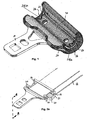
- Figur 1FIG. 1
- Eine dreidimensionale Darstellung einer Gurtzunge,A three-dimensional representation of a belt tongue,
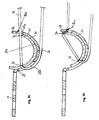
- Figur 2aFIG. 2a
-
die Gurtzunge aus
Figur 1 ohne Kunststoffumhüllung und mit aufgeschnittenen Stirnseiten mit eingelegtem Gurtband im nicht blockierten Zustand,the belt tongue outFIG. 1 without plastic coating and with cut-open ends with inlaid webbing in unblocked condition, - Figur 2bFIG. 2b
-
einen Schnitt durch die
Figur 2a entlang der Schnittlinie A-A,a cut through theFIG. 2a along the section line AA, - Figur 3aFIG. 3a
-
das in
Figur 2a Gezeigte im blockierten Zustand undthis inFIG. 2a Shown in the blocked state and - Figur 3bFIG. 3b
-
einen Schnitt entlang der Ebene A-A aus
Figur 3a .a section along the plane AAFIG. 3a ,
Die
Der Zungengrundkörper 20 weist zwei Seitenarme 26 auf, welche, wie man beispielsweise mit Blick auf
Auf der inneren Oberfläche 20a des Zungengrundkörpers 20, welche als Gleitfläche dient, ist das Umlenk- und Klemmelement 30 angeordnet. Es ist ebenfalls rinnenförmig ausgebildet und der Radius seiner konvexen Außenfläche entspricht dem Radius der inneren Oberfläche 20a des Zungengrundkörpers 20. Dies ist insbesondere gut in den
Im in
Bei Überschreiten einer definierten Grenzkraft, welche das Gurtband G auf die Umlenkkante 32 ausübt (diese liegt in der Regel in einer Größenordnung zwischen 10 und 20 kN), brechen die Abbrechnasen 28 und das Gurtband G drückt das Umlenk- und Klemmelement 30 in die in den
Man sieht, dass konstruktionsbedingt das Umlenk- und Klemmelement 30 sehr leicht ausgebildet sein kann und nur ein geringer Bewegungsweg erforderlich ist, wodurch die gewünschten kurzen Reaktionszeiten erreicht werden. Ein weiterer Vorteil ist die einfache Herstellbarkeit der Gurtzunge, insbesondere ist es möglich, das Umlenk- und Klemmelement 30 in den Metallkern 21 einzulegen und diese Anordnung dann zu umspritzen, wobei auch die Abbrech-Nasen erzeugt werden. Alternativ hierzu kann auch zunächst der Metallkern umspritzt und dann das Umlenk- und Klemmelement eingelegt werden. Die Abbrech-Nasen werden dann durch kurzes Erwärmen der entsprechenden Bereiche der Führungsstege erzeugt, wobei eine gewisse Materialmenge aufgeschmolzen wird und in die jeweilige Ausnehmung läuft. Bei Verfahren können insbesondere mit einem hohem Automatisierungsgrad durchgeführt werden.It can be seen that, by design, the deflecting and clamping
- 1010
- Verbindungsplatteconnecting plate
- 2020
- ZungengrundkörperTongue main body
- 2121
- Metallkernmetal core
- 2222
- oberer Stegupper jetty
- 22a22a
- Klemmbackenjaws
- 2323
- unterer Steglower jetty
- 2424
- Stützstegsupporting web
- 25a25a
- obere Öseupper eyelet
- 25b25b
- untere Öselower eyelet
- 2626
- Seitenarmsidearm
- 2727
- Führungsstegguide web
- 2828
- Abbrech-NaseBreak-nose
- 3030
- Umlenk- und KlemmelementDeflection and clamping element
- 3232
- Umlenkkantedeflecting
- 3434
- Klemmkanteclamping edge
- 3636
- Ausnehmungrecess
- 3838
- Führungsschenkelguide leg
- GG
- Gurtbelt
Claims (8)
- Belt latch for a safety belt comprising a connection plate (10) for connecting the belt latch to a buckle, a latch main body (20) being rigidly connected to the connecting plate (10), and a bending and clamping element (30) with a bending edge (32), said bending and clamping element being arranged on the latch main body (20) in a way that it rotates around a rotation axis in relation to the latch main body, if the force in the belt exceeds a defined force, whereby said bending and clamping elements comprises a convex outer surface,
characterised in that the bending and clamping element (30) is mounted to the latch main body (20) via its outer surface. - Belt latch according to claim 1, characterised in that the bending and clamping element has the shape of a half pipe so that the rotation axis lies outside the bending and clamping element.
- Belt latch according to one of the preceding claims, characterised in that the latch main body comprises two side arms (26).
- Belt latch according to claim 3, characterised in that each side arm shows a guiding stud (27) positioning the bending and clamping element.
- Belt latch according to one of the claims 3 or 4, characterised in that a reinforcing stud (24) extends between the side arms, whereby the bending and clamping element is in contact to the reinforcing stud at least in the rotated state.
- Belt latch according to one of the preceding claims, characterised in that at least one breaking fixation is provided which arrests the bending and clamping element at the latch main body in the force-free state.
- Belt latch according to claim 3 or 4 and claim 6, characterised in that the breaking fixation is allocated to the area of the side arms.
- Belt latch according to claim 7, characterised in that the breaking fixation comprises breaking noses (28) at the side arms engaging axially into recesses (36) of the bending and clamping element.
Applications Claiming Priority (2)
| Application Number | Priority Date | Filing Date | Title |
|---|---|---|---|
| DE102006005886A DE102006005886B4 (en) | 2006-02-09 | 2006-02-09 | Belt tongue for a safety belt |
| PCT/EP2007/000843 WO2007090551A1 (en) | 2006-02-09 | 2007-02-01 | Belt latch for a safety belt |
Publications (2)
| Publication Number | Publication Date |
|---|---|
| EP1983857A1 EP1983857A1 (en) | 2008-10-29 |
| EP1983857B1 true EP1983857B1 (en) | 2009-07-29 |
Family
ID=37919932
Family Applications (1)
| Application Number | Title | Priority Date | Filing Date |
|---|---|---|---|
| EP07703179A Active EP1983857B1 (en) | 2006-02-09 | 2007-02-01 | Belt latch for a safety belt |
Country Status (8)
| Country | Link |
|---|---|
| US (1) | US7712194B2 (en) |
| EP (1) | EP1983857B1 (en) |
| JP (1) | JP5020977B2 (en) |
| CN (1) | CN101378673B (en) |
| AT (1) | ATE437584T1 (en) |
| DE (2) | DE102006005886B4 (en) |
| ES (1) | ES2331032T3 (en) |
| WO (1) | WO2007090551A1 (en) |
Cited By (4)
| Publication number | Priority date | Publication date | Assignee | Title |
|---|---|---|---|---|
| DE102009040118A1 (en) | 2009-09-04 | 2011-03-10 | Autoliv Development Ab | Passenger front airbag and motor vehicle |
| WO2017174650A1 (en) | 2016-04-08 | 2017-10-12 | Autoliv Development Ab | Buckle tongue with a deflecting element |
| US11142161B2 (en) | 2016-03-25 | 2021-10-12 | Joyson Safety Systems Germany Gmbh | Belt deflector |
| US11547183B2 (en) | 2018-11-29 | 2023-01-10 | Joyson Safety Systems Germany Gmbh | Belt deflector |
Families Citing this family (26)
| Publication number | Priority date | Publication date | Assignee | Title |
|---|---|---|---|---|
| JP5208133B2 (en) | 2007-02-12 | 2013-06-12 | タカタ・ペトリ アーゲー | Buckle device |
| DE102008037963A1 (en) * | 2008-08-13 | 2010-02-18 | Takata-Petri Ag | buckle device |
| DE102009015202B3 (en) * | 2009-03-31 | 2010-04-29 | Autoliv Development Ab | Belt tongue for three-point-safety belt, is provided with tongue base body, C- shaped deflecting and clamping element with contact surface for three-point-safety belt |
| EP2377417B1 (en) * | 2010-04-15 | 2013-01-02 | Volvo Car Corporation | Belt latch for a safety belt |
| DE102010034040B4 (en) | 2010-08-11 | 2012-06-28 | Autoliv Development Ab | Seat belt device for a motor vehicle |
| DE202010013986U1 (en) * | 2010-09-20 | 2012-01-10 | Trw Vehicle Safety Systems Inc. | Locking tongue for a safety belt |
| US8474106B2 (en) | 2011-02-04 | 2013-07-02 | GM Global Technology Operations LLC | Seat belt latch plate assembly |
| US8820788B2 (en) * | 2011-05-09 | 2014-09-02 | Tk Holdings Inc. | Occupant restraint system |
| JP5810010B2 (en) * | 2011-05-20 | 2015-11-11 | タカタ株式会社 | Tongue and seat belt device using the same |
| JP2013060114A (en) | 2011-09-13 | 2013-04-04 | Tokai Rika Co Ltd | Tongue for seat belt device and the seat belt device |
| US8813316B2 (en) * | 2011-10-25 | 2014-08-26 | GM Global Technology Operations LLC | Seat belt latch plate assembly |
| DE102012020919B4 (en) | 2012-10-25 | 2018-02-15 | Autoliv Development Ab | Buckle tongue device for a safety belt |
| EP2969662B1 (en) | 2013-03-15 | 2018-11-07 | Trw Vehicle Safety Systems, Inc. | A seat belt system |
| WO2015025801A1 (en) | 2013-08-20 | 2015-02-26 | オートリブ ディベロップメント エービー | Locking tongue |
| EP2901882B1 (en) | 2014-01-30 | 2017-05-03 | Autoliv Development AB | Lockable belt latch for a three-point safety belt |
| DE102014106097B4 (en) * | 2014-04-30 | 2019-08-29 | Autoliv Development Ab | Lock tongue with sliding in the insertion direction clamping element |
| DE102014007125A1 (en) * | 2014-05-16 | 2015-11-19 | Trw Automotive Gmbh | Insertion tongue and method for producing a tongue |
| DE102014210094B4 (en) | 2014-05-27 | 2019-11-28 | Autoliv Development Ab | Belt tongue for a three-point safety belt |
| CN104082911A (en) * | 2014-07-12 | 2014-10-08 | 汤荣民 | Novel automobile safety belt lock catch and heat treatment technology thereof |
| DE102014114207B4 (en) * | 2014-09-30 | 2016-11-17 | Autoliv Development Ab | Lock tongue with a guide portion having a clamping element |
| CN104323540A (en) * | 2014-11-03 | 2015-02-04 | 宁波市镇海西门专利技术开发有限公司 | Safety belt buckle retaining door |
| JP2018184134A (en) * | 2017-04-27 | 2018-11-22 | Joyson Safety Systems Japan株式会社 | Tongue and seat belt device |
| DE102017210260B4 (en) | 2017-06-20 | 2021-02-18 | Autoliv Development Ab | Release device for releasing belt slack from a fixed belt loop into a section of a seat belt of a seat belt device and a seat belt device with such a release device |
| CN107380117B (en) * | 2017-07-22 | 2019-07-09 | 海南飞宇实业有限公司 | Automobile self-rescue safety belt |
| US10543806B2 (en) * | 2018-02-27 | 2020-01-28 | Ford Global Technologies, Llc | Seatbelt assembly |
| CN110450753A (en) * | 2019-09-18 | 2019-11-15 | 延锋汽车智能安全系统有限责任公司 | The self-locking lock tongue of safety belt |
Family Cites Families (7)
| Publication number | Priority date | Publication date | Assignee | Title |
|---|---|---|---|---|
| US4876770A (en) * | 1988-10-03 | 1989-10-31 | Indiana Mills & Manufacturing, Inc. | Anti-creep cam bar |
| US5100176A (en) * | 1991-05-10 | 1992-03-31 | Trw Vehicle Safety Systems Inc. | Tongue assembly |
| US5879816A (en) | 1995-11-30 | 1999-03-09 | Nihon Parkerizing Co., Ltd. | Metallic sliding material |
| US5806148A (en) * | 1997-05-19 | 1998-09-15 | Trw Vehicle Safety Systems Inc. | Tongue assembly |
| US5870816A (en) * | 1997-05-19 | 1999-02-16 | Trw Vehicle Safety Systems Inc. | Method of assembling a tongue assembly for use with a seat belt system |
| JP3544322B2 (en) * | 1999-07-01 | 2004-07-21 | ダイハツ工業株式会社 | Tongue plate for seat belt device |
| DE102004023394B4 (en) * | 2004-05-12 | 2006-11-02 | Daimlerchrysler Ag | Locking tongue for a safety belt system |
-
2006
- 2006-02-09 DE DE102006005886A patent/DE102006005886B4/en active Active
-
2007
- 2007-02-01 JP JP2008553656A patent/JP5020977B2/en active Active
- 2007-02-01 CN CN2007800050102A patent/CN101378673B/en active Active
- 2007-02-01 EP EP07703179A patent/EP1983857B1/en active Active
- 2007-02-01 ES ES07703179T patent/ES2331032T3/en active Active
- 2007-02-01 DE DE502007001185T patent/DE502007001185D1/en active Active
- 2007-02-01 US US12/278,496 patent/US7712194B2/en active Active
- 2007-02-01 WO PCT/EP2007/000843 patent/WO2007090551A1/en active Application Filing
- 2007-02-01 AT AT07703179T patent/ATE437584T1/en active
Cited By (8)
| Publication number | Priority date | Publication date | Assignee | Title |
|---|---|---|---|---|
| DE102009040118A1 (en) | 2009-09-04 | 2011-03-10 | Autoliv Development Ab | Passenger front airbag and motor vehicle |
| WO2011026617A1 (en) | 2009-09-04 | 2011-03-10 | Autoliv Development Ab | Passenger front airbag |
| US8544882B2 (en) | 2009-09-04 | 2013-10-01 | Autoliv Development Ab | Passenger front airbag |
| US11142161B2 (en) | 2016-03-25 | 2021-10-12 | Joyson Safety Systems Germany Gmbh | Belt deflector |
| WO2017174650A1 (en) | 2016-04-08 | 2017-10-12 | Autoliv Development Ab | Buckle tongue with a deflecting element |
| DE102016106440A1 (en) | 2016-04-08 | 2017-10-12 | Autoliv Development Ab | Locking tongue with deflection element |
| US10843657B2 (en) | 2016-04-08 | 2020-11-24 | Autoliv Development Ab | Seat belt buckle tongue with a deflecting element |
| US11547183B2 (en) | 2018-11-29 | 2023-01-10 | Joyson Safety Systems Germany Gmbh | Belt deflector |
Also Published As
| Publication number | Publication date |
|---|---|
| US7712194B2 (en) | 2010-05-11 |
| JP2009525909A (en) | 2009-07-16 |
| US20090025193A1 (en) | 2009-01-29 |
| EP1983857A1 (en) | 2008-10-29 |
| JP5020977B2 (en) | 2012-09-05 |
| CN101378673A (en) | 2009-03-04 |
| ES2331032T3 (en) | 2009-12-18 |
| DE502007001185D1 (en) | 2009-09-10 |
| CN101378673B (en) | 2011-07-27 |
| ATE437584T1 (en) | 2009-08-15 |
| DE102006005886A1 (en) | 2007-08-23 |
| WO2007090551A1 (en) | 2007-08-16 |
| DE102006005886B4 (en) | 2007-11-08 |
Similar Documents
| Publication | Publication Date | Title |
|---|---|---|
| EP1983857B1 (en) | Belt latch for a safety belt | |
| EP3439925B1 (en) | Belt tongue comprising a clamping element that has a guide section | |
| EP3642084B1 (en) | Safety belt device for a vehicle | |
| EP3529503B1 (en) | Fixing element for securing a retaining element on a support and system comprising a fixing element and a retaining element | |
| DE10304574A1 (en) | Locking device for a vehicle seat | |
| DE102008045999A1 (en) | Motor vehicle seat with a backrest and a belt deflection | |
| DE102008034958B3 (en) | buckle | |
| EP3762252A1 (en) | Longitudinal adjustment device for a vehicle seat, having a floor rail, a longitudinally slidable seat rail and a locking unit | |
| DE2812824A1 (en) | ANCHORING FOR A BELT SYSTEM IN VEHICLES | |
| EP2683577B1 (en) | Unlocking device | |
| DE102015012411B4 (en) | headrest | |
| DE10133707B4 (en) | External hinge for a backrest holder | |
| EP3313712B1 (en) | Axial ball joint articulation | |
| DE10135627B4 (en) | Locking device for a vehicle seat | |
| EP1668262A1 (en) | Ball socket | |
| EP3819513B1 (en) | Sliding bearing, equipment device with at least one sliding bearing and feature with at least one rotatable mounted bearing | |
| DE102011012461B4 (en) | Vehicle seat and use of a webbing attachment | |
| EP1334012B1 (en) | Deflection fitting for the safety belt of a motor vehicle | |
| EP1134129B1 (en) | Device for holding the roll bar of a roll bar protection system | |
| DE19904620B4 (en) | Snap-in device with reset function for a turn signal switch | |
| DE3126066A1 (en) | Snap hook | |
| DE10052920C1 (en) | Fixing end plate for automobile seatbelt formed from flat metal stamping bent through 180 degrees to provide double layer | |
| DE10357812B4 (en) | Belt reel for a seat belt retractor | |
| DE3314588C2 (en) | ||
| DE102009052774B4 (en) | Device for locking two components pivotable about a common joint |
Legal Events
| Date | Code | Title | Description |
|---|---|---|---|
| PUAI | Public reference made under article 153(3) epc to a published international application that has entered the european phase |
Free format text: ORIGINAL CODE: 0009012 |
|
| 17P | Request for examination filed |
Effective date: 20080909 |
|
| AK | Designated contracting states |
Kind code of ref document: A1 Designated state(s): AT BE BG CH CY CZ DE DK EE ES FI FR GB GR HU IE IS IT LI LT LU LV MC NL PL PT RO SE SI SK TR |
|
| GRAP | Despatch of communication of intention to grant a patent |
Free format text: ORIGINAL CODE: EPIDOSNIGR1 |
|
| GRAS | Grant fee paid |
Free format text: ORIGINAL CODE: EPIDOSNIGR3 |
|
| GRAA | (expected) grant |
Free format text: ORIGINAL CODE: 0009210 |
|
| AK | Designated contracting states |
Kind code of ref document: B1 Designated state(s): AT BE BG CH CY CZ DE DK EE ES FI FR GB GR HU IE IS IT LI LT LU LV MC NL PL PT RO SE SI SK TR |
|
| REG | Reference to a national code |
Ref country code: GB Ref legal event code: FG4D Free format text: NOT ENGLISH |
|
| REG | Reference to a national code |
Ref country code: CH Ref legal event code: EP |
|
| REG | Reference to a national code |
Ref country code: IE Ref legal event code: FG4D |
|
| REF | Corresponds to: |
Ref document number: 502007001185 Country of ref document: DE Date of ref document: 20090910 Kind code of ref document: P |
|
| REG | Reference to a national code |
Ref country code: SE Ref legal event code: TRGR |
|
| REG | Reference to a national code |
Ref country code: ES Ref legal event code: FG2A Ref document number: 2331032 Country of ref document: ES Kind code of ref document: T3 |
|
| NLV1 | Nl: lapsed or annulled due to failure to fulfill the requirements of art. 29p and 29m of the patents act | ||
| PG25 | Lapsed in a contracting state [announced via postgrant information from national office to epo] |
Ref country code: LT Free format text: LAPSE BECAUSE OF FAILURE TO SUBMIT A TRANSLATION OF THE DESCRIPTION OR TO PAY THE FEE WITHIN THE PRESCRIBED TIME-LIMIT Effective date: 20090729 Ref country code: IS Free format text: LAPSE BECAUSE OF FAILURE TO SUBMIT A TRANSLATION OF THE DESCRIPTION OR TO PAY THE FEE WITHIN THE PRESCRIBED TIME-LIMIT Effective date: 20091129 Ref country code: FI Free format text: LAPSE BECAUSE OF FAILURE TO SUBMIT A TRANSLATION OF THE DESCRIPTION OR TO PAY THE FEE WITHIN THE PRESCRIBED TIME-LIMIT Effective date: 20090729 |
|
| PG25 | Lapsed in a contracting state [announced via postgrant information from national office to epo] |
Ref country code: LV Free format text: LAPSE BECAUSE OF FAILURE TO SUBMIT A TRANSLATION OF THE DESCRIPTION OR TO PAY THE FEE WITHIN THE PRESCRIBED TIME-LIMIT Effective date: 20090729 Ref country code: PL Free format text: LAPSE BECAUSE OF FAILURE TO SUBMIT A TRANSLATION OF THE DESCRIPTION OR TO PAY THE FEE WITHIN THE PRESCRIBED TIME-LIMIT Effective date: 20090729 Ref country code: SI Free format text: LAPSE BECAUSE OF FAILURE TO SUBMIT A TRANSLATION OF THE DESCRIPTION OR TO PAY THE FEE WITHIN THE PRESCRIBED TIME-LIMIT Effective date: 20090729 Ref country code: NL Free format text: LAPSE BECAUSE OF FAILURE TO SUBMIT A TRANSLATION OF THE DESCRIPTION OR TO PAY THE FEE WITHIN THE PRESCRIBED TIME-LIMIT Effective date: 20090729 |
|
| REG | Reference to a national code |
Ref country code: IE Ref legal event code: FD4D |
|
| PG25 | Lapsed in a contracting state [announced via postgrant information from national office to epo] |
Ref country code: PT Free format text: LAPSE BECAUSE OF FAILURE TO SUBMIT A TRANSLATION OF THE DESCRIPTION OR TO PAY THE FEE WITHIN THE PRESCRIBED TIME-LIMIT Effective date: 20091129 Ref country code: BG Free format text: LAPSE BECAUSE OF FAILURE TO SUBMIT A TRANSLATION OF THE DESCRIPTION OR TO PAY THE FEE WITHIN THE PRESCRIBED TIME-LIMIT Effective date: 20091029 |
|
| PG25 | Lapsed in a contracting state [announced via postgrant information from national office to epo] |
Ref country code: EE Free format text: LAPSE BECAUSE OF FAILURE TO SUBMIT A TRANSLATION OF THE DESCRIPTION OR TO PAY THE FEE WITHIN THE PRESCRIBED TIME-LIMIT Effective date: 20090729 Ref country code: CZ Free format text: LAPSE BECAUSE OF FAILURE TO SUBMIT A TRANSLATION OF THE DESCRIPTION OR TO PAY THE FEE WITHIN THE PRESCRIBED TIME-LIMIT Effective date: 20090729 Ref country code: DK Free format text: LAPSE BECAUSE OF FAILURE TO SUBMIT A TRANSLATION OF THE DESCRIPTION OR TO PAY THE FEE WITHIN THE PRESCRIBED TIME-LIMIT Effective date: 20090729 Ref country code: RO Free format text: LAPSE BECAUSE OF FAILURE TO SUBMIT A TRANSLATION OF THE DESCRIPTION OR TO PAY THE FEE WITHIN THE PRESCRIBED TIME-LIMIT Effective date: 20090729 Ref country code: IE Free format text: LAPSE BECAUSE OF FAILURE TO SUBMIT A TRANSLATION OF THE DESCRIPTION OR TO PAY THE FEE WITHIN THE PRESCRIBED TIME-LIMIT Effective date: 20090729 |
|
| PG25 | Lapsed in a contracting state [announced via postgrant information from national office to epo] |
Ref country code: SK Free format text: LAPSE BECAUSE OF FAILURE TO SUBMIT A TRANSLATION OF THE DESCRIPTION OR TO PAY THE FEE WITHIN THE PRESCRIBED TIME-LIMIT Effective date: 20090729 |
|
| PLBE | No opposition filed within time limit |
Free format text: ORIGINAL CODE: 0009261 |
|
| STAA | Information on the status of an ep patent application or granted ep patent |
Free format text: STATUS: NO OPPOSITION FILED WITHIN TIME LIMIT |
|
| 26N | No opposition filed |
Effective date: 20100503 |
|
| BERE | Be: lapsed |
Owner name: AUTOLIV DEVELOPMENT A.B. Effective date: 20100228 |
|
| PG25 | Lapsed in a contracting state [announced via postgrant information from national office to epo] |
Ref country code: GR Free format text: LAPSE BECAUSE OF FAILURE TO SUBMIT A TRANSLATION OF THE DESCRIPTION OR TO PAY THE FEE WITHIN THE PRESCRIBED TIME-LIMIT Effective date: 20091030 Ref country code: MC Free format text: LAPSE BECAUSE OF NON-PAYMENT OF DUE FEES Effective date: 20100301 |
|
| PG25 | Lapsed in a contracting state [announced via postgrant information from national office to epo] |
Ref country code: BE Free format text: LAPSE BECAUSE OF NON-PAYMENT OF DUE FEES Effective date: 20100228 |
|
| PGRI | Patent reinstated in contracting state [announced from national office to epo] |
Ref country code: IT Effective date: 20110501 |
|
| PGRI | Patent reinstated in contracting state [announced from national office to epo] |
Ref country code: IT Effective date: 20110501 |
|
| REG | Reference to a national code |
Ref country code: CH Ref legal event code: PL |
|
| GBPC | Gb: european patent ceased through non-payment of renewal fee |
Effective date: 20110201 |
|
| PG25 | Lapsed in a contracting state [announced via postgrant information from national office to epo] |
Ref country code: LI Free format text: LAPSE BECAUSE OF NON-PAYMENT OF DUE FEES Effective date: 20110228 Ref country code: CH Free format text: LAPSE BECAUSE OF NON-PAYMENT OF DUE FEES Effective date: 20110228 |
|
| PG25 | Lapsed in a contracting state [announced via postgrant information from national office to epo] |
Ref country code: GB Free format text: LAPSE BECAUSE OF NON-PAYMENT OF DUE FEES Effective date: 20110201 |
|
| PG25 | Lapsed in a contracting state [announced via postgrant information from national office to epo] |
Ref country code: CY Free format text: LAPSE BECAUSE OF FAILURE TO SUBMIT A TRANSLATION OF THE DESCRIPTION OR TO PAY THE FEE WITHIN THE PRESCRIBED TIME-LIMIT Effective date: 20090729 |
|
| PG25 | Lapsed in a contracting state [announced via postgrant information from national office to epo] |
Ref country code: LU Free format text: LAPSE BECAUSE OF NON-PAYMENT OF DUE FEES Effective date: 20100201 Ref country code: HU Free format text: LAPSE BECAUSE OF FAILURE TO SUBMIT A TRANSLATION OF THE DESCRIPTION OR TO PAY THE FEE WITHIN THE PRESCRIBED TIME-LIMIT Effective date: 20100130 |
|
| PG25 | Lapsed in a contracting state [announced via postgrant information from national office to epo] |
Ref country code: TR Free format text: LAPSE BECAUSE OF FAILURE TO SUBMIT A TRANSLATION OF THE DESCRIPTION OR TO PAY THE FEE WITHIN THE PRESCRIBED TIME-LIMIT Effective date: 20090729 |
|
| REG | Reference to a national code |
Ref country code: AT Ref legal event code: MM01 Ref document number: 437584 Country of ref document: AT Kind code of ref document: T Effective date: 20120201 |
|
| PG25 | Lapsed in a contracting state [announced via postgrant information from national office to epo] |
Ref country code: AT Free format text: LAPSE BECAUSE OF NON-PAYMENT OF DUE FEES Effective date: 20120201 |
|
| REG | Reference to a national code |
Ref country code: FR Ref legal event code: PLFP Year of fee payment: 10 |
|
| REG | Reference to a national code |
Ref country code: FR Ref legal event code: PLFP Year of fee payment: 11 |
|
| REG | Reference to a national code |
Ref country code: FR Ref legal event code: PLFP Year of fee payment: 12 |
|
| REG | Reference to a national code |
Ref country code: DE Ref legal event code: R082 Ref document number: 502007001185 Country of ref document: DE Representative=s name: SCHOEN, THILO, DIPL.-PHYS., DE |
|
| PGFP | Annual fee paid to national office [announced via postgrant information from national office to epo] |
Ref country code: FR Payment date: 20230217 Year of fee payment: 17 Ref country code: ES Payment date: 20230317 Year of fee payment: 17 |
|
| PGFP | Annual fee paid to national office [announced via postgrant information from national office to epo] |
Ref country code: SE Payment date: 20230220 Year of fee payment: 17 Ref country code: IT Payment date: 20230228 Year of fee payment: 17 |
|
| PGFP | Annual fee paid to national office [announced via postgrant information from national office to epo] |
Ref country code: ES Payment date: 20240307 Year of fee payment: 18 |
|
| PGFP | Annual fee paid to national office [announced via postgrant information from national office to epo] |
Ref country code: DE Payment date: 20240228 Year of fee payment: 18 |