EP1983228A1 - Method for optimising control of the synchronisers in a gearbox when shifting gears - Google Patents
Method for optimising control of the synchronisers in a gearbox when shifting gears Download PDFInfo
- Publication number
- EP1983228A1 EP1983228A1 EP08305097A EP08305097A EP1983228A1 EP 1983228 A1 EP1983228 A1 EP 1983228A1 EP 08305097 A EP08305097 A EP 08305097A EP 08305097 A EP08305097 A EP 08305097A EP 1983228 A1 EP1983228 A1 EP 1983228A1
- Authority
- EP
- European Patent Office
- Prior art keywords
- ratio
- final
- synchronizer
- synchronization
- speed
- Prior art date
- Legal status (The legal status is an assumption and is not a legal conclusion. Google has not performed a legal analysis and makes no representation as to the accuracy of the status listed.)
- Withdrawn
Links
Images


Classifications
-
- F—MECHANICAL ENGINEERING; LIGHTING; HEATING; WEAPONS; BLASTING
- F16—ENGINEERING ELEMENTS AND UNITS; GENERAL MEASURES FOR PRODUCING AND MAINTAINING EFFECTIVE FUNCTIONING OF MACHINES OR INSTALLATIONS; THERMAL INSULATION IN GENERAL
- F16H—GEARING
- F16H61/00—Control functions within control units of change-speed- or reversing-gearings for conveying rotary motion ; Control of exclusively fluid gearing, friction gearing, gearings with endless flexible members or other particular types of gearing
- F16H61/04—Smoothing ratio shift
- F16H61/0403—Synchronisation before shifting
-
- F—MECHANICAL ENGINEERING; LIGHTING; HEATING; WEAPONS; BLASTING
- F16—ENGINEERING ELEMENTS AND UNITS; GENERAL MEASURES FOR PRODUCING AND MAINTAINING EFFECTIVE FUNCTIONING OF MACHINES OR INSTALLATIONS; THERMAL INSULATION IN GENERAL
- F16H—GEARING
- F16H61/00—Control functions within control units of change-speed- or reversing-gearings for conveying rotary motion ; Control of exclusively fluid gearing, friction gearing, gearings with endless flexible members or other particular types of gearing
- F16H61/26—Generation or transmission of movements for final actuating mechanisms
- F16H61/28—Generation or transmission of movements for final actuating mechanisms with at least one movement of the final actuating mechanism being caused by a non-mechanical force, e.g. power-assisted
- F16H61/2807—Generation or transmission of movements for final actuating mechanisms with at least one movement of the final actuating mechanism being caused by a non-mechanical force, e.g. power-assisted using electric control signals for shift actuators, e.g. electro-hydraulic control therefor
-
- F—MECHANICAL ENGINEERING; LIGHTING; HEATING; WEAPONS; BLASTING
- F16—ENGINEERING ELEMENTS AND UNITS; GENERAL MEASURES FOR PRODUCING AND MAINTAINING EFFECTIVE FUNCTIONING OF MACHINES OR INSTALLATIONS; THERMAL INSULATION IN GENERAL
- F16H—GEARING
- F16H61/00—Control functions within control units of change-speed- or reversing-gearings for conveying rotary motion ; Control of exclusively fluid gearing, friction gearing, gearings with endless flexible members or other particular types of gearing
- F16H61/26—Generation or transmission of movements for final actuating mechanisms
- F16H61/28—Generation or transmission of movements for final actuating mechanisms with at least one movement of the final actuating mechanism being caused by a non-mechanical force, e.g. power-assisted
- F16H2061/2823—Controlling actuator force way characteristic, i.e. controlling force or movement depending on the actuator position, e.g. for adapting force to synchronisation and engagement of gear clutch
-
- F—MECHANICAL ENGINEERING; LIGHTING; HEATING; WEAPONS; BLASTING
- F16—ENGINEERING ELEMENTS AND UNITS; GENERAL MEASURES FOR PRODUCING AND MAINTAINING EFFECTIVE FUNCTIONING OF MACHINES OR INSTALLATIONS; THERMAL INSULATION IN GENERAL
- F16H—GEARING
- F16H2342/00—Calibrating
- F16H2342/04—Calibrating engagement of friction elements
- F16H2342/044—Torque transmitting capability
-
- F—MECHANICAL ENGINEERING; LIGHTING; HEATING; WEAPONS; BLASTING
- F16—ENGINEERING ELEMENTS AND UNITS; GENERAL MEASURES FOR PRODUCING AND MAINTAINING EFFECTIVE FUNCTIONING OF MACHINES OR INSTALLATIONS; THERMAL INSULATION IN GENERAL
- F16H—GEARING
- F16H59/00—Control inputs to control units of change-speed-, or reversing-gearings for conveying rotary motion
- F16H59/36—Inputs being a function of speed
- F16H59/46—Inputs being a function of speed dependent on a comparison between speeds
Definitions
- the invention relates to a method for optimizing control of the synchronizers of a gearbox during a gearshift.
- the purpose of the invention is notably to limit the synchronization time during the change of gear ratio.
- the invention finds a particularly advantageous application with gearboxes comprising actuators ensuring the displacement of the jaw of the gearbox.
- Known vehicles comprise a traction chain formed by a propulsion device (formed by a heat engine and / or an electric machine), a clutch, and a gearbox which drives the wheels of the vehicle.
- the clutch is connected on the one hand to the propulsion device and on the other hand to the gearbox, itself connected to the wheels.
- the gearbox comprises a primary shaft connected to the clutch and a secondary shaft connected to the wheels of the vehicle, these two shafts being connected to each other by means of gears forming the gear ratios.
- Each gear has a wheel connected to one of the shafts and a idler gear mounted on the other shaft. Dogs each provided with a synchronizer are used to selectively link the idle gears to the shaft on which they are mounted to ensure a gear shift.
- the dog is rotatably connected to its shaft but is movable axially to allow attachment with a pinion. It is called dog clutch when the dog enters into cooperation with the idler gear so that a gear ratio is engaged, and declutching when the dog disengages from the idler gear so that the ratio is disengaged.
- the synchronizers mounted on the claws have the role of causing the clutch and the idler gear to mesh at identical rotational speeds before realizing the clutch. Indeed, during a gearshift, the dog is linked to the secondary shaft which is connected to the wheels, while the idler gear ratio to engage is connected to the primary shaft (or vice versa). But the primary shaft and the secondary shaft turn to different speeds. The synchronizer then synchronizes the speed of the primary shaft with that of the secondary shaft connected to the wheels.
- the control of the gearbox gearbox changes uses tables according to the vehicle conditions and the will of the driver. The more the passage is determined to be "sporty", the shorter the synchronization time.
- the document FR-A-2799256 describes the possibility of selecting the synchronization time interval according to the nature of the gearshift (up or down) and the driving mode (sporty or economical).
- the main characteristic of a synchronizer is that the synchronization time decreases as the force applied to this synchronizer increases.
- the rate of rise in force is a criterion for reducing the synchronization time at maximum applied iso-stress. In order to reduce the synchronization time, it is therefore necessary to increase the speed of rise in effort and the maximum effort of synchronization.
- one of the limitations of the synchronization system lies in the power dissipated by the synchronizer without risk of deterioration of its components.
- the invention proposes to take these parameters into account in order to reduce the speed ratio change time.
- the invention consists of a strategy for controlling synchronizers with, as input criterion, the maximum power allowed by the synchronizer. This power depends on the synchronizer materials and the friction surface between the idle gear and the synchronizer.
- the invention thus consists in the optimal use of the power handling characteristics of the synchronizers.
- the invention makes it possible to guarantee an optimized synchronization time, as short as possible, whatever the type of passage, without causing damage to the mechanism of the synchronizer.
- vehicle conditions such as the shaft speed are memorized. the wheel speed, and calculating the difference in speed between the initial report and the final report.
- a ramp of effort increase as well as a maximum force are applied to the passage actuator in order to apply a synchronization torque which makes it possible to optimize the synchronization time while respecting the maximum power allowed by the synchronizer.
- the synchronous torque has a ramp up effort to a maximum torque synchronization, the maximum torque being applied until the final gear ratio is reached by the primary shaft .
- the ramp mounted in force as a function of time is a fixed value which depends on the capacity of the actuator of the synchronizer.
- Wdiff being the ratio difference between the initial ratio (RI) and the final ratio (RF)
- Jap being the inertia of the rotating parts subjected to the synchronization torque, Jap being calculated according to the final report to be synchronized, a is the synchronization torque per unit of effort that depends on the geometric characteristics of the synchronizer.
- the maximum power allowed by the synchronizer and the synchronous torque per unit of effort are stored in the computer of the gearbox.
- the gear change is controlled by the driver and / or by the automatic gearshift mode.
- the figure 1 shows a vehicle 1 comprising a traction chain formed by a thermal engine 2, a clutch 3 connected on the one hand to the engine 2 thermal and on the other hand to a gearbox 4.
- This gearbox 4 is connected to the wheels 5 of the vehicle.
- the power train is completed by an electric machine 6 positioned on the input shaft of the gearbox 4 between the clutch 3 and the gearbox 4.
- the figure 2 shows a detailed view of the gearbox 4.
- the gearbox comprises a primary shaft 7 connected to the clutch 3 and a secondary shaft 8 connected to the wheels 5. These two shafts 7 and 8 are connected to one another by means of gears forming the gear ratios RI and RF (here only two gears are shown for ease of understanding).
- the initial ratio RI and the final report RF are each formed respectively by a wheel 11, 12 driven by the primary shaft 7 and an idle gear 13, 14 driven by the secondary shaft 8.
- a dog clutch 15 is mounted on the secondary shaft 8 between the two gears.
- the clutch 15 is rotatably connected to the shaft 8 and has a ring 17 movable axially.
- This ring 17 has teeth on the periphery of its radial face intended to cooperate with teeth 13.1, 14.1 of the idler gears 13, 14.
- the movable ring 17 moves towards the idler gear ratio to engage and meshes with him, so that the idler gear is connected in rotation to the shaft 8.
- the crown 17 mobile disengages the idler gear, so that this idler gear is no longer linked in rotation with the shaft 8.
- the clutch 15 is also provided with a synchronizer 18 which has the role of causing the clutch 15 and the pinion 13 or 14 to mesh at identical speeds of rotation before achieving the clutch.
- the gearbox 4 comprises an actuator 19 controlled by the computer 21 gearbox.
- the computer 21 also controls the opening and closing of the clutch 3.
- a first speed sensor 23 measuring the rotation speed of the primary shaft 7 and a second speed sensor 25 measuring the speed of rotation of the secondary shaft 8 are connected to the computer 21.
- the vehicle 1 also comprises a traction chain supervisor 29 which controls the thermal engine 2, the clutch 3 and the transmission computer 21.
- the ring 17 When the initial ratio RI is engaged at time t0, the ring 17 is clutched with the idler gear 14, while the pinion 13 is mounted loosely on the secondary shaft 8. As shown on the figure 4 , the primary shaft 7 then has a rotation speed WI.
- the sensor 23 measures, in a step 31, the speed of the primary shaft 7 and the sensor 25 measures, in a step 32, the speed of the secondary shaft 8.
- the IR report is disengaged.
- step 37 the difference Wdiff between the speed dog clutch 15 and the pinion gear 13 associated with the RF final report meshing.
- the value Wdiff is applied to the input of the block 39 for calculating the maximum target torque CsynMax to be applied to the synchronizer 18 to optimize the gearshift.
- the transmission computer 21 includes in its memory 38 the maximum permissible synchronization power Pmax for each synchronizer of the gearbox 4, as well as the torque "a" per unit of effort of each synchronizer (torque of generated synchronization for 1N of effort) which depend on the geometric characteristics of the synchronizers of the gearbox 4.
- the values Pmax and a relating to the synchronizer 18 of the final report RF are applied at the input of block 39.
- Jap being the known inertia a priori of the rotating parts subjected to the synchronization torque
- Jap being calculated according to the RF ratio to be synchronized
- b being the rise ramp in synchronization force according to the synchronizer 18 and the difference Wdiff.
- the ramps b rise in synchronization effort have values dependent on the architecture of the actuator and synchronizers. It is therefore possible to set a value depending on the capacity of the actuator, for example 14000 N / s.
- a step 40 the control of the synchronizer 18 is then parameterized, so that a setpoint torque Csyn having the shape of the curve represented in FIG. figure 4 is applied to the synchronizer 18.
- This torque has a ramp up effort up to torque CsynMax, CsynMax being applied until time t2 at which synchronization with the RF report is completed.
- a step 41 between t1 and t2, the actuator 19 is controlled so that the setpoint torque Csyn is applied to the synchronizer 18.
Landscapes
- Engineering & Computer Science (AREA)
- General Engineering & Computer Science (AREA)
- Mechanical Engineering (AREA)
- Control Of Transmission Device (AREA)
Abstract
Description
L'invention concerne un procédé d'optimisation de pilotage des synchroniseurs d'une boîte de vitesses lors d'un changement de rapport de vitesse. L'invention a notamment pour but de limiter le temps de synchronisation lors du changement de rapport de vitesse. L'invention trouve une application particulièrement avantageuse avec les boîtes de vitesses comportant des actionneurs assurant le déplacement des crabots de la boîte de vitesses.The invention relates to a method for optimizing control of the synchronizers of a gearbox during a gearshift. The purpose of the invention is notably to limit the synchronization time during the change of gear ratio. The invention finds a particularly advantageous application with gearboxes comprising actuators ensuring the displacement of the jaw of the gearbox.
Les véhicules connus comportent une chaîne de traction formée par un dispositif de propulsion (formé par un moteur thermique et/ou une machine électrique), un embrayage, et une boîte de vitesses qui entraîne les roues du véhicule. L'embrayage est relié d'une part au dispositif de propulsion et d'autre part à la boîte de vitesses, elle-même reliée aux roues.Known vehicles comprise a traction chain formed by a propulsion device (formed by a heat engine and / or an electric machine), a clutch, and a gearbox which drives the wheels of the vehicle. The clutch is connected on the one hand to the propulsion device and on the other hand to the gearbox, itself connected to the wheels.
Plus précisément, la boîte de vitesses comporte un arbre primaire relié à l'embrayage et un arbre secondaire relié aux roues du véhicule, ces deux arbres étant reliés entre eux par l'intermédiaire d'engrenages formant les rapports de vitesse.More specifically, the gearbox comprises a primary shaft connected to the clutch and a secondary shaft connected to the wheels of the vehicle, these two shafts being connected to each other by means of gears forming the gear ratios.
Chaque engrenage comporte une roue reliée sur un des arbres et un pignon fou monté sur l'autre arbre. Des crabots munis chacun d'un synchroniseur sont utilisés pour lier sélectivement les pignons fous à l'arbre sur lequel ils sont montés afin d'assurer un passage de vitesse.Each gear has a wheel connected to one of the shafts and a idler gear mounted on the other shaft. Dogs each provided with a synchronizer are used to selectively link the idle gears to the shaft on which they are mounted to ensure a gear shift.
A cet effet, le crabot est lié en rotation à son arbre mais est mobile axialement pour permettre un accrochage avec un pignon fou. On parle de crabotage lorsque le crabot entre en coopération avec le pignon fou de sorte qu'un rapport de vitesse est engagé, et de décrabotage lorsque le crabot se dégage du pignon fou de sorte que le rapport est désengagé.For this purpose, the dog is rotatably connected to its shaft but is movable axially to allow attachment with a pinion. It is called dog clutch when the dog enters into cooperation with the idler gear so that a gear ratio is engaged, and declutching when the dog disengages from the idler gear so that the ratio is disengaged.
Les synchroniseurs montés sur les crabots ont pour rôle d'amener le crabot et le pignon fou à engrener à des vitesses de rotation identiques avant de réaliser le crabotage. En effet, lors d'un changement de rapport de vitesse, le crabot est lié à l'arbre secondaire qui est relié aux roues, tandis que le pignon fou du rapport à engager est relié à l'arbre primaire (ou inversement). Or l'arbre primaire et l'arbre secondaire tournent à des vitesses différentes. Le synchroniseur permet alors de synchroniser le régime de l'arbre primaire avec celui de l'arbre secondaire relié aux roues.The synchronizers mounted on the claws have the role of causing the clutch and the idler gear to mesh at identical rotational speeds before realizing the clutch. Indeed, during a gearshift, the dog is linked to the secondary shaft which is connected to the wheels, while the idler gear ratio to engage is connected to the primary shaft (or vice versa). But the primary shaft and the secondary shaft turn to different speeds. The synchronizer then synchronizes the speed of the primary shaft with that of the secondary shaft connected to the wheels.
Le pilotage des changements de rapports de boîte de vitesses pilotées utilise des tables en fonction des conditions véhicules et de la volonté du conducteur. Plus le passage est déterminé comme devant être « sportif», plus le temps de synchronisation doit être court. Le document
La caractéristique principale d'un synchroniseur est que le temps de synchronisation diminue lorsque l'effort appliqué à ce synchroniseur augmente. En outre, la vitesse de montée en effort est un critère permettant de diminuer le temps de synchronisation à iso-effort maximal appliqué. Afin de réduire le temps de synchronisation, il faut donc augmenter la vitesse de montée en effort et l'effort maximal de synchronisation.The main characteristic of a synchronizer is that the synchronization time decreases as the force applied to this synchronizer increases. In addition, the rate of rise in force is a criterion for reducing the synchronization time at maximum applied iso-stress. In order to reduce the synchronization time, it is therefore necessary to increase the speed of rise in effort and the maximum effort of synchronization.
Toutefois, une des limites du système de synchronisation réside dans la puissance dissipée par le synchroniseur sans risque de détérioration de ses composants.However, one of the limitations of the synchronization system lies in the power dissipated by the synchronizer without risk of deterioration of its components.
L'invention se propose de tenir compte de ces paramètres pour diminuer le temps de changement de rapport de vitesse.The invention proposes to take these parameters into account in order to reduce the speed ratio change time.
A cet effet, l'invention consiste en une stratégie de pilotage des synchroniseurs avec comme critère d'entrée la puissance maximale admissible par le synchroniseur. Cette puissance dépend des matériaux du synchroniseur et de la surface de frottement entre le pignon fou et le synchroniseur. L'invention consiste ainsi en l'utilisation optimale des caractéristiques de tenue en puissance des synchroniseurs.For this purpose, the invention consists of a strategy for controlling synchronizers with, as input criterion, the maximum power allowed by the synchronizer. This power depends on the synchronizer materials and the friction surface between the idle gear and the synchronizer. The invention thus consists in the optimal use of the power handling characteristics of the synchronizers.
L'invention permet de garantir un temps de synchronisation optimisé, le plus court possible, quel que soit le type de passage, sans provoquer d'endommagement au mécanisme du synchroniseur.The invention makes it possible to guarantee an optimized synchronization time, as short as possible, whatever the type of passage, without causing damage to the mechanism of the synchronizer.
Dans une mise en oeuvre de l'invention, à l'instant de la demande de passage de rapport, par action du conducteur et/ou par le mode automatique de changement de rapport de vitesse, on mémorise des conditions véhicule telles que le régime arbre primaire, le régime des roues, et on calcule l'écart de régime entre le rapport initial et le rapport final.In an implementation of the invention, at the moment of the request for shifting, by action of the driver and / or by the automatic gearshift mode, vehicle conditions such as the shaft speed are memorized. the wheel speed, and calculating the difference in speed between the initial report and the final report.
En fonction de ces conditions et des caractéristiques des synchroniseurs, une rampe de montée en effort ainsi qu'un effort maximal sont appliqués à l'actionneur de passage afin d'appliquer un couple de synchronisation qui permet d'optimiser le temps de synchronisation tout en respectant la puissance maximale admissible par le synchroniseur.According to these conditions and the characteristics of the synchronizers, a ramp of effort increase as well as a maximum force are applied to the passage actuator in order to apply a synchronization torque which makes it possible to optimize the synchronization time while respecting the maximum power allowed by the synchronizer.
L'invention concerne donc un procédé d'optimisation de pilotage des synchroniseurs d'une boîte de vitesses lors d'un changement de rapport de vitesse pour passer d'un rapport initial à un rapport final, ce procédé étant mis en oeuvre avec une boîte de vitesses d'un véhicule, notamment d'un véhicule automobile, comportant :
- un arbre primaire relié à un dispositif de propulsion via un embrayage et un arbre secondaire relié aux roues du véhicule,
- l'arbre primaire et l'arbre secondaire étant reliés entre eux par l'intermédiaire d'un premier engrenage formant le rapport initial et d'un deuxième engrenage formant le rapport final, et
- un crabot muni d'un synchroniseur associé au rapport final,
- on applique un couple de synchronisation au synchroniseur du rapport final,
- ce couple de synchronisation étant fonction de l'écart de régime entre le rapport initial et le rapport final, et des caractéristiques du synchroniseur, de sorte que le temps de synchronisation est optimisé en respectant la puissance maximale admissible par le synchroniseur.
- a primary shaft connected to a propulsion device via a clutch and a secondary shaft connected to the wheels of the vehicle,
- the primary shaft and the secondary shaft being interconnected via a first gear forming the initial gear and a second gear forming the final gear, and
- a clutch equipped with a synchronizer associated with the final report,
- a synchronization torque is applied to the synchronizer of the final report,
- this synchronization torque being a function of the difference in speed between the initial report and the final report, and characteristics of the synchronizer, so that the synchronization time is optimized by respecting the maximum power allowed by the synchronizer.
Selon une mise en oeuvre, le couple de synchronisation présente une rampe de montée en effort jusqu'à un couple de synchronisation maximal, le couple de synchronisation maximal étant appliqué jusqu'à ce que le régime du rapport final soit atteint par l'arbre primaire.According to one embodiment, the synchronous torque has a ramp up effort to a maximum torque synchronization, the maximum torque being applied until the final gear ratio is reached by the primary shaft .
Selon une mise en oeuvre, la rampe de monté en effort en fonction du temps est une valeur fixée qui dépend de la capacité de l'actionneur du synchroniseur.According to one embodiment, the ramp mounted in force as a function of time is a fixed value which depends on the capacity of the actuator of the synchronizer.
Selon une mise en oeuvre, le couple de synchronisation maximal vaut : ![]()
avec 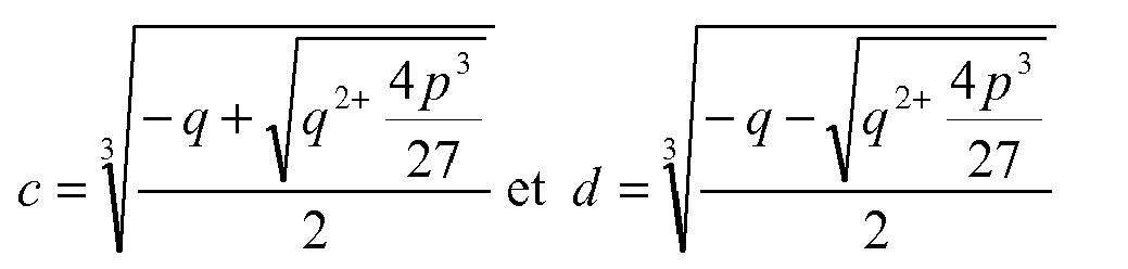
où 
![]()
with
or
Wdiff étant l'écart de régime entre le rapport (RI) initial et le rapport (RF) final,Wdiff being the ratio difference between the initial ratio (RI) and the final ratio (RF),
Pmax étant la puissance maximale admissible par le synchroniseur (18),Pmax being the maximum power allowed by the synchronizer (18),
Jap étant l'inertie des pièces tournantes soumises au couple de synchronisation, Jap étant calculée en fonction du rapport final à synchroniser,
a étant le couple de synchronisation par unité d'effort qui dépend des caractéristiques géométriques du synchroniseur.Jap being the inertia of the rotating parts subjected to the synchronization torque, Jap being calculated according to the final report to be synchronized,
a is the synchronization torque per unit of effort that depends on the geometric characteristics of the synchronizer.
Selon une mise en oeuvre, pour calculer l'écart de régime entre le rapport initial et le rapport final :
- à l'instant de la demande du changement de rapport, on mesure le régime de l'arbre primaire et le régime de l'arbre secondaire, et
- à partir des rapports de démultiplication du rapport initial et du rapport final, on calcule l'écart de régime entre ces rapports.
- at the moment of the request for the change of gear, the speed of the primary shaft and the speed of the secondary shaft are measured, and
- from the ratios of the ratio of the initial report and the final report, one calculates the difference of regime between these reports.
Selon une mise en oeuvre, la puissance maximale admissible par le synchroniseur et le couple de synchronisation par unité d'effort sont mémorisées dans le calculateur de la boîte de vitesses.According to one implementation, the maximum power allowed by the synchronizer and the synchronous torque per unit of effort are stored in the computer of the gearbox.
Selon une mise en oeuvre, le changement de rapport est commandé par le conducteur et/ou par le mode automatique de changement de rapport.According to one embodiment, the gear change is controlled by the driver and / or by the automatic gearshift mode.
L'invention sera mieux comprise à la lecture de la description qui suit et à l'examen des figures qui l'accompagnent. Ces figures ne sont données qu'à titre illustratif mais nullement limitatif de l'invention. Elles montrent :
-
figure 1 : une représentation schématique d'une chaîne de traction de véhicule mettant en oeuvre le procédé selon l'invention ; -
figure 2 : une représentation schématique d'une boîte de vitesses de la chaîne de traction du véhicule de lafigure 1 ; -
figure 3 : un diagramme de mise en oeuvre du procédé selon l'invention ; -
figure 4 : des représentations graphiques montrant respectivement l'évolution du régime de l'arbre primaire et du couple de consigne appliqué au synchroniseur lors d'un changement de rapport de vitesse.
-
figure 1 : a schematic representation of a vehicle traction chain implementing the method according to the invention; -
figure 2 : a schematic representation of a gearbox of the vehicle's power trainfigure 1 ; -
figure 3 an implementation diagram of the method according to the invention; -
figure 4 : graphical representations respectively showing the evolution of the speed of the primary shaft and the setpoint torque applied to the synchronizer during a gearshift.
Les éléments identiques conservent la même référence d'une figure à l'autre.Identical elements retain the same reference from one figure to another.
La
En variante, lorsque le véhicule 1 est hybride, la chaîne de traction est complétée par une machine 6 électrique positionnée sur l'arbre d'entrée de la boîte 4 de vitesse entre l'embrayage 3 et la boîte 4 de vitesses.Alternatively, when the vehicle 1 is hybrid, the power train is completed by an electric machine 6 positioned on the input shaft of the
La
En référence aux
Le rapport initial RI et le rapport final RF sont respectivement formés chacun par une roue 11, 12 entraînée par l'arbre 7 primaire et un pignon fou 13, 14 entraîné par l'arbre 8 secondaire.The initial ratio RI and the final report RF are each formed respectively by a
Un crabot 15 à couronne est monté sur l'arbre 8 secondaire entre les deux engrenages. Le crabot 15 est lié en rotation à l'arbre 8 et comporte une couronne 17 mobile axialement. Cette couronne 17 comporte des dents sur la périphérie de sa face radiale destinées à entrer en coopération avec des dents 13.1, 14.1 des pignons fous 13, 14.A
Lors d'un crabotage, la couronne 17 mobile se déplace vers le pignon fou du rapport à engager et engrène avec lui, de sorte que le pignon fou se lie en rotation à l'arbre 8. Lors d'un décrabotage, la couronne 17 mobile se dégage du pignon fou, de sorte que ce pignon fou n'est plus lié en rotation avec l'arbre 8.During a dog clutch, the
Le crabot 15 est également muni d'un synchroniseur 18 qui a pour rôle d'amener le crabot 15 et le pignon 13 ou 14 à engrener à des vitesses de rotation identiques avant de réaliser le crabotage.The clutch 15 is also provided with a
Pour assurer les déplacements axiaux du crabot 15, la boîte 4 de vitesses comporte un actionneur 19 commandé par le calculateur 21 de boîte de vitesses. Le calculateur 21 commande également l'ouverture et la fermeture de l'embrayage 3.To ensure the axial movements of the clutch 15, the
En outre, un premier capteur 23 de vitesse mesurant la vitesse de rotation de l'arbre 7 primaire et un deuxième capteur 25 de vitesse mesurant la vitesse de rotation de l'arbre 8 secondaire sont reliés au calculateur 21.In addition, a
Le véhicule 1 comporte également un superviseur 29 de chaîne de traction qui commande le moteur 2 thermique, l'embrayage 3 et le calculateur 21 de boîte de vitesses.The vehicle 1 also comprises a
Lorsque le rapport initial RI est engagé à l'instant t0, la couronne 17 est crabotée avec le pignon fou 14, tandis que le pignon 13 est monté fou sur l'arbre 8 secondaire. Comme représenté sur la
En référence à la
En fonction des rapports de démultiplication du rapport initial RI et du rapport final RF (indiqués par les lois 35 de passage de rapport permettant de connaître le rapport RF final), on en déduit, dans une étape 37, l'écart Wdiff entre le régime du crabot 15 et le régime du pignon 13 associé au rapport final RF à engrener. La valeur Wdiff est appliquée en entrée du bloc 39 de calcul du couple CsynMax de consigne maximal à appliquer au synchroniseur 18 pour optimiser le changement de rapport.Depending on the gear ratios of the initial ratio RI and the final report RF (indicated by the gearing laws of the report making it possible to know the final RF ratio), it is deduced, in a
Par ailleurs, le calculateur 21 de boîte de vitesses comprend dans sa mémoire 38 la puissance maximal Pmax de synchronisation admissible pour chaque synchroniseur de la boîte 4 de vitesses, ainsi que le couple « a » par unité d'effort de chaque synchroniseur (couple de synchronisation généré pour 1N d'effort) qui dépendent des caractéristiques géométriques des synchroniseurs de la boîte 4 de vitesses. Les valeurs Pmax et a relatives au synchroniseur 18 du rapport final RF sont appliquées en entrée du bloc 39.Moreover, the
Détail des calculs effectués par le bloc 39 de paramétrage du pilotage du synchroniseur 18 permettant d'obtenir CsynMax :Detail of the calculations carried out by the
En partant de l'expression suivante : 
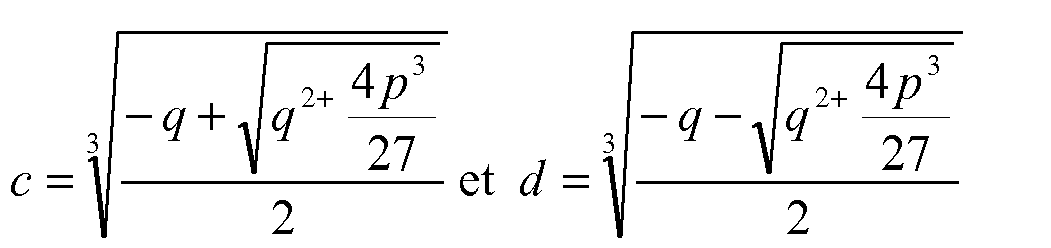
On en déduit que le couple maximal de synchronisation CsynMax à appliquer au synchroniseur en fonction de Pmax vaut : ![]()
avec 
où 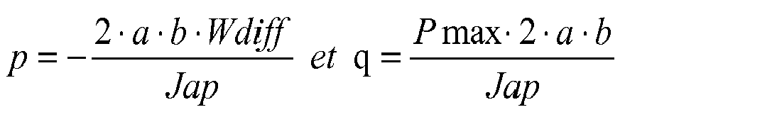
![]()
with
or
Jap étant l'inertie connue a priori des pièces tournantes soumises au couple de synchronisation, Jap étant calculée en fonction du rapport RF à synchroniser,
b étant la rampe de montée en effort de synchronisation en fonction du synchroniseur 18 et de l'écart Wdiff. Les rampes b de montée en effort de synchronisation ont des valeurs dépendantes de l'architecture de l'actionneur et des synchroniseurs. On peut donc figer une valeur en fonction de la capacité de l'actionneur, par exemple 14000 N/s.Jap being the known inertia a priori of the rotating parts subjected to the synchronization torque, Jap being calculated according to the RF ratio to be synchronized,
b being the rise ramp in synchronization force according to the
Dans une étape 40, on paramètre alors le pilotage du synchroniseur 18, de sorte qu'un couple Csyn de consigne ayant l'allure de la courbe représentée à la
A cet effet, dans une étape 41, entre t1 et t2, l'actionneur 19 est commandé de sorte que le couple Csyn de consigne soit appliqué au synchroniseur 18.For this purpose, in a
Entre t1 et t2, la vitesse du crabot 15 et la vitesse du pignon 13 fou du rapport RF final se synchronisent alors entre elles. Comme le passage du rapport RI initial au rapport RF final correspond ici à un passage montant, la synchronisation du crabot 15 avec le rapport RF final engendre une diminution du régime de l'arbre 7 primaire.Between t1 and t2, the speed of the clutch 15 and the speed of the
A l'instant t2, lorsque le régime de l'arbre 7 primaire a atteint le régime Wf du rapport final, le rapport final RF est craboté et aucun couple n'est appliqué au synchroniseur 18.At time t2, when the speed of the
En variante, pour un passage descendant, la synchronisation du crabot 15 avec le rapport RF engendre une augmentation du régime de l'arbre 7 primaire.Alternatively, for a downward passage, the synchronization of the clutch 15 with the ratio RF generates an increase in the speed of the
Claims (5)
avec
où

Pmax étant la puissance maximale admissible par le synchroniseur (18),
Jap étant l'inertie des pièces tournantes soumises au couple de synchronisation, Jap étant calculée en fonction du rapport (RF) final à synchroniser,
a étant le couple de synchronisation par unité d'effort qui dépend des caractéristiques géométriques du synchroniseur (18).A method for optimizing the control of the synchronizers of a gearbox (4) during a change of speed ratio from an initial ratio (RI) to a final ratio (RF), this method being implemented with a gearbox (4) of a vehicle, in particular a motor vehicle, comprising:
with
or
Pmax being the maximum power allowed by the synchronizer (18),
Jap being the inertia of the rotating parts subjected to the synchronization torque, Jap being calculated according to the final ratio (RF) to be synchronized,
a is the synchronization torque per unit of effort that depends on the geometrical characteristics of the synchronizer (18).
Applications Claiming Priority (1)
| Application Number | Priority Date | Filing Date | Title |
|---|---|---|---|
| FR0754519A FR2915259B1 (en) | 2007-04-17 | 2007-04-17 | METHOD OF OPTIMIZING THE CONTROL OF SYNCHRONIZERS OF A GEARBOX DURING A SHIFT CHANGE OF SPEED. |
Publications (1)
| Publication Number | Publication Date |
|---|---|
| EP1983228A1 true EP1983228A1 (en) | 2008-10-22 |
Family
ID=38683590
Family Applications (1)
| Application Number | Title | Priority Date | Filing Date |
|---|---|---|---|
| EP08305097A Withdrawn EP1983228A1 (en) | 2007-04-17 | 2008-04-10 | Method for optimising control of the synchronisers in a gearbox when shifting gears |
Country Status (2)
| Country | Link |
|---|---|
| EP (1) | EP1983228A1 (en) |
| FR (1) | FR2915259B1 (en) |
Cited By (3)
| Publication number | Priority date | Publication date | Assignee | Title |
|---|---|---|---|---|
| FR2955660A3 (en) * | 2010-01-25 | 2011-07-29 | Renault Sa | System for determining torque in conical couplers of mechanical coupling devices of automatic gear box in motor vehicle, has determination module determining transmissible torque in coupling devices to receive primary rate value |
| DE102012103288A1 (en) * | 2012-04-16 | 2013-10-17 | Dr. Ing. H.C. F. Porsche Aktiengesellschaft | Gear box has adjusting unit that applies force in axial direction on shift collar, which is smaller than blocking force and with which friction surfaces of synchronizing ring and coupling body are brought in contact |
| FR3106175A1 (en) * | 2020-01-14 | 2021-07-16 | Psa Automobiles Sa | METHOD OF OVERLOCKING A CLUTCH OF A HYBRID VEHICLE DRIVE CHAIN DURING A GEAR CHANGE |
Families Citing this family (3)
| Publication number | Priority date | Publication date | Assignee | Title |
|---|---|---|---|---|
| FR2954440A1 (en) | 2009-12-17 | 2011-06-24 | Peugeot Citroen Automobiles Sa | METHOD FOR CONTROLLING A SYNCHRONIZER IN A GEARBOX |
| FR2955637B1 (en) * | 2010-01-28 | 2012-02-10 | Peugeot Citroen Automobiles Sa | METHOD FOR CONTROLLING A SYNCHRONIZER IN A GEARBOX |
| FR2971316B1 (en) | 2011-02-07 | 2013-03-15 | Peugeot Citroen Automobiles Sa | DEVICE AND METHOD FOR CONTROLLING A DOUBLE CLUTCH GEARBOX |
Citations (8)
| Publication number | Priority date | Publication date | Assignee | Title |
|---|---|---|---|---|
| GB2119459A (en) * | 1982-04-23 | 1983-11-16 | Toyota Motor Co Ltd | Actuation system for transmission synchronizer providing regulated engagement pressure |
| US5910068A (en) * | 1995-07-19 | 1999-06-08 | Ford Global Technologies, Inc. | Countershaft automatic gearbox, in particular an automatic gearbox for motor vehicles |
| FR2799256A1 (en) | 1999-10-01 | 2001-04-06 | Mannesmann Sachs Ag | METHOD FOR SYNCHRONIZING A MOTOR VEHICLE TRANSMISSION |
| WO2001044697A1 (en) * | 1999-12-17 | 2001-06-21 | Siemens Aktiengesellschaft | Motor vehicle transmission comprising two shifting force gradients |
| DE10033811A1 (en) * | 2000-07-12 | 2002-02-07 | Daimler Chrysler Ag | Switching device has device enabling setting of actuator's control force and hence synchronizing capability depending on operating parameter(s) during synchronizing process |
| EP1205691A1 (en) * | 2000-11-09 | 2002-05-15 | Isuzu Motors Limited | Shift control device for a transmission |
| FR2849129A1 (en) * | 2002-12-19 | 2004-06-25 | Renault Sa | Driving of automatic gear box in vehicle, determining force on actuation unit in course of different phases of engagement, and adjusting displacement of gear for every speed ratio |
| US7037237B2 (en) * | 2003-03-28 | 2006-05-02 | Hitachi, Ltd. | Car control apparatus and control method |
-
2007
- 2007-04-17 FR FR0754519A patent/FR2915259B1/en not_active Expired - Fee Related
-
2008
- 2008-04-10 EP EP08305097A patent/EP1983228A1/en not_active Withdrawn
Patent Citations (8)
| Publication number | Priority date | Publication date | Assignee | Title |
|---|---|---|---|---|
| GB2119459A (en) * | 1982-04-23 | 1983-11-16 | Toyota Motor Co Ltd | Actuation system for transmission synchronizer providing regulated engagement pressure |
| US5910068A (en) * | 1995-07-19 | 1999-06-08 | Ford Global Technologies, Inc. | Countershaft automatic gearbox, in particular an automatic gearbox for motor vehicles |
| FR2799256A1 (en) | 1999-10-01 | 2001-04-06 | Mannesmann Sachs Ag | METHOD FOR SYNCHRONIZING A MOTOR VEHICLE TRANSMISSION |
| WO2001044697A1 (en) * | 1999-12-17 | 2001-06-21 | Siemens Aktiengesellschaft | Motor vehicle transmission comprising two shifting force gradients |
| DE10033811A1 (en) * | 2000-07-12 | 2002-02-07 | Daimler Chrysler Ag | Switching device has device enabling setting of actuator's control force and hence synchronizing capability depending on operating parameter(s) during synchronizing process |
| EP1205691A1 (en) * | 2000-11-09 | 2002-05-15 | Isuzu Motors Limited | Shift control device for a transmission |
| FR2849129A1 (en) * | 2002-12-19 | 2004-06-25 | Renault Sa | Driving of automatic gear box in vehicle, determining force on actuation unit in course of different phases of engagement, and adjusting displacement of gear for every speed ratio |
| US7037237B2 (en) * | 2003-03-28 | 2006-05-02 | Hitachi, Ltd. | Car control apparatus and control method |
Cited By (3)
| Publication number | Priority date | Publication date | Assignee | Title |
|---|---|---|---|---|
| FR2955660A3 (en) * | 2010-01-25 | 2011-07-29 | Renault Sa | System for determining torque in conical couplers of mechanical coupling devices of automatic gear box in motor vehicle, has determination module determining transmissible torque in coupling devices to receive primary rate value |
| DE102012103288A1 (en) * | 2012-04-16 | 2013-10-17 | Dr. Ing. H.C. F. Porsche Aktiengesellschaft | Gear box has adjusting unit that applies force in axial direction on shift collar, which is smaller than blocking force and with which friction surfaces of synchronizing ring and coupling body are brought in contact |
| FR3106175A1 (en) * | 2020-01-14 | 2021-07-16 | Psa Automobiles Sa | METHOD OF OVERLOCKING A CLUTCH OF A HYBRID VEHICLE DRIVE CHAIN DURING A GEAR CHANGE |
Also Published As
| Publication number | Publication date |
|---|---|
| FR2915259A1 (en) | 2008-10-24 |
| FR2915259B1 (en) | 2009-10-02 |
Similar Documents
| Publication | Publication Date | Title |
|---|---|---|
| EP2512894B1 (en) | Method and system for coupling an electric machine to a vehicle running gear, especially for a hybrid motor vehicle | |
| EP1983228A1 (en) | Method for optimising control of the synchronisers in a gearbox when shifting gears | |
| FR2887495A1 (en) | METHOD FOR PILOTING THE COUPLING AND DECOUPLING OF THE FIRST ENGINE AND THE SECOND ENGINE OF A PARALLEL HYBRID MOTOR POWERTRAIN | |
| EP3710732B1 (en) | Method and system for controlling a clutchless automatic transmission for a hybrid-propulsion motor vehicle | |
| EP2486307B1 (en) | Method for controlling a semiautomatic gearbox for a hybrid or dual-clutch automobile | |
| WO2012107679A1 (en) | Device and method for controlling a twin-clutch gearbox | |
| EP1983226A1 (en) | Method for standardising the gear-shifting times of a gearbox | |
| EP2098755B1 (en) | Method for shifting down with positive engine torque, for a dog gearbox | |
| EP2928715A1 (en) | Method for controlling torques when changing gear in a gearbox of a hybrid vehicle | |
| EP3117127B1 (en) | Control method during a shift of gears of a power train including an automatic transmission | |
| EP2098752B1 (en) | Method for shifting up with positive engine torque, for a dog gearbox | |
| EP2098753B1 (en) | Method for shifting up with negative engine torque, for a dog gearbox | |
| EP2098754B1 (en) | Method for shifting down with negative engine torque, for a dog gearbox | |
| WO2017153645A1 (en) | Method for checking the configuration safety of a coupling device | |
| FR2914259A1 (en) | Gear ratio changing or disengaging method for hybrid vehicle, involves controlling clutch such that heat engine transmits compensation torque to main shaft via clutch, when electric machine introduces parasite torque in degraded mode | |
| EP3668769B1 (en) | Method for learning the position of an actuator of a dual clutch transmission of a hybrid vehicle | |
| WO2011036394A1 (en) | Device for synchronising and rigidly connecting the input shafts of a dual-clutch gearbox | |
| EP2060828A1 (en) | Gearbox with torque outlet and associated shifting method | |
| EP3555500B1 (en) | Method for calculating positions for synchronising a dual-clutch transmission | |
| EP3164309B1 (en) | Method and device for controlling the coupling of shafts of a vehicle, one of which is driven by a machine, by adding an additional decreasing/increasing torque | |
| FR2904864A1 (en) | DEVICE FOR PASSING THE REVERSE MARK FOR A PILOTED GEARBOX | |
| FR2956085A1 (en) | Method for carrying out gear reduction of robotized gearbox of motor vehicle, involves performing tension application and synchronizer's actuation to carry out activated disengagement of claw as soon as gear ratio passage order is received | |
| FR2913474A1 (en) | Gear ratio changing method for hybrid vehicle, involves forming traction chain by heat engine, clutch and gear box, and clutching final ratio to separate synchronizer from gear when gearbox is synchronized with rate of final ratio | |
| EP3164310A1 (en) | Method and device for controlling the coupling of shafts of a vehicle, one of which is driven by a machine, by adding an additional monotone torque |
Legal Events
| Date | Code | Title | Description |
|---|---|---|---|
| PUAI | Public reference made under article 153(3) epc to a published international application that has entered the european phase |
Free format text: ORIGINAL CODE: 0009012 |
|
| AK | Designated contracting states |
Kind code of ref document: A1 Designated state(s): AT BE BG CH CY CZ DE DK EE ES FI FR GB GR HR HU IE IS IT LI LT LU LV MC MT NL NO PL PT RO SE SI SK TR |
|
| AX | Request for extension of the european patent |
Extension state: AL BA MK RS |
|
| 17P | Request for examination filed |
Effective date: 20081031 |
|
| AKX | Designation fees paid |
Designated state(s): AT BE BG CH CY CZ DE DK EE ES FI FR GB GR HR HU IE IS IT LI LT LU LV MC MT NL NO PL PT RO SE SI SK TR |
|
| GRAP | Despatch of communication of intention to grant a patent |
Free format text: ORIGINAL CODE: EPIDOSNIGR1 |
|
| STAA | Information on the status of an ep patent application or granted ep patent |
Free format text: STATUS: THE APPLICATION IS DEEMED TO BE WITHDRAWN |
|
| 18D | Application deemed to be withdrawn |
Effective date: 20100804 |