EP1983188A2 - Rear serviceable engine starter - Google Patents
Rear serviceable engine starter Download PDFInfo
- Publication number
- EP1983188A2 EP1983188A2 EP08153032A EP08153032A EP1983188A2 EP 1983188 A2 EP1983188 A2 EP 1983188A2 EP 08153032 A EP08153032 A EP 08153032A EP 08153032 A EP08153032 A EP 08153032A EP 1983188 A2 EP1983188 A2 EP 1983188A2
- Authority
- EP
- European Patent Office
- Prior art keywords
- engine
- housing
- gear
- motor housing
- motor
- Prior art date
- Legal status (The legal status is an assumption and is not a legal conclusion. Google has not performed a legal analysis and makes no representation as to the accuracy of the status listed.)
- Granted
Links
- 239000007858 starting material Substances 0.000 title claims abstract description 52
- 239000012530 fluid Substances 0.000 claims abstract description 82
- 238000000034 method Methods 0.000 claims description 13
- 230000004044 response Effects 0.000 claims description 12
- 238000002485 combustion reaction Methods 0.000 claims description 6
- VNWKTOKETHGBQD-UHFFFAOYSA-N methane Chemical compound C VNWKTOKETHGBQD-UHFFFAOYSA-N 0.000 description 6
- 230000013011 mating Effects 0.000 description 5
- 230000008569 process Effects 0.000 description 5
- 230000008878 coupling Effects 0.000 description 4
- 238000010168 coupling process Methods 0.000 description 4
- 238000005859 coupling reaction Methods 0.000 description 4
- 239000000446 fuel Substances 0.000 description 4
- 239000003345 natural gas Substances 0.000 description 3
- 230000008901 benefit Effects 0.000 description 2
- 230000000977 initiatory effect Effects 0.000 description 2
- 238000012546 transfer Methods 0.000 description 2
- 238000004891 communication Methods 0.000 description 1
- 230000000295 complement effect Effects 0.000 description 1
- 238000010276 construction Methods 0.000 description 1
- 238000007689 inspection Methods 0.000 description 1
- 238000012423 maintenance Methods 0.000 description 1
- 230000007246 mechanism Effects 0.000 description 1
- 238000013022 venting Methods 0.000 description 1
Images

Classifications
-
- F—MECHANICAL ENGINEERING; LIGHTING; HEATING; WEAPONS; BLASTING
- F02—COMBUSTION ENGINES; HOT-GAS OR COMBUSTION-PRODUCT ENGINE PLANTS
- F02N—STARTING OF COMBUSTION ENGINES; STARTING AIDS FOR SUCH ENGINES, NOT OTHERWISE PROVIDED FOR
- F02N7/00—Starting apparatus having fluid-driven auxiliary engines or apparatus
-
- F—MECHANICAL ENGINEERING; LIGHTING; HEATING; WEAPONS; BLASTING
- F02—COMBUSTION ENGINES; HOT-GAS OR COMBUSTION-PRODUCT ENGINE PLANTS
- F02N—STARTING OF COMBUSTION ENGINES; STARTING AIDS FOR SUCH ENGINES, NOT OTHERWISE PROVIDED FOR
- F02N15/00—Other power-operated starting apparatus; Component parts, details, or accessories, not provided for in, or of interest apart from groups F02N5/00 - F02N13/00
-
- Y—GENERAL TAGGING OF NEW TECHNOLOGICAL DEVELOPMENTS; GENERAL TAGGING OF CROSS-SECTIONAL TECHNOLOGIES SPANNING OVER SEVERAL SECTIONS OF THE IPC; TECHNICAL SUBJECTS COVERED BY FORMER USPC CROSS-REFERENCE ART COLLECTIONS [XRACs] AND DIGESTS
- Y10—TECHNICAL SUBJECTS COVERED BY FORMER USPC
- Y10T—TECHNICAL SUBJECTS COVERED BY FORMER US CLASSIFICATION
- Y10T74/00—Machine element or mechanism
- Y10T74/13—Machine starters
Landscapes
- Engineering & Computer Science (AREA)
- Chemical & Material Sciences (AREA)
- Combustion & Propulsion (AREA)
- Mechanical Engineering (AREA)
- General Engineering & Computer Science (AREA)
- Connection Of Motors, Electrical Generators, Mechanical Devices, And The Like (AREA)
Abstract
Description
- The invention relates to starters for engines, and more particularly, to starters that are serviceable while mounted to the engine.
- Internal combustion engines are typically provided with starter systems for initiating operation of the engine. Starter systems usually include an air motor driven by pressurized air and a gear system. Pressurized air is introduced to the air motor, causing a rotor to rotate. The rotor, which has a higher number of revolutions per minute (rpm) than what is needed to start the engine, is connected to the gear system, which includes one or more speed reducing gears configured to match the air motor rpm to the engine rpm. The reducing gears drive an output device such as a pinion, which is coupled to the engine. Rotation of the pinion cranks the engine, initiating operation of the engine.
- In one embodiment, the invention provides a starter comprising: a gear housing mounted near an engine to be started; a gear assembly within the gear housing; an output member aligned with a movable portion of the engine and rotatable under the influence of the gear assembly to move the movable portion to initiate operation of the engine; a motor housing mounted to the gear housing; and a fluid-driven motor within the motor housing and including a motor shaft driving rotation of the gear assembly; wherein the motor housing and motor are serviceable without changing the alignment of the output member relative to the movable portion of the engine.
- In another embodiment, the invention provides a starter for moving a movable portion of an engine to start the engine. The starter comprises a gear housing having first and second opposite ends; a gear assembly within the gear housing and including a plurality of speed-reducing gears; an output member at the first end of the gear assembly aligned with the movable portion of the engine and adapted to operably couple to the movable portion of the engine; a motor housing having a first end mounted to the second end of the gear housing and a second end opposite the first end, the second end defining a service aperture; a motive fluid inlet adapted to permit a flow of motive fluid into the motor housing; a rotor rotatably mounted within the motor housing; and a motive fluid outlet mounted to the second end of the motor housing over the service aperture, and adapted to exhaust the motive fluid to a desired destination after the motive fluid has flown through the motor housing. The rotor rotates at a first speed in response to the flow of motive fluid through the housing. The speed-reducing gears rotate in response to rotation of the rotor. The output member rotates at a second speed slower than the first speed in response to rotation of the speed-reducing gears to cause the movable portion of the engine to move and start the engine. The motive fluid outlet is removable from the second end of the motor housing without changing the alignment of the output member relative to the engine. The rotor is removable from the motor housing through the service aperture after the motive fluid outlet has been removed and without disengaging the gear housing from the engine.
- In another embodiment, the invention provides a method of servicing an engine starter that is engaged with an engine to be started. The engine starter has a gear housing mounted near the engine, a speed reducing gear assembly within the gear housing, an output member aligned with a movable portion of the engine and adapted to operably couple with the movable portion and rotatable under the influence of the gear assembly to move the movable portion to initiate operation of the engine, a motor housing mounted to the gear housing, a fluid-driven motor within the motor housing and including a motor shaft driving rotation of the speed reducing gear assembly to drive the output member, and a motive fluid outlet mounted over a service aperture of the motor housing and adapted to exhaust a motive fluid to a desired destination. The method comprises: removing the motive fluid outlet from the motor housing without changing the alignment of the output member relative to the engine; and then servicing the fluid-driven motor through the service aperture; and then installing the motive fluid outlet over the service aperture to resume operation of the engine starter.
- Other aspects of the invention will become apparent by consideration of the detailed description and accompanying drawings.
-
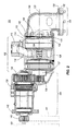
Fig. 1 is a perspective view of a starter system according to one embodiment of the invention. -
Fig. 2 is a cross-sectional view of the starter system ofFig. 1 . -
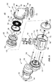
Fig. 3 is an exploded view of the starter system ofFig. 1 . - Before any embodiments of the invention are explained in detail, it is to be understood that the invention is not limited in its application to the details of construction and the arrangement of components set forth in the following description or illustrated in the following drawings. The invention is capable of other embodiments and of being practiced or of being carried out in various ways. Also, it is to be understood that the phraseology and terminology used herein is for the purpose of description and should not be regarded as limiting. The use of "including," "comprising," or "having" and variations thereof herein is meant to encompass the items listed thereafter and equivalents thereof as well as additional items. Unless specified or limited otherwise, the terms "mounted," "connected," "supported," and "coupled" and variations thereof are used broadly and encompass both direct and indirect mountings, connections, supports, and couplings. Further, "connected" and "coupled" are not restricted to physical or mechanical connections or couplings.
-
Figs. 1 - 3 illustrate astarter system 100 according to one embodiment of the invention.Starter system 100 can couple to an engine 101 (Fig. 2 ) for providing start-up cranking of theengine 101.Starter system 100 can be used with any type of engine, including but not limited to, internal combustion engines, diesel engines, and turbine and microturbine engines. -
Starter system 100 can include anair motor module 102, agear module 104 andmotive fluid outlet 106. Thegear module 104 is at the front of thestarter system 100 oriented towards theengine 101 while themotive fluid outlet 106 is at the rear of thestarter system 100 away from theengine 101. Theair motor module 102 can include anair motor housing 108 with amotive fluid inlet 110 for receiving a motive fluid, such as pressurized air, into theair motor housing 108, and aservice aperture 112 at one end of thehousing 108. Theair motor housing 108 can define anair motor chamber 114 in fluid communication with themotive fluid inlet 110 via achannel 116. - With reference to
Figs. 2 and3 , theair motor module 102 can further include arotor 122, astator 124, astator housing 128 and acontainment ring 130 arranged along thelongitudinal axis 125. As shown inFig. 3 , thestator 124 can be secured to thecontainment ring 128 against rotation by way offasteners 129. Thestator 124 can direct the flow of motive fluid against therotor 122 to cause rotation of therotor 122 with respect to thestator 124. In one example, the motive fluid may be provided in the range of 30 - 150 psig, thestator 124 may act as a supersonic nozzle, and therotor 122 may be designed to have a free turbine or "run away" speed of 65,000 rpm. Therotor 122 can be interconnected with thegear module 104 via, for example, anair motor shaft 134. Theair motor shaft 134 is supported for rotation by bearings in themotor housing 108. - With reference again to
Fig. 2 , thegear module 104 can include one or morespeed reducing gears 136 and aplanetary gear 137 within agear housing 138. Mounted at opposite ends of the reducinggears 136 and theplanetary gear 137 are theair motor shaft 134 and anoutput member 140. The reducinggears 136 and theplanetary gear 137 cause rotation of theoutput member 140 in response to rotation of theair motor shaft 134, while reducing speed and increasing torque of theoutput member 140 compared to theair motor shaft 134. In other embodiments, however, the reducinggears 136 and/or theplanetary gear 137 may be excluded from thestarter system 100. As shown inFig. 2 , thegear housing 136 is offset from thelongitudinal axis 125 so that theoutput member 140 is offset from thelongitudinal axis 125. In other embodiments, however, thegear housing 136 and/or theoutput member 140 is arranged along thelongitudinal axis 125 as well. - The
output member 140 can be, for example, a pinion. Theoutput member 140 can interface (e.g., through direct meshing with a gear, or through a belt, a chain, a plurality of gears, or any other suitable means for transferring rotation and torque) with a movable portion, mechanism, ormember 141 of theengine 101 and can be operable to move themovable portion 141 of theengine 101 in response to rotation of the reducinggears 136 in thegear housing 138. Themovable portion 141 of theengine 101 may include, for example, a crankshaft, a gear or other torque transfer member, and other movable parts. Therotor 122 rotates at a first speed in response to the flow of motive fluid through thechannel 116 andchamber 114 of themotor housing 108. Theplanetary gear 137 rotates in response to rotation of therotor 122 and drives the speed-reducinggears 136. Theoutput member 140 rotates at a second speed slower than the first speed in response to rotation of the speed-reducinggears 136 to cause themovable portion 141 of theengine 101 to move and start theengine 101. - In cases where the
movable engine portion 141 is rotatable, theoutput member 140 can be said to transfer torque from thestarter system 100 to theengine 101. This movement of themovable portion 141 of theengine 101 by theoutput member 140 can effectively start theengine 101. Thegear housing 138 8 can include aflange 142 at an end opposite theair motor shaft 134. Theflange 142 facilitates mounting thegear module 104 to theengine 101 or near theengine 101 to engage theoutput member 140 with themovable portion 141 of theengine 101. - The
motive fluid outlet 106 can provide an exhaust system for the motive fluid from thestarter system 100. Themotive fluid outlet 106 can direct the flow of motive fluid out of theair motor housing 108 after the motive fluid has flown past therotor 122. Themotive fluid outlet 106 can include anexhaust cap 143 mounted to theair motor housing 108 over theservice aperture 112. Thus, theoutput member 140 and mountingflange 142 are at a first end of thegear housing 138, a second end of the gear housing 138 (opposite the first end) is mounted to a first end of themotor housing 108, a second end of the motor housing 108 (opposite the first end) defines theservice aperture 112 and has mounted thereon theexhaust cap 143. - A
debris screen 144 can be positioned between theair motor housing 108 and theexhaust cap 143 for trapping debris. An O-ring seal 146 can also be positioned between theair motor housing 108 and theexhaust cap 143 to prevent motive fluid leakage. Theexhaust cap 143,debris screen 144 and O-ring seal 146 can be arranged along thelongitudinal axis 125 as well. - The
motive fluid outlet 106 can further include aconduit 148 for directing exhaust motive fluid away from thestarter system 100. Theconduit 148 can be, for example, an elbow. Theconduit 148 can include apipe flange 150 for mounting theconduit 148 to apipe coupling 152 to facilitate securing theconduit 148 to a pipe or other structure for directing the exhaust motive fluid to a remote location. The elbow version of theconduit 148 illustrated in the drawings may be employed in applications that use natural gas or another combustible gaseous fuel as the motive fluid, as for example, at a site that has a ready supply of such fuel for theengine 101 or another device. The pipe to which theconduit 148 is secured through thepipe coupling 152 may direct the natural gas or other combustible gaseous fuel to a flare or the combustion chamber of another device for immediate combustion, or may recapture the natural gas or other combustible gaseous fuel for future use. - In alternate embodiments of the
motive fluid outlet 106, theconduit 148 may be replaced with a diffuser mounted to theexhaust cap 143. The diffuser would lower the pressure of the motive fluid prior to venting the motive fluid to the atmosphere or ambient surroundings. Such diffuser may be particularly useful in applications using compressed air as the motive fluid. The term "desired destination" is used herein to refer to the atmosphere, conduits, flares, combustion chambers, or any other destination for the motive fluid upon flowing out of themotive fluid outlet 106. - As shown in
Fig. 3 , fourelongated fasteners 154 can extend from thegear housing 138. Thefasteners 154 can be arranged parallel to thelongitudinal axis 125. Theair motor housing 108 can include fourcomplementary passages 156 sized and shaped for receiving thefasteners 154. Thefasteners 154, when received in thepassages 156, can extend substantially the entire length of theair motor housing 108.Mating fasteners 158 can be placed over thefasteners 154 to secure theair motor module 102 to thegear module 104. Thefasteners 154 and themating fasteners 158 can be, for example, threaded fasteners such as bolts or studs and nuts. - The
exhaust cap 143 can also include fourpassages 160 for receiving thefasteners 154 so as to mount themotive fluid outlet 106 to theair motor module 102. That is, thefasteners 154 can extend through thepassages 156 and thepassages 160 with themating fasteners 158 placed over thefasteners 154 at theexhaust cap 143. Therefore, a single set offasteners 154 can be used to mount themotive fluid outlet 106 and theair motor module 102 to thegear module 104. In this regard, thefasteners 154 extend through themotor housing 108 and secure themotor housing 108 to thegear housing 138 at one end of themotor housing 108, and secure themotive fluid outlet 106 to themotor housing 108 at an opposite end of themotor housing 108. In alternate embodiments, however, separate fasteners may be employed to mount themotive fluid outlet 106 to theair motor module 102. - Access to the
air motor module 102 can be accomplished by removing themating fasteners 158 from thefasteners 154. Theexhaust cap 143 can be slid off of thefasteners 154 to remove themotive fluid outlet 106 from theair motor module 102, exposing theservice aperture 112. Then, each internal component of theair motor module 102 can be slid out of theair motor housing 108 in turn. For example, thedebris screen 144, therotor 122, thestator 124, thestator housing 128 and thecontainment ring 130 can be removed from theair motor housing 108 through theservice aperture 112. Theair motor housing 108 can also be removed by sliding theair motor housing 108 off of thefasteners 154. - Alternately, the entire
air motor module 102 can be removed with internal components substantially in their operative positions within thehousing 108, by sliding theair motor housing 108 off of the fourfasteners 154 with the internal components inside of theair motor housing 108. Alternately, theair motor module 102 may be serviced (e.g., cleaned or parts replaced) while still within themotor housing 108. As used herein, references to servicing the components of the starter "through the service aperture" include removing the components through theservice aperture 112 prior to service, or leaving the components in themotor housing 108 while servicing the components. - Throughout the dismounting or disassembling process, the
gear module 104, including theflange 142, thegear housing 138, the reducinggears 136 and theplanetary gear 137, can remain in position aligned with theengine 101 through theflange 142. Likewise, throughout this process, theoutput member 140 can remain aligned with themovable portion 141 of theengine 101. This provides a substantial advantage in terms of the time required to service theair motor module 102 in the event foreign debris becomes entrained in the motive fluid and interferes with operation of thestarter system 100 or occludes thescreen 144 between scheduled maintenance. The present invention permits the rear portion of thestarter 100 to be removed so the parts of theair motor module 102 can be cleaned, replaced, or otherwise serviced without affecting the relatively precise alignment of theoutput member 140 with respect to themovable portion 141 of theengine 101 and without having to disengage theoutput member 140 from the engine 201. As used herein, "disengage" means to operably decouple theoutput member 140 from themovable portion 141 of theengine 101 to the extent that theoutput member 140 cannot transmit sufficient torque or other force to themovable member 141 of theengine 101 to start theengine 101. - To re-assemble the
starter system 100, the process is reversed. That is, theair motor housing 108 is installed on thegear module 104 by sliding theair motor housing 108 back over thefasteners 154. The internal components of theair motor module 102 can be assembled within theair motor chamber 108 prior to installing theair motor housing 108 on thegear module 104. Alternately, the internal components of theair motor module 102, including, for example, therotor 122 and thestator 124, can be installed in theair motor housing 108 after theair motor housing 108 is slid onto thefasteners 154 by passing them through theservice aperture 112. After theair motor module 102 is in place on thefasteners 154, theexhaust cap 143 is slid over the ends of thefasteners 154 to install or mount themotive fluid outlet 106 onto theair motor module 102. Finally, themating fasteners 158 are secured to thefasteners 154. - The
starter system 100 can be configured so that themotive fluid outlet 106 can be removed from theair motor module 102 to permit access to theservice aperture 112 at the rear of thestarter system 100 without removing theair motor module 102 from thegear module 104 and without changing the alignment of thegear module 104 relative to theengine 101. Thestarter system 100 can also be configured so that the internal components of theair motor module 102, including, for example, therotor 122 and thestator 124, can be removed from theair motor housing 108 through theservice aperture 112 while themotive fluid outlet 106 is removed without removing theair motor housing 108 from thegear module 104. Finally, thestarter system 100 can also be configured so that theair motor housing 108 and/or the entireair motor module 102 can be removed from thegear module 104 without changing the alignment of thegear module 104 relative to theengine 101. - Thus, the invention provides, among other things, an engine starter that is serviceable without being removed or disengaged from the engine. Various features and advantages of the Invention are set forth in the following claims.
Attention is directed to all papers and documents which are filed concurrently with or previous to this specification in connection with this application and which are open to public inspection with this specification, and the contents of all such papers and documents are incorporated herein by reference.
All of the features disclosed in this specification (including any accompanying claims, abstract and drawings), and/or all of the steps of any method or process so disclosed, may be combined in any combination, except combinations where at least some of such features and/or steps are mutually exclusive.
Each feature disclosed in this specification (including any accompanying claims, abstract and drawings) may be replaced by alternative features serving the same, equivalent or similar purpose, unless expressly stated otherwise. Thus, unless expressly stated otherwise, each feature disclosed is one example only of a generic series of equivalent or similar features.
The invention is not restricted to the details of the foregoing embodiment(s). The invention extends to any novel one, or any novel combination, of the features disclosed in this specification (including any accompanying claims, abstract and drawings), or to any novel one, or any novel combination, of the steps of any method or process so disclosed.
Claims (15)
- A starter comprising:a gear housing mounted near an engine to be started;a gear within the gear housing;an output member in alignment with a movable portion of the engine and rotatable under the influence of the gear to move the movable portion to initiate operation of the engine;a motor housing mounted to the gear housing; anda fluid-driven motor within the motor housing and including a motor shaft driving rotation of the gear;wherein the motor housing and motor are serviceable without changing the alignment of the output member relative to the movable portion of the engine.
- The starter of claim 1, wherein the motor is serviceable without removing the motor housing from the gear housing.
- The starter of claim 2, wherein the motor shaft rotates about an axis of rotation; the starter further comprising a plurality of fasteners extending parallel to the axis of rotation to secure the motor housing to the gear housing; wherein the motor housing is removed from the gear housing by moving at least one of the motor housing and plurality of fasteners parallel to the axis of rotation and off of the gear housing.
- The starter of claim 1, further comprising a motive fluid inlet adapted to deliver a motive fluid to drive rotation of the motor shaft; and a motive fluid outlet mounted to the motor housing and adapted to exhaust the motive fluid to a desired destination; wherein the motor housing defines a service aperture; wherein the fluid outlet is mounted to the motor housing over the service aperture; and wherein the motor may be serviced through the service aperture upon removal of the fluid outlet from the motor housing.
- The starter of claim 4, further comprising a plurality of fasteners, each extending through portions of the gear housing, motor housing, and fluid outlet such that the motor housing and fluid outlet may be removed from the gear housing by moving the motor housing and fluid outlet off of the fasteners without changing the alignment of the output member relative to the movable portion of the engine.
- The starter of claim 1, wherein the fluid-driven motor includes a stator and a rotor, wherein the motor housing includes a service aperture through which at least one of the stator and the rotor can be serviced without changing the alignment of the output member relative to the movable portion of the engine.
- The starter of claim 1, wherein the gear housing is adapted to be mounted to a portion of the engine to be started.
- The starter of claim 1, wherein the gear is a speed-reducing gear assembly, wherein the motor shaft rotates at a first speed; and wherein the output member rotates at a second speed lower than the first speed in response to the motor shaft driving rotation of the speed-reducing gear assembly and the speed-reducing gear assembly driving rotation of the output member.
- A starter for moving a movable portion of an engine to start the engine, the starter comprising:a gear housing having first and second opposite ends;a gear assembly within the gear housing and including a plurality of speed-reducing gears;an output member at the first end of the gear assembly aligned with the movable portion of the engine and adapted to operably couple to the movable portion of the engine;a motor housing having a first end mounted to the second end of the gear housing and a second end opposite the first end, the second end defining a service aperture;a motive fluid inlet adapted to permit a flow of motive fluid into the motor housing;a rotor rotatably mounted within the motor housing; anda motive fluid outlet mounted to the second end of the motor housing over the service aperture, and adapted to exhaust the motive fluid to a desired destination after the motive fluid has flown through the motor housing;wherein the rotor rotates at a first speed in response to the flow of motive fluid through the housing, the speed-reducing gears rotate in response to rotation of the rotor, and the output member rotates at a second speed slower than the first speed in response to rotation of the speed-reducing gears to cause the movable portion of the engine to move and start the engine;
wherein the motive fluid outlet is removable from the second end of the motor housing without changing the alignment of the output member relative to the engine; and
wherein the rotor is removable from the motor housing through the service aperture after the motive fluid outlet has been removed and without disengaging the gear housing from the engine. - The starter of claim 9, wherein the gear housing is adapted to be mounted to an internal combustion engine.
- The starter of claim 9, wherein the rotor rotates about an axis, the starter further comprising a plurality of fasteners extending parallel to the axis to secure the motor housing to the gear assembly.
- The starter of claim 11, wherein each fastener extends through portions of each of the gear housing, motor housing, and outlet motive fluid outlet; and wherein the motor housing and motive fluid outlet may be removed from the gear housing by sliding the motor housing and motive fluid outlet off the fasteners while maintaining the fasteners secured to the gear housing.
- A method of servicing an engine starter that is engaged with an engine to be started, the engine starter having: a gear housing mounted near the engine, a speed reducing gear assembly within the gear housing, an output member aligned with and operably coupled with a movable portion of the engine and rotatable under the influence of the gear assembly to move the movable portion to initiate operation of the engine, a motor housing mounted to the gear housing, a fluid-driven motor within the motor housing and including a motor shaft driving rotation of the speed reducing gear assembly to drive the output member, and a motive fluid outlet mounted over a service aperture of the motor housing and adapted to exhaust a motive fluid to a desired destination, the method comprising:removing the motive fluid outlet from the motor housing without changing the alignment of the output member relative to the engine; and thenservicing the fluid-driven motor through the service aperture; and theninstalling the motive fluid outlet over the service aperture to resume operation of the engine starter.
- The method of claim 13, further comprising removing the motor housing from the gear housing without changing the alignment of the output member relative to the engine.
- The method of claim 13, wherein the motor housing and motive fluid outlet are secured to the gear assembly by way of common fasteners; and wherein removing the motive fluid outlet from the motor housing includes sliding the motive fluid outlet off of the common fasteners while leaving the motor housing coupled to the gear assembly by the common fasteners.
Applications Claiming Priority (1)
| Application Number | Priority Date | Filing Date | Title |
|---|---|---|---|
| US11/736,845 US7584676B2 (en) | 2007-04-18 | 2007-04-18 | Rear serviceable engine starter |
Publications (3)
| Publication Number | Publication Date |
|---|---|
| EP1983188A2 true EP1983188A2 (en) | 2008-10-22 |
| EP1983188A3 EP1983188A3 (en) | 2012-05-09 |
| EP1983188B1 EP1983188B1 (en) | 2013-07-03 |
Family
ID=39537473
Family Applications (1)
| Application Number | Title | Priority Date | Filing Date |
|---|---|---|---|
| EP08153032.1A Active EP1983188B1 (en) | 2007-04-18 | 2008-03-19 | Rear serviceable engine starter |
Country Status (2)
| Country | Link |
|---|---|
| US (1) | US7584676B2 (en) |
| EP (1) | EP1983188B1 (en) |
Families Citing this family (2)
| Publication number | Priority date | Publication date | Assignee | Title |
|---|---|---|---|---|
| US7665439B2 (en) * | 2007-05-10 | 2010-02-23 | Ingersoll Rand Company | Single piece rotor |
| CN112211764B (en) * | 2020-10-09 | 2022-04-08 | 江苏欣弘实业有限公司 | Automobile-used starter motor convenient to dimension is protected |
Citations (3)
| Publication number | Priority date | Publication date | Assignee | Title |
|---|---|---|---|---|
| US33919A (en) | 1861-12-10 | Improvement in stove-grates | ||
| US3816040A (en) | 1972-11-09 | 1974-06-11 | Stanadyne Inc | Air starter and lubricator throttle valve therefor |
| US4274292A (en) | 1979-10-11 | 1981-06-23 | Arnett Jr Robert D | Compact starter assembly |
Family Cites Families (35)
| Publication number | Priority date | Publication date | Assignee | Title |
|---|---|---|---|---|
| US1598820A (en) * | 1923-04-07 | 1926-09-07 | Gen Motors Corp | Engine-starting apparatus |
| US1760988A (en) * | 1925-11-23 | 1930-06-03 | Eclipse Machine Co | Engine starter |
| US2441990A (en) * | 1944-09-02 | 1948-05-25 | Evan A Calhoun | Starter mounting |
| US3010443A (en) * | 1959-03-19 | 1961-11-28 | Garland E Lyvers | Engine starting device |
| US3791365A (en) * | 1972-03-20 | 1974-02-12 | Ingersoll Rand Co | Air starter |
| FR2331186A1 (en) * | 1975-11-07 | 1977-06-03 | Paris & Du Rhone | IMPROVEMENTS TO ELECTRIC STARTERS |
| US4126113A (en) * | 1977-10-17 | 1978-11-21 | Sarro Manuel B | Engine air starter |
| US4362065A (en) * | 1981-10-08 | 1982-12-07 | Samar, Import And Export, Inc. | Replacement starting motor assembly |
| USRE33919E (en) * | 1985-09-26 | 1992-05-12 | Sycon Corporation | Pneumatic starter for internal combustion engine |
| KR920006243B1 (en) * | 1989-02-17 | 1992-08-01 | 미쓰비시전기주식회사 | Engine starter motor |
| JPH0317281U (en) * | 1989-06-30 | 1991-02-20 | ||
| SE465527B (en) * | 1990-02-09 | 1991-09-23 | Svenska Rotor Maskiner Ab | SCREW ROUTE MACHINE WITH ORGAN FOR AXIAL BALANCE |
| IT220454Z2 (en) * | 1990-06-20 | 1993-09-22 | Magneti Marelli Spa | ENVELOPE OF SUPPORT FOR AN ELECTRIC STARTING ENGINE OF AN INTERNAL COMBUSTION ENGINE, PARTICULARLY FOR MOTOR VEHICLES |
| JPH04183242A (en) | 1990-11-16 | 1992-06-30 | Nippondenso Co Ltd | Starter/generator |
| US5134330A (en) * | 1991-02-12 | 1992-07-28 | Milton Haas | Apparatus to replace crimp-mounted solenoids on starter motors |
| US5163335A (en) * | 1991-07-15 | 1992-11-17 | Patrick D. Isom | Universal starter motor assembly |
| JPH061777U (en) * | 1992-06-12 | 1994-01-14 | 株式会社三ツ葉電機製作所 | Starter |
| US5329896A (en) * | 1993-01-06 | 1994-07-19 | Ryobi Outdoor Products, Inc. | Replaceable recoil starter |
| US5767585A (en) * | 1993-12-27 | 1998-06-16 | Nippondenso Co., Ltd. | Starter |
| JP3133893B2 (en) * | 1994-04-28 | 2001-02-13 | 三菱電機株式会社 | Starter device |
| US5836739A (en) * | 1995-03-17 | 1998-11-17 | Rolls-Royce Plc | Gas turbine engine |
| US5831340A (en) * | 1995-05-25 | 1998-11-03 | Nippondenso Co., Ltd. | Starter with high vibration resistance construction |
| US5898229A (en) * | 1995-09-18 | 1999-04-27 | Denso Corporation | Starter with improved one-way clutch structure |
| JPH09203365A (en) * | 1996-01-26 | 1997-08-05 | Denso Corp | Stator |
| JP3669532B2 (en) | 1996-09-20 | 2005-07-06 | 株式会社デンソー | Starter |
| JP3783364B2 (en) * | 1996-11-20 | 2006-06-07 | 株式会社デンソー | Starter |
| US6109122A (en) * | 1998-11-10 | 2000-08-29 | Delco Remy International, Inc. | Starter motor assembly |
| DE19955061A1 (en) * | 1999-11-15 | 2001-05-23 | Bosch Gmbh Robert | Starting system for an internal combustion engine |
| JP3838868B2 (en) * | 2000-12-05 | 2006-10-25 | 株式会社デンソー | Engine starter |
| US6559566B2 (en) * | 2001-02-12 | 2003-05-06 | Emerson Electric Co. | End shield constructed with a separate component holder |
| US6633099B2 (en) * | 2001-12-05 | 2003-10-14 | Delco Remy America, Inc. | Engagement and disengagement mechanism for a coaxial starter motor assembly |
| JP4039208B2 (en) * | 2002-10-24 | 2008-01-30 | 株式会社デンソー | Starter for internal combustion engine |
| KR20040093588A (en) * | 2003-04-30 | 2004-11-06 | 발레오전장시스템스코리아 주식회사 | A housing assembly structure of a starter motor for a vehicles |
| JP4111053B2 (en) * | 2003-05-16 | 2008-07-02 | 株式会社デンソー | Starter |
| US6969235B2 (en) * | 2003-05-19 | 2005-11-29 | Honeywell International, Inc. | Air turbine starter with angular contact thrust bearing |
-
2007
- 2007-04-18 US US11/736,845 patent/US7584676B2/en active Active
-
2008
- 2008-03-19 EP EP08153032.1A patent/EP1983188B1/en active Active
Patent Citations (3)
| Publication number | Priority date | Publication date | Assignee | Title |
|---|---|---|---|---|
| US33919A (en) | 1861-12-10 | Improvement in stove-grates | ||
| US3816040A (en) | 1972-11-09 | 1974-06-11 | Stanadyne Inc | Air starter and lubricator throttle valve therefor |
| US4274292A (en) | 1979-10-11 | 1981-06-23 | Arnett Jr Robert D | Compact starter assembly |
Also Published As
| Publication number | Publication date |
|---|---|
| US20080257295A1 (en) | 2008-10-23 |
| US7584676B2 (en) | 2009-09-08 |
| EP1983188B1 (en) | 2013-07-03 |
| EP1983188A3 (en) | 2012-05-09 |
Similar Documents
| Publication | Publication Date | Title |
|---|---|---|
| US11313246B2 (en) | Gas turbine engine wash system | |
| US8347637B2 (en) | Accessory gearbox with internal layshaft | |
| US10823080B2 (en) | Dual accessory gearbox | |
| JP4853973B2 (en) | Turbojet engine accessory gearbox drive shaft, modular auxiliary accessory | |
| EP2591219B1 (en) | Method and architecture for recombining the power of a turbomachine | |
| US7040082B2 (en) | Assistance and emergency drive for electrically-driven accessories | |
| US6851267B2 (en) | Compact quick attach starter-generator installation | |
| US8490411B2 (en) | Axial accessory gearbox | |
| RU2476701C2 (en) | Gas turbine engine with auxiliary equipment unit gearing drive, and method of mounting said engine | |
| CN105745400A (en) | Front enclosure which is sealed during the modular dismantling of a turbojet with reduction gear | |
| CA2553245A1 (en) | Pto assembly for a gas turbine engine | |
| EP1711700A1 (en) | Compact configuration for attaching a fuel pump or other accessory to an accessory gearbox | |
| GB2411437A (en) | Aircraft gas turbine engine | |
| EP3964700A1 (en) | Split compressor gas turbine engine | |
| EP1983188B1 (en) | Rear serviceable engine starter | |
| WO2008044973A1 (en) | A device for and a method of starting a gas turbine engine | |
| CA2551904C (en) | Scavenge pump system and method | |
| US7665439B2 (en) | Single piece rotor | |
| US10850860B1 (en) | Internal combustion engines with unidirectional compounding drives | |
| EP2826965B1 (en) | Removing of blow-by gas out of crankcase without auxiliary drive | |
| RU2266419C2 (en) | Air-jet diesel engine | |
| PL231367B1 (en) | Auxiliary starter for transferring to the main shaft - directly connected with the HPC shaft of the aeroderivate jet engine |
Legal Events
| Date | Code | Title | Description |
|---|---|---|---|
| PUAI | Public reference made under article 153(3) epc to a published international application that has entered the european phase |
Free format text: ORIGINAL CODE: 0009012 |
|
| AK | Designated contracting states |
Kind code of ref document: A2 Designated state(s): AT BE BG CH CY CZ DE DK EE ES FI FR GB GR HR HU IE IS IT LI LT LU LV MC MT NL NO PL PT RO SE SI SK TR |
|
| AX | Request for extension of the european patent |
Extension state: AL BA MK RS |
|
| PUAL | Search report despatched |
Free format text: ORIGINAL CODE: 0009013 |
|
| AK | Designated contracting states |
Kind code of ref document: A3 Designated state(s): AT BE BG CH CY CZ DE DK EE ES FI FR GB GR HR HU IE IS IT LI LT LU LV MC MT NL NO PL PT RO SE SI SK TR |
|
| AX | Request for extension of the european patent |
Extension state: AL BA MK RS |
|
| RIC1 | Information provided on ipc code assigned before grant |
Ipc: F02N 15/00 20060101ALI20120404BHEP Ipc: F02N 7/00 20060101AFI20120404BHEP |
|
| 17P | Request for examination filed |
Effective date: 20121003 |
|
| AKX | Designation fees paid |
Designated state(s): DE FR GB IT SE |
|
| GRAP | Despatch of communication of intention to grant a patent |
Free format text: ORIGINAL CODE: EPIDOSNIGR1 |
|
| GRAS | Grant fee paid |
Free format text: ORIGINAL CODE: EPIDOSNIGR3 |
|
| GRAA | (expected) grant |
Free format text: ORIGINAL CODE: 0009210 |
|
| AK | Designated contracting states |
Kind code of ref document: B1 Designated state(s): DE FR GB IT SE |
|
| REG | Reference to a national code |
Ref country code: GB Ref legal event code: FG4D |
|
| REG | Reference to a national code |
Ref country code: DE Ref legal event code: R096 Ref document number: 602008025680 Country of ref document: DE Effective date: 20130829 |
|
| PG25 | Lapsed in a contracting state [announced via postgrant information from national office to epo] |
Ref country code: SE Free format text: LAPSE BECAUSE OF FAILURE TO SUBMIT A TRANSLATION OF THE DESCRIPTION OR TO PAY THE FEE WITHIN THE PRESCRIBED TIME-LIMIT Effective date: 20130703 |
|
| PLBE | No opposition filed within time limit |
Free format text: ORIGINAL CODE: 0009261 |
|
| STAA | Information on the status of an ep patent application or granted ep patent |
Free format text: STATUS: NO OPPOSITION FILED WITHIN TIME LIMIT |
|
| 26N | No opposition filed |
Effective date: 20140404 |
|
| REG | Reference to a national code |
Ref country code: DE Ref legal event code: R097 Ref document number: 602008025680 Country of ref document: DE Effective date: 20140404 |
|
| REG | Reference to a national code |
Ref country code: FR Ref legal event code: PLFP Year of fee payment: 9 |
|
| REG | Reference to a national code |
Ref country code: FR Ref legal event code: PLFP Year of fee payment: 10 |
|
| REG | Reference to a national code |
Ref country code: FR Ref legal event code: PLFP Year of fee payment: 11 |
|
| REG | Reference to a national code |
Ref country code: GB Ref legal event code: 732E Free format text: REGISTERED BETWEEN 20200806 AND 20200812 |
|
| REG | Reference to a national code |
Ref country code: DE Ref legal event code: R082 Ref document number: 602008025680 Country of ref document: DE Representative=s name: MURGITROYD GERMANY PATENTANWALTSGESELLSCHAFT M, DE Ref country code: DE Ref legal event code: R082 Ref document number: 602008025680 Country of ref document: DE Ref country code: DE Ref legal event code: R082 Ref document number: 602008025680 Country of ref document: DE Representative=s name: MURGITROYD & COMPANY, DE |
|
| REG | Reference to a national code |
Ref country code: DE Ref legal event code: R082 Ref document number: 602008025680 Country of ref document: DE Representative=s name: MURGITROYD GERMANY PATENTANWALTSGESELLSCHAFT M, DE Ref country code: DE Ref legal event code: R081 Ref document number: 602008025680 Country of ref document: DE Owner name: INGERSOLL-RAND INDUSTRIAL U.S., INC. (N.D.GES., US Free format text: FORMER OWNER: INGERSOLL-RAND COMPANY, MONTVALE, N.J., US Ref country code: DE Ref legal event code: R082 Ref document number: 602008025680 Country of ref document: DE Representative=s name: MURGITROYD & COMPANY, DE |
|
| PGFP | Annual fee paid to national office [announced via postgrant information from national office to epo] |
Ref country code: GB Payment date: 20220328 Year of fee payment: 15 |
|
| PGFP | Annual fee paid to national office [announced via postgrant information from national office to epo] |
Ref country code: FR Payment date: 20230321 Year of fee payment: 16 |
|
| PGFP | Annual fee paid to national office [announced via postgrant information from national office to epo] |
Ref country code: IT Payment date: 20230329 Year of fee payment: 16 |
|
| P01 | Opt-out of the competence of the unified patent court (upc) registered |
Effective date: 20230523 |
|
| GBPC | Gb: european patent ceased through non-payment of renewal fee |
Effective date: 20230319 |
|
| PG25 | Lapsed in a contracting state [announced via postgrant information from national office to epo] |
Ref country code: GB Free format text: LAPSE BECAUSE OF NON-PAYMENT OF DUE FEES Effective date: 20230319 |
|
| PG25 | Lapsed in a contracting state [announced via postgrant information from national office to epo] |
Ref country code: GB Free format text: LAPSE BECAUSE OF NON-PAYMENT OF DUE FEES Effective date: 20230319 |
|
| PGFP | Annual fee paid to national office [announced via postgrant information from national office to epo] |
Ref country code: DE Payment date: 20240326 Year of fee payment: 17 |