EP1983141A2 - Ébauche de paroi de porte moulée, et son procédé de formation - Google Patents
Ébauche de paroi de porte moulée, et son procédé de formation Download PDFInfo
- Publication number
- EP1983141A2 EP1983141A2 EP08005453A EP08005453A EP1983141A2 EP 1983141 A2 EP1983141 A2 EP 1983141A2 EP 08005453 A EP08005453 A EP 08005453A EP 08005453 A EP08005453 A EP 08005453A EP 1983141 A2 EP1983141 A2 EP 1983141A2
- Authority
- EP
- European Patent Office
- Prior art keywords
- door facing
- blank
- receiving areas
- major surface
- door
- Prior art date
- Legal status (The legal status is an assumption and is not a legal conclusion. Google has not performed a legal analysis and makes no representation as to the accuracy of the status listed.)
- Withdrawn
Links
- 238000000034 method Methods 0.000 title claims abstract description 12
- 239000000758 substrate Substances 0.000 claims description 17
- 238000004049 embossing Methods 0.000 claims description 12
- 239000002131 composite material Substances 0.000 claims description 8
- 238000000465 moulding Methods 0.000 claims description 8
- 238000009966 trimming Methods 0.000 claims description 6
- 229910052751 metal Inorganic materials 0.000 claims description 4
- 239000002184 metal Substances 0.000 claims description 4
- 229920000642 polymer Polymers 0.000 claims description 4
- 239000011324 bead Substances 0.000 claims description 3
- 230000000295 complement effect Effects 0.000 claims description 2
- 239000000463 material Substances 0.000 description 4
- 239000000835 fiber Substances 0.000 description 3
- 238000004519 manufacturing process Methods 0.000 description 3
- 239000011230 binding agent Substances 0.000 description 2
- 238000012986 modification Methods 0.000 description 2
- 230000004048 modification Effects 0.000 description 2
- 239000011347 resin Substances 0.000 description 2
- 229920005989 resin Polymers 0.000 description 2
- 239000007787 solid Substances 0.000 description 2
- 239000003677 Sheet moulding compound Substances 0.000 description 1
- 229910000831 Steel Inorganic materials 0.000 description 1
- 230000006978 adaptation Effects 0.000 description 1
- 229910052782 aluminium Inorganic materials 0.000 description 1
- XAGFODPZIPBFFR-UHFFFAOYSA-N aluminium Chemical compound [Al] XAGFODPZIPBFFR-UHFFFAOYSA-N 0.000 description 1
- 238000005452 bending Methods 0.000 description 1
- 230000006835 compression Effects 0.000 description 1
- 238000007906 compression Methods 0.000 description 1
- 238000007796 conventional method Methods 0.000 description 1
- 238000005520 cutting process Methods 0.000 description 1
- 230000000994 depressogenic effect Effects 0.000 description 1
- 239000011152 fibreglass Substances 0.000 description 1
- 239000002657 fibrous material Substances 0.000 description 1
- 238000003825 pressing Methods 0.000 description 1
- 238000007493 shaping process Methods 0.000 description 1
- 239000010959 steel Substances 0.000 description 1
- 239000002023 wood Substances 0.000 description 1
Images


Classifications
-
- E—FIXED CONSTRUCTIONS
- E06—DOORS, WINDOWS, SHUTTERS, OR ROLLER BLINDS IN GENERAL; LADDERS
- E06B—FIXED OR MOVABLE CLOSURES FOR OPENINGS IN BUILDINGS, VEHICLES, FENCES OR LIKE ENCLOSURES IN GENERAL, e.g. DOORS, WINDOWS, BLINDS, GATES
- E06B3/00—Window sashes, door leaves, or like elements for closing wall or like openings; Layout of fixed or moving closures, e.g. windows in wall or like openings; Features of rigidly-mounted outer frames relating to the mounting of wing frames
- E06B3/70—Door leaves
- E06B3/7001—Coverings therefor; Door leaves imitating traditional raised panel doors, e.g. engraved or embossed surfaces, with trim strips applied to the surfaces
-
- E—FIXED CONSTRUCTIONS
- E06—DOORS, WINDOWS, SHUTTERS, OR ROLLER BLINDS IN GENERAL; LADDERS
- E06B—FIXED OR MOVABLE CLOSURES FOR OPENINGS IN BUILDINGS, VEHICLES, FENCES OR LIKE ENCLOSURES IN GENERAL, e.g. DOORS, WINDOWS, BLINDS, GATES
- E06B3/00—Window sashes, door leaves, or like elements for closing wall or like openings; Layout of fixed or moving closures, e.g. windows in wall or like openings; Features of rigidly-mounted outer frames relating to the mounting of wing frames
- E06B3/70—Door leaves
- E06B3/72—Door leaves consisting of frame and panels, e.g. of raised panel type
- E06B3/74—Door leaves consisting of frame and panels, e.g. of raised panel type with wooden panels or frame
-
- E—FIXED CONSTRUCTIONS
- E06—DOORS, WINDOWS, SHUTTERS, OR ROLLER BLINDS IN GENERAL; LADDERS
- E06B—FIXED OR MOVABLE CLOSURES FOR OPENINGS IN BUILDINGS, VEHICLES, FENCES OR LIKE ENCLOSURES IN GENERAL, e.g. DOORS, WINDOWS, BLINDS, GATES
- E06B3/00—Window sashes, door leaves, or like elements for closing wall or like openings; Layout of fixed or moving closures, e.g. windows in wall or like openings; Features of rigidly-mounted outer frames relating to the mounting of wing frames
- E06B3/70—Door leaves
- E06B3/72—Door leaves consisting of frame and panels, e.g. of raised panel type
- E06B3/78—Door leaves consisting of frame and panels, e.g. of raised panel type with panels of plastics
-
- B—PERFORMING OPERATIONS; TRANSPORTING
- B29—WORKING OF PLASTICS; WORKING OF SUBSTANCES IN A PLASTIC STATE IN GENERAL
- B29C—SHAPING OR JOINING OF PLASTICS; SHAPING OF MATERIAL IN A PLASTIC STATE, NOT OTHERWISE PROVIDED FOR; AFTER-TREATMENT OF THE SHAPED PRODUCTS, e.g. REPAIRING
- B29C59/00—Surface shaping of articles, e.g. embossing; Apparatus therefor
- B29C59/02—Surface shaping of articles, e.g. embossing; Apparatus therefor by mechanical means, e.g. pressing
-
- B—PERFORMING OPERATIONS; TRANSPORTING
- B29—WORKING OF PLASTICS; WORKING OF SUBSTANCES IN A PLASTIC STATE IN GENERAL
- B29L—INDEXING SCHEME ASSOCIATED WITH SUBCLASS B29C, RELATING TO PARTICULAR ARTICLES
- B29L2031/00—Other particular articles
- B29L2031/724—Doors
-
- B—PERFORMING OPERATIONS; TRANSPORTING
- B30—PRESSES
- B30B—PRESSES IN GENERAL
- B30B7/00—Presses characterised by a particular arrangement of the pressing members
- B30B7/02—Presses characterised by a particular arrangement of the pressing members having several platens arranged one above the other
-
- B—PERFORMING OPERATIONS; TRANSPORTING
- B32—LAYERED PRODUCTS
- B32B—LAYERED PRODUCTS, i.e. PRODUCTS BUILT-UP OF STRATA OF FLAT OR NON-FLAT, e.g. CELLULAR OR HONEYCOMB, FORM
- B32B3/00—Layered products comprising a layer with external or internal discontinuities or unevennesses, or a layer of non-planar shape; Layered products comprising a layer having particular features of form
- B32B3/26—Layered products comprising a layer with external or internal discontinuities or unevennesses, or a layer of non-planar shape; Layered products comprising a layer having particular features of form characterised by a particular shape of the outline of the cross-section of a continuous layer; characterised by a layer with cavities or internal voids ; characterised by an apertured layer
- B32B3/30—Layered products comprising a layer with external or internal discontinuities or unevennesses, or a layer of non-planar shape; Layered products comprising a layer having particular features of form characterised by a particular shape of the outline of the cross-section of a continuous layer; characterised by a layer with cavities or internal voids ; characterised by an apertured layer characterised by a layer formed with recesses or projections, e.g. hollows, grooves, protuberances, ribs
-
- B—PERFORMING OPERATIONS; TRANSPORTING
- B44—DECORATIVE ARTS
- B44C—PRODUCING DECORATIVE EFFECTS; MOSAICS; TARSIA WORK; PAPERHANGING
- B44C1/00—Processes, not specifically provided for elsewhere, for producing decorative surface effects
- B44C1/24—Pressing or stamping ornamental designs on surfaces
-
- E—FIXED CONSTRUCTIONS
- E06—DOORS, WINDOWS, SHUTTERS, OR ROLLER BLINDS IN GENERAL; LADDERS
- E06B—FIXED OR MOVABLE CLOSURES FOR OPENINGS IN BUILDINGS, VEHICLES, FENCES OR LIKE ENCLOSURES IN GENERAL, e.g. DOORS, WINDOWS, BLINDS, GATES
- E06B3/00—Window sashes, door leaves, or like elements for closing wall or like openings; Layout of fixed or moving closures, e.g. windows in wall or like openings; Features of rigidly-mounted outer frames relating to the mounting of wing frames
- E06B3/70—Door leaves
- E06B2003/7096—Door leaves with possibilities to alter the extension of the door
-
- Y—GENERAL TAGGING OF NEW TECHNOLOGICAL DEVELOPMENTS; GENERAL TAGGING OF CROSS-SECTIONAL TECHNOLOGIES SPANNING OVER SEVERAL SECTIONS OF THE IPC; TECHNICAL SUBJECTS COVERED BY FORMER USPC CROSS-REFERENCE ART COLLECTIONS [XRACs] AND DIGESTS
- Y10—TECHNICAL SUBJECTS COVERED BY FORMER USPC
- Y10T—TECHNICAL SUBJECTS COVERED BY FORMER US CLASSIFICATION
- Y10T156/00—Adhesive bonding and miscellaneous chemical manufacture
- Y10T156/12—Surface bonding means and/or assembly means with cutting, punching, piercing, severing or tearing
-
- Y—GENERAL TAGGING OF NEW TECHNOLOGICAL DEVELOPMENTS; GENERAL TAGGING OF CROSS-SECTIONAL TECHNOLOGIES SPANNING OVER SEVERAL SECTIONS OF THE IPC; TECHNICAL SUBJECTS COVERED BY FORMER USPC CROSS-REFERENCE ART COLLECTIONS [XRACs] AND DIGESTS
- Y10—TECHNICAL SUBJECTS COVERED BY FORMER USPC
- Y10T—TECHNICAL SUBJECTS COVERED BY FORMER US CLASSIFICATION
- Y10T428/00—Stock material or miscellaneous articles
- Y10T428/24—Structurally defined web or sheet [e.g., overall dimension, etc.]
- Y10T428/24479—Structurally defined web or sheet [e.g., overall dimension, etc.] including variation in thickness
- Y10T428/2457—Parallel ribs and/or grooves
-
- Y—GENERAL TAGGING OF NEW TECHNOLOGICAL DEVELOPMENTS; GENERAL TAGGING OF CROSS-SECTIONAL TECHNOLOGIES SPANNING OVER SEVERAL SECTIONS OF THE IPC; TECHNICAL SUBJECTS COVERED BY FORMER USPC CROSS-REFERENCE ART COLLECTIONS [XRACs] AND DIGESTS
- Y10—TECHNICAL SUBJECTS COVERED BY FORMER USPC
- Y10T—TECHNICAL SUBJECTS COVERED BY FORMER US CLASSIFICATION
- Y10T428/00—Stock material or miscellaneous articles
- Y10T428/24—Structurally defined web or sheet [e.g., overall dimension, etc.]
- Y10T428/24628—Nonplanar uniform thickness material
- Y10T428/24736—Ornamental design or indicia
Definitions
- the present invention is directed to a door facing blank having a first major surface with a design element formed therein, and an opposite second major surface. At least three longitudinally extending spaced stile receiving areas are disposed on the second major surface. Two of the stile receiving areas define a first width, and three of the stile receiving areas define a second width greater than the first width.
- the door facing blank may be trimmed to form a door facing having a selected width.
- Hollow and solid core doors typically include a perimeter frame with first and second door facings secured to opposite sides of the frame.
- the door facings may be formed from composites of cellulosic material and resin binder, polymers, or metal.
- Hollow or solid core doors may be of the 'flush' type, that is, one that is flat or planar on both major surfaces.
- one or both door facings may include contoured portions, architectural elements or textures.
- a door facing may be molded to include contoured portions simulating stiles, rails and panels.
- Molded and architectural features are often desirable to consumers, and may be molded or embossed into a blank during compression.
- a different die set is typically required for each size and length door facing.
- a plurality of die sets are typically required to form door facings of different widths, even if the molded design is similar on all of the different width door facings due to the position and configuration of the molded portions on the facing.
- different die sets are typically required for different length door facings, even if the molded design configuration is similar on all facings.
- molded door facings having contoured or architectural features are relatively expensive because the capital cost is quite high due to the need for dies, presses, and the like for each specific door facing size.
- the flat or planar facings used for flush doors are relatively inexpensive, but do not provide the aesthetic features often desired by consumers.
- the present invention is directed to a door facing blank having a first major surface intended to be exteriorly disposed and an opposite second major surface intended to be interiorly disposed.
- First and second planar, spaced stile receiving areas are disposed on the second major surface.
- a central portion is intermediate the first and second stile receiving areas.
- a plurality of grooves are formed in the first major surface and define a design element. At least one of the grooves includes an embossed portion disposed in the first major surface opposite the first and second planar spaced stile receiving areas and a molded portion disposed in the central portion.
- At least one of the first and second spaced stile receiving areas are trimmable to form a door facing having a selected width.
- the present invention also relates to a door facing blank having a first major surface intended to be exteriorly disposed and an opposite second major surface intended to be interiorly disposed.
- a design element is formed in the first major surface.
- At least three longitudinally extending spaced stile receiving areas are disposed on the second major surface. Two of the stile receiving areas define a first width, and three of the stile receiving areas define a second width greater than the first width.
- the door facing blank may be trimmed to form a door facing having a selected width and having a first one of the stile receiving areas adjacent a first longitudinal edge of the door facing, and a second one of the stile receiving areas adjacent a second longitudinal edge of the door facing.
- a method of forming a door is also disclosed.
- a perimeter frame having first and second spaced stiles defining a width is provided.
- First and second door facing blanks are provided. Each of the blanks has a first major surface and an opposite second major surface, a design element formed in the first major surface, and a plurality of longitudinally extending spaced stile receiving areas disposed on the second major surface. First and second stile receiving areas are selected that are spaced by a distance corresponding to the width of the first and second spaced stiles.
- the first and second door facing blanks are trimmed adjacent the selected first and second stile receiving areas to form first and second door facings having selected widths.
- the first and second door facings are then secured to opposite sides of the perimeter frame, thereby forming a door.
- the present invention also relates to a mold press for forming the disclosed door facing blank.
- the mold press includes an upper die mold and a spaced lower die mold, which form a mold cavity for molding a substrate to form the door facing blank.
- the upper die mold has a plurality of protrusions disposed in a first portion and embossing features disposed in a second portion.
- the lower die mold has a plurality of depressions aligned with and complementary to the plurality of protrusions for forming molded features in the substrate, and planar portions aligned with the embossing features for forming stile receiving areas in the substrate.
- the die mold forms a door facing blank having at least three longitudinally extending spaced stile receiving areas on an intended interior surface thereof, two of the stile receiving areas defining a first width, and three of the stile receiving areas defining a second width greater than the first width.
- the door facing blank may be trimmed to form a door facing having a selected width.
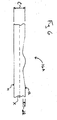
- a door facing blank 10 includes a first major surface 12 intended to be exteriorly disposed and an opposite second major surface 14 intended to be interiorly disposed.
- a design element is formed in first major surface 12.
- An exemplary design element according to an embodiment of the present invention is shown in Figures 1 and 2 .
- the design element includes molded grooves 16 formed in a central portion 18 of blank 10, as shown in Figures 1-3 . Molded grooves 16 extend outwardly from second major surface 14. Molded grooves 16 may include an upwardly extending central bead 20 intermediate side walls 22, 24.
- the design element may also include embossed grooves 16A formed in first and second side portions 26, 28 of blank 10, as shown in Figures 1 and 4 .
- Embossed grooves 16A may include upwardly extending central beads 20A intermediate side walls 22A, 24A. While embossed grooves 16A extend into first major surface 12, second major surface 14 is preferably substantially planar opposite any embossed grooves 16A, such as in first and second side portions 26, 28, as shown in Figures 2 and 4 .
- molding a cellulosic substrate involves re-shaping the material using heat and pressure.
- the cellulosic substrate is re-shaped by stretching and bending the fibers of the cellulosic material during the molding process.
- a geometric change in the central plane of the substrate occurs during the molding process.
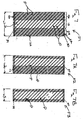
- the central plane of a planar substrate is defined at the center of the caliper of the substrate, shown by dashed line X in Figure 5 .
- the depth d1 of a molded portion may be greater than the total caliper C of the substrate.
- molded grooves 16 may be molded to a depth of about 0.07 inch or more, while the total caliper of blank 10 may be between about 0.1 to 0.2 inches.
- molded grooves 16 are molded to a depth of between about 0.1 inch and about 0.5 inch.
- the depth d1 of molded grooves 16 may be greater than the total caliper C of blank 10.
- a portion of molded grooves 16 extends outwardly from the plane of second major surface 14.
- embossing typically involves pressing a substrate with a textured roll or plate. This process results in a slightly contoured surface having a relatively shallow profile depth, but without a geometric change in the central plane X of the substrate, as shown in Figure 6 .
- the depth of a depressed portion that has been embossed into a cellulosic fiber substrate is typically less than 1/3 of the total caliper of the substrate prior to embossing.
- the central plane X of the cellulosic fiber substrate is not altered during the embossing process when forming embossed grooves 16A.
- embossed grooves 16A are simply pressed inwards toward the central plane, so that the corresponding portion of second major surface 14 opposite embossed grooves 15A is substantially planar, as shown in Figures 2, 4 and 6 .
- grooves 16A may be embossed into first major surface 12 to a depth d2 of about 0.005 inch or more. More preferably, embossed grooves 16A are embossed to a depth d2 of between about 0.005 inch and about 0.07 inch.
- Molded grooves 16 are preferably configured and positioned on blank 10 so that second major surface 14 is substantially planar on first and second side portions 26, 28. In this way, stiles of a perimeter frame may be easily secured to planar portions of second major surface 14 at a selected position on first and second side portions 26, 28.
- first and second side portions 26, 28 have a width greater than the width of the stiles to be secured thereto. In this way, blank 10 may be trimmed to a selected width, while maintaining a portion of each of first and second side portions 26, 28 for accommodating stiles.
- molded grooves 16 and embossed grooves 16A are configured so that even if first and/or second side portions 26, 28 are trimmed, the remaining design element on the resulting door facing is aesthetically acceptable.
- embossed grooves 16A extend outwardly from and linearly with corresponding molded grooves 16.
- the resulting design element includes a plurality of parallel grooves 16, 16A extending angularly across the entire first major surface 12, giving the appearance of a door formed from a plurality of slanted planks P. Because first and second side portions 26, 28 are embossed, they may be trimmed to achieve a door facing having a selected width, while first major surface 12 maintains the same appearance.
- blank 10 having molded grooves 16 in central portion 18 and embossed grooves 16A in side portions 26, 28 may be molded to have a width w1 corresponding to a standard commercial width w1 of door facing F1, e.g. a door facing having a width of about 36 inches.
- blank 10 may be used as door facing F1, as shown in Figure 7 .
- First side portion 26 of blank 10 may be trimmed to form a door facing F2 having a second width w2, as shown in Figure 7A .
- Both first and second side portions 26, 28 may be trimmed to form a door facing F3 having a third width w3, as shown in Figure 7B .
- first major surface 12 which resembles a plurality of slanted planks P, is maintained on door facings F2 and F3, despite first and/or second portions 26, 28 having been trimmed, and even if unequal portions of first and second portions 26, 28 have been trimmed.
- Blank 10 may be trimmed using any conventional cutting method to form a door facing having any one of a plurality of different widths due to the configuration and positioning of molded grooves 16 and embossed grooves 16A, which maintain an aesthetically acceptable design element on all door facing widths. For example, predetermined portions of blank 10 may be trimmed to form a door facing having one of eleven selectable widths. Conventional methods of forming door facings having the same molded design element but different widths typically require a separate die mold for each width. Blank 10 therefore substantially reduces manufacturing costs because a plurality of different width door facings may be formed from the same blank 10, which is formed from a single die mold.
- first and second side portions 26, 28 are substantially greater than the stiles to be secure thereto.
- a portion of each of first and second side portions 26, 28 remains after trimming and has a width at least equal to the width of the stile to be secured thereto, so that a substantially planar longitudinally extending surface is provided for receiving the corresponding stile.
- Blank 10 also preferably includes a first rail receiving area 30 adjacent a first end 32 of blank 10, and a second rail receiving area 34 adjacent a second end 36 of blank 10, as shown in Figures 1 and 7-7B .
- Rail receiving areas 30, 34 preferably extend horizontally across blank 10, perpendicular to longitudinal edges 38, 40 thereof. As such, rail receiving areas 30, 34 extend through first and second side portions 26, 28 as well as central portion 18.
- portions of the design element formed in first major surface 12 and extending into rail receiving areas 30, 34 are embossed (e.g. embossed grooves 16A), as opposed to molded (e.g. molded grooves 16). In this way, the corresponding second major surface 14 opposite rail receiving areas 30, 34 is substantially planar for accommodating the rails of a perimeter frame.
- Blank 10 may also be configured so that the design element does not extend into rail receiving areas 30, 34.
- first major surface 12 may include upper and lower planar portions resembling rails.
- rail receiving areas 30, 34 may be configured to be wider than the width of the rails to be secured thereto, so that portions of rail receiving areas 30, 34 may be trimmed while still maintaining a portion sufficient for accommodating the rails of the perimeter frame. In this way, blank 10 may be trimmed to form a door facing having a selected length as well a selected width.
- design element formed in blank 10 is not limited to a specific configuration and position of slanted grooves 16,16A shown in Figures 1, 2 and 7-7B .
- specific configurations of grooves 16, 16A are not limited to that shown in Figures 3 and 4 . Rather, various configurations of a design element are possible with the present invention.
- a blank 10A may be formed having a design element including a plurality of grooves 16 extending parallel to longitudinal edges 38, 40, as shown in Figure 8 .
- Grooves 16 may be evenly spaced to define a plurality of longitudinally extending planks P1 having uniform widths. Planks P1 may extend from first end 32 of blank 10A to second end 36.
- the design element of blank 10A may include all molded grooves 16, as shown in Figure 9 . Because molded grooves 16 include portions extending outwardly from second major surface 14, molded grooves 16 are preferably spaced to form stile receiving areas 42 disposed on second major surface 14 at predetermined positions.
- blank 10A may include eleven stile receiving areas 42. Blank 10A is configured so that stile receiving areas 42 adjacent longitudinal edges 38, 40 accommodate first and second stiles 44, 46 of a perimeter frame, as shown in Figures 9 and 10 . Stile receiving areas 42 are preferably substantially planar.
- the entire width of blank 10A defines a door facing F4 having a width (e.g. first width w1) which includes all molded grooves 16, as shown in Figures 8-10 .
- Molded grooves 16 are spaced and configured in such a way so that blank 10A may be trimmed to any one of a plurality of door facing sizes.
- Specified portions of blank 10A are removed so that second major surface 14 can still accommodate stiles 44, 46 after trimming.
- the rails of the perimeter frame may be notched to accommodate molded grooves 16.
- a plurality of different door facings may be formed from a single blank 10A, and thus from a single die mold.
- planks P1 (or P) and spacing of grooves 16 may vary as desired.
- planks P1 (or P) may have substantially uniform widths of at least about 3 inches, and grooves 16 may be offset from a longitudinal center plane, as shown by dashed line Y in Figure 8 .
- Such a configuration and position of grooves 16 allows blank 10A to be trimmed to form a door facing having any one of a plurality of widths (e.g. standard commercial widths of 12 inches, 18 inches, 20 inches, 24 inches, 26 inches, 28 inches, 30 inches, 32 inches, 34 inches, or 36 inches; or standard commercial metric doors widths as known in the art).
- blank 10A may be used to form 10 or more different door facings having different widths.
- Each plank P 1 preferably has a width at least equal to the width of stile 44 (or 46), given the width of planks P1 define the width of stile receiving areas 42, as shown in Figures 9 and 10 .
- the widths of planks P1 need not be uniform.
- a blank 10B having a design element including a plurality of molded grooves 16 (and/or embossed grooves 16A) may be provided wherein the widths of planks P2 vary, as shown in Figure 11 .
- Design elements may be provided wherein molded grooves 16 (and/or embossed grooves 16A) do not extend across the entire first major surface 12 from first end 32 to second end 36, or from longitudinal edge 38 to longitudinal edge 40.
- a blank 10C having a design element including a first rail portion 48 adjacent first end 32 and a second rail portion 50 adjacent second end 36, as shown in Figure 12 .
- First and second rail portions 48, 50 are preferably substantially planar.
- corresponding rail receiving areas 30, 34 are provided on second major surface 14, as described above, which are likewise planar and accommodate rails of the perimeter frame.
- First and second rail portions 48, 50 are preferably defined by embossed grooves 16A, so that a planar surface extends the entire length of the blank for accommodating stiles of the perimeter frame.
- Blanks 10D, 10E and 10F having other exemplary design elements including linearly extending, molded grooves 16 and/or embossed grooves 16A are shown in Figures 13,14 and 15 .
- the design element may include both molded and embossed features.
- Design elements including features primarily extending horizontally, such as the design element of blank 10F shown in Figure 15 preferably include embossed grooves 16A in first and second side portions 26, 28, and molded grooves 16 in central portion 18, as described above.
- the design element formed in the blank of the present invention is not limited to parallel, linearly extending grooves 16, 16A.
- a blank 10G having an organic design element may be formed in first major surface 12, as shown in Figure 16 .
- Any organic design element such as a design pattern having the characteristics of a living organism(s) such as a plant or flower, may be formed in first major surface 12.
- a blank 10H having a design element including a geometric configuration may be formed in first major surface 12, as shown in Figures 17 .
- Any geometric design element such as a design pattern characterized by straight lines, triangles, circles, squares, or similar regular forms, may be formed in first major surface 12.
- predetermined portions of the blank may be trimmed along one or both longitudinal edges 38, 40 to achieve the desired facing width, while providing areas on second major surface 14 for accommodating stiles and/or rails (e.g. planar first and second side portions 26, 28; stile receiving areas 42; and/or rail receiving areas 30, 34).
- stiles and/or rails e.g. planar first and second side portions 26, 28; stile receiving areas 42; and/or rail receiving areas 30, 34.
- blank 10 may be formed from a mat M of cellulosic fiber material and resin binder, as known in the art. Mat M is disposed within a mold press 100 having an upper die mold 102 and a lower die mold 104, and compressed therebetween using heat and pressure.
- Upper die mold 102 may include outwardly extending protrusions 106 for forming molded portions 16 in the resulting blank 10, and embossing portions 108 for forming embossed portions 16A.
- Lower die mold 104 includes depressions 110 corresponding to protrusions 106. However, areas corresponding to embossing portions 108 are planar, thereby forming planar areas on second major surface 14 of the resulting blank 10 (e.g. first and second side portions 26, 28).
- one mold press 100 having the desired design element may be used to form a plurality of door facings having different widths, thereby substantially reducing manufacturing costs.
- die mold 100 is described as molding a cellulosic mat M, it should be understood that a die mold for post-molding a wood composite panel may also be provided, or for molding other materials such as a polymer composite (e.g. sheet molding compound or fiberglass reinforced composites) or metal (e.g. steel or aluminum).
- a polymer composite e.g. sheet molding compound or fiberglass reinforced composites
- metal e.g. steel or aluminum
- the present invention is also directed to a method of forming a door.
- a perimeter frame having first and second spaced stiles 44, 46 is provided.
- First and second door facing blanks 10 (or blanks 10A-H) are provided having a design element, as described above, and a plurality of stile receiving areas 42.
- First and second stile receiving areas 42 are selected, which are spaced by a predetermined distance.
- Blanks 10 are then trimmed adjacent the selected stile receiving areas 42, thereby forming door facings having widths that will correspond to the width of the perimeter frame.
- the door facings may then be secured to opposite sides of the perimeter frame, as shown in Figure 10 .
Landscapes
- Engineering & Computer Science (AREA)
- Civil Engineering (AREA)
- Structural Engineering (AREA)
- Securing Of Glass Panes Or The Like (AREA)
- Vehicle Interior And Exterior Ornaments, Soundproofing, And Insulation (AREA)
Applications Claiming Priority (1)
| Application Number | Priority Date | Filing Date | Title |
|---|---|---|---|
| US11/785,753 US8563118B2 (en) | 2007-04-19 | 2007-04-19 | Molded door facing blank and door including same |
Publications (2)
| Publication Number | Publication Date |
|---|---|
| EP1983141A2 true EP1983141A2 (fr) | 2008-10-22 |
| EP1983141A3 EP1983141A3 (fr) | 2009-09-23 |
Family
ID=39362517
Family Applications (1)
| Application Number | Title | Priority Date | Filing Date |
|---|---|---|---|
| EP08005453A Withdrawn EP1983141A3 (fr) | 2007-04-19 | 2008-03-25 | Ébauche de paroi de porte moulée, et son procédé de formation |
Country Status (7)
| Country | Link |
|---|---|
| US (5) | US8563118B2 (fr) |
| EP (1) | EP1983141A3 (fr) |
| CN (1) | CN101302913B (fr) |
| CA (1) | CA2629324A1 (fr) |
| HK (1) | HK1126264A1 (fr) |
| MX (1) | MX2008005146A (fr) |
| RU (1) | RU2471952C2 (fr) |
Cited By (3)
| Publication number | Priority date | Publication date | Assignee | Title |
|---|---|---|---|---|
| CN102029637A (zh) * | 2009-07-21 | 2011-04-27 | 麦森尼特公司 | 板及其制造方法 |
| EP2224088A3 (fr) * | 2009-02-25 | 2012-10-03 | Masonite Corporation | Procédé de fabrication de peaux de portes planes et portes assemblées et leurs panneaux universels |
| EP3613609A1 (fr) * | 2018-08-21 | 2020-02-26 | Marshal Industrial Corp. | Jante de roue marquée et son procédé de fabrication |
Families Citing this family (6)
| Publication number | Priority date | Publication date | Assignee | Title |
|---|---|---|---|---|
| US8646233B2 (en) | 2005-10-05 | 2014-02-11 | Edward Fimbel, Iii | Carved solid face door having a window formed therein and methods of fabrication |
| US8561368B2 (en) | 2005-10-05 | 2013-10-22 | Edward Fimbel, Iii | Carved solid face door and method of fabrication |
| US8563118B2 (en) * | 2007-04-19 | 2013-10-22 | Masonite Corporation | Molded door facing blank and door including same |
| US8468773B2 (en) * | 2008-04-21 | 2013-06-25 | Edward Fimbel, Iii | Carved solid face doors having a raised panel design and methods of fabrication |
| DE102015100571A1 (de) * | 2015-01-15 | 2016-07-21 | JELD-WEN Deutschland GmbH & Co.KG | Verfahren zur Herstellung eines Türblatts mit einer strukturierten Oberfläche |
| DE102015222111A1 (de) * | 2015-11-02 | 2017-05-04 | Kaindl Flooring Gmbh | Paneel und eine Mehrzahl derartiger Paneele umfassendes Paneelgebinde |
Citations (4)
| Publication number | Priority date | Publication date | Assignee | Title |
|---|---|---|---|---|
| US4610900A (en) | 1984-12-19 | 1986-09-09 | Sadao Nishibori | Wood-like molded product of synthetic resin |
| US5075059A (en) | 1990-06-22 | 1991-12-24 | Pease Industries, Inc. | Method for forming panel door with simulated wood grains |
| WO1993022115A1 (fr) | 1992-04-23 | 1993-11-11 | Rivdal Developments Limited | Panneau et son procede de fabrication |
| US20040103615A1 (en) | 2002-11-12 | 2004-06-03 | Lynch Steven K. | Universal door skin blank, method of manufacturing a door produced therewith, and door produced therefrom |
Family Cites Families (22)
| Publication number | Priority date | Publication date | Assignee | Title |
|---|---|---|---|---|
| US2457129A (en) * | 1946-02-27 | 1948-12-28 | Metal Lumber Corp Of New Jerse | Hatch cover |
| US2809908A (en) * | 1953-12-28 | 1957-10-15 | Keyes Fibre Co | Construction panel |
| FR2024735A5 (fr) | 1969-10-21 | 1970-08-28 | Lopez Fernandez Alberto | |
| US4097100A (en) * | 1977-01-19 | 1978-06-27 | Sauder Woodworking Co. | Panel assembly |
| US4182080A (en) * | 1977-02-16 | 1980-01-08 | Naylor Donald B | Sectionalized door for a barn or similar structure |
| US4364203A (en) * | 1980-11-06 | 1982-12-21 | Montgomery Elevator Company | Modular sheet metal door structure |
| US4876838A (en) * | 1987-07-02 | 1989-10-31 | Rolscreen Company | Panel joint |
| US5003745A (en) * | 1990-01-22 | 1991-04-02 | Fang Ho Tsung | Door of concavity surface |
| US5291688A (en) * | 1993-02-08 | 1994-03-08 | Pederson Robert D | Adjustable door assembly |
| US5887402A (en) * | 1995-06-07 | 1999-03-30 | Masonite Corporation | Method of producing core component, and product thereof |
| US5568713A (en) * | 1996-01-24 | 1996-10-29 | The Stanley Works | Mirror door and method of making same |
| US5845439A (en) * | 1996-10-30 | 1998-12-08 | Hendley; Darrell N. | Adjustable door and frame assembly |
| US5829218A (en) | 1997-01-21 | 1998-11-03 | Premdor, Inc. | Mirrored door and method of making same |
| US5918434A (en) * | 1997-06-06 | 1999-07-06 | American Building Supply, Inc. | Simulated panel door structure and method |
| GB2340060B (en) * | 1998-07-29 | 2003-08-13 | Mdf Inc | Method of manufacturing a molded door skin from a flat wood composite, door skin produced therefrom and door manufactured therewith |
| JP3306034B2 (ja) * | 1999-10-15 | 2002-07-24 | 近畿車輌株式会社 | 形材を用いた扉 |
| US6479128B1 (en) * | 1999-11-24 | 2002-11-12 | Masonite Corporation | Fine textured single piece one panel molded profile |
| US7021015B2 (en) * | 2000-04-20 | 2006-04-04 | Masonite Corporation | Reverse molded plant-on panel component, method of manufacture, and method of decorating a door therewith |
| US6485800B1 (en) * | 2001-02-07 | 2002-11-26 | Jeld-Wen, Inc. | Articles of composite structure having appearance of wood |
| CA2505652A1 (fr) * | 2002-11-12 | 2004-05-27 | Masonite Corporation | Revetement de porte, procede de production d'une porte comprenant ledit revetement, et porte ainsi produite |
| ITBA20030002A1 (it) * | 2003-01-10 | 2004-07-11 | Pantaleo Piumelli | Pannello per porte e portoni sezionali, avente un particolare profilo superiore a testa di birillo incernierantesi tramite semplice innesto a spinta con profilo inferiore coniugato di un altro identico pannello,senza utilizzo di cerniere intermedie. |
| US8563118B2 (en) * | 2007-04-19 | 2013-10-22 | Masonite Corporation | Molded door facing blank and door including same |
-
2007
- 2007-04-19 US US11/785,753 patent/US8563118B2/en not_active Expired - Fee Related
-
2008
- 2008-03-25 EP EP08005453A patent/EP1983141A3/fr not_active Withdrawn
- 2008-04-14 CA CA002629324A patent/CA2629324A1/fr not_active Abandoned
- 2008-04-18 MX MX2008005146A patent/MX2008005146A/es active IP Right Grant
- 2008-04-18 RU RU2008115344/12A patent/RU2471952C2/ru not_active IP Right Cessation
- 2008-04-18 CN CN2008101092397A patent/CN101302913B/zh not_active Expired - Fee Related
-
2009
- 2009-05-12 HK HK09104311.5A patent/HK1126264A1/xx not_active IP Right Cessation
-
2013
- 2013-03-14 US US13/828,145 patent/US9341016B2/en active Active
-
2016
- 2016-05-17 US US15/156,558 patent/US10145169B2/en not_active Expired - Fee Related
-
2018
- 2018-12-04 US US16/209,637 patent/US10988975B2/en active Active
-
2021
- 2021-04-27 US US17/241,604 patent/US20210246715A1/en not_active Abandoned
Patent Citations (4)
| Publication number | Priority date | Publication date | Assignee | Title |
|---|---|---|---|---|
| US4610900A (en) | 1984-12-19 | 1986-09-09 | Sadao Nishibori | Wood-like molded product of synthetic resin |
| US5075059A (en) | 1990-06-22 | 1991-12-24 | Pease Industries, Inc. | Method for forming panel door with simulated wood grains |
| WO1993022115A1 (fr) | 1992-04-23 | 1993-11-11 | Rivdal Developments Limited | Panneau et son procede de fabrication |
| US20040103615A1 (en) | 2002-11-12 | 2004-06-03 | Lynch Steven K. | Universal door skin blank, method of manufacturing a door produced therewith, and door produced therefrom |
Cited By (5)
| Publication number | Priority date | Publication date | Assignee | Title |
|---|---|---|---|---|
| EP2224088A3 (fr) * | 2009-02-25 | 2012-10-03 | Masonite Corporation | Procédé de fabrication de peaux de portes planes et portes assemblées et leurs panneaux universels |
| AU2010200656B2 (en) * | 2009-02-25 | 2016-05-05 | Masonite Corporation | Method of making flush door skins and assembled doors, and universal master boards for the same |
| CN102029637A (zh) * | 2009-07-21 | 2011-04-27 | 麦森尼特公司 | 板及其制造方法 |
| EP2280128A3 (fr) * | 2009-07-21 | 2013-01-09 | Masonite Corporation | Panneau et son procédé de fabrication |
| EP3613609A1 (fr) * | 2018-08-21 | 2020-02-26 | Marshal Industrial Corp. | Jante de roue marquée et son procédé de fabrication |
Also Published As
| Publication number | Publication date |
|---|---|
| CA2629324A1 (fr) | 2008-10-19 |
| US10988975B2 (en) | 2021-04-27 |
| RU2471952C2 (ru) | 2013-01-10 |
| US20190153772A1 (en) | 2019-05-23 |
| US20210246715A1 (en) | 2021-08-12 |
| US10145169B2 (en) | 2018-12-04 |
| HK1126264A1 (en) | 2009-08-28 |
| US20160258207A1 (en) | 2016-09-08 |
| US20080256885A1 (en) | 2008-10-23 |
| CN101302913B (zh) | 2012-04-04 |
| US20130192143A1 (en) | 2013-08-01 |
| EP1983141A3 (fr) | 2009-09-23 |
| US8563118B2 (en) | 2013-10-22 |
| US9341016B2 (en) | 2016-05-17 |
| CN101302913A (zh) | 2008-11-12 |
| MX2008005146A (es) | 2009-03-02 |
| RU2008115344A (ru) | 2009-10-27 |
Similar Documents
| Publication | Publication Date | Title |
|---|---|---|
| US20210246715A1 (en) | Molded door facing blank and method of forming same | |
| US7137232B2 (en) | Universal door skin blank and door produced therefrom | |
| EP1567742B1 (fr) | Revetement de porte, procede de production d'une porte comprenant ledit revetement, et porte ainsi produite | |
| US20180142515A1 (en) | Door, method of making door, and stack of doors | |
| US4844968A (en) | Heat form pressed product and a method of heat form pressing | |
| EP1080879A2 (fr) | Plaque pressée thermoformable | |
| US20120131871A1 (en) | Molded door, door with lite insert, and related methods | |
| EP1535710B1 (fr) | Procédé de fabrication d'une couche recouvrante, couche recouvrante et plaque de meuble avec couche recouvrante | |
| EP2280128A2 (fr) | Panneau et son procédé de fabrication | |
| CZ28072U1 (cs) | Zařízení na výrobu desek na bázi dřeva s vylepšeným hustotním profilem |
Legal Events
| Date | Code | Title | Description |
|---|---|---|---|
| PUAI | Public reference made under article 153(3) epc to a published international application that has entered the european phase |
Free format text: ORIGINAL CODE: 0009012 |
|
| AK | Designated contracting states |
Kind code of ref document: A2 Designated state(s): AT BE BG CH CY CZ DE DK EE ES FI FR GB GR HR HU IE IS IT LI LT LU LV MC MT NL NO PL PT RO SE SI SK TR |
|
| AX | Request for extension of the european patent |
Extension state: AL BA MK RS |
|
| PUAL | Search report despatched |
Free format text: ORIGINAL CODE: 0009013 |
|
| AK | Designated contracting states |
Kind code of ref document: A3 Designated state(s): AT BE BG CH CY CZ DE DK EE ES FI FR GB GR HR HU IE IS IT LI LT LU LV MC MT NL NO PL PT RO SE SI SK TR |
|
| AX | Request for extension of the european patent |
Extension state: AL BA MK RS |
|
| AKX | Designation fees paid | ||
| 17P | Request for examination filed |
Effective date: 20100302 |
|
| RBV | Designated contracting states (corrected) |
Designated state(s): FR GB LT TR |
|
| REG | Reference to a national code |
Ref country code: DE Ref legal event code: 8566 |
|
| 17Q | First examination report despatched |
Effective date: 20100624 |
|
| RBV | Designated contracting states (corrected) |
Designated state(s): FR GB LV TR |
|
| STAA | Information on the status of an ep patent application or granted ep patent |
Free format text: STATUS: THE APPLICATION IS DEEMED TO BE WITHDRAWN |
|
| 18D | Application deemed to be withdrawn |
Effective date: 20121002 |