EP1983118A2 - Transportable and extensible cabin with extraction system - Google Patents
Transportable and extensible cabin with extraction system Download PDFInfo
- Publication number
- EP1983118A2 EP1983118A2 EP07018692A EP07018692A EP1983118A2 EP 1983118 A2 EP1983118 A2 EP 1983118A2 EP 07018692 A EP07018692 A EP 07018692A EP 07018692 A EP07018692 A EP 07018692A EP 1983118 A2 EP1983118 A2 EP 1983118A2
- Authority
- EP
- European Patent Office
- Prior art keywords
- extraction
- wall
- aspiration
- extraction wall
- movable
- Prior art date
- Legal status (The legal status is an assumption and is not a legal conclusion. Google has not performed a legal analysis and makes no representation as to the accuracy of the status listed.)
- Withdrawn
Links
Images

Classifications
-
- E—FIXED CONSTRUCTIONS
- E04—BUILDING
- E04B—GENERAL BUILDING CONSTRUCTIONS; WALLS, e.g. PARTITIONS; ROOFS; FLOORS; CEILINGS; INSULATION OR OTHER PROTECTION OF BUILDINGS
- E04B1/00—Constructions in general; Structures which are not restricted either to walls, e.g. partitions, or floors or ceilings or roofs
- E04B1/343—Structures characterised by movable, separable, or collapsible parts, e.g. for transport
- E04B1/34305—Structures characterised by movable, separable, or collapsible parts, e.g. for transport telescopic
-
- B—PERFORMING OPERATIONS; TRANSPORTING
- B05—SPRAYING OR ATOMISING IN GENERAL; APPLYING FLUENT MATERIALS TO SURFACES, IN GENERAL
- B05B—SPRAYING APPARATUS; ATOMISING APPARATUS; NOZZLES
- B05B16/00—Spray booths
- B05B16/40—Construction elements specially adapted therefor, e.g. floors, walls or ceilings
Definitions
- varnishing cabins At the actual state of art the aspiration of vapours of solvents during varnishing is represented by varnishing cabins and, where these cannot be installed, by the so called extraction walls, sometimes equipped by roofing and lateral covering.
- the varnishing cabin in its typical form, has a parallelepiped basis on which the several preparation procedures and varnishing of pieces are done.
- the same cabin in many cases is equipped with heating, so as to have the function of a varnishing oven for drying up varnish or to catalyse the filler or resin.
- the varnishing cabin has two great limitations that come out especially when the varnishing process is done sanctuary and not continuously, of pieces of greater dimensions and/or heavy.
- the user not only has to dispose of a big varnishing cabin that occupies permanently much space, but also has to cope with moving this piece with a crane or a bridge crane, or however modalities not compatible with a closed installation such as a varnishing cabin.
- Extraction walls are being used, their main characteristic is to have a high aspiration surface. Extraction walls have been studied to convey vapours generated in proximity towards it.
- a not movable structure constituted of two walls and a roofing is being placed next to it, maintaining the side opposite to the extractor open.
- This system enables to generate, inside the volume constituted by the fixed structure, the airflow that comes in from the open side towards the other one where the extractor is placed.
- a kind of cabin like extraction system is being constructed, characterized by, similarly to an extraction wall with walls and roofing, a system of aspiration on one end and a structure constituted by sliding sectors, generally rigid, that when in open position it makes it geometrically seem similar to a traditional solution, while in closed position, the roofing is going to be positioned above the aspiration wall reducing considerably the overall size in sense of the open and closed position.
- all the complex constituted by the extraction wall and the structure may be moved due to a predisposition for the insertion of a lifting fork of an elevator or similar device.
- the same system constituted by the extraction wall, sliding covering and, if installed, device for moving, may be used with suitable and different characteristics of the extraction wall, also for extraction of powder and dust when sandpapering and however in all of the occasions analogue to varnishing, considering the problems of overall dimensions and the handling of the material to process as already described.
- Every element of the sliding covering may vary without outranging the invention, such as the form of any element, with particular regards to the constitution of the structure and the angles formed in the edges and if used the form of a hut, at the top.
- the form of the walls and the covering may be realized also with curve structures without outranging the invention.
Landscapes
- Engineering & Computer Science (AREA)
- Architecture (AREA)
- Physics & Mathematics (AREA)
- Electromagnetism (AREA)
- Civil Engineering (AREA)
- Structural Engineering (AREA)
- Nozzles For Electric Vacuum Cleaners (AREA)
- Feeding Of Articles By Means Other Than Belts Or Rollers (AREA)
- Supplying Of Containers To The Packaging Station (AREA)
- Types And Forms Of Lifts (AREA)
Abstract
Description
- During all of the varnishing processes in industry where an operator is involved there exist problems of picking up vapours of solvents dispersed in the air during the working process. These problems actually are resolved in many cases by use of systems present on the market since long, but there are some situations where these solutions result inefficacious.
- At the actual state of art the aspiration of vapours of solvents during varnishing is represented by varnishing cabins and, where these cannot be installed, by the so called extraction walls, sometimes equipped by roofing and lateral covering.
- The varnishing cabin, in its typical form, has a parallelepiped basis on which the several preparation procedures and varnishing of pieces are done. The same cabin in many cases is equipped with heating, so as to have the function of a varnishing oven for drying up varnish or to catalyse the filler or resin.
- The varnishing cabin has two great limitations that come out especially when the varnishing process is done sanctuary and not continuously, of pieces of greater dimensions and/or heavy. In this case, the user not only has to dispose of a big varnishing cabin that occupies permanently much space, but also has to cope with moving this piece with a crane or a bridge crane, or however modalities not compatible with a closed installation such as a varnishing cabin.
- To avoid such problems, the so called "extraction walls" are being used, their main characteristic is to have a high aspiration surface. Extraction walls have been studied to convey vapours generated in proximity towards it.
- This solution, in order to function, requires a very high capacity of aspiration, and however, the efficiency of this system is never too high. This provokes the dispersion of vapours of solvents outside of the zone in proximity of the extraction wall and thus it comes to indirect exposition to toxic agents of operators that are working inside the area where the extraction wall is placed.
- Sometimes, to avoid this limitation, a not movable structure, constituted of two walls and a roofing is being placed next to it, maintaining the side opposite to the extractor open.
- This system enables to generate, inside the volume constituted by the fixed structure, the airflow that comes in from the open side towards the other one where the extractor is placed. This way the operator that normally operates inside the cabin facing the extractor, varnishes the piece spraying towards the extraction wall, has clean air entering inside the installation behind his back while the air polluted by solvents is being aspirated by the extraction wall situated in front of the operator, with consequent better protection of the operator and limiting the quantity of solvents dispersed in the outside area surrounding the cabin, compared to the use of the extraction wall only.
- Also this solution presents analogue inconveniences, also if slightly minor, compared to the ones of the varnishing cabin.
- These and other inconveniences are resolved by use of the installation according to the present invention.
- Substantially, according to the invention, a kind of cabin like extraction system is being constructed, characterized by, similarly to an extraction wall with walls and roofing, a system of aspiration on one end and a structure constituted by sliding sectors, generally rigid, that when in open position it makes it geometrically seem similar to a traditional solution, while in closed position, the roofing is going to be positioned above the aspiration wall reducing considerably the overall size in sense of the open and closed position. As ulterior advantage, still according to the invention, all the complex constituted by the extraction wall and the structure may be moved due to a predisposition for the insertion of a lifting fork of an elevator or similar device.
- This way, according to the invention, there are some advantages not present at the actual state of art in any kind of extraction system. In particular, it is going to be possible to have an aspiration efficiency similar to the one of a traditional varnishing cabin with inferior dimensions when not in use and closed, as well as it is going to be possible to move the pieces to varnish without the covering encumbering, simply positioning the piece to varnish in the processing area that is going to be covered by the covering making the walls structure slide. As the whole installation is realized to be movable, finally, it is going to be possible to move it as a whole, also due to the overall dimensions, in general, reduced, to enable the positioning of the cabin in different places to the ones commonly used according to the user's necessity.
- The same system, constituted by the extraction wall, sliding covering and, if installed, device for moving, may be used with suitable and different characteristics of the extraction wall, also for extraction of powder and dust when sandpapering and however in all of the occasions analogue to varnishing, considering the problems of overall dimensions and the handling of the material to process as already described.
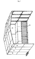
- On
picture 1 there is a possible technical solution of the realization of the invention, without this one being considered a limitation to the protection of the invention. In particular, onpicture 1 there is the extraction wall with the sliding covering open. On this picture indicated as nr. (1) there is the extraction wall consisting of the extraction and filtration system, nr. (2) the aspiration nozzles, nr. (3) the part of the extraction wall that has no role in the aspiration process, and as nr. (4) the sliding covering elements. Onpicture 2 there is the same varnishing cabin in closed position. As we can observe the overall size is considerably reduced. The eventual mobility system is to be seen onpicture 2, the slits indicated as nr. (5). - The pictures represent an efficacious structure suitable for the purpose, and show also a system of support for the sliding elements when in closed position. The existence of such support does not condition the essence of the invention, but may be used as an element of distinction in the claims.
- The number and dimensions of every element of the sliding covering may vary without outranging the invention, such as the form of any element, with particular regards to the constitution of the structure and the angles formed in the edges and if used the form of a hut, at the top. The form of the walls and the covering may be realized also with curve structures without outranging the invention.
Claims (6)
- Movable and extensible tunnel like extraction wall system constituted by an extraction wall on which an aspiration system and a sliding sector covering are installed to be extended in transversal direction respectively to the extraction wall.
- Movable and extensible tunnel like extraction wall system constituted by an extraction wall on which an aspiration system and a sliding sector covering are installed to be extended in transversal direction respectively to the extraction wall and that in closed position find a support fixed to the aspiration wall.
- Movable and extensible tunnel like extraction wall system constituted by an extraction wall on which an aspiration system and a sliding sector covering are installed to be extended in transversal direction respectively to the extraction wall and that in closed position find a support fixed to the aspiration wall, equipped by a device that enables easy mobility of the system.
- Movable and extensible tunnel like extraction wall system constituted by an extraction wall on which an aspiration system and a sliding sector covering are installed to be extended in transversal direction respectively to the extraction wall and that in closed position find a support in a zone fixed to the aspiration wall, equipped with a device for insertion of lifting forks of an elevator that enables easy mobility of the system.
- Movable and extensible tunnel like extraction wall system as in claims 1, 2, 3 and/or 4 to be used as an extraction system for varnishing.
- Movable and extensible tunnel like extraction wall system constituted by an extraction wall on which an aspiration system and a sliding sector covering are installed to be extended in transversal direction respectively to the extraction wall and that in closed position find a support fixed to the aspiration wall equipped with a device for insertion of lifting forks of an elevator that enables easy mobility of the system. All of it as described and represented.
Applications Claiming Priority (1)
| Application Number | Priority Date | Filing Date | Title |
|---|---|---|---|
| IT000011A ITPO20060011A1 (en) | 2006-10-02 | 2006-10-02 | SUCTION WALL WITH SLIDING COVER AND TRANSPORT SYSTEM |
Publications (2)
| Publication Number | Publication Date |
|---|---|
| EP1983118A2 true EP1983118A2 (en) | 2008-10-22 |
| EP1983118A3 EP1983118A3 (en) | 2010-08-25 |
Family
ID=38870593
Family Applications (1)
| Application Number | Title | Priority Date | Filing Date |
|---|---|---|---|
| EP07018692A Withdrawn EP1983118A3 (en) | 2006-10-02 | 2007-09-24 | Transportable and extensible cabin with extraction system |
Country Status (2)
| Country | Link |
|---|---|
| EP (1) | EP1983118A3 (en) |
| IT (1) | ITPO20060011A1 (en) |
Cited By (7)
| Publication number | Priority date | Publication date | Assignee | Title |
|---|---|---|---|---|
| EP1955777B1 (en) * | 2006-11-27 | 2010-09-08 | HPM Divisione Nautica S.r.l. | Containment system for toxic agents deriving from varnishing processes, resin application and similar processes constituted by an extensible tunnel equipped with an aspiration and filtration system |
| WO2012068611A1 (en) * | 2010-11-05 | 2012-05-31 | Dale Andrew Collison | Booth |
| WO2012146366A1 (en) * | 2011-04-26 | 2012-11-01 | Ppg Industries Ohio, Inc. | Paint mixing room |
| US20150298183A1 (en) * | 2012-07-03 | 2015-10-22 | G.A.P. S.P.A. | Mobile plant for aspiration and treatment of fumes and/or dust and/or gaseous mixtures |
| GB2606422A (en) * | 2020-10-26 | 2022-11-09 | John Utting David | Transportable modules and/or vehicle enclosures |
| PL441871A1 (en) * | 2022-07-28 | 2024-01-29 | Mikołajczyk Wiesław Firma Handlowo - Produkcyjno - Usługowa Paco | Mobile foldable building structure with retractable walls and method for extending and connecting the walls of a mobile foldable building structure |
| EP4592466A1 (en) | 2024-01-26 | 2025-07-30 | Modeagroup Spolka z ograniczona odpowiedzialnoscia | A mobile foldable building with extendable walls and a method of extending and connecting the walls of a mobile foldable building |
Family Cites Families (3)
| Publication number | Priority date | Publication date | Assignee | Title |
|---|---|---|---|---|
| FR2623550A1 (en) * | 1987-11-23 | 1989-05-26 | Polygone Expo | Removable modular covered passage |
| AT400532B (en) * | 1994-02-10 | 1996-01-25 | Hueppe Hans Otto Dr | Apparatus for the construction of mobile painting plants or the like |
| DE4405781A1 (en) * | 1994-02-23 | 1995-08-24 | Algema Gmbh Fahrzeug Und Masch | Mobile shelter hut of telescopic construction |
-
2006
- 2006-10-02 IT IT000011A patent/ITPO20060011A1/en unknown
-
2007
- 2007-09-24 EP EP07018692A patent/EP1983118A3/en not_active Withdrawn
Cited By (12)
| Publication number | Priority date | Publication date | Assignee | Title |
|---|---|---|---|---|
| EP1955777B1 (en) * | 2006-11-27 | 2010-09-08 | HPM Divisione Nautica S.r.l. | Containment system for toxic agents deriving from varnishing processes, resin application and similar processes constituted by an extensible tunnel equipped with an aspiration and filtration system |
| WO2012068611A1 (en) * | 2010-11-05 | 2012-05-31 | Dale Andrew Collison | Booth |
| WO2012146366A1 (en) * | 2011-04-26 | 2012-11-01 | Ppg Industries Ohio, Inc. | Paint mixing room |
| US9038321B2 (en) | 2011-04-26 | 2015-05-26 | Ppg Industries Ohio, Inc. | Paint mixing room |
| EP3173549A1 (en) * | 2011-04-26 | 2017-05-31 | PPG Industries Ohio, Inc. | Paint mixing room |
| EP3495585A1 (en) * | 2011-04-26 | 2019-06-12 | PPG Industries Ohio, Inc. | Portable paint mixing room |
| US20150298183A1 (en) * | 2012-07-03 | 2015-10-22 | G.A.P. S.P.A. | Mobile plant for aspiration and treatment of fumes and/or dust and/or gaseous mixtures |
| US10124376B2 (en) * | 2012-07-03 | 2018-11-13 | G.A.P. S.P.A. | Mobile plant for aspiration and treatment of fumes and/or dust and/or gaseous mixtures |
| GB2606422A (en) * | 2020-10-26 | 2022-11-09 | John Utting David | Transportable modules and/or vehicle enclosures |
| GB2606422B (en) * | 2020-10-26 | 2023-11-01 | John Utting David | Transportable modules and/or vehicle enclosures |
| PL441871A1 (en) * | 2022-07-28 | 2024-01-29 | Mikołajczyk Wiesław Firma Handlowo - Produkcyjno - Usługowa Paco | Mobile foldable building structure with retractable walls and method for extending and connecting the walls of a mobile foldable building structure |
| EP4592466A1 (en) | 2024-01-26 | 2025-07-30 | Modeagroup Spolka z ograniczona odpowiedzialnoscia | A mobile foldable building with extendable walls and a method of extending and connecting the walls of a mobile foldable building |
Also Published As
| Publication number | Publication date |
|---|---|
| ITPO20060011A1 (en) | 2008-04-03 |
| EP1983118A3 (en) | 2010-08-25 |
Similar Documents
| Publication | Publication Date | Title |
|---|---|---|
| EP1983118A2 (en) | Transportable and extensible cabin with extraction system | |
| EP3215278B1 (en) | Spray booth ventilation | |
| US10639686B2 (en) | Flow cabinet system for cleaning at least one object | |
| JP5416666B2 (en) | Safety cabinet | |
| EP2874925B1 (en) | Gripper head for transporting parcelled goods packages | |
| US6143048A (en) | Portable air pollution capture apparatus with painting tray | |
| CN105744710A (en) | Dust-removing electrostatic-eliminating equipment | |
| EP1955777B1 (en) | Containment system for toxic agents deriving from varnishing processes, resin application and similar processes constituted by an extensible tunnel equipped with an aspiration and filtration system | |
| US7614841B2 (en) | Lifting fork | |
| JP2010149067A (en) | Hood structure for preventing scattering of coating mist | |
| RU2006132724A (en) | METAL PRODUCT MOVING DEVICE | |
| EP3228581A1 (en) | Improved basket for aerial platform of the like | |
| US20130012103A1 (en) | Mobile cleaning and blasting cubicle | |
| KR20220102393A (en) | Foldable robot painting device | |
| JP4653279B2 (en) | Powder inspection equipment | |
| US6264711B1 (en) | Capture of liquid sanding dust atomized overspray blast media and other errant particles in an unenclosed area | |
| US20160107185A1 (en) | Attachment for a spraying device for use in small places with evacuation of particulates | |
| US20160058254A1 (en) | Exhaust Turbulence Attenuator for Industrial and Shop Vacuum Cleaning Units | |
| DE102013016598B4 (en) | Clean room transport container with chassis | |
| JP4551986B2 (en) | Push-pull ventilator | |
| CN109876940A (en) | A kind of electrostatic sprayer suitable for bend pipe spraying | |
| GB2532047A (en) | Ovens for industrial processes | |
| EP2896892A1 (en) | Extractor hood integrated in a hob | |
| US20030196295A1 (en) | Method and apparatus for dusting | |
| US20190256331A1 (en) | Wheeled cabinet mounted crane |
Legal Events
| Date | Code | Title | Description |
|---|---|---|---|
| PUAI | Public reference made under article 153(3) epc to a published international application that has entered the european phase |
Free format text: ORIGINAL CODE: 0009012 |
|
| AK | Designated contracting states |
Kind code of ref document: A2 Designated state(s): AT BE BG CH CY CZ DE DK EE ES FI FR GB GR HU IE IS IT LI LT LU LV MC MT NL PL PT RO SE SI SK TR |
|
| AX | Request for extension of the european patent |
Extension state: AL BA HR MK RS |
|
| PUAL | Search report despatched |
Free format text: ORIGINAL CODE: 0009013 |
|
| AK | Designated contracting states |
Kind code of ref document: A3 Designated state(s): AT BE BG CH CY CZ DE DK EE ES FI FR GB GR HU IE IS IT LI LT LU LV MC MT NL PL PT RO SE SI SK TR |
|
| AX | Request for extension of the european patent |
Extension state: AL BA HR MK RS |
|
| RIC1 | Information provided on ipc code assigned before grant |
Ipc: B05B 15/12 20060101ALI20100721BHEP Ipc: E04B 1/343 20060101AFI20080111BHEP |
|
| AKY | No designation fees paid | ||
| REG | Reference to a national code |
Ref country code: DE Ref legal event code: R108 Effective date: 20110405 Ref country code: DE Ref legal event code: 8566 |
|
| STAA | Information on the status of an ep patent application or granted ep patent |
Free format text: STATUS: THE APPLICATION IS DEEMED TO BE WITHDRAWN |
|
| 18D | Application deemed to be withdrawn |
Effective date: 20110226 |