EP1983114A2 - Arbeitszubehör, das an ein Ende eines Auslegers einer mobilen Arbeitsmaschine montiert wird. - Google Patents
Arbeitszubehör, das an ein Ende eines Auslegers einer mobilen Arbeitsmaschine montiert wird. Download PDFInfo
- Publication number
- EP1983114A2 EP1983114A2 EP08290346A EP08290346A EP1983114A2 EP 1983114 A2 EP1983114 A2 EP 1983114A2 EP 08290346 A EP08290346 A EP 08290346A EP 08290346 A EP08290346 A EP 08290346A EP 1983114 A2 EP1983114 A2 EP 1983114A2
- Authority
- EP
- European Patent Office
- Prior art keywords
- jaws
- mounting
- coupling block
- spreader
- axes
- Prior art date
- Legal status (The legal status is an assumption and is not a legal conclusion. Google has not performed a legal analysis and makes no representation as to the accuracy of the status listed.)
- Granted
Links
- 230000008878 coupling Effects 0.000 claims abstract description 36
- 238000010168 coupling process Methods 0.000 claims abstract description 36
- 238000005859 coupling reaction Methods 0.000 claims abstract description 36
- 238000003032 molecular docking Methods 0.000 claims description 8
- 230000000712 assembly Effects 0.000 abstract 2
- 238000000429 assembly Methods 0.000 abstract 2
- 238000010008 shearing Methods 0.000 description 7
- 238000004064 recycling Methods 0.000 description 6
- 239000003923 scrap metal Substances 0.000 description 3
- 238000006073 displacement reaction Methods 0.000 description 2
- 239000002184 metal Substances 0.000 description 2
- 241000287107 Passer Species 0.000 description 1
- 241000920340 Pion Species 0.000 description 1
- 229910000831 Steel Inorganic materials 0.000 description 1
- 238000012423 maintenance Methods 0.000 description 1
- 230000004048 modification Effects 0.000 description 1
- 238000012986 modification Methods 0.000 description 1
- 239000010959 steel Substances 0.000 description 1
Images

Classifications
-
- E—FIXED CONSTRUCTIONS
- E02—HYDRAULIC ENGINEERING; FOUNDATIONS; SOIL SHIFTING
- E02F—DREDGING; SOIL-SHIFTING
- E02F3/00—Dredgers; Soil-shifting machines
- E02F3/04—Dredgers; Soil-shifting machines mechanically-driven
- E02F3/28—Dredgers; Soil-shifting machines mechanically-driven with digging tools mounted on a dipper- or bucket-arm, i.e. there is either one arm or a pair of arms, e.g. dippers, buckets
- E02F3/36—Component parts
- E02F3/3604—Devices to connect tools to arms, booms or the like
- E02F3/3609—Devices to connect tools to arms, booms or the like of the quick acting type, e.g. controlled from the operator seat
- E02F3/3636—Devices to connect tools to arms, booms or the like of the quick acting type, e.g. controlled from the operator seat using two or four movable transversal pins
-
- E—FIXED CONSTRUCTIONS
- E02—HYDRAULIC ENGINEERING; FOUNDATIONS; SOIL SHIFTING
- E02F—DREDGING; SOIL-SHIFTING
- E02F3/00—Dredgers; Soil-shifting machines
- E02F3/04—Dredgers; Soil-shifting machines mechanically-driven
- E02F3/28—Dredgers; Soil-shifting machines mechanically-driven with digging tools mounted on a dipper- or bucket-arm, i.e. there is either one arm or a pair of arms, e.g. dippers, buckets
- E02F3/36—Component parts
- E02F3/3604—Devices to connect tools to arms, booms or the like
-
- E—FIXED CONSTRUCTIONS
- E02—HYDRAULIC ENGINEERING; FOUNDATIONS; SOIL SHIFTING
- E02F—DREDGING; SOIL-SHIFTING
- E02F3/00—Dredgers; Soil-shifting machines
- E02F3/04—Dredgers; Soil-shifting machines mechanically-driven
- E02F3/96—Dredgers; Soil-shifting machines mechanically-driven with arrangements for alternate or simultaneous use of different digging elements
- E02F3/965—Dredgers; Soil-shifting machines mechanically-driven with arrangements for alternate or simultaneous use of different digging elements of metal-cutting or concrete-crushing implements
Definitions
- the invention relates to a work accessory device intended to be mounted at the end of the self-propelled machine boom.
- excavating machines including an arrow and an end jack are used to receive various work accessories.
- a hydraulic excavator can be equipped with shears for shearing steel girders, or grinders or concrete crushers, or heavy shears for logs and planks, or other heavy and mobile shearing and recycling accessories. or demolition.
- All these heavy accessories generally comprise at least one movable jaw intended to cooperate with a fixed part or another movable jaw.
- this movable jaw In the case of at least one movable jaw, this movable jaw is pivotally mounted about a major axis of articulation having a large section.
- the change of this jaw for maintenance or replacement currently requires disassembly of this main axis of articulation, which has a significant weight, requiring the intervention of at least two people.
- working accessories comprising movable or cooperating jaws secured to one another.
- These working accessories comprising movable or cooperating jaws secured to each other are previously positioned on supports or support frames, from which it is possible to assemble, dismantle or replace an accessory using a machine. self propelled equipped with boom end of a work attachment mounting device.
- the document FR 2822482 describes such a work accessory mounting device at the end of the self-propelled machine boom.
- This device comprises a connection portion to said boom and a mounting portion of the work accessory.
- the part of mounting of the work accessory comprises at least one actuating cylinder of the work accessory and mechanical mounting means of the work accessory.
- the mechanical mounting means comprise at least two retractable axes between an accessory release position corresponding to the approximation of the axes and an accessory securing position corresponding to the spacing of the axes, so as to leave the axes in place on the device when assembling and dismantling separate work accessories.
- the mechanical mounting means comprise four retractable axes between a close position of accessory release and a remote securing position of an accessory and are associated with actuators of their displacement.
- Each retractable axis displacement actuating member may be a screw accessible from the outside of the device and from the outside of an accessory mounted on the device.
- the device comprises at least one accessory engagement chamfer, as well as means for abutment and accessory positioning, so as to position the accessory in a position close to its position of attachment to the device before proceeding to the device. spacing of the axes of the device to ensure the attachment of the accessory device.
- These abutment and positioning means comprise at least one positioning axis and at least one plane contact abutment.
- a first object of the invention is to overcome the disadvantages of the known art, by providing new devices, in particular new devices constituting working accessories and having movable or cooperating jaws secured to each other, allowing the use of a single actuating cylinder.
- a second object of the invention is to allow a quick and accurate positioning of new devices constituting working accessories and having movable or cooperating jaws secured together, at the end of the excavator machine boom or other self-propelled machine, allowing a change Jaws easy, fast and achievable by one man, usually by the driver of the excavator carrying the tool.
- a third object of the invention is to reduce the operating cost of the demolition and / or recycling sites, by providing new devices, in particular new devices forming work accessories and having movable or cooperating jaws secured to each other. , more economical than the accessories described in the document FR 2822482 .
- the invention relates to a work accessory device intended to be mounted at the end of a self-propelled machine boom having a set of jaws articulated and movable between an open release position and a closed working position, and a lifting beam of mounting carrying two mounting means characterized in that the mounting means comprise hollow tubular shafts passing through openings in said jaws.
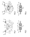
- a first embodiment of work accessory device corresponds to a concrete shear function, especially for cutting concrete during demolition or recycling sites.
- This first embodiment of a work accessory device comprises a first jaw 1, a second jaw 2, and a rudder 3.
- the device comprises two hollow shafts 4 and 5 for securing the jaws 1 and 2 to the spreader 3, thus forming a set of jaws 1 and 2 integral with the spreader 3.
- the jaws 1 and 2 are for example male jaws housed in two female yokes 3a and 3b of the rudder 3.
- the male jaws 1 and 2 are secured to the rudder 3 only by the tubular axes 4 and 5.
- the tubular axes 4 and 5 also constitute the axes of rotation of the jaws 1 and 2 with respect to the spreader 3, and are preferably mounted tightly in the spreader 3.
- Each jaw 1 or 2 has an outgrowth allowing the mounting of a connecting pin to a jack not shown.
- each outgrowth comprises a passage 1a or 2a for a cylinder clevis pin not shown.
- Said protuberances of the jaws of a set of jaws are formed on either side of a space allowing the mounting of a single actuating cylinder between the passages 1a and 2a of said excrescences
- the lifter 3 may further comprise at least one positioning means, and preferably two positioning means 3c and 3d.
- the lifter 3 may finally comprise at least one docking surface, and preferably two docking surfaces 3e and 3f.
- a second embodiment of a work accessory device corresponds to a shearing function of scrap, in particular for cutting scrap metal during demolition or recycling sites.
- This second embodiment of a work accessory device comprises a first jaw 11, a second jaw 12, and a rudder 13.
- the device comprises an axis 6 of articulation and connection of the jaws 11 and 12 to the rudder 13, thus forming a set of jaws 11 and 12 integral with the rudder 13.
- the lifter 3 comprises two hollow tubular shafts 4 and 5 mounted tightly in the spreader 3, said axes 4 and 5 passing through bean-shaped holes cut into the jaws 11 and 12 thus allowing their movement around the axis 6 .
- the male jaws 11 and 12 are secured to the lifter 13 only by an axis 6 of articulation and securing.
- the tubular shafts 4 and 5 are preferably mounted tightly in the crossbar 13.
- Each jaw 11 or 12 has an outgrowth allowing the mounting of a connecting pin to a not shown cylinder.
- each outgrowth includes a passage 11a or 12a for a cylinder clevis pin not shown.
- Said protrusions of the jaws of a set of jaws are formed on either side of a space allowing the mounting of a single actuating cylinder between said protrusions
- the lifter 13 may further comprise at least one positioning means, and preferably two positioning means 13c and 13d.
- the lifter 13 may finally comprise at least one docking surface, and preferably two docking surfaces 13e and 13f.
- a coupling block is intended to be equipped with a device according to the invention not shown.
- the coupling block comprises an upper portion 14 and a lower portion 15.
- the first part or upper part 14 is a connecting part to a self-propelled machine boom not shown and comprises, in a manner known per se, two passages 16 and 17 for mounting pins for attachment to the boom and to the main boom cylinder. the self-propelled machine not shown.
- the lower part 15 can be mounted with possibility of rotation relative to the upper part 14, in a manner known per se.
- the upper portion 14 may comprise a hydraulic motor driving in rotation about the vertical main axis of the device.
- the jack 18 for actuating a device according to the invention forming a working accessory is preferably supplied by means of rotating hydraulic seals.
- the actuating jack 18 is mounted on the device according to the invention by means of pins intended to be mounted in two bores 18a and 19a and has for this purpose end-shaped ends 18b and 19b intended to cooperate with passages 1a and 2a or 11a and 12a of the jaws 1 and 2 or 11 and 12.
- the coupling block comprises abutment means 20, and at least one positioning means 21.
- the coupling block finally comprises two bores 24 and 25 coupling a device according to the invention not shown.
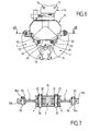
- a coupling block is equipped with a first embodiment of a work accessory device according to the invention described with reference to the figure 1 .
- the coupling of a first embodiment of a work accessory device according to the invention is carried out by vertically lowering the coupling block on the device according to the invention deposited in a vertical support.
- the hitch block is positioned during the descent by the two pins 3c and 3d, located on each side of the rudder 3, which engage in the notches 21 on each side of the hitch block.
- the device according to the invention including the set of jaws 1 and 2 is in place.
- These two shafts 22 and 23 are for example supported on one side and threaded on the other, which allows to screw two nuts 30 and 31 on the other side of the coupling block, to ensure the mounting and locking of the device according to the invention to the coupling block.
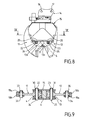
- the demolition apparatus is thus obtained according to the figure 6 , ready to work with jaw set 1 and 2.
- a coupling block is equipped with a second embodiment of a work accessory device according to the invention described with reference to Figures 3 and 4 .
- the coupling of a second embodiment of a work accessory device according to the invention is carried out by vertically lowering the coupling block on the device according to the invention deposited in a vertical support.
- the hitch block is positioned during the descent by the two pins 13c and 13d, located on each side of the rudder 13, which engage in the notches 21 on each side of the hitch block.
- the device according to the invention including the set of jaws 11 and 12 is in place.
- These two shafts 22 and 23 are for example supported on one side and threaded on the other, which allows to screw two nuts 30 and 31 on the other side of the coupling block, to ensure the mounting and locking of the device according to the invention to the coupling block.
- the demolition apparatus is thus obtained according to the figure 8 , ready to work with jaw set 11 and 12.
- disassembly is performed by performing the reverse operations, then reassembly by performing the operations described in reference to Figures 6 to 9 .
- the invention allows a quick and easy assembly and disassembly of a work accessory device according to the invention.
- the assembly and disassembly is done quickly and ergonomically, in a quarter of an hour.
- the assembly and disassembly require the intervention of only one easy operator, using a single key to unscrew the nuts, in the case of nuts of the same dimensions.
Landscapes
- Engineering & Computer Science (AREA)
- Mechanical Engineering (AREA)
- Structural Engineering (AREA)
- Mining & Mineral Resources (AREA)
- Civil Engineering (AREA)
- General Engineering & Computer Science (AREA)
- Crushing And Grinding (AREA)
- Forklifts And Lifting Vehicles (AREA)
- Shovels (AREA)
- Agricultural Machines (AREA)
- Jib Cranes (AREA)
- Working Measures On Existing Buildindgs (AREA)
Applications Claiming Priority (1)
| Application Number | Priority Date | Filing Date | Title |
|---|---|---|---|
| FR0702909A FR2915216B1 (fr) | 2007-04-20 | 2007-04-20 | Dispositif formant accessoire de travail destine a etre monte en extremite de fleche de machine automotrice. |
Publications (3)
| Publication Number | Publication Date |
|---|---|
| EP1983114A2 true EP1983114A2 (de) | 2008-10-22 |
| EP1983114A3 EP1983114A3 (de) | 2010-01-27 |
| EP1983114B1 EP1983114B1 (de) | 2011-02-16 |
Family
ID=38713462
Family Applications (1)
| Application Number | Title | Priority Date | Filing Date |
|---|---|---|---|
| EP08290346A Not-in-force EP1983114B1 (de) | 2007-04-20 | 2008-04-09 | Arbeitszubehör, das an ein Ende eines Auslegers einer mobilen Arbeitsmaschine montiert wird |
Country Status (5)
| Country | Link |
|---|---|
| EP (1) | EP1983114B1 (de) |
| AT (1) | ATE498743T1 (de) |
| DE (1) | DE602008004941D1 (de) |
| ES (1) | ES2360839T3 (de) |
| FR (1) | FR2915216B1 (de) |
Citations (1)
| Publication number | Priority date | Publication date | Assignee | Title |
|---|---|---|---|---|
| FR2822482A1 (fr) | 2001-03-22 | 2002-09-27 | Jean Pierre Dorguin | Dispositif de montage d'accessoires de travail en extremite de fleches de machine automotrice et accessoire de travail correspondant |
Family Cites Families (5)
| Publication number | Priority date | Publication date | Assignee | Title |
|---|---|---|---|---|
| US5044568A (en) * | 1990-08-20 | 1991-09-03 | Takachiho Kogyo Yuugen Kaisha | Hand crusher with rotatably mounted handle |
| JP2555506B2 (ja) * | 1992-03-31 | 1996-11-20 | 大淀ヂ−ゼル株式会社 | 鋼材剪断機 |
| NL9301517A (nl) * | 1993-09-02 | 1995-04-03 | Metholds Hertogenbosch Bv | Inrichting voor het breken en/of knippen van materiaal. |
| DE19506427C1 (de) * | 1995-02-24 | 1996-04-25 | Riepl Josef Gmbh | Zweischalengreifer |
| JP3156754B2 (ja) * | 1996-10-15 | 2001-04-16 | 大淀ヂーゼル株式会社 | 破砕装置 |
-
2007
- 2007-04-20 FR FR0702909A patent/FR2915216B1/fr not_active Expired - Fee Related
-
2008
- 2008-04-09 ES ES08290346T patent/ES2360839T3/es active Active
- 2008-04-09 EP EP08290346A patent/EP1983114B1/de not_active Not-in-force
- 2008-04-09 DE DE602008004941T patent/DE602008004941D1/de active Active
- 2008-04-09 AT AT08290346T patent/ATE498743T1/de not_active IP Right Cessation
Patent Citations (1)
| Publication number | Priority date | Publication date | Assignee | Title |
|---|---|---|---|---|
| FR2822482A1 (fr) | 2001-03-22 | 2002-09-27 | Jean Pierre Dorguin | Dispositif de montage d'accessoires de travail en extremite de fleches de machine automotrice et accessoire de travail correspondant |
Also Published As
| Publication number | Publication date |
|---|---|
| EP1983114B1 (de) | 2011-02-16 |
| ES2360839T3 (es) | 2011-06-09 |
| FR2915216B1 (fr) | 2009-07-03 |
| DE602008004941D1 (de) | 2011-03-31 |
| FR2915216A1 (fr) | 2008-10-24 |
| ATE498743T1 (de) | 2011-03-15 |
| EP1983114A3 (de) | 2010-01-27 |
Similar Documents
| Publication | Publication Date | Title |
|---|---|---|
| FI96527B (fi) | Raskastekoinen murskaustyökalu | |
| EP1218600B1 (de) | Schneid- oder brechwerkzeug | |
| US20040067126A1 (en) | Coupling assembly | |
| FR2914378A1 (fr) | Dispositif et clavette de verrouillage. | |
| EP0629747B1 (de) | Universeller Brecher | |
| FR2822482A1 (fr) | Dispositif de montage d'accessoires de travail en extremite de fleches de machine automotrice et accessoire de travail correspondant | |
| JPH11210013A (ja) | 建設機械の作業具連結装置 | |
| EP1983114B1 (de) | Arbeitszubehör, das an ein Ende eines Auslegers einer mobilen Arbeitsmaschine montiert wird | |
| FR3027037A1 (fr) | Porte-outil pour engin de chantier ou de travaux publics | |
| US5347880A (en) | Method and apparatus for servicing a gear assembly | |
| EP1844199A1 (de) | Schnellkupplungsvorrichtung für ein arbeitswerkzeug | |
| BE1004775A6 (fr) | Broyeur mobile lourd de dalles de beton. | |
| JP2005351075A (ja) | ブーム取付け用の解体作業装置 | |
| KR100814475B1 (ko) | 건설장비용 핀 결합구조 | |
| CA2094579C (en) | Apparatus for mounting gear segments | |
| BE1004776A7 (fr) | Outil mobile lourd de demolition. | |
| EP3004469B1 (de) | Schnellkupplung zum anschluss eines werkzeugs an einer maschine | |
| JPH07150586A (ja) | 作業機具の取付け装置 | |
| JP3196587U (ja) | 油圧ショベルのアタッチメント | |
| JPH04134558U (ja) | 作業機具取付装置 | |
| EP2010720B1 (de) | Vorrichtung zur verbindung eines werkzeugs mit dem ausleger einer maschine, wie zum beispiel einem hydraulikbagger | |
| US20040128870A1 (en) | Actuating coupler for heavy machinery peripheral attachments | |
| US20250178103A1 (en) | Jaw Set with Modular Platforms and Interchangeable Segments | |
| EP1582280B1 (de) | Schneidvorrichtung zum Schneiden von Metallen, besonders zum Schneiden von Metallprofilen | |
| JP7130543B2 (ja) | 建設機械及び建設機械の組立方法 |
Legal Events
| Date | Code | Title | Description |
|---|---|---|---|
| PUAI | Public reference made under article 153(3) epc to a published international application that has entered the european phase |
Free format text: ORIGINAL CODE: 0009012 |
|
| AK | Designated contracting states |
Kind code of ref document: A2 Designated state(s): AT BE BG CH CY CZ DE DK EE ES FI FR GB GR HR HU IE IS IT LI LT LU LV MC MT NL NO PL PT RO SE SI SK TR |
|
| AX | Request for extension of the european patent |
Extension state: AL BA MK RS |
|
| PUAL | Search report despatched |
Free format text: ORIGINAL CODE: 0009013 |
|
| AK | Designated contracting states |
Kind code of ref document: A3 Designated state(s): AT BE BG CH CY CZ DE DK EE ES FI FR GB GR HR HU IE IS IT LI LT LU LV MC MT NL NO PL PT RO SE SI SK TR |
|
| AX | Request for extension of the european patent |
Extension state: AL BA MK RS |
|
| 17P | Request for examination filed |
Effective date: 20100701 |
|
| GRAP | Despatch of communication of intention to grant a patent |
Free format text: ORIGINAL CODE: EPIDOSNIGR1 |
|
| AKX | Designation fees paid |
Designated state(s): AT BE BG CH CY CZ DE DK EE ES FI FR GB GR HR HU IE IS IT LI LT LU LV MC MT NL NO PL PT RO SE SI SK TR |
|
| GRAS | Grant fee paid |
Free format text: ORIGINAL CODE: EPIDOSNIGR3 |
|
| GRAA | (expected) grant |
Free format text: ORIGINAL CODE: 0009210 |
|
| AK | Designated contracting states |
Kind code of ref document: B1 Designated state(s): AT BE BG CH CY CZ DE DK EE ES FI FR GB GR HR HU IE IS IT LI LT LU LV MC MT NL NO PL PT RO SE SI SK TR |
|
| REG | Reference to a national code |
Ref country code: GB Ref legal event code: FG4D Free format text: NOT ENGLISH |
|
| REG | Reference to a national code |
Ref country code: CH Ref legal event code: EP |
|
| REG | Reference to a national code |
Ref country code: IE Ref legal event code: FG4D Free format text: LANGUAGE OF EP DOCUMENT: FRENCH |
|
| REF | Corresponds to: |
Ref document number: 602008004941 Country of ref document: DE Date of ref document: 20110331 Kind code of ref document: P |
|
| REG | Reference to a national code |
Ref country code: DE Ref legal event code: R096 Ref document number: 602008004941 Country of ref document: DE Effective date: 20110331 |
|
| REG | Reference to a national code |
Ref country code: NL Ref legal event code: T3 |
|
| REG | Reference to a national code |
Ref country code: ES Ref legal event code: FG2A Ref document number: 2360839 Country of ref document: ES Kind code of ref document: T3 Effective date: 20110609 |
|
| LTIE | Lt: invalidation of european patent or patent extension |
Effective date: 20110216 |
|
| PG25 | Lapsed in a contracting state [announced via postgrant information from national office to epo] |
Ref country code: GR Free format text: LAPSE BECAUSE OF FAILURE TO SUBMIT A TRANSLATION OF THE DESCRIPTION OR TO PAY THE FEE WITHIN THE PRESCRIBED TIME-LIMIT Effective date: 20110517 Ref country code: LV Free format text: LAPSE BECAUSE OF FAILURE TO SUBMIT A TRANSLATION OF THE DESCRIPTION OR TO PAY THE FEE WITHIN THE PRESCRIBED TIME-LIMIT Effective date: 20110216 Ref country code: PT Free format text: LAPSE BECAUSE OF FAILURE TO SUBMIT A TRANSLATION OF THE DESCRIPTION OR TO PAY THE FEE WITHIN THE PRESCRIBED TIME-LIMIT Effective date: 20110616 Ref country code: HR Free format text: LAPSE BECAUSE OF FAILURE TO SUBMIT A TRANSLATION OF THE DESCRIPTION OR TO PAY THE FEE WITHIN THE PRESCRIBED TIME-LIMIT Effective date: 20110216 Ref country code: SE Free format text: LAPSE BECAUSE OF FAILURE TO SUBMIT A TRANSLATION OF THE DESCRIPTION OR TO PAY THE FEE WITHIN THE PRESCRIBED TIME-LIMIT Effective date: 20110216 Ref country code: NO Free format text: LAPSE BECAUSE OF FAILURE TO SUBMIT A TRANSLATION OF THE DESCRIPTION OR TO PAY THE FEE WITHIN THE PRESCRIBED TIME-LIMIT Effective date: 20110516 Ref country code: LT Free format text: LAPSE BECAUSE OF FAILURE TO SUBMIT A TRANSLATION OF THE DESCRIPTION OR TO PAY THE FEE WITHIN THE PRESCRIBED TIME-LIMIT Effective date: 20110216 |
|
| PG25 | Lapsed in a contracting state [announced via postgrant information from national office to epo] |
Ref country code: FI Free format text: LAPSE BECAUSE OF FAILURE TO SUBMIT A TRANSLATION OF THE DESCRIPTION OR TO PAY THE FEE WITHIN THE PRESCRIBED TIME-LIMIT Effective date: 20110216 Ref country code: CY Free format text: LAPSE BECAUSE OF FAILURE TO SUBMIT A TRANSLATION OF THE DESCRIPTION OR TO PAY THE FEE WITHIN THE PRESCRIBED TIME-LIMIT Effective date: 20110216 Ref country code: AT Free format text: LAPSE BECAUSE OF FAILURE TO SUBMIT A TRANSLATION OF THE DESCRIPTION OR TO PAY THE FEE WITHIN THE PRESCRIBED TIME-LIMIT Effective date: 20110216 Ref country code: BG Free format text: LAPSE BECAUSE OF FAILURE TO SUBMIT A TRANSLATION OF THE DESCRIPTION OR TO PAY THE FEE WITHIN THE PRESCRIBED TIME-LIMIT Effective date: 20110516 Ref country code: SI Free format text: LAPSE BECAUSE OF FAILURE TO SUBMIT A TRANSLATION OF THE DESCRIPTION OR TO PAY THE FEE WITHIN THE PRESCRIBED TIME-LIMIT Effective date: 20110216 Ref country code: PL Free format text: LAPSE BECAUSE OF FAILURE TO SUBMIT A TRANSLATION OF THE DESCRIPTION OR TO PAY THE FEE WITHIN THE PRESCRIBED TIME-LIMIT Effective date: 20110216 |
|
| REG | Reference to a national code |
Ref country code: IE Ref legal event code: FD4D |
|
| PG25 | Lapsed in a contracting state [announced via postgrant information from national office to epo] |
Ref country code: IE Free format text: LAPSE BECAUSE OF FAILURE TO SUBMIT A TRANSLATION OF THE DESCRIPTION OR TO PAY THE FEE WITHIN THE PRESCRIBED TIME-LIMIT Effective date: 20110216 Ref country code: DK Free format text: LAPSE BECAUSE OF FAILURE TO SUBMIT A TRANSLATION OF THE DESCRIPTION OR TO PAY THE FEE WITHIN THE PRESCRIBED TIME-LIMIT Effective date: 20110216 Ref country code: EE Free format text: LAPSE BECAUSE OF FAILURE TO SUBMIT A TRANSLATION OF THE DESCRIPTION OR TO PAY THE FEE WITHIN THE PRESCRIBED TIME-LIMIT Effective date: 20110216 |
|
| PG25 | Lapsed in a contracting state [announced via postgrant information from national office to epo] |
Ref country code: RO Free format text: LAPSE BECAUSE OF FAILURE TO SUBMIT A TRANSLATION OF THE DESCRIPTION OR TO PAY THE FEE WITHIN THE PRESCRIBED TIME-LIMIT Effective date: 20110216 Ref country code: MC Free format text: LAPSE BECAUSE OF NON-PAYMENT OF DUE FEES Effective date: 20110430 Ref country code: SK Free format text: LAPSE BECAUSE OF FAILURE TO SUBMIT A TRANSLATION OF THE DESCRIPTION OR TO PAY THE FEE WITHIN THE PRESCRIBED TIME-LIMIT Effective date: 20110216 Ref country code: CZ Free format text: LAPSE BECAUSE OF FAILURE TO SUBMIT A TRANSLATION OF THE DESCRIPTION OR TO PAY THE FEE WITHIN THE PRESCRIBED TIME-LIMIT Effective date: 20110216 |
|
| PLBE | No opposition filed within time limit |
Free format text: ORIGINAL CODE: 0009261 |
|
| STAA | Information on the status of an ep patent application or granted ep patent |
Free format text: STATUS: NO OPPOSITION FILED WITHIN TIME LIMIT |
|
| PG25 | Lapsed in a contracting state [announced via postgrant information from national office to epo] |
Ref country code: MT Free format text: LAPSE BECAUSE OF FAILURE TO SUBMIT A TRANSLATION OF THE DESCRIPTION OR TO PAY THE FEE WITHIN THE PRESCRIBED TIME-LIMIT Effective date: 20110216 |
|
| 26N | No opposition filed |
Effective date: 20111117 |
|
| REG | Reference to a national code |
Ref country code: DE Ref legal event code: R097 Ref document number: 602008004941 Country of ref document: DE Effective date: 20111117 |
|
| REG | Reference to a national code |
Ref country code: CH Ref legal event code: PL |
|
| PG25 | Lapsed in a contracting state [announced via postgrant information from national office to epo] |
Ref country code: CH Free format text: LAPSE BECAUSE OF NON-PAYMENT OF DUE FEES Effective date: 20120430 Ref country code: LI Free format text: LAPSE BECAUSE OF NON-PAYMENT OF DUE FEES Effective date: 20120430 |
|
| PG25 | Lapsed in a contracting state [announced via postgrant information from national office to epo] |
Ref country code: LU Free format text: LAPSE BECAUSE OF NON-PAYMENT OF DUE FEES Effective date: 20110409 |
|
| PG25 | Lapsed in a contracting state [announced via postgrant information from national office to epo] |
Ref country code: IS Free format text: LAPSE BECAUSE OF FAILURE TO SUBMIT A TRANSLATION OF THE DESCRIPTION OR TO PAY THE FEE WITHIN THE PRESCRIBED TIME-LIMIT Effective date: 20110216 |
|
| PG25 | Lapsed in a contracting state [announced via postgrant information from national office to epo] |
Ref country code: TR Free format text: LAPSE BECAUSE OF FAILURE TO SUBMIT A TRANSLATION OF THE DESCRIPTION OR TO PAY THE FEE WITHIN THE PRESCRIBED TIME-LIMIT Effective date: 20110216 |
|
| PG25 | Lapsed in a contracting state [announced via postgrant information from national office to epo] |
Ref country code: HU Free format text: LAPSE BECAUSE OF FAILURE TO SUBMIT A TRANSLATION OF THE DESCRIPTION OR TO PAY THE FEE WITHIN THE PRESCRIBED TIME-LIMIT Effective date: 20110216 |
|
| REG | Reference to a national code |
Ref country code: FR Ref legal event code: PLFP Year of fee payment: 9 |
|
| PGFP | Annual fee paid to national office [announced via postgrant information from national office to epo] |
Ref country code: NL Payment date: 20160420 Year of fee payment: 9 |
|
| PGFP | Annual fee paid to national office [announced via postgrant information from national office to epo] |
Ref country code: ES Payment date: 20160413 Year of fee payment: 9 Ref country code: GB Payment date: 20160421 Year of fee payment: 9 Ref country code: DE Payment date: 20160421 Year of fee payment: 9 |
|
| PGFP | Annual fee paid to national office [announced via postgrant information from national office to epo] |
Ref country code: IT Payment date: 20160427 Year of fee payment: 9 Ref country code: BE Payment date: 20160420 Year of fee payment: 9 |
|
| REG | Reference to a national code |
Ref country code: DE Ref legal event code: R082 Ref document number: 602008004941 Country of ref document: DE |
|
| REG | Reference to a national code |
Ref country code: FR Ref legal event code: PLFP Year of fee payment: 10 |
|
| REG | Reference to a national code |
Ref country code: DE Ref legal event code: R119 Ref document number: 602008004941 Country of ref document: DE |
|
| REG | Reference to a national code |
Ref country code: NL Ref legal event code: MM Effective date: 20170501 |
|
| GBPC | Gb: european patent ceased through non-payment of renewal fee |
Effective date: 20170409 |
|
| PG25 | Lapsed in a contracting state [announced via postgrant information from national office to epo] |
Ref country code: DE Free format text: LAPSE BECAUSE OF NON-PAYMENT OF DUE FEES Effective date: 20171103 Ref country code: NL Free format text: LAPSE BECAUSE OF NON-PAYMENT OF DUE FEES Effective date: 20170501 |
|
| PG25 | Lapsed in a contracting state [announced via postgrant information from national office to epo] |
Ref country code: GB Free format text: LAPSE BECAUSE OF NON-PAYMENT OF DUE FEES Effective date: 20170409 |
|
| REG | Reference to a national code |
Ref country code: BE Ref legal event code: MM Effective date: 20170430 |
|
| REG | Reference to a national code |
Ref country code: FR Ref legal event code: PLFP Year of fee payment: 11 |
|
| PG25 | Lapsed in a contracting state [announced via postgrant information from national office to epo] |
Ref country code: IT Free format text: LAPSE BECAUSE OF NON-PAYMENT OF DUE FEES Effective date: 20170409 Ref country code: BE Free format text: LAPSE BECAUSE OF NON-PAYMENT OF DUE FEES Effective date: 20170430 |
|
| REG | Reference to a national code |
Ref country code: ES Ref legal event code: FD2A Effective date: 20180710 |
|
| PG25 | Lapsed in a contracting state [announced via postgrant information from national office to epo] |
Ref country code: ES Free format text: LAPSE BECAUSE OF NON-PAYMENT OF DUE FEES Effective date: 20170410 |
|
| PGFP | Annual fee paid to national office [announced via postgrant information from national office to epo] |
Ref country code: FR Payment date: 20200420 Year of fee payment: 13 |
|
| PG25 | Lapsed in a contracting state [announced via postgrant information from national office to epo] |
Ref country code: FR Free format text: LAPSE BECAUSE OF NON-PAYMENT OF DUE FEES Effective date: 20210430 |