EP1982523B1 - Digital broadcasting reception apparatus and robust stream decoding method thereof - Google Patents
Digital broadcasting reception apparatus and robust stream decoding method thereof Download PDFInfo
- Publication number
- EP1982523B1 EP1982523B1 EP07708785A EP07708785A EP1982523B1 EP 1982523 B1 EP1982523 B1 EP 1982523B1 EP 07708785 A EP07708785 A EP 07708785A EP 07708785 A EP07708785 A EP 07708785A EP 1982523 B1 EP1982523 B1 EP 1982523B1
- Authority
- EP
- European Patent Office
- Prior art keywords
- stream
- robust
- data stream
- decoder
- additional data
- Prior art date
- Legal status (The legal status is an assumption and is not a legal conclusion. Google has not performed a legal analysis and makes no representation as to the accuracy of the status listed.)
- Not-in-force
Links
- 238000000034 method Methods 0.000 title claims description 26
- 238000012545 processing Methods 0.000 claims description 2
- 230000009977 dual effect Effects 0.000 description 65
- 238000010586 diagram Methods 0.000 description 34
- 230000005540 biological transmission Effects 0.000 description 21
- 238000006243 chemical reaction Methods 0.000 description 6
- 230000006978 adaptation Effects 0.000 description 4
- 238000013461 design Methods 0.000 description 2
- 239000000654 additive Substances 0.000 description 1
- 230000000996 additive effect Effects 0.000 description 1
- 238000012937 correction Methods 0.000 description 1
- 230000000694 effects Effects 0.000 description 1
- 230000008030 elimination Effects 0.000 description 1
- 238000003379 elimination reaction Methods 0.000 description 1
- 238000005562 fading Methods 0.000 description 1
- 238000003780 insertion Methods 0.000 description 1
- 230000037431 insertion Effects 0.000 description 1
- 230000011664 signaling Effects 0.000 description 1
- 230000009897 systematic effect Effects 0.000 description 1
Images

Classifications
-
- H—ELECTRICITY
- H04—ELECTRIC COMMUNICATION TECHNIQUE
- H04N—PICTORIAL COMMUNICATION, e.g. TELEVISION
- H04N21/00—Selective content distribution, e.g. interactive television or video on demand [VOD]
- H04N21/20—Servers specifically adapted for the distribution of content, e.g. VOD servers; Operations thereof
- H04N21/23—Processing of content or additional data; Elementary server operations; Server middleware
- H04N21/236—Assembling of a multiplex stream, e.g. transport stream, by combining a video stream with other content or additional data, e.g. inserting a URL [Uniform Resource Locator] into a video stream, multiplexing software data into a video stream; Remultiplexing of multiplex streams; Insertion of stuffing bits into the multiplex stream, e.g. to obtain a constant bit-rate; Assembling of a packetised elementary stream
- H04N21/2365—Multiplexing of several video streams
-
- H—ELECTRICITY
- H03—ELECTRONIC CIRCUITRY
- H03M—CODING; DECODING; CODE CONVERSION IN GENERAL
- H03M13/00—Coding, decoding or code conversion, for error detection or error correction; Coding theory basic assumptions; Coding bounds; Error probability evaluation methods; Channel models; Simulation or testing of codes
- H03M13/29—Coding, decoding or code conversion, for error detection or error correction; Coding theory basic assumptions; Coding bounds; Error probability evaluation methods; Channel models; Simulation or testing of codes combining two or more codes or code structures, e.g. product codes, generalised product codes, concatenated codes, inner and outer codes
- H03M13/2933—Coding, decoding or code conversion, for error detection or error correction; Coding theory basic assumptions; Coding bounds; Error probability evaluation methods; Channel models; Simulation or testing of codes combining two or more codes or code structures, e.g. product codes, generalised product codes, concatenated codes, inner and outer codes using a block and a convolutional code
- H03M13/2936—Coding, decoding or code conversion, for error detection or error correction; Coding theory basic assumptions; Coding bounds; Error probability evaluation methods; Channel models; Simulation or testing of codes combining two or more codes or code structures, e.g. product codes, generalised product codes, concatenated codes, inner and outer codes using a block and a convolutional code comprising an outer Reed-Solomon code and an inner convolutional code
-
- H—ELECTRICITY
- H03—ELECTRONIC CIRCUITRY
- H03M—CODING; DECODING; CODE CONVERSION IN GENERAL
- H03M13/00—Coding, decoding or code conversion, for error detection or error correction; Coding theory basic assumptions; Coding bounds; Error probability evaluation methods; Channel models; Simulation or testing of codes
- H03M13/29—Coding, decoding or code conversion, for error detection or error correction; Coding theory basic assumptions; Coding bounds; Error probability evaluation methods; Channel models; Simulation or testing of codes combining two or more codes or code structures, e.g. product codes, generalised product codes, concatenated codes, inner and outer codes
- H03M13/2957—Turbo codes and decoding
- H03M13/296—Particular turbo code structure
- H03M13/2972—Serial concatenation using convolutional component codes
-
- H—ELECTRICITY
- H04—ELECTRIC COMMUNICATION TECHNIQUE
- H04L—TRANSMISSION OF DIGITAL INFORMATION, e.g. TELEGRAPHIC COMMUNICATION
- H04L1/00—Arrangements for detecting or preventing errors in the information received
- H04L1/004—Arrangements for detecting or preventing errors in the information received by using forward error control
- H04L1/0041—Arrangements at the transmitter end
-
- H—ELECTRICITY
- H04—ELECTRIC COMMUNICATION TECHNIQUE
- H04L—TRANSMISSION OF DIGITAL INFORMATION, e.g. TELEGRAPHIC COMMUNICATION
- H04L1/00—Arrangements for detecting or preventing errors in the information received
- H04L1/004—Arrangements for detecting or preventing errors in the information received by using forward error control
- H04L1/0045—Arrangements at the receiver end
- H04L1/0047—Decoding adapted to other signal detection operation
- H04L1/005—Iterative decoding, including iteration between signal detection and decoding operation
-
- H—ELECTRICITY
- H04—ELECTRIC COMMUNICATION TECHNIQUE
- H04L—TRANSMISSION OF DIGITAL INFORMATION, e.g. TELEGRAPHIC COMMUNICATION
- H04L1/00—Arrangements for detecting or preventing errors in the information received
- H04L1/004—Arrangements for detecting or preventing errors in the information received by using forward error control
- H04L1/0045—Arrangements at the receiver end
- H04L1/0054—Maximum-likelihood or sequential decoding, e.g. Viterbi, Fano, ZJ algorithms
-
- H—ELECTRICITY
- H04—ELECTRIC COMMUNICATION TECHNIQUE
- H04L—TRANSMISSION OF DIGITAL INFORMATION, e.g. TELEGRAPHIC COMMUNICATION
- H04L1/00—Arrangements for detecting or preventing errors in the information received
- H04L1/004—Arrangements for detecting or preventing errors in the information received by using forward error control
- H04L1/0056—Systems characterized by the type of code used
- H04L1/0057—Block codes
-
- H—ELECTRICITY
- H04—ELECTRIC COMMUNICATION TECHNIQUE
- H04L—TRANSMISSION OF DIGITAL INFORMATION, e.g. TELEGRAPHIC COMMUNICATION
- H04L1/00—Arrangements for detecting or preventing errors in the information received
- H04L1/004—Arrangements for detecting or preventing errors in the information received by using forward error control
- H04L1/0056—Systems characterized by the type of code used
- H04L1/0059—Convolutional codes
-
- H—ELECTRICITY
- H04—ELECTRIC COMMUNICATION TECHNIQUE
- H04L—TRANSMISSION OF DIGITAL INFORMATION, e.g. TELEGRAPHIC COMMUNICATION
- H04L1/00—Arrangements for detecting or preventing errors in the information received
- H04L1/004—Arrangements for detecting or preventing errors in the information received by using forward error control
- H04L1/0056—Systems characterized by the type of code used
- H04L1/0064—Concatenated codes
- H04L1/0065—Serial concatenated codes
-
- H—ELECTRICITY
- H04—ELECTRIC COMMUNICATION TECHNIQUE
- H04L—TRANSMISSION OF DIGITAL INFORMATION, e.g. TELEGRAPHIC COMMUNICATION
- H04L1/00—Arrangements for detecting or preventing errors in the information received
- H04L1/004—Arrangements for detecting or preventing errors in the information received by using forward error control
- H04L1/0056—Systems characterized by the type of code used
- H04L1/007—Unequal error protection
-
- H—ELECTRICITY
- H04—ELECTRIC COMMUNICATION TECHNIQUE
- H04L—TRANSMISSION OF DIGITAL INFORMATION, e.g. TELEGRAPHIC COMMUNICATION
- H04L1/00—Arrangements for detecting or preventing errors in the information received
- H04L1/004—Arrangements for detecting or preventing errors in the information received by using forward error control
- H04L1/0056—Systems characterized by the type of code used
- H04L1/0071—Use of interleaving
-
- H—ELECTRICITY
- H04—ELECTRIC COMMUNICATION TECHNIQUE
- H04N—PICTORIAL COMMUNICATION, e.g. TELEVISION
- H04N21/00—Selective content distribution, e.g. interactive television or video on demand [VOD]
- H04N21/20—Servers specifically adapted for the distribution of content, e.g. VOD servers; Operations thereof
- H04N21/23—Processing of content or additional data; Elementary server operations; Server middleware
- H04N21/234—Processing of video elementary streams, e.g. splicing of video streams or manipulating encoded video stream scene graphs
- H04N21/2343—Processing of video elementary streams, e.g. splicing of video streams or manipulating encoded video stream scene graphs involving reformatting operations of video signals for distribution or compliance with end-user requests or end-user device requirements
- H04N21/23439—Processing of video elementary streams, e.g. splicing of video streams or manipulating encoded video stream scene graphs involving reformatting operations of video signals for distribution or compliance with end-user requests or end-user device requirements for generating different versions
-
- H—ELECTRICITY
- H04—ELECTRIC COMMUNICATION TECHNIQUE
- H04N—PICTORIAL COMMUNICATION, e.g. TELEVISION
- H04N21/00—Selective content distribution, e.g. interactive television or video on demand [VOD]
- H04N21/20—Servers specifically adapted for the distribution of content, e.g. VOD servers; Operations thereof
- H04N21/23—Processing of content or additional data; Elementary server operations; Server middleware
- H04N21/238—Interfacing the downstream path of the transmission network, e.g. adapting the transmission rate of a video stream to network bandwidth; Processing of multiplex streams
- H04N21/2383—Channel coding or modulation of digital bit-stream, e.g. QPSK modulation
-
- H—ELECTRICITY
- H04—ELECTRIC COMMUNICATION TECHNIQUE
- H04N—PICTORIAL COMMUNICATION, e.g. TELEVISION
- H04N21/00—Selective content distribution, e.g. interactive television or video on demand [VOD]
- H04N21/20—Servers specifically adapted for the distribution of content, e.g. VOD servers; Operations thereof
- H04N21/23—Processing of content or additional data; Elementary server operations; Server middleware
- H04N21/238—Interfacing the downstream path of the transmission network, e.g. adapting the transmission rate of a video stream to network bandwidth; Processing of multiplex streams
- H04N21/2389—Multiplex stream processing, e.g. multiplex stream encrypting
-
- H—ELECTRICITY
- H04—ELECTRIC COMMUNICATION TECHNIQUE
- H04N—PICTORIAL COMMUNICATION, e.g. TELEVISION
- H04N21/00—Selective content distribution, e.g. interactive television or video on demand [VOD]
- H04N21/40—Client devices specifically adapted for the reception of or interaction with content, e.g. set-top-box [STB]; Operations thereof
- H04N21/43—Processing of content or additional data, e.g. demultiplexing additional data from a digital video stream; Elementary client operations, e.g. monitoring of home network or synchronising decoder's clock; Client middleware
- H04N21/434—Disassembling of a multiplex stream, e.g. demultiplexing audio and video streams, extraction of additional data from a video stream; Remultiplexing of multiplex streams; Extraction or processing of SI; Disassembling of packetised elementary stream
- H04N21/4347—Demultiplexing of several video streams
-
- H—ELECTRICITY
- H04—ELECTRIC COMMUNICATION TECHNIQUE
- H04N—PICTORIAL COMMUNICATION, e.g. TELEVISION
- H04N21/00—Selective content distribution, e.g. interactive television or video on demand [VOD]
- H04N21/40—Client devices specifically adapted for the reception of or interaction with content, e.g. set-top-box [STB]; Operations thereof
- H04N21/43—Processing of content or additional data, e.g. demultiplexing additional data from a digital video stream; Elementary client operations, e.g. monitoring of home network or synchronising decoder's clock; Client middleware
- H04N21/438—Interfacing the downstream path of the transmission network originating from a server, e.g. retrieving encoded video stream packets from an IP network
- H04N21/4382—Demodulation or channel decoding, e.g. QPSK demodulation
-
- H—ELECTRICITY
- H04—ELECTRIC COMMUNICATION TECHNIQUE
- H04N—PICTORIAL COMMUNICATION, e.g. TELEVISION
- H04N21/00—Selective content distribution, e.g. interactive television or video on demand [VOD]
- H04N21/40—Client devices specifically adapted for the reception of or interaction with content, e.g. set-top-box [STB]; Operations thereof
- H04N21/43—Processing of content or additional data, e.g. demultiplexing additional data from a digital video stream; Elementary client operations, e.g. monitoring of home network or synchronising decoder's clock; Client middleware
- H04N21/438—Interfacing the downstream path of the transmission network originating from a server, e.g. retrieving encoded video stream packets from an IP network
- H04N21/4385—Multiplex stream processing, e.g. multiplex stream decrypting
-
- H—ELECTRICITY
- H04—ELECTRIC COMMUNICATION TECHNIQUE
- H04L—TRANSMISSION OF DIGITAL INFORMATION, e.g. TELEGRAPHIC COMMUNICATION
- H04L1/00—Arrangements for detecting or preventing errors in the information received
- H04L1/004—Arrangements for detecting or preventing errors in the information received by using forward error control
- H04L1/0045—Arrangements at the receiver end
- H04L1/0055—MAP-decoding
-
- H—ELECTRICITY
- H04—ELECTRIC COMMUNICATION TECHNIQUE
- H04L—TRANSMISSION OF DIGITAL INFORMATION, e.g. TELEGRAPHIC COMMUNICATION
- H04L1/00—Arrangements for detecting or preventing errors in the information received
- H04L2001/0092—Error control systems characterised by the topology of the transmission link
- H04L2001/0093—Point-to-multipoint
-
- H—ELECTRICITY
- H04—ELECTRIC COMMUNICATION TECHNIQUE
- H04L—TRANSMISSION OF DIGITAL INFORMATION, e.g. TELEGRAPHIC COMMUNICATION
- H04L1/00—Arrangements for detecting or preventing errors in the information received
- H04L2001/0098—Unequal error protection
Definitions
- aspects of the present invention generally relate to a digital broadcasting reception apparatus and a robust stream decoding method thereof. More particularly, aspects of the present invention relate to a digital broadcasting reception apparatus and robust stream decoding method thereof so as to provide a receiving apparatus of a simple structure.
- the Advanced Television Systems Committee (ATSC) vestigial sideband (VSB) scheme which is a terrestrial digital broadcasting system in U.S.A., is disadvantageous in that its reception performance is not good in a poor channel environment, particularly, in a Doppler fading channel environment.
- ATSC Advanced Television Systems Committee
- VSB vestigial sideband
- the ATSC has accepted new suggestions under preconditions that compatibility with existing receivers is provided, that the existing receivers do not suffer performance depreciation, and that the performance is improved in comparison with the existing receivers in order to enhance the VSB reception performance.
- a dual transport stream scheme enables watching of the existing HD video in a good channel environment and allows for video reception even in a poor channel environment.
- the dual transport stream scheme generates and transmits a dual transport stream with robust data added to normal data of the conventional ATSC VSB so as to successfully operate in a hostile channel environment.
- FIGS. 1 through 4 a conventional dual transport stream transmission and reception system is described that provides good performance by transmitting and receiving a normal stream and a robust stream and exchanging information by the robust stream.
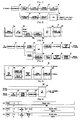
- FIG. 1 is a block diagram of a conventional VSB transmission apparatus
- FIG.2 is a block diagram of a robust processor of FIG. 1 .
- the conventional VSB transmission apparatus includes a randomizer 10, a first RS (Reed Solomon) encoder 11, a first interleaver 12, a robust processor 13, a deinterleaver 14, a second RS encoder 15, a second interleaver 16, a trellis encoder 17, and a multiplexer (MUX) 18.
- RS Random Solomon
- a dual transport stream which is the combination of the normal stream and the robust stream, is constructed at the front end of the randomizer 10.
- the dual transport stream passes through the randomizer 10, the first RS encoder 11, the first interleaver 12, the robust processor 13, the deinterleaver 14, the second RS encoder 15, the second interleaver 16, the trellis encoder 17, and the MUX 18, and then is outputted.
- the robust processor 13 which is responsible for coding the robust stream, follows the first RS encoder 11, the parity added to the dual transport stream at the front end of the randomizer 10 is not correct. Therefore, the deinterleaver 14 is provided after the robust processor 13, and the second RS encoder 15 is provided to modify the incorrect parity. At this time, the first RS encoder 11 only generates a parity space for interleaving without adding the real parity.
- the robust processor 13 includes a symbol interleaver 13a, a normal/robust (N/R) demultiplexer (DE-MUX) 13b, a robust encoder 13c, a robust interleaver 13d, an N/R MUX 13e, and a symbol deinterleaver 13f.
- N/R normal/robust
- DE-MUX demultiplexer
- the dual transport stream interleaved by the first interleaver 12 is converted by the symbol at the symbol interleaver 13a, and is separated to a normal stream and a robust stream at the N/R DE-MUX 13b.
- the normal stream is inputted directly to the N/R MUX 13e.
- the robust stream is processed at the robust encoder 13c and the robust interleaver 13d, and then fed to the N/R MUX 13e.
- the N/R MUX 13e multiplexes the normal stream and the robust stream, and the multiplexed stream is converted by the bit at the symbol deinterleaver 13f for outputting.
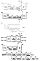
- FIG. 3 is a block diagram of a conventional VSB receiving apparatus
- FIG. 4 is a block diagram of a robust decoder of FIG. 3 .
- the conventional VSB receiving apparatus includes a demodulator 20 for processing the dual transport stream received from the VSB transmission apparatus of FIG. 1 , an equalizer 21, a viterbi decoder 22, a robust decoder 23, a MUX 24, a first deinterleaver 25, an RS decoder 26, a first derandomizer 27, a second deinterleaver 28, a parity eraser 29, a second derandomizer 30, and a robust packet DE-MUX 31.
- the robust decoder 23 of FIG. 3 includes a TCM MAP decoder 23a (TCM refers to trellis code modulation; MAP refers to maximum a posteriori probability.), a robust deinterleaver 23b, a robust MAP decoder 23c, a robust interleaver 23d, a frame formatter 23e, and a symbol deinterleaver 23f.
- TCM trellis code modulation
- MAP refers to maximum a posteriori probability.
- information exchange is conducted through a loop formed between the TCM MAP decoder 23a and the robust MAP decoder 23c until sufficient performance is acquired.
- the data output from the TCM MAP decoder 23a is used for receiving the normal stream, and the frame formatter 23e forwards the data output from the robust MAP decoder 23c to a position corresponding to the robust stream of the normal stream and the robust stream. In doing so, the empty position corresponding to the normal stream is outputted via the symbol deinterleaver 23f to be used for the robust stream reception.
- the VSB receiving apparatus of FIG. 4 should be constructed in accordance with the structure of the VSB transmission apparatus of FIG. 3 . As shown, the VSB receiving apparatus has a complicated structure.
- an aspect of the present invention is to provide a receiver of a simple structure for the performance improvement of a robust stream included in a dual transport stream even when additive coding is implemented at various rates.
- a digital broadcasting reception apparatus includes a robust decoder that decodes a robust stream of a dual transport stream wherein a normal stream and the robust stream are combined.
- the robust decoder includes a first decoder that trellis-decodes the robust stream; a robust deinterleaver that deinterleaves the trellis-decoded robust stream; a second decoder that convolution-decodes the deinterleaved robust stream; a robust interleaver that interleaves the convolution-decoded robust stream; and a frame formatter that adds the decoded data of the second decoder to a part that corresponds to a position of the robust stream of a frame where the normal stream and the robust stream are mixed.
- the decoded data of the first decoder may be outputted to be used for the normal stream reception and the decoded data of the second decoder may be provided to the frame formatter.
- the digital broadcasting reception apparatus may further include a symbol deinterleaver that converts the decoded data of the first decoder by the byte; and a symbol interleaver that converts the decoded data of the second decoder by the symbol.
- a robust stream decoding method of a dual transport stream wherein a normal stream and a robust stream are combined at a digital broadcasting reception apparatus includes trellis-decoding the robust stream; deinterleaving the trellis-decoded robust stream; convolution-decoding the deinterleaved robust stream; interleaving the deinterleaved robust stream; and adding the convolution-decoded data to a part that corresponds to a position of the robust stream of a frame where the normal stream and the robust stream are mixed.
- the trellis-decoded data may be outputted to be used for the normal stream reception, and the convolution-decoded data may be added to a part corresponding to a position of the robust stream.
- the robust stream decoding method may further include converting the trellis-decoded data by the byte; and converting convolution decoded data by the symbol.
- the digital broadcasting transmission and reception apparatuses and the robust stream coding and decoding methods thereof do not complicate the structure of the receiver even when the additional coding is implemented at various rates to improve the performance of the robust stream included in the dual transport stream.
- the compatibility with the existing transmission and reception apparatuses are enabled.
- FIG. 1 is a block diagram of a conventional VSB transmission apparatus
- FIG. 2 is a block diagram of a robust processor of FIG. 1 ;
- FIG. 3 is a block diagram of a conventional VSB reception apparatus
- FIG. 4 is a block diagram of a robust decoder of FIG. 3 ;
- FIG. 5 is a block diagram of a TS constructor which is applied to the present invention.
- FIGS. 6 and 7 are diagrams showing a format of a dual transport stream
- FIGS. 8 and 9 are diagrams showing another format of the dual transport stream
- FIG. 10 is a block diagram of a digital broadcasting transmission apparatus which receives the dual transport stream of FIG. 6 or FIG. 7 ;
- FIG. 11 is a block diagram of a digital broadcasting transmission apparatus which receives the dual transport stream of FIG. 8 or FIG. 9 ;
- FIG. 12 is a block diagram of a robust processor according to one embodiment of the present invention.
- FIG. 13 is a block diagram of a robust processor according to another embodiment of the present invention.
- FIG. 14 is a diagram showing a robust encoder of FIG. 12 and FIG. 13 ;
- FIG. 15 is a block diagram of a symbol deinterleaver of FIG. 12 and FIG. 13 ;
- FIG. 16 is a block diagram of a robust processor according to another embodiment of the present invention.
- FIG. 17 is a block diagram of a digital broadcasting receiving apparatus which is applied to the present invention.
- FIG. 18 is a block diagram of a robust decoder according to one embodiment of the present invention.
- FIG. 19 is a block diagram of a robust decoder according to another embodiment of the present invention.
- FIG. 20 is a flowchart outlining a robust stream coding method according to an embodiment of the present invention.
- FIG. 21 is a flowchart outlining a robust stream decoding method according to an embodiment of the present invention.
- FIG. 5 is a block diagram of a TS constructor.
- a dual transport stream which is applied to aspects of the present invention, is the combination of a normal stream and a robust stream.
- the dual transport stream can be generated at the TS constructor 100 of FIG. 5 .
- the TS constructor 100 includes a Reed-Solomon (RS) encoder 110, a place holder maker 120, an interleaver 130, and a TS MUX 140.
- RS Reed-Solomon
- a normal stream and a robust stream are respectively input to the TS constructor 100.
- the normal stream is input directly to the TS MUX 140, whereas only the robust stream passes through the TS encoder 110, the place holder maker 120, and the interleaver 130 and then is fed to the TS MUX 140.
- Parity is added to the robust stream at the RS encoder 110, and the place holder maker 120 generates an area to which parity is to be inserted by the robust encoder, which will be explained later.
- the robust stream is interleaved at the interleaver 130.
- TS MUX 140 constructs a dual transport stream by multiplexing the normal stream and the robust stream. This method of generating a dual transport stream is well known to persons skilled in the art, and thus the detailed description of the TS constructor 100 will be omitted for brevity.
- FIGS. 6 and 7 are diagrams showing formats of a dual transport stream.
- a MPEG packet consists of a 1-byte sync, a 3-byte header, and a 184-byte payload.
- the header of the MPEG packet includes a packet identifier (PID).
- PID packet identifier
- the type of data contained in the payload part determines whether the MPEG packet is the normal stream or the robust stream.
- Stream (a) of FIG. 6 is an example of the robust stream inputted to the TS constructor 100.
- the payload part contains the robust data.
- the robust data is processed at the RS encoder 110, the placer holder maker 120, and the interleaver 130 of the TS constructor 100 and then fed to the TS MUX 140.
- Stream (b) of FIG. 6 is an example of the normal stream inputted to the TS constructor 100. While the payload part contains the normal data, the stream (b) also includes an adaptation field into which the robust data is inserted by taking account of the combination with the robust stream.
- the adaptation field includes a 2-byte AF header and an N-byte null data space.
- the robust stream (a) of FIG. 6 and the normal stream (b) of FIG. 6 are multiplexed at the TS MUX 140 to thus construct a dual transport stream as shown in stream (c) of FIG. 6 .
- FIG. 7 shows another combination of the robust stream and the normal stream.
- a whole packet contains either the robust data or the normal data.
- the TS MUX 140 arranges the robust stream and the normal stream in the ratio of 1:3. Although the robust stream and the normal stream are shown as arranged in the ratio of 1:3 by way of example, the arrangement is not limited to this exemplary ratio.
- FIGS. 8 and 9 are diagrams showing another format of the dual transport stream.
- Stream (a) of FIG. 8 is a robust stream
- stream (b) of FIG. 8 is a normal stream including an S-byte stuff byte in the adaptation field.
- the S-byte stuff byte is an area to which a supplementary reference sequence (SRS) will be inserted by an SRS inserter, to be explained.
- the TS MUX 140 constructs a dual transport stream as shown in stream (c) by combining the robust stream (a) and the normal stream (b).
- FIG. 9 shows a combination of the robust stream including the stuff byte and the normal stream in which a whole packet contains either the robust data or the normal data.
- the the robust stream and the normal stream are arranged in the ratio of 1:3 by way of example. It should be noted that the positions of the robust data and the stuff byte may be altered if necessary.
- FIG. 10 is a block diagram of a digital broadcasting transmission apparatus that receives the dual transport stream of FIG. 6 or FIG. 7 .
- the digital broadcasting transmission apparatus includes a randomizer 201, a parity area appender 203, a first interleaver 205, a robust processor 207, a deinterleaver 209, an RS encoder 211, a second interleaver 213, a trellis encoder 215, and a MUX 217.
- the randomizer 201 randomizes the dual transport stream input from the TS constructor 100.
- the dual transport stream fed to the randomizer 201 is formatted as in stream (c) of FIG. 6 or as in FIG. 7 . If an MPEG header is used, the dual transport stream may be 188 bytes. If an MPEG header is not used, the dual transport stream may be 187 bytes.
- the parity area appender 203 adds an area so that the parity can be inserted into the randomized dual transport stream for error correction.
- the parity is inserted to this area at the RS encoder 211, to be explained.
- the first interleaver 205 interleaves the dual transport stream having the appended area for inserting the parity.
- the interleaving serves to change data positions in a frame, rather than to change the data per se.
- the robust processor 207 performs encoding in order to improve the performance of the robust stream included in the interleaved dual transport stream.
- the robust processor 207 will be further explained in reference to FIGS. 12 through 17 .
- the first deinterleaver 209 deinterleaves the dual transport stream processed at the robust processor 207.
- the RS encoder 211 appends parity to the deinterleaved dual transport stream. In doing so, the RS encoder 211 inserts the parity into the area that was added to the dual transport stream by the parity area appender 203.
- the second interleaver 213 interleaves the dual transport stream having the appended parity.
- the trellis encoder 215 performs the trellis encoding to the interleaved dual transport stream.
- the MUX 217 adds a segment sync signal and a field sync signal to the trellis-encoded dual transport stream and multiplexes it.
- the dual transport stream to which the segment sync signal and the field sync signal have been added passes through channel modulation and conversion to a signal of an RF channel band, and then is transmitted.
- FIG. 11 illustrates a digital broadcasting transmission apparatus according to another embodiment of the present invention.
- FIG. 11 is a block diagram of a digital broadcasting transmission apparatus that receives the dual transport stream of FIG. 8 or FIG. 9 .
- the digital broadcasting transmission apparatus includes a randomizer 201, an SRS inserter 202, a parity area appender 203, a first interleaver 205, a robust processor 207, a deinterleaver 209, an RS encoder 211, a second interleaver 213, a compatibility parity generator 214, a trellis encoder 215, and a MUX 217.
- the digital broadcasting transmission apparatus of this embodiment has a structure similar to the digital broadcasting transmission apparatus of FIG. 10 . Therefore, identical reference numerals are used with respect to the like elements.
- the randomizer 201 receives the dual transport stream which includes the stuff byte in the adaptation field as shown in stream (c) of FIG. 8 or as shown in FIG. 9 .
- the SRS inserter 202 inserts an SRS into the stuff byte included in the dual transport stream which has been randomized at the randomizer 201. In doing so, the loss and mixing ratio of the payload due to the SRS can be determined according to the rate of insertion of the AF header and the stuff byte into the dual transport stream.
- the compatibility parity generator 214 generates a compatibility parity based on a packet of the dual transport stream to which the parity is appended by the RS encoder 211 and based on the dual transport stream that is trellis-encoded by the trellis encoder 215.
- the compatibility parity generator 214 provides the generated compatibility parity to the trellis encoder 215.
- the trellis encoder 215 trellis-encodes the dual transport stream that has been interleaved by the second interleaver 213 and provides the trellis-encoded dual transport stream to the compatibility parity generator 214. Afterwards, when the compatibility parity is fed from the compatibility parity generator 214, the trellis encoder 215 appends the compatibility parity to the interleaved dual transport stream and provides it to the MUX 217.
- the MUX 217 adds a segment sync signal and a field sync signal to the dual transport stream to which the compatibility parity has been appended by the trellis encoder 215, multiplexes and outputs the resultant stream.
- FIG. 12 is a block diagram of a robust processor according to one embodiment of the present invention.
- the robust processor 207 includes an N/R DE-MUX 207a, a robust encoder 207b, a robust interleaver 207c, and an N/R MUX 207e.
- the N/R DE-MLTX 207a demultiplexes the dual transport stream that has been interleaved by the first interleaver 205 and thus separates the normal stream and the robust stream.
- the N/R DE-MUX 207a converts the bytewise robust stream into two bits starting from a most significant bit (MSB) to a least significant bit (LSB) in order, and provides the converted two bits to the robust interleaver 207c.
- the N/R DE-MUX 207a provides the normal stream, which is separated through the demultiplexing, to the N/R MUX 207e, and provides the robust stream, which is converted to the symbols, to the robust encoder 207b.
- the robust encoder 207b convolutionally encodes the robust stream fed from the N/R DE-MUX 207a.
- convolution encoding refers to parity appending with respect to the robust stream.
- an encoder of a Recursive Systematic Code (RSC) type can be used as the robust encoder 207b and will be described in further detail in reference to FIG. 14 .
- RSC Recursive Systematic Code
- the robust interleaver 207c interleaves the convolutionally encoded robust stream.
- the N/R MUX 207e outputs a dual transport stream by multiplexing the normal stream fed from the N/R DE-MUX 207a and the robust stream fed from the symbol deinterleaver 207d.
- FIG. 13 is a block diagram of a robust processor according to another embodiment of the present invention. Since the robust processor 207 of FIG. 13 has a similar structure to the robust processors 207 of FIG. 12 and shares the same elements, but with differences as further described herein, the same reference numeral 207 is used herein to identify both the robust processors 207 of Figs. 12 and the robust processor 207 of Fig. 13 . As shown in FIG. 13 , the robust processor 207 includes the same elements as the robust processor 207 of FIG. 12 , in particular, an N/R DE-MUX 207a, a robust encoder 207b, a robust interleaver 207c, and an N/R MUX 207e. The robust processor 207 of FIG. 13 further includes a symbol deinterleaver 207d. The symbol deinterleaver 207d deinterleaves the interleaved robust stream. The symbol deinterleaver will be described in more detail in reference to FIG. 15 .
- FIG. 14 is a diagram showing the robust encoder 207b of FIGs. 12, 13 and 16 .
- the robust encoder 207b operates in association with the place holder maker 120, which has been illustrated in reference to FIG. 5 . For instance, if the place holder maker 120 generates the input data of 7, 6, 5, 4, 3, 2, 1, 0 starting from the MSB to the LSB to the 2-byte data in order of (7, x, 6, x, 5, x, 4, x) and (3, x, 2, x, 1, x, 0, x) for the 1/2 rate coding, the robust encoder 207b receives and codes only the data of 7, 5, 3, 1 of the 2 bits forming one symbol when the input data is converted to 4 symbols in order of (7, 6), (5, 4), (3, 2), (1, 0).
- the generated output of 2 bits may be replaced even in a part having no information.
- the encoder of the RSC type as shown in FIG. 14 is used for the robust encoder 207b, parities are simply replaced in the part having no information since there is no change to the input and the output.
- the place holder maker 120 fills only one bit of 4 successive bits with data having information, and inserts an arbitrary value in the remaining three bits. At this time, of 2 symbols consecutively fed to the robust encoder 207b, only one bit has information. As mentioned earlier, the robust encoder 207b operates with respect to only one bit of the data input, and creates the output of 4 bits to replace a 4-bit part having information or having no information.
- the output resulting from the 1/4 rate may be duplicated.
- the position of the input data may be arbitrary.
- the robust encoder 207b can employ only the agreed data as the input using the data position agreed with the place holder maker 120, and replace all of the 4-bit input by making an output.
- the conventional robust processor 13 includes the symbol deinterleaver 13f in FIG. 2 , since the two-symbol positions generated from the 1-bit input are mixed, the conventional digital broadcasting reception apparatus needs to match the two-symbol position at the design phase.
- the positions of the two symbols can be acquired at any time.
- the design of the digital broadcasting receiving apparatus can be simplified.
- FIG. 15 is a block diagram of the symbol deinterleaver 207d of FIG. 13 .
- the symbol deinterleaver 207d serves to deinterleave the interleaved robust stream.
- the symbol deinterleaver 207d includes an N/R MUX 207d1, a byte/symbol converter 207d2, and an N/R DE-MUX 207d3.
- the output of the robust encoder 207b passes through the robust interleaver 207c, which is used to improve the performance in the information exchange at a robust decoder of a digital broadcasting receiving apparatus, to be explained, and the symbol deinterleaver 207d. Next, the output is inserted into the original position of the robust stream by combining with the normal stream at the N/R MUX 207e and then is outputted.
- the symbol deinterleaver 207d is used to fulfill the simple information exchange by virtue of the N/R MUX 207d1, the byte/symbol converter 207d2, and the N/R DE-MUX 207d3, without having to passing through the conventional byte-to-symbol conversion at the digital broadcasting receiving apparatus.
- the N/R MUX 207d1 multiplexes and combines the normal stream and the robust stream fed to the symbol deinterleaver 207d.
- the byte/symbol converter 207d2 converts the normal stream and the robust stream that are multiplexed at the N/R MUX 207d1, by the byte.
- the N/R DE-MUX 207d3 demultiplexes and separates the normal stream and the robust stream that were converted by the byte at the byte/symbol converter 207d2, and then outputs the separated streams.
- the symbol deinterleaver 13f of the conventional robust processor 13 of FIG. 2 operates with respect to all data of the normal stream and the robust stream, whereas the symbol deinterleaver 207d according to this embodiment of the present invention operates with respect to only the robust stream.
- the symbol deinterleaver 207d can be set to have a different value according to the robust stream position of the input data.
- the symbol deinterleaver 207d is affected by the deinterleaver 209 and the byte-to-symbol conversion, its size is equal to the symbol size transmitted to the robust stream for 52 segments. For instance, the number of robust stream space appearing in 52 segments is 52/4+13.
- FIG. 16 is a block diagram of the robust processor 207 according to another embodiment of the present invention. Since the robust processor 207 of FIG. 16 has a similar structure to the robust processors 207 of FIGs. 12 and 13 and shares the same elements, but with differences as further described herein, the same reference numeral 207 is used herein to identify both the robust processors 207 of Figs. 12 and 13 and the robust processor 207 of Fig. 16 .
- the robust processor 207 as shown in FIG. 13 includes the symbol deinterleaver 207d and the robust interleaver 207c separately, in the robust processor 207 according to the embodiment shown in FIG. 16 , the symbol deinterleaver 207d and the robust interleaver 207d are implemented as a single interleaver 207f.
- the symbol deinterleaver 207d and the robust interleaver 207c operate in the same unit size.
- the symbol deinterleaver 207d and the robust interleaver 207c can be implemented as one interleaver which is an integrated interleaver 207f.
- FIG. 17 is a block diagram of a digital broadcasting receiving apparatus according to an aspect of the present invention.
- the digital broadcasting receiving apparatus includes a demodulator 301, an equalizer 303, a viterbi decoder 305, a first deinterleaver 307, an RS decoder 309, a first derandomizer 311, a robust decoder 313, a second interleaver 315, a parity eraser 317, a second derandomizer 319, and a robust DE-MUX 321.
- the demodulator 301 receives the dual transport stream from the digital broadcasting transmission apparatus of FIG. 10 or FIG. 11 , detects sync according to the sync signal added to the baseband signal, and performs the demodulation.
- the equalizer 303 equalizes the dual transport stream demodulated by the demodulator 301.
- the equalizer 303 can remove the interference of the received symbols by compensating the channel distortion of the dual transport stream due to channel multipath.
- the viterbi decoder 305 corrects errors with respect to the normal stream of the dual transport stream and outputs a symbol packet by decoding the error-corrected symbol.
- the first deinterleaver 307 deinterleaves the normal stream that has been viterbi-decoded by the viterbi decoder 305.
- the RS decoder 309 RS-decodes the normal stream that has been deinterleaved by the first deinterleaver 307.
- the first derandomizer 311 derandomizes and outputs the normal stream that has been RS-decoded by the RS decoder 310.
- the robust decoder 313 decodes the robust stream of the dual transport stream equalized by the equalizer 303.
- the robust decoder 313 will be illustrated in detail in reference to FIGS. 18 and 19 .
- the second interleaver 315 interleaves the robust stream decoded by the robust decoder 313.
- the parity eraser 317 eliminates the parity that was appended to the robust stream interleaved by the second interleaver 315.
- the second derandomizer 319 derandomizes the robust stream from which the parity was eliminated by the parity eraser 317.
- the robust DE-MUX 321 demultiplexes the robust stream that was derandomized by the second derandomizer 319.
- FIG. 18 is a block diagram of a robust decoder according to one embodiment of the present invention.
- the robust decoder 313 includes a first decoder 313a, a robust deinterleaver 313b, a second decoder 313c, a robust interleaver 313d, and a frame formatter 313e.
- the first decoder 313a trellis-decodes the robust stream.
- the robust deinterleaver 313b deinterleaves the robust stream that was trellis-decoded by the first decoder 313a.
- the second decoder 313c convolution-decodes the robust stream deinterleaved by the robust deinterleaver 313b.
- the robust interleaver 313d interleaves the robust stream convolution-decoded by the second decoder 313c.
- the frame formatter 313e adds the decoded data of the second decoder 313c to the part that corresponds to the position of the robust stream in the frame where the normal stream and the robust stream are mixed.
- the decoded data of the first decoder 313a is outputted to be used for the normal stream reception and the decoded data of the second decoder 313c is provided to the frame formatter 313e.
- FIG. 19 is a block diagram of a robust decoder 313 according to another embodiment of the present invention. Because the robust decoder 313 of FIG. 19 has a similar structure to the robust decoder 313 of FIG. 18 and shares the same elements, but with added features as described herein, the same reference numeral 313 is used herein to identify both the robust decoder 313 of Fig. 18 and the robust decoder 313 of Fig. 19 .
- the robust decoder 313 includes a first decoder 313a, a symbol deinterleaver 313f, a robust deinterleaver 313b, a symbol interleaver 313g, a robust interleaver 313d, a second decoder 313c, and a frame formatter 313e.
- the robust decoder 313 is applicable to the digital broadcasting reception apparatus when the digital broadcasting transmission apparatus employs the robust processor 207 of FIG. 16 .
- the decoded data of the first decoder 313a is in a symbol unit. After the decoded data is converted by the byte at the symbol deinterleaver 313f, it is deinterleaved by the robust deinterleaver 313b. The decoded data of the second decoder 313c is in a byte unit. After the decoded data is interleaved by the robust interleaver 313d, it is converted by the symbol by the symbol interleaver 313g.
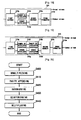
- FIG. 20 is a flowchart outlining a robust stream coding method according to an embodiment of the present invention.
- the robust stream coding method is illustrated in reference to FIGS. 5 through 20 .
- the robust stream coding method at the robust processor 207 as shown in FIGs. 12 and 13 is now illustrated.
- the robust stream coding method at the robust processor 207 as shown in FIG. 16 is similar, except for combining operations S420 and S430.
- the dual transport stream goes through randomization, parity area generation, and interleaving.
- the robust stream included in the dual transport stream is coded at the robust processor 207.
- the N/R DE-MUX 207a separates the normal stream and the robust stream by demultiplexing the dual transport stream.
- the N/R DE-MUX 207a converts the separated robust stream by the symbol, provides the normal stream directly to the N/R MUX 207e, and provides only the robust stream to the robust encoder 207b.
- the robust encoder 207b appends the parity to the robust stream fed from the N/R DE-MUX 207a.
- the robust interleaver 207c interleaves the parity-appended robust stream.
- the symbol deinterleaver 207d deinterleaves the interleaved symbol-wise robust stream. In doing so, the symbol deinterleaver 207d converts and outputs the robust stream by the byte.
- the robust stream separated at the N/R DE-MUX 207a is fed to the N/R MUX 207e.
- the N/R MUX 207e multiplexes the normal stream fed from the N/R DE-MUX 207a and the robust stream fed from the symbol deinterleaver 207d.
- the dual transport stream multiplexed at the N/R MUX 207e is transmitted after passing through deinterleaving, RS encoding, interleaving, trellis encoding, multiplexing, as shown in FIGs. 10 and 11 , and undergoing modulation.
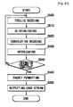
- FIG. 21 is a flowchart outlining a robust stream decoding method according to an embodiment of the present invention.
- the dual transport stream transmitted from the digital broadcasting transmission apparatus is received at the digital broadcasting receiving apparatus as shown in FIG. 17 .
- the dual transport stream goes through demodulation and equalization.
- the robust stream included in the dual transport stream is fed to and decoded at the robust decoder 313.
- the robust stream decoding method at the robust decoder 313 of FIG. 19 will be described.
- the method at the robust decoder 313 of FIG. 18 is similar.
- the robust stream input to the robust decoder 313 is trellis-decoded at the first decoder 313a at operation S500.
- the trellis-decoded robust stream is deinterleaved at the symbol deinterleaver 313f and robust deinterleaver 313b at operation S510.
- the deinterleaved robust stream is convolution-decoded at the second decoder 313c at operation S520.
- the convolution-decoded robust stream is interleaved at the robust interleaver 313d and symbol interleaver 313g at operation S530.
- an information exchange is conducted between the first decoder 313a and the second decoder 313c.
- the frame formatter 313e adds the decoded data of the second decoder 313c to the part corresponding to the position of the robust stream of the frame (packet formatting) at operation S550.
- the first decoder 313a and the frame formatter 313e output the normal stream and the robust stream respectively at operation S560.
- the information exchange continues along the loop formed between the first decoder 313a and the second decoder 313c until the information exchange is completed.
- the process returns according to operation 540-N to operation S500 when the information exchange has not been completed.
- the normal stream passes through deinterleaving, RS decoding, and derandomization and the robust stream passes through deinterleaving, parity elimination, derandomization, and demultiplexing as shown, for example, in FIG. 17 .
Landscapes
- Engineering & Computer Science (AREA)
- Signal Processing (AREA)
- Computer Networks & Wireless Communication (AREA)
- Multimedia (AREA)
- Physics & Mathematics (AREA)
- Probability & Statistics with Applications (AREA)
- Theoretical Computer Science (AREA)
- Artificial Intelligence (AREA)
- Error Detection And Correction (AREA)
- Two-Way Televisions, Distribution Of Moving Picture Or The Like (AREA)
- Detection And Prevention Of Errors In Transmission (AREA)
- Circuits Of Receivers In General (AREA)
Description
- Aspects of the present invention generally relate to a digital broadcasting reception apparatus and a robust stream decoding method thereof. More particularly, aspects of the present invention relate to a digital broadcasting reception apparatus and robust stream decoding method thereof so as to provide a receiving apparatus of a simple structure.
-
US-A1-2004/028076 mentions a robust data extension for 8VSB signaling of the related art which includes a digital broadening reception apparatus and method. The appended claims have been characterized based on this document. - The Advanced Television Systems Committee (ATSC) vestigial sideband (VSB) scheme, which is a terrestrial digital broadcasting system in U.S.A., is disadvantageous in that its reception performance is not good in a poor channel environment, particularly, in a Doppler fading channel environment. Thus, the ATSC has accepted new suggestions under preconditions that compatibility with existing receivers is provided, that the existing receivers do not suffer performance depreciation, and that the performance is improved in comparison with the existing receivers in order to enhance the VSB reception performance.
- Among the suggestions for VSB system improvement, a dual transport stream scheme enables watching of the existing HD video in a good channel environment and allows for video reception even in a poor channel environment. The dual transport stream scheme generates and transmits a dual transport stream with robust data added to normal data of the conventional ATSC VSB so as to successfully operate in a hostile channel environment.
- Hereafter, in reference to
FIGS. 1 through 4 , a conventional dual transport stream transmission and reception system is described that provides good performance by transmitting and receiving a normal stream and a robust stream and exchanging information by the robust stream. -
FIG. 1 is a block diagram of a conventional VSB transmission apparatus, andFIG.2 is a block diagram of a robust processor ofFIG. 1 . - Referring first to
FIG. 1 , the conventional VSB transmission apparatus includes a randomizer 10, a first RS (Reed Solomon) encoder 11, a first interleaver 12, a robust processor 13, a deinterleaver 14, asecond RS encoder 15, asecond interleaver 16, a trellis encoder 17, and a multiplexer (MUX) 18. - Although it is not shown in the drawing, a dual transport stream (TS), which is the combination of the normal stream and the robust stream, is constructed at the front end of the randomizer 10. The dual transport stream passes through the randomizer 10, the first RS encoder 11, the first interleaver 12, the robust processor 13, the deinterleaver 14, the
second RS encoder 15, thesecond interleaver 16, the trellis encoder 17, and the MUX 18, and then is outputted. - Since the robust processor 13, which is responsible for coding the robust stream, follows the first RS encoder 11, the parity added to the dual transport stream at the front end of the randomizer 10 is not correct. Therefore, the deinterleaver 14 is provided after the robust processor 13, and the
second RS encoder 15 is provided to modify the incorrect parity. At this time, the first RS encoder 11 only generates a parity space for interleaving without adding the real parity. - Referring now to
FIG. 2 , the robust processor 13 includes a symbol interleaver 13a, a normal/robust (N/R) demultiplexer (DE-MUX) 13b, arobust encoder 13c, a robust interleaver 13d, an N/R MUX 13e, and a symbol deinterleaver 13f. - The dual transport stream interleaved by the first interleaver 12 is converted by the symbol at the symbol interleaver 13a, and is separated to a normal stream and a robust stream at the N/R DE-MUX 13b. The normal stream is inputted directly to the N/R MUX 13e. The robust stream is processed at the
robust encoder 13c and the robust interleaver 13d, and then fed to the N/R MUX 13e. The N/R MUX 13e multiplexes the normal stream and the robust stream, and the multiplexed stream is converted by the bit at the symbol deinterleaver 13f for outputting. -
FIG. 3 is a block diagram of a conventional VSB receiving apparatus, andFIG. 4 is a block diagram of a robust decoder ofFIG. 3 . - Referring to
FIG. 3 , the conventional VSB receiving apparatus includes a demodulator 20 for processing the dual transport stream received from the VSB transmission apparatus ofFIG. 1 , an equalizer 21, a viterbi decoder 22, arobust decoder 23, a MUX 24, afirst deinterleaver 25, anRS decoder 26, a first derandomizer 27, asecond deinterleaver 28, a parity eraser 29, asecond derandomizer 30, and a robust packet DE-MUX 31. - Referring now to
FIG. 4 , therobust decoder 23 ofFIG. 3 includes a TCM MAP decoder 23a (TCM refers to trellis code modulation; MAP refers to maximum a posteriori probability.), a robust deinterleaver 23b, arobust MAP decoder 23c, a robust interleaver 23d, a frame formatter 23e, and a symbol deinterleaver 23f. - As shown in the drawings, information exchange is conducted through a loop formed between the TCM MAP decoder 23a and the
robust MAP decoder 23c until sufficient performance is acquired. Upon the completion of the information exchange, the data output from the TCM MAP decoder 23a is used for receiving the normal stream, and the frame formatter 23e forwards the data output from therobust MAP decoder 23c to a position corresponding to the robust stream of the normal stream and the robust stream. In doing so, the empty position corresponding to the normal stream is outputted via the symbol deinterleaver 23f to be used for the robust stream reception. - As discussed above, when the conventional VSB transmission and reception apparatuses add the robust coding, such as a 1/4 rate coding, to the robust stream using the
robust encoder 13c, the VSB receiving apparatus ofFIG. 4 should be constructed in accordance with the structure of the VSB transmission apparatus ofFIG. 3 . As shown, the VSB receiving apparatus has a complicated structure. - Aspects of the present invention have been provided to address the above-mentioned and other problems and disadvantages occurring in the conventional arrangement, and an aspect of the present invention is to provide a receiver of a simple structure for the performance improvement of a robust stream included in a dual transport stream even when additive coding is implemented at various rates.
- Additional aspects and/or advantages of the invention will be set forth in part in the description which follows and, in part, will be obvious from the description, or may be learned by practice of the invention.
- In accordance with an aspect of the present invention, a digital broadcasting reception apparatus includes a robust decoder that decodes a robust stream of a dual transport stream wherein a normal stream and the robust stream are combined. The robust decoder includes a first decoder that trellis-decodes the robust stream; a robust deinterleaver that deinterleaves the trellis-decoded robust stream; a second decoder that convolution-decodes the deinterleaved robust stream; a robust interleaver that interleaves the convolution-decoded robust stream; and a frame formatter that adds the decoded data of the second decoder to a part that corresponds to a position of the robust stream of a frame where the normal stream and the robust stream are mixed.
- When information exchange between the first decoder and the second decoder is completed through the robust deinterleaver and the robust interleaver, the decoded data of the first decoder may be outputted to be used for the normal stream reception and the decoded data of the second decoder may be provided to the frame formatter.
- The digital broadcasting reception apparatus may further include a symbol deinterleaver that converts the decoded data of the first decoder by the byte; and a symbol interleaver that converts the decoded data of the second decoder by the symbol.
- In accordance with another aspect of the present invention, a robust stream decoding method of a dual transport stream wherein a normal stream and a robust stream are combined at a digital broadcasting reception apparatus, includes trellis-decoding the robust stream; deinterleaving the trellis-decoded robust stream; convolution-decoding the deinterleaved robust stream; interleaving the deinterleaved robust stream; and adding the convolution-decoded data to a part that corresponds to a position of the robust stream of a frame where the normal stream and the robust stream are mixed.
- The trellis-decoded data may be outputted to be used for the normal stream reception, and the convolution-decoded data may be added to a part corresponding to a position of the robust stream.
- The robust stream decoding method may further include converting the trellis-decoded data by the byte; and converting convolution decoded data by the symbol.
- As set forth, according to an embodiment of the present invention, the digital broadcasting transmission and reception apparatuses and the robust stream coding and decoding methods thereof do not complicate the structure of the receiver even when the additional coding is implemented at various rates to improve the performance of the robust stream included in the dual transport stream. In addition, advantageously, the compatibility with the existing transmission and reception apparatuses are enabled.
- Although a few embodiments of the present invention have been shown and described, it would be appreciated by those skilled in the art that changes may be made in these embodiments without departing from the principles and spirit of the invention, the scope of which is defined in the claims and their equivalents.
- These and/or other aspects and advantages of the invention will become apparent and more readily appreciated from the following description of the embodiments, taken in conjunction with the accompanying drawings of which:
-
FIG. 1 is a block diagram of a conventional VSB transmission apparatus; -
FIG. 2 is a block diagram of a robust processor ofFIG. 1 ; -
FIG. 3 is a block diagram of a conventional VSB reception apparatus; -
FIG. 4 is a block diagram of a robust decoder ofFIG. 3 ; -
FIG. 5 is a block diagram of a TS constructor which is applied to the present invention; -
FIGS. 6 and7 are diagrams showing a format of a dual transport stream; -
FIGS. 8 and 9 are diagrams showing another format of the dual transport stream; -
FIG. 10 is a block diagram of a digital broadcasting transmission apparatus which receives the dual transport stream ofFIG. 6 orFIG. 7 ; -
FIG. 11 is a block diagram of a digital broadcasting transmission apparatus which receives the dual transport stream ofFIG. 8 or FIG. 9 ; -
FIG. 12 is a block diagram of a robust processor according to one embodiment of the present invention; -
FIG. 13 is a block diagram of a robust processor according to another embodiment of the present invention; -
FIG. 14 is a diagram showing a robust encoder ofFIG. 12 and FIG. 13 ; -
FIG. 15 is a block diagram of a symbol deinterleaver ofFIG. 12 and FIG. 13 ; -
FIG. 16 is a block diagram of a robust processor according to another embodiment of the present invention; -
FIG. 17 is a block diagram of a digital broadcasting receiving apparatus which is applied to the present invention; -
FIG. 18 is a block diagram of a robust decoder according to one embodiment of the present invention; -
FIG. 19 is a block diagram of a robust decoder according to another embodiment of the present invention; -
FIG. 20 is a flowchart outlining a robust stream coding method according to an embodiment of the present invention; and -
FIG. 21 is a flowchart outlining a robust stream decoding method according to an embodiment of the present invention. - Reference will now be made in detail to the present embodiments of the present invention, examples of which are illustrated in the accompanying drawings, wherein like reference numerals refer to the like elements throughout. The embodiments are described below in order to explain the present invention by referring to the figures.
-
FIG. 5 is a block diagram of a TS constructor. - A dual transport stream, which is applied to aspects of the present invention, is the combination of a normal stream and a robust stream. The dual transport stream can be generated at the TS constructor 100 of
FIG. 5 . - Referring now to
FIG. 5 , theTS constructor 100 includes a Reed-Solomon (RS) encoder 110, aplace holder maker 120, an interleaver 130, and aTS MUX 140. - A normal stream and a robust stream are respectively input to the
TS constructor 100. At this time, the normal stream is input directly to theTS MUX 140, whereas only the robust stream passes through the TS encoder 110, theplace holder maker 120, and the interleaver 130 and then is fed to theTS MUX 140. - Parity is added to the robust stream at the RS encoder 110, and the
place holder maker 120 generates an area to which parity is to be inserted by the robust encoder, which will be explained later. The robust stream is interleaved at the interleaver 130. Next,TS MUX 140 constructs a dual transport stream by multiplexing the normal stream and the robust stream. This method of generating a dual transport stream is well known to persons skilled in the art, and thus the detailed description of theTS constructor 100 will be omitted for brevity. -
FIGS. 6 and7 are diagrams showing formats of a dual transport stream. - Typically, a MPEG packet consists of a 1-byte sync, a 3-byte header, and a 184-byte payload. The header of the MPEG packet includes a packet identifier (PID). The type of data contained in the payload part determines whether the MPEG packet is the normal stream or the robust stream.
- Stream (a) of
FIG. 6 is an example of the robust stream inputted to theTS constructor 100. The payload part contains the robust data. The robust data is processed at the RS encoder 110, theplacer holder maker 120, and the interleaver 130 of theTS constructor 100 and then fed to theTS MUX 140. - Stream (b) of
FIG. 6 is an example of the normal stream inputted to theTS constructor 100. While the payload part contains the normal data, the stream (b) also includes an adaptation field into which the robust data is inserted by taking account of the combination with the robust stream. The adaptation field includes a 2-byte AF header and an N-byte null data space. - The robust stream (a) of
FIG. 6 and the normal stream (b) ofFIG. 6 are multiplexed at theTS MUX 140 to thus construct a dual transport stream as shown in stream (c) ofFIG. 6 . -
FIG. 7 shows another combination of the robust stream and the normal stream. A whole packet contains either the robust data or the normal data. TheTS MUX 140 arranges the robust stream and the normal stream in the ratio of 1:3. Although the robust stream and the normal stream are shown as arranged in the ratio of 1:3 by way of example, the arrangement is not limited to this exemplary ratio. -
FIGS. 8 and 9 are diagrams showing another format of the dual transport stream. - Stream (a) of
FIG. 8 is a robust stream, and stream (b) ofFIG. 8 is a normal stream including an S-byte stuff byte in the adaptation field. The S-byte stuff byte is an area to which a supplementary reference sequence (SRS) will be inserted by an SRS inserter, to be explained. TheTS MUX 140 constructs a dual transport stream as shown in stream (c) by combining the robust stream (a) and the normal stream (b). -
FIG. 9 shows a combination of the robust stream including the stuff byte and the normal stream in which a whole packet contains either the robust data or the normal data. The the robust stream and the normal stream are arranged in the ratio of 1:3 by way of example. It should be noted that the positions of the robust data and the stuff byte may be altered if necessary. -
FIG. 10 is a block diagram of a digital broadcasting transmission apparatus that receives the dual transport stream ofFIG. 6 orFIG. 7 . In this embodiment of the present invention, the digital broadcasting transmission apparatus includes arandomizer 201, aparity area appender 203, afirst interleaver 205, arobust processor 207, a deinterleaver 209, anRS encoder 211, asecond interleaver 213, atrellis encoder 215, and aMUX 217. - The
randomizer 201 randomizes the dual transport stream input from theTS constructor 100. The dual transport stream fed to therandomizer 201 is formatted as in stream (c) ofFIG. 6 or as inFIG. 7 . If an MPEG header is used, the dual transport stream may be 188 bytes. If an MPEG header is not used, the dual transport stream may be 187 bytes. - The
parity area appender 203 adds an area so that the parity can be inserted into the randomized dual transport stream for error correction. The parity is inserted to this area at theRS encoder 211, to be explained. - The
first interleaver 205 interleaves the dual transport stream having the appended area for inserting the parity. The interleaving serves to change data positions in a frame, rather than to change the data per se. - The
robust processor 207 performs encoding in order to improve the performance of the robust stream included in the interleaved dual transport stream. Therobust processor 207 will be further explained in reference toFIGS. 12 through 17 . - The first deinterleaver 209 deinterleaves the dual transport stream processed at the
robust processor 207. - The
RS encoder 211 appends parity to the deinterleaved dual transport stream. In doing so, theRS encoder 211 inserts the parity into the area that was added to the dual transport stream by theparity area appender 203. - The
second interleaver 213 interleaves the dual transport stream having the appended parity. - The
trellis encoder 215 performs the trellis encoding to the interleaved dual transport stream. - The
MUX 217 adds a segment sync signal and a field sync signal to the trellis-encoded dual transport stream and multiplexes it. Next, although it is not illustrated, the dual transport stream to which the segment sync signal and the field sync signal have been added passes through channel modulation and conversion to a signal of an RF channel band, and then is transmitted. -
FIG. 11 illustrates a digital broadcasting transmission apparatus according to another embodiment of the present invention. In particular,FIG. 11 is a block diagram of a digital broadcasting transmission apparatus that receives the dual transport stream ofFIG. 8 or FIG. 9 . - According to
FIG. 11 , the digital broadcasting transmission apparatus includes arandomizer 201, anSRS inserter 202, aparity area appender 203, afirst interleaver 205, arobust processor 207, a deinterleaver 209, anRS encoder 211, asecond interleaver 213, acompatibility parity generator 214, atrellis encoder 215, and aMUX 217. - The digital broadcasting transmission apparatus of this embodiment has a structure similar to the digital broadcasting transmission apparatus of
FIG. 10 . Therefore, identical reference numerals are used with respect to the like elements. - The
randomizer 201 receives the dual transport stream which includes the stuff byte in the adaptation field as shown in stream (c) ofFIG. 8 or as shown inFIG. 9 . - The
SRS inserter 202 inserts an SRS into the stuff byte included in the dual transport stream which has been randomized at therandomizer 201. In doing so, the loss and mixing ratio of the payload due to the SRS can be determined according to the rate of insertion of the AF header and the stuff byte into the dual transport stream. - The
compatibility parity generator 214 generates a compatibility parity based on a packet of the dual transport stream to which the parity is appended by theRS encoder 211 and based on the dual transport stream that is trellis-encoded by thetrellis encoder 215. Thecompatibility parity generator 214 provides the generated compatibility parity to thetrellis encoder 215. - The
trellis encoder 215 trellis-encodes the dual transport stream that has been interleaved by thesecond interleaver 213 and provides the trellis-encoded dual transport stream to thecompatibility parity generator 214. Afterwards, when the compatibility parity is fed from thecompatibility parity generator 214, thetrellis encoder 215 appends the compatibility parity to the interleaved dual transport stream and provides it to theMUX 217. - The
MUX 217 adds a segment sync signal and a field sync signal to the dual transport stream to which the compatibility parity has been appended by thetrellis encoder 215, multiplexes and outputs the resultant stream. -
FIG. 12 is a block diagram of a robust processor according to one embodiment of the present invention. - As shown in
FIG. 12 , therobust processor 207 according to an embodiment of the present invention includes an N/R DE-MUX 207a, arobust encoder 207b, arobust interleaver 207c, and an N/R MUX 207e. - The N/
R DE-MLTX 207a demultiplexes the dual transport stream that has been interleaved by thefirst interleaver 205 and thus separates the normal stream and the robust stream. Next, the N/R DE-MUX 207a converts the bytewise robust stream into two bits starting from a most significant bit (MSB) to a least significant bit (LSB) in order, and provides the converted two bits to therobust interleaver 207c. - For instance, when 1-byte input, that is, an 8-bit input is numbered from the MSB to the LSB in order, such as 7, 6, 5, 4, 3, 2, 1, 0, the 8-bit input is converted to 4 symbols in the order of (7, 6), (5, 4), (3, 2), and (1, 0).
- Next, the N/
R DE-MUX 207a provides the normal stream, which is separated through the demultiplexing, to the N/R MUX 207e, and provides the robust stream, which is converted to the symbols, to therobust encoder 207b. - The
robust encoder 207b convolutionally encodes the robust stream fed from the N/R DE-MUX 207a. Herein, convolution encoding refers to parity appending with respect to the robust stream. - According to this embodiment of the present invention, an encoder of a Recursive Systematic Code (RSC) type can be used as the
robust encoder 207b and will be described in further detail in reference toFIG. 14 . - The
robust interleaver 207c interleaves the convolutionally encoded robust stream. - The N/
R MUX 207e outputs a dual transport stream by multiplexing the normal stream fed from the N/R DE-MUX 207a and the robust stream fed from thesymbol deinterleaver 207d. -
FIG. 13 is a block diagram of a robust processor according to another embodiment of the present invention. Since therobust processor 207 ofFIG. 13 has a similar structure to therobust processors 207 ofFIG. 12 and shares the same elements, but with differences as further described herein, thesame reference numeral 207 is used herein to identify both therobust processors 207 ofFigs. 12 and therobust processor 207 ofFig. 13 . As shown inFIG. 13 , therobust processor 207 includes the same elements as therobust processor 207 ofFIG. 12 , in particular, an N/R DE-MUX 207a, arobust encoder 207b, arobust interleaver 207c, and an N/R MUX 207e. Therobust processor 207 ofFIG. 13 further includes asymbol deinterleaver 207d. The symbol deinterleaver 207d deinterleaves the interleaved robust stream. The symbol deinterleaver will be described in more detail in reference toFIG. 15 . -
FIG. 14 is a diagram showing therobust encoder 207b ofFIGs. 12, 13 and 16 . - The
robust encoder 207b operates in association with theplace holder maker 120, which has been illustrated in reference toFIG. 5 . For instance, if theplace holder maker 120 generates the input data of 7, 6, 5, 4, 3, 2, 1, 0 starting from the MSB to the LSB to the 2-byte data in order of (7, x, 6, x, 5, x, 4, x) and (3, x, 2, x, 1, x, 0, x) for the 1/2 rate coding, therobust encoder 207b receives and codes only the data of 7, 5, 3, 1 of the 2 bits forming one symbol when the input data is converted to 4 symbols in order of (7, 6), (5, 4), (3, 2), (1, 0). - The generated output of 2 bits may be replaced even in a part having no information. When the encoder of the RSC type as shown in
FIG. 14 is used for therobust encoder 207b, parities are simply replaced in the part having no information since there is no change to the input and the output. - In an embodiment wherein the
robust encoder 207b performs the coding of 1/4 rate, theplace holder maker 120 fills only one bit of 4 successive bits with data having information, and inserts an arbitrary value in the remaining three bits. At this time, of 2 symbols consecutively fed to therobust encoder 207b, only one bit has information. As mentioned earlier, therobust encoder 207b operates with respect to only one bit of the data input, and creates the output of 4 bits to replace a 4-bit part having information or having no information. - For instance, when the
place holder maker 120 outputs (a, x, y, z) with respect to an input 1-bit "a" (x, y, z are arbitrary values having no information), two symbols of (a, x), (y, z) being input in sequence are generated by a byte-to-symbol conversion, which is well-known. Only the data part "a" of the input is received in accordance with the operation of theplace holder maker 120 so as to output 4 bits. The output 4 bits are replaced with theinput 2 symbols of (a, x) and (y, z). - In the embodiment wherein an RSC type encoder as shown in
FIG. 14 (the encoder of 1/2 rate) is used for therobust encoder 207b, the output resulting from the 1/4 rate may be duplicated. - When two symbols of (a, x), (y, z) are received as the input, only "a" is used as the input and (p1, p2) is outputted. When the output (p1, p2) is generated, (a, p), (a, p) may be outputted.
- Of the successive 4-bit output generated for the coding of 1/4 rate at the
place holder maker 120, the position of the input data may be arbitrary. Therobust encoder 207b can employ only the agreed data as the input using the data position agreed with theplace holder maker 120, and replace all of the 4-bit input by making an output. - As illustrated above, when the
place holder maker 120 operates, two successive symbols, which are generated from 1-bit input data using the byte-to-symbol conversion, which groups two bits starting from the MSB to the LSB, are fed to therobust encoder 207. - In other words, if the conventional robust processor 13 includes the symbol deinterleaver 13f in
FIG. 2 , since the two-symbol positions generated from the 1-bit input are mixed, the conventional digital broadcasting reception apparatus needs to match the two-symbol position at the design phase. - However, in the embodiment of the present invention, as the outputted two symbols generated from the data input appear in succession, the positions of the two symbols can be acquired at any time. Thus, the design of the digital broadcasting receiving apparatus can be simplified.
-
FIG. 15 is a block diagram of thesymbol deinterleaver 207d ofFIG. 13 . - The
symbol deinterleaver 207d serves to deinterleave the interleaved robust stream. Thesymbol deinterleaver 207d includes an N/R MUX 207d1, a byte/symbol converter 207d2, and an N/R DE-MUX 207d3. - The output of the
robust encoder 207b passes through therobust interleaver 207c, which is used to improve the performance in the information exchange at a robust decoder of a digital broadcasting receiving apparatus, to be explained, and thesymbol deinterleaver 207d. Next, the output is inserted into the original position of the robust stream by combining with the normal stream at the N/R MUX 207e and then is outputted. - The
symbol deinterleaver 207d is used to fulfill the simple information exchange by virtue of the N/R MUX 207d1, the byte/symbol converter 207d2, and the N/R DE-MUX 207d3, without having to passing through the conventional byte-to-symbol conversion at the digital broadcasting receiving apparatus. - The N/R MUX 207d1 multiplexes and combines the normal stream and the robust stream fed to the
symbol deinterleaver 207d. - The byte/symbol converter 207d2 converts the normal stream and the robust stream that are multiplexed at the N/R MUX 207d1, by the byte.
- The N/R DE-MUX 207d3 demultiplexes and separates the normal stream and the robust stream that were converted by the byte at the byte/symbol converter 207d2, and then outputs the separated streams.
- The symbol deinterleaver 13f of the conventional robust processor 13 of
FIG. 2 operates with respect to all data of the normal stream and the robust stream, whereas thesymbol deinterleaver 207d according to this embodiment of the present invention operates with respect to only the robust stream. In addition, thesymbol deinterleaver 207d can be set to have a different value according to the robust stream position of the input data. - As the
symbol deinterleaver 207d is affected by the deinterleaver 209 and the byte-to-symbol conversion, its size is equal to the symbol size transmitted to the robust stream for 52 segments. For instance, the number of robust stream space appearing in 52 segments is 52/4+13. Herein, by taking account of the conversion of 1 byte to 4 symbols, thesymbol deinterleaver 207d can serve as a 128*4*13=6656 block interleaver. -
FIG. 16 is a block diagram of therobust processor 207 according to another embodiment of the present invention. Since therobust processor 207 ofFIG. 16 has a similar structure to therobust processors 207 ofFIGs. 12 and 13 and shares the same elements, but with differences as further described herein, thesame reference numeral 207 is used herein to identify both therobust processors 207 ofFigs. 12 and 13 and therobust processor 207 ofFig. 16 . - While the
robust processor 207 as shown inFIG. 13 includes thesymbol deinterleaver 207d and therobust interleaver 207c separately, in therobust processor 207 according to the embodiment shown inFIG. 16 , thesymbol deinterleaver 207d and therobust interleaver 207d are implemented as a single interleaver 207f. - In other words, the
symbol deinterleaver 207d and therobust interleaver 207c operate in the same unit size. Thus, as shown inFIG. 16 , thesymbol deinterleaver 207d and therobust interleaver 207c can be implemented as one interleaver which is an integrated interleaver 207f. -
FIG. 17 is a block diagram of a digital broadcasting receiving apparatus according to an aspect of the present invention. - Referring to
FIG. 17 , the digital broadcasting receiving apparatus applied to the present invention, includes ademodulator 301, anequalizer 303, aviterbi decoder 305, a first deinterleaver 307, anRS decoder 309, afirst derandomizer 311, arobust decoder 313, asecond interleaver 315, aparity eraser 317, asecond derandomizer 319, and arobust DE-MUX 321. - The
demodulator 301 receives the dual transport stream from the digital broadcasting transmission apparatus ofFIG. 10 or FIG. 11 , detects sync according to the sync signal added to the baseband signal, and performs the demodulation. - The
equalizer 303 equalizes the dual transport stream demodulated by thedemodulator 301. In more detail, theequalizer 303 can remove the interference of the received symbols by compensating the channel distortion of the dual transport stream due to channel multipath. - The
viterbi decoder 305 corrects errors with respect to the normal stream of the dual transport stream and outputs a symbol packet by decoding the error-corrected symbol. - The first deinterleaver 307 deinterleaves the normal stream that has been viterbi-decoded by the
viterbi decoder 305. - The
RS decoder 309 RS-decodes the normal stream that has been deinterleaved by the first deinterleaver 307. - The
first derandomizer 311 derandomizes and outputs the normal stream that has been RS-decoded by the RS decoder 310. - The
robust decoder 313 decodes the robust stream of the dual transport stream equalized by theequalizer 303. Therobust decoder 313 will be illustrated in detail in reference toFIGS. 18 and 19 . - The
second interleaver 315 interleaves the robust stream decoded by therobust decoder 313. - The
parity eraser 317 eliminates the parity that was appended to the robust stream interleaved by thesecond interleaver 315. - The
second derandomizer 319 derandomizes the robust stream from which the parity was eliminated by theparity eraser 317. - The
robust DE-MUX 321 demultiplexes the robust stream that was derandomized by thesecond derandomizer 319. -
FIG. 18 is a block diagram of a robust decoder according to one embodiment of the present invention. - Referring to
FIG. 18 , therobust decoder 313 includes afirst decoder 313a, arobust deinterleaver 313b, asecond decoder 313c, arobust interleaver 313d, and a frame formatter 313e. - The
first decoder 313a trellis-decodes the robust stream. - The
robust deinterleaver 313b deinterleaves the robust stream that was trellis-decoded by thefirst decoder 313a. - The
second decoder 313c convolution-decodes the robust stream deinterleaved by therobust deinterleaver 313b. - The
robust interleaver 313d interleaves the robust stream convolution-decoded by thesecond decoder 313c. - The frame formatter 313e adds the decoded data of the
second decoder 313c to the part that corresponds to the position of the robust stream in the frame where the normal stream and the robust stream are mixed. - When the information exchange is completed between the
first decoder 313a and thesecond decoder 313c through therobust deinterleaver 313b and therobust interleaver 313d, the decoded data of thefirst decoder 313a is outputted to be used for the normal stream reception and the decoded data of thesecond decoder 313c is provided to the frame formatter 313e. -
FIG. 19 is a block diagram of arobust decoder 313 according to another embodiment of the present invention. Because therobust decoder 313 ofFIG. 19 has a similar structure to therobust decoder 313 ofFIG. 18 and shares the same elements, but with added features as described herein, thesame reference numeral 313 is used herein to identify both therobust decoder 313 ofFig. 18 and therobust decoder 313 ofFig. 19 . - Referring to
FIG. 19 , therobust decoder 313 includes afirst decoder 313a, a symbol deinterleaver 313f, arobust deinterleaver 313b, a symbol interleaver 313g, arobust interleaver 313d, asecond decoder 313c, and a frame formatter 313e. - As such, the
robust decoder 313 is applicable to the digital broadcasting reception apparatus when the digital broadcasting transmission apparatus employs therobust processor 207 ofFIG. 16 . - The decoded data of the
first decoder 313a is in a symbol unit. After the decoded data is converted by the byte at the symbol deinterleaver 313f, it is deinterleaved by therobust deinterleaver 313b. The decoded data of thesecond decoder 313c is in a byte unit. After the decoded data is interleaved by therobust interleaver 313d, it is converted by the symbol by the symbol interleaver 313g. -
FIG. 20 is a flowchart outlining a robust stream coding method according to an embodiment of the present invention. - Hereafter, the robust stream coding method is illustrated in reference to
FIGS. 5 through 20 . Specifically, the robust stream coding method at therobust processor 207 as shown inFIGs. 12 and 13 is now illustrated. However, the robust stream coding method at therobust processor 207 as shown inFIG. 16 is similar, except for combining operations S420 and S430. - As explained earlier, prior to the input to the
robust processor 207, the dual transport stream goes through randomization, parity area generation, and interleaving. The robust stream included in the dual transport stream is coded at therobust processor 207. - When the dual transport stream is input to the
robust processor 207, the N/R DE-MUX 207a separates the normal stream and the robust stream by demultiplexing the dual transport stream. At operation S400, the N/R DE-MUX 207a converts the separated robust stream by the symbol, provides the normal stream directly to the N/R MUX 207e, and provides only the robust stream to therobust encoder 207b. - At operation S410, the
robust encoder 207b appends the parity to the robust stream fed from the N/R DE-MUX 207a. At operation S420, therobust interleaver 207c interleaves the parity-appended robust stream. - At operation S430, the
symbol deinterleaver 207d deinterleaves the interleaved symbol-wise robust stream. In doing so, thesymbol deinterleaver 207d converts and outputs the robust stream by the byte. - After passing through the
robust encoder 207b, therobust interleaver 207c, and thesymbol deinterleaver 207d, the robust stream separated at the N/R DE-MUX 207a is fed to the N/R MUX 207e. At operation S440, the N/R MUX 207e multiplexes the normal stream fed from the N/R DE-MUX 207a and the robust stream fed from thesymbol deinterleaver 207d. - Next, the dual transport stream multiplexed at the N/
R MUX 207e is transmitted after passing through deinterleaving, RS encoding, interleaving, trellis encoding, multiplexing, as shown inFIGs. 10 and 11 , and undergoing modulation. -
FIG. 21 is a flowchart outlining a robust stream decoding method according to an embodiment of the present invention. - The dual transport stream transmitted from the digital broadcasting transmission apparatus is received at the digital broadcasting receiving apparatus as shown in
FIG. 17 . The dual transport stream goes through demodulation and equalization. The robust stream included in the dual transport stream is fed to and decoded at therobust decoder 313. Herein, the robust stream decoding method at therobust decoder 313 ofFIG. 19 will be described. However, the method at therobust decoder 313 ofFIG. 18 is similar. - The robust stream input to the
robust decoder 313 is trellis-decoded at thefirst decoder 313a at operation S500. The trellis-decoded robust stream is deinterleaved at the symbol deinterleaver 313f androbust deinterleaver 313b at operation S510. - The deinterleaved robust stream is convolution-decoded at the
second decoder 313c at operation S520. The convolution-decoded robust stream is interleaved at therobust interleaver 313d and symbol interleaver 313g at operation S530. - As the above process is repeated, an information exchange is conducted between the
first decoder 313a and thesecond decoder 313c. Upon the completion of the information exchange at operation S540-Y, the frame formatter 313e adds the decoded data of thesecond decoder 313c to the part corresponding to the position of the robust stream of the frame (packet formatting) at operation S550. Thefirst decoder 313a and the frame formatter 313e output the normal stream and the robust stream respectively at operation S560. - However, when the information exchange is not yet completed at operation S540, the information exchange continues along the loop formed between the
first decoder 313a and thesecond decoder 313c until the information exchange is completed. In other words, the process returns according to operation 540-N to operation S500 when the information exchange has not been completed. - When the normal stream and the robust stream are produced from the
robust decoder 313, the normal stream passes through deinterleaving, RS decoding, and derandomization and the robust stream passes through deinterleaving, parity elimination, derandomization, and demultiplexing as shown, for example, inFIG. 17 .
Claims (12)
- A digital broadcast receiver, comprising:a demodulator (301) receiving and demodulating a transport stream in which a normal data stream and an additional data stream are contained;an equalizer (300) equalizing the demodulated transport stream;a robust decoder (313a, 313c) performing decoding of the additional data stream in the transport stream,characterised in that:the transport stream is received at the digital broadcast receiver after, at a digital broadcast transmitter, encoding and interleaving the additional data stream and multiplexing the additional data stream with the normal data stream, andthe robust decoder (313) comprises:a trellis decoder (313a) to trellis decode the additional data stream;a convolutional decoder (313c) to convolutional decode the additional data stream; anda deinterleaver (313b) and an interleaver (313d) disposed between the trellis decoder (313a) and the convolutional decoder (313c).
- The digital broadcast receiver according to claim 1, wherein the turbo decoder further comprises:a frame formatter (313e) formatting the additional data stream, decoded by the plurality of decoders, in a predetermined format.
- The digital broadcast receiver according to claim 1, wherein the normal data stream and the additional data stream are arranged in a data area of a packet of the transport stream and rearranged by interleaving the transport stream, at a digital broadcast transmitter,.
- The digital broadcast receiver according to claim 3, wherein the transport stream is constituted by repeating a packet in which the additional data stream and known data are mixed, and is interleaved.
- The digital broadcast receiver according to claim 3, wherein the transport stream is constituted by periodically repeating a packet, comprising only the additional data stream in a data area, and is interleaved.
- The digital broadcast receiver according to claim 3, wherein the transport stream is constituted by repeating at least two packets from among a packet in which the additional data stream and known data are mixed, a packet comprising only known data in a data area, a packet comprising only the additional data stream in the data area, and a packet comprising only the normal data stream in the data area, and is interleaved.
- A method for processing a stream in a digital broadcast receiver, the method comprising:receiving and demodulating a transport stream in which a normal data stream and an additional data stream are contained;equalizing the demodulated transport stream; andperforming decoding of the additional data stream in the transport stream,characterised by:receiving the transport stream at the digital broadcast receiver after, at a digital broadcast transmitter, encoding and interleaving the additional data stream and multiplexing the additional data stream with the normal data stream, andwherein the performing decoding of the additional data stream comprises:trellis decoding the additional data stream using a trellis decoder;convolutional decoding the additional data stream using a convolutional decoder; anddeinterleaving and interleaving the additional data stream using deinterleaver and interleaver which are disposed between the trellis decoder and convolutional decoder.
- The method according to claim 7, wherein the performing of the turbo decoding of the additional data stream further comprises:formatting the additional data stream, decoded by the plurality of decoders, in a predetermined format.
- The method according to claim 7, wherein the normal data stream and the additional data stream are arranged in a data area of a packet of the transport stream and rearranged by interleaving the transport stream, at a digital broadcast transmitter.
- The method according to claim 9, wherein the transport stream is constituted by repeating a packet in which the additional data stream and known data are mixed, and is interleaved.
- The method according to claim 9, wherein the transport stream is constituted by periodically repeating a packet, comprising only the additional data stream in a data area, and is interleaved.
- The method according to claim 9, wherein the transport stream is constituted by repeating at least two packets from among a packet in which the additional data stream and known data are mixed, a packet comprising only known data in a data area, a packet comprising only the additional data stream in the data area, and a packet comprising only the normal data stream in the data area, and is interleaved.
Applications Claiming Priority (3)
| Application Number | Priority Date | Filing Date | Title |
|---|---|---|---|
| US76517506P | 2006-02-06 | 2006-02-06 | |
| KR1020060070711A KR100777447B1 (en) | 2006-02-06 | 2006-07-27 | Digital broadcasting transmission/reception apparatus and coding/decoding method for robust stream thereof |
| PCT/KR2007/000635 WO2007091821A1 (en) | 2006-02-06 | 2007-02-06 | Digital broadcasting reception apparatus and robust stream decoding method thereof |
Publications (3)
| Publication Number | Publication Date |
|---|---|
| EP1982523A1 EP1982523A1 (en) | 2008-10-22 |
| EP1982523A4 EP1982523A4 (en) | 2009-10-21 |
| EP1982523B1 true EP1982523B1 (en) | 2012-11-07 |
Family
ID=39760708
Family Applications (3)
| Application Number | Title | Priority Date | Filing Date |
|---|---|---|---|
| EP07708763A Not-in-force EP1982521B1 (en) | 2006-02-06 | 2007-02-05 | Digital broadcasting transmission and reception system |
| EP07708784.9A Not-in-force EP1982522B1 (en) | 2006-02-06 | 2007-02-06 | Digital broadcasting reception apparatus and robust stream decoding method thereof |
| EP07708785A Not-in-force EP1982523B1 (en) | 2006-02-06 | 2007-02-06 | Digital broadcasting reception apparatus and robust stream decoding method thereof |
Family Applications Before (2)
| Application Number | Title | Priority Date | Filing Date |
|---|---|---|---|
| EP07708763A Not-in-force EP1982521B1 (en) | 2006-02-06 | 2007-02-05 | Digital broadcasting transmission and reception system |
| EP07708784.9A Not-in-force EP1982522B1 (en) | 2006-02-06 | 2007-02-06 | Digital broadcasting reception apparatus and robust stream decoding method thereof |
Country Status (6)
| Country | Link |
|---|---|
| US (3) | US7620102B2 (en) |
| EP (3) | EP1982521B1 (en) |
| CN (3) | CN101366280B (en) |
| BR (3) | BRPI0707662A2 (en) |
| CA (3) | CA2637801A1 (en) |
| WO (3) | WO2007091809A1 (en) |
Cited By (2)
| Publication number | Priority date | Publication date | Assignee | Title |
|---|---|---|---|---|
| EP3383005A1 (en) | 2017-03-30 | 2018-10-03 | RIEDEL Communications International GmbH | Network device for an intercom network |
| DE102017116273A1 (en) | 2017-03-30 | 2018-10-04 | Riedel Communications International GmbH | Network device for an intercom network |
Families Citing this family (10)
| Publication number | Priority date | Publication date | Assignee | Title |
|---|---|---|---|---|
| US8619876B2 (en) | 2005-10-11 | 2013-12-31 | Samsung Electronics Co., Ltd. | Method for turbo transmission of digital broadcasting transport stream, a digital broadcasting transmission and reception system, and a signal processing method thereof |
| DE102006026895B3 (en) * | 2006-06-09 | 2007-11-08 | Fraunhofer-Gesellschaft zur Förderung der angewandten Forschung e.V. | Convolution interleaver device for processing code word, has interlacing device changing sequence of interlacing units to receive interlaced code words, where interlacing device does not change sequence of symbols within interlacing units |
| WO2007145410A1 (en) * | 2006-06-15 | 2007-12-21 | Lg Electronics Inc. | Digital broadcasting system and method of processing data |
| WO2008097028A1 (en) * | 2007-02-09 | 2008-08-14 | Lg Electronics Inc. | Digital broadcasting system and method of processing data |
| CA2685241C (en) * | 2007-05-16 | 2017-04-25 | Thomson Licensing | Apparatus and method for encoding and decoding signals |
| EP2201777A2 (en) * | 2007-10-15 | 2010-06-30 | Thomson Licensing | Apparatus and method for encoding and decoding signals |
| MX2010004148A (en) | 2007-10-15 | 2010-05-17 | Thomson Licensing | Apparatus and method for communicating burst mode activity. |
| AU2008318792B2 (en) | 2007-10-29 | 2012-09-06 | Interdigital Patent Holdings, Inc. | Handling random access channel responses |
| US8559564B2 (en) * | 2009-05-21 | 2013-10-15 | Lg Electronics Inc. | Transmitting/receiving system and method of processing broadcast signal in transmitting/receiving system |
| WO2011046530A1 (en) * | 2009-10-13 | 2011-04-21 | Thomson Licensing | Selectable latency maximum a posteriori (map) decoder |
Family Cites Families (17)
| Publication number | Priority date | Publication date | Assignee | Title |
|---|---|---|---|---|
| US6996133B2 (en) * | 2000-04-18 | 2006-02-07 | Zenith Electronics Corporation | Digital communication system for transmitting and receiving robustly encoded data |
| KR100674423B1 (en) | 2001-01-19 | 2007-01-29 | 엘지전자 주식회사 | Transmitting/receiving system and data processing method |
| US20020146074A1 (en) * | 2001-02-20 | 2002-10-10 | Cute Ltd. | Unequal error protection of variable-length data packets based on recursive systematic convolutional coding |
| US7111221B2 (en) * | 2001-04-02 | 2006-09-19 | Koninklijke Philips Electronics N.V. | Digital transmission system for an enhanced ATSC 8-VSB system |
| US20040028076A1 (en) | 2001-06-30 | 2004-02-12 | Strolle Christopher H | Robust data extension for 8vsb signaling |
| US7020828B2 (en) * | 2001-10-23 | 2006-03-28 | Koninklijke Philips Electronics N.V. | Trellis encoder with rate 1/4 and 1/2 for a backward compatible robust encoding ATSC DTV transmission system |
| US7194047B2 (en) * | 2002-09-20 | 2007-03-20 | Ati Technologies Inc. | Receiver for robust data extension for 8VSB signaling |
| US7944988B2 (en) | 2002-11-04 | 2011-05-17 | Koninklijke Philips Electronics N.V. | Configuration for implementing enhanced VSB on the studio side |
| AU2003288781A1 (en) * | 2003-01-06 | 2004-07-29 | Electronics And Telecommunications Research Institute | Digital television transmitter and receiver for transmitting and receiving dual stream using 4 level vestigial side band robust data |
| US8059711B2 (en) * | 2003-01-28 | 2011-11-15 | Thomson Licensing | Robust mode staggercasting |
| KR100683179B1 (en) | 2003-11-03 | 2007-02-15 | 삼성전자주식회사 | Digital broadcast transmitter/receiver system for dual stream having a error correction coding/decoding apparatus and a method error correction coding/decoding thereof |
| US8582682B2 (en) | 2004-05-13 | 2013-11-12 | Samsung Electronics Co., Ltd. | Digital broadcasting transmission/reception devices capable of improving a receiving performance and signal processing method thereof |
| CA2679046C (en) * | 2004-05-13 | 2015-04-07 | Samsung Electronics Co., Ltd. | Digital broadcasting transmission/reception devices capable of improving a receiving performance and signal processing method thereof |
| WO2005115001A1 (en) | 2004-05-20 | 2005-12-01 | Samsung Electronics Co., Ltd. | Digital broadcasting transmission/reception devices capable of improving a receiving performance and signal processing method thereof |
| KR101165379B1 (en) | 2004-07-15 | 2012-07-17 | 삼성전자주식회사 | Digital broadcasting transmission/reception system having improved receiving performance and signal processing method thereof |
| US7733972B2 (en) * | 2004-10-26 | 2010-06-08 | Broadcom Corporation | Trellis decoder for decoding data stream including symbols coded with multiple convolutional codes |
| US8711947B2 (en) * | 2005-10-11 | 2014-04-29 | Samsung Electronics Co., Ltd. | Digital broadcasting transmission and reception system, and a signal processing method using turbo processing and turbo decoding |
-
2006
- 2006-05-03 US US11/416,256 patent/US7620102B2/en not_active Expired - Fee Related
- 2006-05-03 US US11/416,250 patent/US7840866B2/en active Active
-
2007
- 2007-02-05 CN CN2007800019167A patent/CN101366280B/en not_active Expired - Fee Related
- 2007-02-05 WO PCT/KR2007/000613 patent/WO2007091809A1/en active Application Filing
- 2007-02-05 EP EP07708763A patent/EP1982521B1/en not_active Not-in-force
- 2007-02-05 CA CA002637801A patent/CA2637801A1/en not_active Abandoned
- 2007-02-05 US US11/702,097 patent/US8184688B2/en not_active Expired - Fee Related
- 2007-02-05 BR BRPI0707662-2A patent/BRPI0707662A2/en not_active IP Right Cessation
- 2007-02-06 CA CA2637804A patent/CA2637804C/en not_active Expired - Fee Related
- 2007-02-06 CN CNA2007800026086A patent/CN101371580A/en active Pending
- 2007-02-06 WO PCT/KR2007/000634 patent/WO2007091820A1/en active Application Filing
- 2007-02-06 EP EP07708784.9A patent/EP1982522B1/en not_active Not-in-force
- 2007-02-06 BR BRPI0707663-0A patent/BRPI0707663A2/en not_active IP Right Cessation
- 2007-02-06 EP EP07708785A patent/EP1982523B1/en not_active Not-in-force
- 2007-02-06 WO PCT/KR2007/000635 patent/WO2007091821A1/en active Application Filing
- 2007-02-06 BR BRPI0707519-7A patent/BRPI0707519A2/en not_active IP Right Cessation
- 2007-02-06 CN CN2007800029366A patent/CN101371582B/en not_active Expired - Fee Related
- 2007-02-06 CA CA2637211A patent/CA2637211C/en not_active Expired - Fee Related
Cited By (3)
| Publication number | Priority date | Publication date | Assignee | Title |
|---|---|---|---|---|
| EP3383005A1 (en) | 2017-03-30 | 2018-10-03 | RIEDEL Communications International GmbH | Network device for an intercom network |
| DE102017116273A1 (en) | 2017-03-30 | 2018-10-04 | Riedel Communications International GmbH | Network device for an intercom network |
| EP4254919A1 (en) | 2017-03-30 | 2023-10-04 | RIEDEL Communications International GmbH | Network device for an intercom network |
Also Published As
| Publication number | Publication date |
|---|---|
| EP1982521A1 (en) | 2008-10-22 |
| WO2007091809A1 (en) | 2007-08-16 |
| BRPI0707662A2 (en) | 2011-05-10 |
| US20070195891A1 (en) | 2007-08-23 |
| CA2637801A1 (en) | 2007-08-16 |
| CA2637211A1 (en) | 2007-08-16 |
| CN101366280B (en) | 2012-03-21 |
| EP1982521A4 (en) | 2009-10-21 |
| WO2007091821A1 (en) | 2007-08-16 |
| WO2007091820A1 (en) | 2007-08-16 |
| US20070183525A1 (en) | 2007-08-09 |
| WO2007091820A8 (en) | 2007-10-18 |
| CN101371582B (en) | 2010-12-22 |
| US8184688B2 (en) | 2012-05-22 |
| US7840866B2 (en) | 2010-11-23 |
| EP1982522A1 (en) | 2008-10-22 |
| EP1982523A1 (en) | 2008-10-22 |
| BRPI0707663A2 (en) | 2011-05-10 |
| EP1982522B1 (en) | 2013-04-10 |
| EP1982522A4 (en) | 2009-10-21 |
| EP1982523A4 (en) | 2009-10-21 |
| CN101371580A (en) | 2009-02-18 |
| CN101371582A (en) | 2009-02-18 |
| US20070198876A1 (en) | 2007-08-23 |
| EP1982521B1 (en) | 2012-11-07 |
| CA2637804A1 (en) | 2007-08-16 |
| US7620102B2 (en) | 2009-11-17 |
| CA2637211C (en) | 2014-09-30 |
| CN101366280A (en) | 2009-02-11 |
| BRPI0707519A2 (en) | 2011-05-10 |
| CA2637804C (en) | 2015-08-11 |
Similar Documents
| Publication | Publication Date | Title |
|---|---|---|
| EP1982523B1 (en) | Digital broadcasting reception apparatus and robust stream decoding method thereof | |
| US8332733B2 (en) | Transmitter and system for transmitting/receiving digital broadcasting stream and method thereof | |
| US7852961B2 (en) | Digital broadcasting transmission/reception devices capable of improving a receiving performance and signal processing method thereof | |
| WO2007046673A1 (en) | Digital broadcasting system and method | |
| KR100777447B1 (en) | Digital broadcasting transmission/reception apparatus and coding/decoding method for robust stream thereof | |
| MX2008009951A (en) | Digital broadcasting transmission and reception system | |
| MX2008009953A (en) | Digital broadcasting reception apparatus and robust stream decoding method thereof |
Legal Events
| Date | Code | Title | Description |
|---|---|---|---|
| PUAI | Public reference made under article 153(3) epc to a published international application that has entered the european phase |
Free format text: ORIGINAL CODE: 0009012 |
|
| 17P | Request for examination filed |
Effective date: 20080723 |
|
| AK | Designated contracting states |
Kind code of ref document: A1 Designated state(s): DE ES FR GB IT SE |
|
| DAX | Request for extension of the european patent (deleted) | ||
| RBV | Designated contracting states (corrected) |
Designated state(s): DE ES FR GB IT SE |
|
| A4 | Supplementary search report drawn up and despatched |
Effective date: 20090917 |
|
| 17Q | First examination report despatched |
Effective date: 20091005 |
|
| GRAP | Despatch of communication of intention to grant a patent |
Free format text: ORIGINAL CODE: EPIDOSNIGR1 |
|
| RAP1 | Party data changed (applicant data changed or rights of an application transferred) |
Owner name: SAMSUNG ELECTRONICS CO., LTD. |
|
| GRAS | Grant fee paid |
Free format text: ORIGINAL CODE: EPIDOSNIGR3 |
|
| GRAA | (expected) grant |
Free format text: ORIGINAL CODE: 0009210 |
|
| AK | Designated contracting states |
Kind code of ref document: B1 Designated state(s): DE ES FR GB IT SE |
|
| REG | Reference to a national code |
Ref country code: GB Ref legal event code: FG4D |
|
| REG | Reference to a national code |
Ref country code: DE Ref legal event code: R096 Ref document number: 602007026528 Country of ref document: DE Effective date: 20130103 |
|
| PG25 | Lapsed in a contracting state [announced via postgrant information from national office to epo] |
Ref country code: ES Free format text: LAPSE BECAUSE OF FAILURE TO SUBMIT A TRANSLATION OF THE DESCRIPTION OR TO PAY THE FEE WITHIN THE PRESCRIBED TIME-LIMIT Effective date: 20130218 Ref country code: SE Free format text: LAPSE BECAUSE OF FAILURE TO SUBMIT A TRANSLATION OF THE DESCRIPTION OR TO PAY THE FEE WITHIN THE PRESCRIBED TIME-LIMIT Effective date: 20121107 |
|
| PG25 | Lapsed in a contracting state [announced via postgrant information from national office to epo] |
Ref country code: IT Free format text: LAPSE BECAUSE OF FAILURE TO SUBMIT A TRANSLATION OF THE DESCRIPTION OR TO PAY THE FEE WITHIN THE PRESCRIBED TIME-LIMIT Effective date: 20121107 |
|
| PLBE | No opposition filed within time limit |
Free format text: ORIGINAL CODE: 0009261 |
|
| STAA | Information on the status of an ep patent application or granted ep patent |
Free format text: STATUS: NO OPPOSITION FILED WITHIN TIME LIMIT |
|
| 26N | No opposition filed |
Effective date: 20130808 |
|
| REG | Reference to a national code |
Ref country code: FR Ref legal event code: ST Effective date: 20131031 |
|
| REG | Reference to a national code |
Ref country code: DE Ref legal event code: R097 Ref document number: 602007026528 Country of ref document: DE Effective date: 20130808 |
|
| PG25 | Lapsed in a contracting state [announced via postgrant information from national office to epo] |
Ref country code: FR Free format text: LAPSE BECAUSE OF NON-PAYMENT OF DUE FEES Effective date: 20130228 |
|
| PGFP | Annual fee paid to national office [announced via postgrant information from national office to epo] |
Ref country code: GB Payment date: 20190122 Year of fee payment: 13 Ref country code: DE Payment date: 20190122 Year of fee payment: 13 |
|
| PGFP | Annual fee paid to national office [announced via postgrant information from national office to epo] |
Ref country code: DE Payment date: 20190122 Year of fee payment: 13 |
|
| REG | Reference to a national code |
Ref country code: DE Ref legal event code: R119 Ref document number: 602007026528 Country of ref document: DE |
|
| GBPC | Gb: european patent ceased through non-payment of renewal fee |
Effective date: 20200206 |
|
| PG25 | Lapsed in a contracting state [announced via postgrant information from national office to epo] |
Ref country code: GB Free format text: LAPSE BECAUSE OF NON-PAYMENT OF DUE FEES Effective date: 20200206 Ref country code: DE Free format text: LAPSE BECAUSE OF NON-PAYMENT OF DUE FEES Effective date: 20200901 |