EP1981391B1 - Medical device installation tool - Google Patents
Medical device installation tool Download PDFInfo
- Publication number
- EP1981391B1 EP1981391B1 EP07716891.2A EP07716891A EP1981391B1 EP 1981391 B1 EP1981391 B1 EP 1981391B1 EP 07716891 A EP07716891 A EP 07716891A EP 1981391 B1 EP1981391 B1 EP 1981391B1
- Authority
- EP
- European Patent Office
- Prior art keywords
- installation tool
- medical device
- drive rod
- threads
- device installation
- Prior art date
- Legal status (The legal status is an assumption and is not a legal conclusion. Google has not performed a legal analysis and makes no representation as to the accuracy of the status listed.)
- Not-in-force
Links
Images


Classifications
-
- A—HUMAN NECESSITIES
- A61—MEDICAL OR VETERINARY SCIENCE; HYGIENE
- A61B—DIAGNOSIS; SURGERY; IDENTIFICATION
- A61B17/00—Surgical instruments, devices or methods
- A61B17/02—Surgical instruments, devices or methods for holding wounds open, e.g. retractors; Tractors
- A61B17/025—Joint distractors
-
- A—HUMAN NECESSITIES
- A61—MEDICAL OR VETERINARY SCIENCE; HYGIENE
- A61F—FILTERS IMPLANTABLE INTO BLOOD VESSELS; PROSTHESES; DEVICES PROVIDING PATENCY TO, OR PREVENTING COLLAPSING OF, TUBULAR STRUCTURES OF THE BODY, e.g. STENTS; ORTHOPAEDIC, NURSING OR CONTRACEPTIVE DEVICES; FOMENTATION; TREATMENT OR PROTECTION OF EYES OR EARS; BANDAGES, DRESSINGS OR ABSORBENT PADS; FIRST-AID KITS
- A61F2/00—Filters implantable into blood vessels; Prostheses, i.e. artificial substitutes or replacements for parts of the body; Appliances for connecting them with the body; Devices providing patency to, or preventing collapsing of, tubular structures of the body, e.g. stents
- A61F2/02—Prostheses implantable into the body
- A61F2/30—Joints
- A61F2/46—Special tools for implanting artificial joints
- A61F2/4603—Special tools for implanting artificial joints for insertion or extraction of endoprosthetic joints or of accessories thereof
- A61F2/4611—Special tools for implanting artificial joints for insertion or extraction of endoprosthetic joints or of accessories thereof of spinal prostheses
-
- A—HUMAN NECESSITIES
- A61—MEDICAL OR VETERINARY SCIENCE; HYGIENE
- A61B—DIAGNOSIS; SURGERY; IDENTIFICATION
- A61B17/00—Surgical instruments, devices or methods
- A61B17/02—Surgical instruments, devices or methods for holding wounds open, e.g. retractors; Tractors
- A61B17/025—Joint distractors
- A61B2017/0256—Joint distractors for the spine
-
- A—HUMAN NECESSITIES
- A61—MEDICAL OR VETERINARY SCIENCE; HYGIENE
- A61F—FILTERS IMPLANTABLE INTO BLOOD VESSELS; PROSTHESES; DEVICES PROVIDING PATENCY TO, OR PREVENTING COLLAPSING OF, TUBULAR STRUCTURES OF THE BODY, e.g. STENTS; ORTHOPAEDIC, NURSING OR CONTRACEPTIVE DEVICES; FOMENTATION; TREATMENT OR PROTECTION OF EYES OR EARS; BANDAGES, DRESSINGS OR ABSORBENT PADS; FIRST-AID KITS
- A61F2/00—Filters implantable into blood vessels; Prostheses, i.e. artificial substitutes or replacements for parts of the body; Appliances for connecting them with the body; Devices providing patency to, or preventing collapsing of, tubular structures of the body, e.g. stents
- A61F2/02—Prostheses implantable into the body
- A61F2/30—Joints
- A61F2002/30001—Additional features of subject-matter classified in A61F2/28, A61F2/30 and subgroups thereof
- A61F2002/30316—The prosthesis having different structural features at different locations within the same prosthesis; Connections between prosthetic parts; Special structural features of bone or joint prostheses not otherwise provided for
- A61F2002/30329—Connections or couplings between prosthetic parts, e.g. between modular parts; Connecting elements
- A61F2002/30383—Connections or couplings between prosthetic parts, e.g. between modular parts; Connecting elements made by laterally inserting a protrusion, e.g. a rib into a complementarily-shaped groove
-
- A—HUMAN NECESSITIES
- A61—MEDICAL OR VETERINARY SCIENCE; HYGIENE
- A61F—FILTERS IMPLANTABLE INTO BLOOD VESSELS; PROSTHESES; DEVICES PROVIDING PATENCY TO, OR PREVENTING COLLAPSING OF, TUBULAR STRUCTURES OF THE BODY, e.g. STENTS; ORTHOPAEDIC, NURSING OR CONTRACEPTIVE DEVICES; FOMENTATION; TREATMENT OR PROTECTION OF EYES OR EARS; BANDAGES, DRESSINGS OR ABSORBENT PADS; FIRST-AID KITS
- A61F2/00—Filters implantable into blood vessels; Prostheses, i.e. artificial substitutes or replacements for parts of the body; Appliances for connecting them with the body; Devices providing patency to, or preventing collapsing of, tubular structures of the body, e.g. stents
- A61F2/02—Prostheses implantable into the body
- A61F2/30—Joints
- A61F2002/30001—Additional features of subject-matter classified in A61F2/28, A61F2/30 and subgroups thereof
- A61F2002/30316—The prosthesis having different structural features at different locations within the same prosthesis; Connections between prosthetic parts; Special structural features of bone or joint prostheses not otherwise provided for
- A61F2002/30329—Connections or couplings between prosthetic parts, e.g. between modular parts; Connecting elements
- A61F2002/30471—Connections or couplings between prosthetic parts, e.g. between modular parts; Connecting elements connected by a hinged linkage mechanism, e.g. of the single-bar or multi-bar linkage type
-
- A—HUMAN NECESSITIES
- A61—MEDICAL OR VETERINARY SCIENCE; HYGIENE
- A61F—FILTERS IMPLANTABLE INTO BLOOD VESSELS; PROSTHESES; DEVICES PROVIDING PATENCY TO, OR PREVENTING COLLAPSING OF, TUBULAR STRUCTURES OF THE BODY, e.g. STENTS; ORTHOPAEDIC, NURSING OR CONTRACEPTIVE DEVICES; FOMENTATION; TREATMENT OR PROTECTION OF EYES OR EARS; BANDAGES, DRESSINGS OR ABSORBENT PADS; FIRST-AID KITS
- A61F2/00—Filters implantable into blood vessels; Prostheses, i.e. artificial substitutes or replacements for parts of the body; Appliances for connecting them with the body; Devices providing patency to, or preventing collapsing of, tubular structures of the body, e.g. stents
- A61F2/02—Prostheses implantable into the body
- A61F2/30—Joints
- A61F2002/30001—Additional features of subject-matter classified in A61F2/28, A61F2/30 and subgroups thereof
- A61F2002/30316—The prosthesis having different structural features at different locations within the same prosthesis; Connections between prosthetic parts; Special structural features of bone or joint prostheses not otherwise provided for
- A61F2002/30535—Special structural features of bone or joint prostheses not otherwise provided for
- A61F2002/30601—Special structural features of bone or joint prostheses not otherwise provided for telescopic
-
- A—HUMAN NECESSITIES
- A61—MEDICAL OR VETERINARY SCIENCE; HYGIENE
- A61F—FILTERS IMPLANTABLE INTO BLOOD VESSELS; PROSTHESES; DEVICES PROVIDING PATENCY TO, OR PREVENTING COLLAPSING OF, TUBULAR STRUCTURES OF THE BODY, e.g. STENTS; ORTHOPAEDIC, NURSING OR CONTRACEPTIVE DEVICES; FOMENTATION; TREATMENT OR PROTECTION OF EYES OR EARS; BANDAGES, DRESSINGS OR ABSORBENT PADS; FIRST-AID KITS
- A61F2/00—Filters implantable into blood vessels; Prostheses, i.e. artificial substitutes or replacements for parts of the body; Appliances for connecting them with the body; Devices providing patency to, or preventing collapsing of, tubular structures of the body, e.g. stents
- A61F2/02—Prostheses implantable into the body
- A61F2/30—Joints
- A61F2002/30001—Additional features of subject-matter classified in A61F2/28, A61F2/30 and subgroups thereof
- A61F2002/30316—The prosthesis having different structural features at different locations within the same prosthesis; Connections between prosthetic parts; Special structural features of bone or joint prostheses not otherwise provided for
- A61F2002/30535—Special structural features of bone or joint prostheses not otherwise provided for
- A61F2002/30604—Special structural features of bone or joint prostheses not otherwise provided for modular
-
- A—HUMAN NECESSITIES
- A61—MEDICAL OR VETERINARY SCIENCE; HYGIENE
- A61F—FILTERS IMPLANTABLE INTO BLOOD VESSELS; PROSTHESES; DEVICES PROVIDING PATENCY TO, OR PREVENTING COLLAPSING OF, TUBULAR STRUCTURES OF THE BODY, e.g. STENTS; ORTHOPAEDIC, NURSING OR CONTRACEPTIVE DEVICES; FOMENTATION; TREATMENT OR PROTECTION OF EYES OR EARS; BANDAGES, DRESSINGS OR ABSORBENT PADS; FIRST-AID KITS
- A61F2/00—Filters implantable into blood vessels; Prostheses, i.e. artificial substitutes or replacements for parts of the body; Appliances for connecting them with the body; Devices providing patency to, or preventing collapsing of, tubular structures of the body, e.g. stents
- A61F2/02—Prostheses implantable into the body
- A61F2/30—Joints
- A61F2/46—Special tools for implanting artificial joints
- A61F2/4603—Special tools for implanting artificial joints for insertion or extraction of endoprosthetic joints or of accessories thereof
- A61F2002/4625—Special tools for implanting artificial joints for insertion or extraction of endoprosthetic joints or of accessories thereof with relative movement between parts of the instrument during use
- A61F2002/4627—Special tools for implanting artificial joints for insertion or extraction of endoprosthetic joints or of accessories thereof with relative movement between parts of the instrument during use with linear motion along or rotating motion about the instrument axis or the implantation direction, e.g. telescopic, along a guiding rod, screwing inside the instrument
-
- A—HUMAN NECESSITIES
- A61—MEDICAL OR VETERINARY SCIENCE; HYGIENE
- A61F—FILTERS IMPLANTABLE INTO BLOOD VESSELS; PROSTHESES; DEVICES PROVIDING PATENCY TO, OR PREVENTING COLLAPSING OF, TUBULAR STRUCTURES OF THE BODY, e.g. STENTS; ORTHOPAEDIC, NURSING OR CONTRACEPTIVE DEVICES; FOMENTATION; TREATMENT OR PROTECTION OF EYES OR EARS; BANDAGES, DRESSINGS OR ABSORBENT PADS; FIRST-AID KITS
- A61F2/00—Filters implantable into blood vessels; Prostheses, i.e. artificial substitutes or replacements for parts of the body; Appliances for connecting them with the body; Devices providing patency to, or preventing collapsing of, tubular structures of the body, e.g. stents
- A61F2/02—Prostheses implantable into the body
- A61F2/30—Joints
- A61F2/46—Special tools for implanting artificial joints
- A61F2/4603—Special tools for implanting artificial joints for insertion or extraction of endoprosthetic joints or of accessories thereof
- A61F2002/4625—Special tools for implanting artificial joints for insertion or extraction of endoprosthetic joints or of accessories thereof with relative movement between parts of the instrument during use
- A61F2002/4628—Special tools for implanting artificial joints for insertion or extraction of endoprosthetic joints or of accessories thereof with relative movement between parts of the instrument during use with linear motion along or rotating motion about an axis transverse to the instrument axis or to the implantation direction, e.g. clamping
-
- A—HUMAN NECESSITIES
- A61—MEDICAL OR VETERINARY SCIENCE; HYGIENE
- A61F—FILTERS IMPLANTABLE INTO BLOOD VESSELS; PROSTHESES; DEVICES PROVIDING PATENCY TO, OR PREVENTING COLLAPSING OF, TUBULAR STRUCTURES OF THE BODY, e.g. STENTS; ORTHOPAEDIC, NURSING OR CONTRACEPTIVE DEVICES; FOMENTATION; TREATMENT OR PROTECTION OF EYES OR EARS; BANDAGES, DRESSINGS OR ABSORBENT PADS; FIRST-AID KITS
- A61F2/00—Filters implantable into blood vessels; Prostheses, i.e. artificial substitutes or replacements for parts of the body; Appliances for connecting them with the body; Devices providing patency to, or preventing collapsing of, tubular structures of the body, e.g. stents
- A61F2/02—Prostheses implantable into the body
- A61F2/30—Joints
- A61F2/46—Special tools for implanting artificial joints
- A61F2/4603—Special tools for implanting artificial joints for insertion or extraction of endoprosthetic joints or of accessories thereof
- A61F2002/4629—Special tools for implanting artificial joints for insertion or extraction of endoprosthetic joints or of accessories thereof connected to the endoprosthesis or implant via a threaded connection
-
- A—HUMAN NECESSITIES
- A61—MEDICAL OR VETERINARY SCIENCE; HYGIENE
- A61F—FILTERS IMPLANTABLE INTO BLOOD VESSELS; PROSTHESES; DEVICES PROVIDING PATENCY TO, OR PREVENTING COLLAPSING OF, TUBULAR STRUCTURES OF THE BODY, e.g. STENTS; ORTHOPAEDIC, NURSING OR CONTRACEPTIVE DEVICES; FOMENTATION; TREATMENT OR PROTECTION OF EYES OR EARS; BANDAGES, DRESSINGS OR ABSORBENT PADS; FIRST-AID KITS
- A61F2220/00—Fixations or connections for prostheses classified in groups A61F2/00 - A61F2/26 or A61F2/82 or A61F9/00 or A61F11/00 or subgroups thereof
- A61F2220/0025—Connections or couplings between prosthetic parts, e.g. between modular parts; Connecting elements
- A61F2220/0091—Connections or couplings between prosthetic parts, e.g. between modular parts; Connecting elements connected by a hinged linkage mechanism, e.g. of the single-bar or multi-bar linkage type
Definitions
- the invention relates broadly to a tool for inserting a prosthesis within a body, and more particularly to a tool for inserting prostheses, such as artificial discs or other implants within an intervertebral space.
- spinal surgery involves many challenges as the long-term health and mobility of the patient often depends on the surgeon's technique and precision.
- One type of spinal surgery involves the removal of the natural disc tissue that is located between adjacent vertebral bodies. Procedures are known in which the natural, damaged disc tissue is replaced with an interbody cage or fusion device, or with a disc prosthesis.
- an article such as an artificial disc prosthesis
- the adjacent vertebral bodies collapse upon each other once the natural disc tissue is removed. These bodies must be separated to an extent sufficient to enable the placement of the prosthesis. However, if the vertebral bodies are separated, or distracted, to beyond a certain degree, further injury can occur.
- the disc prosthesis must also be properly positioned between the adjacent vertebral bodies. Over-insertion or under-insertion of the prosthesis can lead to pain, postural problems and/or limited mobility or freedom of movement.
- US Patent Publication No. US-2004/0147937 discloses a spinal rod approximator for seating a stabilizing rod in a rod-receiving portion of a spinal implant and inserting a closure mechanism.
- One disclosed approximator tool includes a body having a gripping means on a distal end, an inserter shaft for inserting the closure mechanism, an outer sleeve for preventing the gripping means from releasing from the spinal implant during use, and a threaded collar for coupling the inserter shaft to the body.
- the tool holds the closure mechanism of the spinal implant on the distal end of the inserter shaft as the gripping means on the body grip the head of the spinal implant while capturing a spinal rod.
- the threaded collar advances the inserter shaft to seat the spinal rod into the rod-receiving portion of the spinal implant, rotation of a T-handle of the inserter shaft inserting the closure mechanism and locking it into place within the head of the spinal implant.
- US Patent Publication No. US-2005/0165408 discloses an instrument for inserting an implant in a space between adjacent bony portions.
- the instrument includes upper and lower guide members separated by a spreader with the implant positioned forwardly of the spreader.
- the spreader is movable forwardly between the guide members with a drive member to position the implant in a space between the bony portions.
- the spreader contacts the adjacent bony portions to facilitate withdrawal of the inserter instrument when the implant is positioned in the space.
- the proximal ends of the guide members are pivotally attached to a housing, facilitating loading of the implant and placement of the distal ends of guide members adjacent one another for positioning in the spinal disc space. As the spreader pushes the implant distally between the guide members, the distal ends of guide members separate and apply a distraction force to the adjacent vertebrae.
- the present invention provides a medical device installation tool as claimed in claim 1.
- the present invention generally provides devices for facilitating the proper and convenient insertion of an object, such as a disc prosthesis, between adjacent vertebral bodies.
- the medical device installation tool includes a body, a drive rod, a pair of opposed levers, and a female threaded member associated with the body.
- the drive rod is adapted to extend through a bore in the body and includes threads formed on at least a portion thereof.
- the opposed levers each have a proximal and distal end, the proximal end of each lever being pivotally coupled to a portion of the body.
- the female threaded member is selectively engageable in a drive rod rotation configuration in which the female threaded member is engaged with the threads on the drive rod such that the rod is longitudinally translatable relative to the body upon rotation of the rod relative to the body and a translation configuration in which the female threaded member is disengaged from the threads on the drive rod such that the rod is longitudinally translatable within the bore without rotation of the rod relative to the body.
- the levers can be removably and replaceably coupled to the body.
- a medical device installation tool can be adapted to engage an implant or implant holder disposed at the distal end of the drive rod.
- the implant holder can optionally include a selectively adjustable height.
- a handle component can be disposed at either the proximal or distal end of the body.
- opposed sides of the handle can have a groove formed thereon with a coupling flange disposed at a proximal portion of each groove and a stabilizing flange disposed at a distal portion of each groove.
- each lever can have a slot formed in at least a portion of an inwardly facing side thereof that is adapted to seat the stabilizing flange.
- the female threaded member comprises a split nut having two separate sections with each section including a substantially hemicylindrical groove extending axially therethrough. Each hemicylindrical groove has threads formed on at least a portion thereof.
- the separate sections can be biased to a joined position such that the hemicylindrical grooves are aligned to form a substantially cylindrical bore and the threads in the grooves are adapted to mate with the threads on the drive rod.
- the installation tool of this embodiment can also include a release mechanism adapted to separate the separate sections such that the threads in the grooves are unable to mate with the threads on the drive rod.
- the separate sections can be biased to a separated position in which the threads in the grooves are unable to mate with the threads on the drive rod, and an engagement mechanism is provided to urge the threads in the grooves into mating contact with the threads on the drive rod.
- the female threaded member can be a half nut having a substantially hemicylindrical groove extending axially therethrough.
- the hemicylindrical groove can have threads formed on at least a portion thereof.
- the installation tool can include an engagement member adapted to maintain the threads of the hemicylindrical groove in mating contact with the threads of the drive rod.
- the engagement member can be biased to a position in which it is effective to urge the threads in the groove into mating contact with the threads of the drive rod.
- the installation tool can include a release mechanism adapted to separate the separate sections such that the threads in the groove are unable to mate with the threads on the drive rod.
- the engagement member can be biased to a position in which it is effective to separate the separate sections, and the release mechanism is adapted to urge the threads in the groove into mating contact with the threads on the drive rod.
- a further medical device installation tool comprises a body having a bore extending therethrough; a drive rod adapted to extend through the bore, wherein the drive rod has a proximal end and a distal end with threads formed on at least a portion of a surface thereof.
- the tool also includes a pair of opposed levers, each having a proximal end and a distal end, the proximal end of each lever being pivotally coupled to a portion of the body.
- the body has at least a partial female thread formed in at least a portion of the bore, wherein the female thread is selectively engageable in (1) a drive rod rotation configuration in which the female thread is engaged with the threads on the rod to permit longitudinal translation of the rod upon rotation of the rod and (2) a translation configuration in which the female thread is disengaged from the threads on the rod to permit longitudinal translation of the rod upon translation of the rod without rotation of the rod.
- a method for implanting a prosthetic device is also disclosed.
- the method does not fall within the scope of the claimed invention.
- the method comprises disposing portions of opposed, pivotable levers of an installation tool between vertebral bodies; advancing the prosthesis toward a distal end of the installation tool by longitudinal movement of the drive rod without rotation of the drive rod; establishing a threaded connection between a portion of the drive rod and a portion of the installation tool to enable longitudinal translation of the prosthesis upon rotation of the drive rod; and rotating the drive rod to longitudinally advance the prosthesis to an implantation site.
- the present invention provides a medical device installation tool 10 for implanting a prosthetic device, such as a spinal implant 19, between adjacent vertebral bodies 1a, 1b.
- the installation tool 10 includes a body 12 from which a pair of opposed levers 15, 16 extend distally.
- the installation tool 10 also includes a drive rod 14 that is at least partially disposed within the body 12 and has threads 9 formed on at least a portion of an external surface thereof.
- an implant holder 18 can be coupled to a distal end 14b of the drive rod 14 and a handle 13 can be attached to a proximal end 14a of the drive rod.
- the implant holder 18 is, in turn, adapted to be disposed between the levers 15, 16, and distal movement of the implant holder 18 between the levers 15, 16 causes separation of the levers 15, 16 by the implant holder 18 and/or the implant 19 acting on the levers 15, 16.
- the distal end 14b of the drive rod 14 can be attached directly to an implant 19, which is adapted to be positioned between the levers 15, 16, and distal movement of the implant 19 between the levers 15, 16 causes separation of the levers 15, 16.
- the installation tool can be configured such that the implant 19 and/or implant holder 18 can be advanced either by rotating the drive rod 14 or by disengaging the body 12 from the threads 9 on the drive rod 14 to permit longitudinal translation of the rod 14 without rotation.
- the body 12 includes a handle component 11 at a proximal end thereof and a housing portion 17, that includes a female threaded member 28, disposed distally of the handle 11.
- One or more coupling flanges 23a, 23b may be attached to a distal facing surface 25 of the housing portion 17.
- a pair of levers can be removably attached to the coupling flanges 23a, 23b as will be explained below, or optionally, the levers can be permanently attached.
- the handle 11 can be coupled to the housing portion 17, or these two components can be separate, but adapted to be positioned adjacent to each other.
- the handle component 11 can be disposed at a distal end of the body 12.
- the opposed first and second levers 15, 16 each have a proximal end 15a, 16a and a distal end 15b, 16b, respectively.
- the proximal ends 15a, 16a of each lever 15, 16 can include a mating groove 30 within which a coupling flange 23a, 23b can seat.
- a locking mechanism such as engagement members 21a, 21b, can secure the coupling flanges 23a, 23b within grooves 30.
- the engagement member 21a, 21b is configured such that the levers 15, 16 can be removably coupled to the body 12 of the installation tool 10 to allow attachment of various types of levers to the body, such as levers having varying sizes and geometries.
- This feature also enables the installation tool 10 to be used without the opposed levers 15, 16, for example as shown in FIG. 5 , in the event that the levers are not needed to distract the vertebral bodies.
- the coupling of the levers 15, 16 to body 12 is such that the levers are able to pivot upon the body such that the distal ends 15b, 16b of the levers are able to separate to distract adjacent vertebrae and to allow passage of implant holder 18 and/or implant 19 therebetween.
- Such pivotal movement can be accommodated, for example, by utilizing levers having slightly rounded proximal ends 15a, 16a.
- coupling flanges 23a, 23b can be oriented in a direction transverse to a longitudinal axis (x) of tool 10.
- the coupling of the levers 15, 16 to the body 12 can also be done in such a way as to allow some play (e.g., linear movement) to facilitate convenient use and to accommodate anatomical features or irregularities.
- the distal ends of 15b, 16b of the levers 15, 16 can include blade tips 24a, 24b sized and configured to facilitate their placement between vertebral bodies.
- the blade tips 24a, 24b include outwardly facing surfaces 27a, 27b that can be beveled or radiused.
- outwardly facing surfaces 27a, 27b can be substantially curved or angled in a superior or inferior direction to facilitate placement of the blade tips 24a, 24b between adjacent vertebrae.
- Certain surface features may be present on surfaces 27a, 27b to enhance boney purchase.
- surfaces 27a, 27b may include teeth, serrations, or other roughened features.
- the distal ends 15b, 16b of the levers 15, 16 can include stop surfaces 29 disposed adjacent to the blade tips 24a, 24b.
- the stop surfaces 29 can be configured to abut a vertebral body during a surgical procedure for installing a prosthesis, such as an artificial disc, between adjacent vertebral bodies.
- the stop surfaces 29 can have a variety of geometric configurations. However, as illustrated, the stop surfaces 29 can be substantially perpendicular to the blade tips 24a, 24b when viewed in the vertical plane. In another embodiment, the stop surfaces 29 can have a substantially concave profile when viewed in the vertical plane.
- the inwardly facing sides of the levers 15, 16 are adapted and configured to allow a prosthetic device to be positioned and guided therebetween.
- the inwardly facing side of the levers 15, 16 can include substantially planar surfaces that can guide and/or support the implant 19 as it moves distally along the levers 15, 16.
- the inwardly facing side of the levers 15, 16 can be configured to support a portion of an implant holder 18 and/or an implant.
- the inwardly facing side of each lever can also include a slot 86 within which a portion of the implant holder 18 or the implant 19 can be slidably seated.
- the drive rod 14 extends through a bore 22 formed in the components of the body 12.
- the drive rod can be in the form of an elongate member, a distal portion 14b of which is disposed between the levers 15, 16.
- the distal end 14b of the drive rod 14 can include a coupling mechanism 85 ( FIG. 8 ), such as a threaded or grooved tip, that can be coupled to an implant holder 18 or implant 19.
- the coupling mechanism 85 can attach to a corresponding coupling mechanism disposed on the implant holder 18 and/or implant 19.
- the implant holder 18 or implant 19 can include a threaded or grooved bore matable with the threaded or grooved end of the drive rod 14. With such a coupling, forward and rearward motion of the rod 14 will effect corresponding motion of the distal end 14b of the rod 14 along the longitudinal axis (x) of the tool 10 and any implant holder 18 and/or implant 19 attached thereto.
- the installation tool 10 is designed such that linear translation of an implant holder 18 and/or implant 19 along the levers 15, 16 in a proximal to distal direction causes the opposed levers 15, 16 to separate. Such separation will enable the levers 15, 16 to distract two adjacent bodies during an installation procedure as discussed below.
- the installation tool 10 can include an implant holder 18 which is coupled to the distal end 14b of the rod 14 and disposed between the levers 15, 16.
- Linear displacement of the rod 14 can cause the implant holder 18 to move between the levers 15,16 in a proximal to distal direction.
- the implant holder 18 (and any attached implant 19) moves distally, it can come into contact with the inwardly facing sides of the levers 15, 16 causing the distal end 15b, 16b of the levers 15, 16 and the blade tips 24a, 24b to separate from each other. For example, as shown in FIG.
- the implant holder 18 in a retracted position, the implant holder 18 (and any attached implant 19) is positioned proximal of distal ends 15b, 16b of the levers 15, 16 such that the inwardly facing surfaces of blade tips 24a, 24b are in contact with each other.
- the levers pivot and separate such that the blade tips 24a, 24b distract and become spaced apart from each other, as shown in FIGS. 3 and 4 , by a distance to allow the implant holder 18 and/or implant 19 to pass therebetween.
- the size (e.g., height) of the implant 19 can determine the amount of separation required between the blade tips 24a, 24b, and thus the amount of distraction required of the vertebral bodies to implant a prosthesis. That is, a relatively larger implant 19 can require a greater amount of separation between the blade tips 24a, 24b and a corresponding amount of distraction of the vertebral bodies. As a result, the implant holder 18 and/or implant 19 can be configured to have various heights, depending upon the amount of separation required between the blade tips 24a, 24b. One skilled in the art will appreciate that the adjacent vertebrae should only be distracted by an amount sufficient to insert a prosthesis therebetween.
- the implant holder 18 should be selected to cause only the minimum amount of distraction necessary to implant a prosthesis.
- the tool 10 can be provided with an implant holder 18 having a selectively adjustable height and/or multiple, interchangeable implant holders 18 having different sizes and shapes.
- the implant holder 18 can also be configured to allow connection of the distal end 14b of the drive rod 14 to the implant.
- the implant holder 18 can include a bore extending therethrough.
- the drive rod 14 can extend through the bore such that the rod 14 is coupled to the implant holder 18 and such that at least a portion of the coupling mechanism of the rod 14 extends into the implant holder 18.
- the coupling mechanism can mate directly to the implant 19, or it can mate to a connector element which, in turn, can mate to the implant 19.
- the implant holder 18 can be configured to allow connection of the distal end 14b of the drive rod 14 to the prosthetic device, the implant holder 18 can have other configurations as well.
- the distal end 14b of the drive rod can attach to the implant holder 18 and the implant holder 18 can include a connection mechanism disposed along the face of the implant holder 18 that enables the implant holder 18 to couple directly to the prosthesis device.
- the connection mechanism of the implant holder 18 can include a threaded connection, a dovetail connection, a snap-on connection, or a taper lock connection.
- the coupling mechanism 85 disposed at the distal end 14b of the drive rod 14 can couple directly to an implant 19, and the implant 19 causes separation of the levers 15, 16 as it travels distally therebetween.
- the drive rod 14 is at least partially threaded and is adapted to extend through the bore 22 disposed within the body 12 of the installation tool 10. That is, the bore 22 can extend through the housing 17 and handle component 11.
- the housing 17 includes a mechanism, such as a female threaded member 28, that enables the threads 9 of the drive rod 14 to be selectively engaged or disengaged.
- the drive rod can move in the axial direction only as a result of rotation of the drive rod.
- forward or rearward movement i.e., linear translation
- the female threaded member 28 is a split nut 60 having two separate sections 60a, 60b.
- Each section of the split nut 60 includes a substantially hemispherical groove 61a, 61b extending axially therethrough and aligned with the bore 22 in the body 12.
- the hemispherical groove 61a, 61b has threads 62a, 62b formed on at least a portion thereof. Threads 62a, 62b are complimentary to and are adapted to mate with the threads 9 on the drive rod 14.
- the separate sections 60a, 60b can be biased to a joined position such that the hemispherical grooves 61a, 61b are aligned to form a substantially cylindrical bore and the threads 62a, 62b in the grooves 61a, 61b are in mating contact with the threads 9 on the drive rod 14.
- This configuration enables longitudinal translation of the rod 14 upon rotation of the rod 14.
- the installation tool 10 can include a release mechanism 26 associated with the body 12 and adapted to separate the separate sections 60a, 60b such that the threads 62a, 62b in the grooves 61a, 61b are unable to mate with the threads 9 on the drive rod 14.
- the release mechanism 26 can be disposed on the body 12 and can include a button, switch or other mechanism to trigger the separation of the threads 62a, 62b on the split nut 60 from the threads 9 on the drive rod 14.
- the separate sections 60a, 60b can be biased to a separated position in which the threads 62a, 62b in the grooves 61a, 61b are unable to mate with the threads 9 on the drive rod 14 allowing translation of the drive rod 14 without rotation of the rod 14.
- an engagement mechanism 26 is adapted to urge the threads 62a, 62b in the grooves 61a, 61b into mating contact with the threads 9 on the drive rod 14 enabling translation of the rod 14 only upon rotation of the rod 14.
- the engagement mechanism can be disposed on the body 12 and can include a button, switch or other mechanism to trigger the engagement of the threads 62a, 62b of the split nut 60 with the threads 9 on the drive rod 14.
- FIGS. 8-12 illustrate another embodiment in which the female threaded member 28 is a half nut 90.
- half nut 90 has a substantially hemispherical groove 91 extending axially therethrough.
- the hemispherical groove 91 of the half nut is aligned with the bore 22 in the body 12, and at least a portion of the hemispherical groove 91 has threads 92 formed thereon.
- the half nut embodiment can also include a non-threaded portion of the hemispherical groove 91, which can be opposed to the threaded portion, that can be bored to the major diameter of the threaded portion of the drive rod 14.
- the half nut embodiment includes an engagement member 94 associated with the body 12 and adapted to maintain the threaded portion 92 of the hemispherical groove 91 in mating contact with the threads 9 on the drive rod 14.
- the engagement member 94 is biased to a position in which it is effective to urge the threads 92 of the hemispherical groove 91 into mating contact with the threads 9 on the drive rod 14.
- this configuration enables longitudinal translation of the rod 14 only upon rotation of the rod 14.
- the installation tool 10 can include a release mechanism 96 associated with the body 12 and adapted to disengage the threaded portion 92 of the hemispherical groove 91 from the threads 9 on the drive rod 14. When the threads 92 of the hemispherical groove 91 are not in mating contact with the threads 9 on the drive rod 14, as shown in FIG. 9B , longitudinal translation of the drive rod 14 without rotation of the rod 14 is permitted.
- the engagement member 94 can alternatively be biased to a position in which the threaded portion 92 of the hemispherical groove 91 is disengaged from the threads 9 on the drive rod 14.
- the threads 92 of the hemispherical groove 91 can be urged into mating contact with the threads 9 on the drive rod 14 by applying force to the engagement member 94. Pressing the engagement member 94 inward can cause the release mechanism 96 to move outwardly and lock into an engaged position.
- a locking mechanism 97 associated with the half nut 90 can include a spring 93 that is held in position by a stationary pin 95.
- the spring 93 can be compressed such that it applies a constant downward force on the release mechanism 96.
- the release mechanism 96 includes a locking portion 96a and a clearance portion 96b. As force is applied to the engagement member 94, the release mechanism 96 slides outward. Once the locking portion 96a has cleared the sidewall of the installation tool, the release mechanism 96 is forced downward by the spring 93 and locked in place.
- the locking portion 96a can be adapted to fit against the sidewall of the tool, thereby holding the release mechanism 96 in place and maintaining the thread engagement.
- force can be applied to a scalloped portion 96c of the release mechanism 96 in an upward and inward direction, thereby unlocking the release mechanism 96 and urging the threads 92 of the hemispherical groove 91 away from the threads 9 on the drive rod 14.
- FIGS. 1-7B illustrate an embodiment in which the body 12 is relatively small with only minimal surface area contact between body 12 and levers 15, 16.
- FIGS. 10-12 illustrate an embodiment that affords more surface area contact between the body 12', potentially providing additional stability of the levers.
- the half-nut or split nut designs can be used with either body configuration.
- the somewhat larger body 12' includes grooves 82 formed on opposed sides of handle component 11', which are adapted to seat the levers 15, 16.
- the body 12 can also include coupling flanges 23a, 23b disposed thereon at a proximal portion of each groove 82 and a stabilizing flange 84 disposed at a distal portion of each groove 82.
- the levers 15, 16 of the stable body embodiment can be removably attached within the grooves 82 such that a portion of each lever seats both the coupling flange 23a, 23b and the stabilizing flange 84.
- FIGS. 1-4 illustrate the use of an installation tool 10 for the implantation of a prosthetic device 19, such as an intervertebral implant.
- the tool 10 can be assembled in one embodiment with the drive rod 14 coupled to an implant holder 18 and an implant 19 disposed in the holder 18.
- the tool can be configured in a rotation mode in which rotation of handle 13 will cause the shaft to rotate so that it can be threaded into the implant holder 18.
- the implant holder 18 can be positioned in proximity to a proximal end 15a, 16a of the levers 15, 16 such that the blade tips 24a, 24b are in a closed or non-distracted state.
- the blade tips 24a, 24b can then be inserted or wedged between adjacent vertebral bodies 1a, 1b to effect slight separation between the vertebral bodies 1a, 1b.
- tool 10 can be manipulated such that the blade tips 24a, 24b are fully inserted between the vertebral bodies such that the stop surfaces 29 of the levers 15, 16 can abut a surface of the vertebral bodies.
- the tool 10 can also be used for installation of a prosthetic device without the use of opposed levers 15, 16. In this embodiment, the tool 10 is used only for placement of an implant and not for distraction of the vertebral bodies.
- the drive rod 14 and the implant holder 18 and/or implant 19 can then be advanced distally along the longitudinal axis (x) of the installation tool 10.
- rotation of the handle 13 disposed at the proximal end of the drive rod 14 will cause the rod 14 to translate along the longitudinal axis and advance the implant holder 18 and/or implant 19 toward the vertebral bodies 1a, 1b.
- the selectively engageable female threaded member 28 allows the surgeon to easily switch from rotation mode to translation mode.
- the surgeon can quickly advance the implant 19 to a distal portion of the installation tool 10 in translation mode and switch to rotation mode, once it is necessary to distract blade tips 24a, 24b, for a slower, more precise placement of the implant 19.
- the distal movement of the implant holder 18 and/or implant 19 between the levers 15, 16 will cause the blade tips 24a, 24b to distract which, in turn, causes distraction of the vertebral bodies 1a, 1b.
- Advancement of the implant holder 18 continues until, as shown in FIGS. 3-4 , the implant 19 extends beyond the blade tips 24a, 24b and the implant 19 is properly installed between the adjacent vertebral bodies 1a, 1b.
- FIGS. 1-3 illustrate that at all times separation of the vertebral bodies is only effected to the extent necessary to insert the prosthetic device. Excessive distraction or separation of the vertebral bodies does not occur because the separation of vertebral bodies is caused by the height of the implant holder 18 and/or implant 19.
- the drive rod 14 is connected directly to an implant 19, continued rotation of the rod 14 after placement of the implant 19 will decouple the rod 14 from the implant 19.
- the insertion tool 10 can be removed from between the adjacent vertebral bodies 1a, 1b. For example, this feature can be useful to install a trial implant without impaction.
- the drive rod can be coupled directly to the trial. Continued rotation of the rod after placement will withdraw the opposed levers from the disk space leaving only the trial and allowing the trial to be easily decoupled from the insertion instrument.
- the installation tool of the present invention can also be provided as a kit having modular components which allow the surgeon to select from among a variety of components to assemble an installation tool that is optimized for its intended use.
- the kit may include several different levers, drive rods, implant holders, and other elements, each adapted to be used with a particular type or size of implant.
- the kit can include different types of implant holders, each adapted to mate with a particular prosthesis.
- the installation tool can include a variety of components having a combination of different features.
- the components can be adapted for use with particular types of prosthesis, or for use with other components.
- the female threaded member of the medical device installation tool of the present invention comprises a split nut having two separate sections, each section including a substantially hemispherical groove extending axially therethrough, each hemispherical groove having threads formed on at least a portion thereof, and where the separate sections are biased to a joined position such that the hemispherical grooves are aligned to form a substantially cylindrical bore and the threads in the grooves are adapted to mate with the threads on the drive rod
- the medical device installation tool may further comprise a release mechanism adapted to separate the separate sections such that the threads in the grooves are unable to mate with the threads on the drive rod.
- the female threaded member of the medical device installation tool comprises a split nut having two separate sections, each section including a substantially hemispherical groove extending axially therethrough, each hemispherical groove having threads formed on at least a portion thereof, the separate sections may be biased to a separated position in which the threads in the grooves are unable to mate with the threads on the drive rod.
- the medical device installation tool may further comprise an engagement mechanism adapted to urge the threads in the grooves into mating contact with the threads on the drive rod.
- the female threaded member of the medical device installation tool may comprise a half nut having a substantially hemispherical groove extending axially therethrough, the groove having threads formed on at least a portion thereof.
- the medical device installation tool may further comprise an engagement member associated with the half nut, the engagement member adapted to maintain the threads of the hemispherical groove in mating contact with the threads of the drive rod.
- the engagement member may be biased to a position in which it is effective to urge the threads in the groove into mating contact with the threads of the drive rod and the tool may further comprise a release mechanism adapted to separate the threads in the groove from the threads on the drive rod.
- the engagement member may be biased to a position in which it is effective to separate the threads in the groove from the threads on the drive rod and the tool may further comprise a release mechanism adapted to urge the threads in the groove into mating contact with the threads of the drive rod.
- the medical device installation tool may further comprise a locking mechanism associated with the half nut, the locking mechanism adapted to maintain the thread engagement.
- the present invention may also provide a medical device installation tool, comprising:
- the present invention may also provide a method for implanting a prosthetic device, comprising:
Landscapes
- Health & Medical Sciences (AREA)
- Engineering & Computer Science (AREA)
- Biomedical Technology (AREA)
- Life Sciences & Earth Sciences (AREA)
- Animal Behavior & Ethology (AREA)
- Surgery (AREA)
- Orthopedic Medicine & Surgery (AREA)
- Transplantation (AREA)
- Veterinary Medicine (AREA)
- Public Health (AREA)
- Heart & Thoracic Surgery (AREA)
- General Health & Medical Sciences (AREA)
- Physical Education & Sports Medicine (AREA)
- Vascular Medicine (AREA)
- Oral & Maxillofacial Surgery (AREA)
- Cardiology (AREA)
- Nuclear Medicine, Radiotherapy & Molecular Imaging (AREA)
- Neurology (AREA)
- Medical Informatics (AREA)
- Molecular Biology (AREA)
- Prostheses (AREA)
Description
- The invention relates broadly to a tool for inserting a prosthesis within a body, and more particularly to a tool for inserting prostheses, such as artificial discs or other implants within an intervertebral space.
- Spinal surgery involves many challenges as the long-term health and mobility of the patient often depends on the surgeon's technique and precision. One type of spinal surgery involves the removal of the natural disc tissue that is located between adjacent vertebral bodies. Procedures are known in which the natural, damaged disc tissue is replaced with an interbody cage or fusion device, or with a disc prosthesis.
- The insertion of an article, such as an artificial disc prosthesis, presents the surgeon with several challenges. The adjacent vertebral bodies collapse upon each other once the natural disc tissue is removed. These bodies must be separated to an extent sufficient to enable the placement of the prosthesis. However, if the vertebral bodies are separated, or distracted, to beyond a certain degree, further injury can occur. The disc prosthesis must also be properly positioned between the adjacent vertebral bodies. Over-insertion or under-insertion of the prosthesis can lead to pain, postural problems and/or limited mobility or freedom of movement.
- Specialized tools have been developed to facilitate the placement of devices, such as disc prostheses, between adjacent vertebral bodies of a patient's spine. Among the known tools for performing such procedures are separate spinal distractors and insertion devices. The use of separate tools to distract the vertebral bodies and insert a disc prosthesis or graft can prove cumbersome. Further, the use of some distractors can cause over-distraction of the vertebral bodies.
- US Patent Publication No.
US-2004/0147937 discloses a spinal rod approximator for seating a stabilizing rod in a rod-receiving portion of a spinal implant and inserting a closure mechanism. One disclosed approximator tool includes a body having a gripping means on a distal end, an inserter shaft for inserting the closure mechanism, an outer sleeve for preventing the gripping means from releasing from the spinal implant during use, and a threaded collar for coupling the inserter shaft to the body. The tool holds the closure mechanism of the spinal implant on the distal end of the inserter shaft as the gripping means on the body grip the head of the spinal implant while capturing a spinal rod. The threaded collar advances the inserter shaft to seat the spinal rod into the rod-receiving portion of the spinal implant, rotation of a T-handle of the inserter shaft inserting the closure mechanism and locking it into place within the head of the spinal implant. - US Patent Publication No.
US-2005/0165408 discloses an instrument for inserting an implant in a space between adjacent bony portions. The instrument includes upper and lower guide members separated by a spreader with the implant positioned forwardly of the spreader. The spreader is movable forwardly between the guide members with a drive member to position the implant in a space between the bony portions. The spreader contacts the adjacent bony portions to facilitate withdrawal of the inserter instrument when the implant is positioned in the space. The proximal ends of the guide members are pivotally attached to a housing, facilitating loading of the implant and placement of the distal ends of guide members adjacent one another for positioning in the spinal disc space. As the spreader pushes the implant distally between the guide members, the distal ends of guide members separate and apply a distraction force to the adjacent vertebrae. - Despite existing tools and technologies, there remains a need to provide a device to facilitate the proper and convenient insertion of an object, such as a disc prosthesis, between adjacent vertebral bodies while minimizing the risk of further injury to the patient.
- The present invention provides a medical device installation tool as claimed in claim 1.
- Optional further features of the medical device installation tool are set out in the dependent claims.
- The present invention generally provides devices for facilitating the proper and convenient insertion of an object, such as a disc prosthesis, between adjacent vertebral bodies. The medical device installation tool includes a body, a drive rod, a pair of opposed levers, and a female threaded member associated with the body. The drive rod is adapted to extend through a bore in the body and includes threads formed on at least a portion thereof. The opposed levers each have a proximal and distal end, the proximal end of each lever being pivotally coupled to a portion of the body. The female threaded member is selectively engageable in a drive rod rotation configuration in which the female threaded member is engaged with the threads on the drive rod such that the rod is longitudinally translatable relative to the body upon rotation of the rod relative to the body and a translation configuration in which the female threaded member is disengaged from the threads on the drive rod such that the rod is longitudinally translatable within the bore without rotation of the rod relative to the body. Optionally, the levers can be removably and replaceably coupled to the body.
- In an embodiment, a medical device installation tool can be adapted to engage an implant or implant holder disposed at the distal end of the drive rod. The implant holder can optionally include a selectively adjustable height.
- In another embodiment, a handle component can be disposed at either the proximal or distal end of the body. Where the handle is disposed at the distal end of the body, opposed sides of the handle can have a groove formed thereon with a coupling flange disposed at a proximal portion of each groove and a stabilizing flange disposed at a distal portion of each groove. In this embodiment, each lever can have a slot formed in at least a portion of an inwardly facing side thereof that is adapted to seat the stabilizing flange.
- The female threaded member comprises a split nut having two separate sections with each section including a substantially hemicylindrical groove extending axially therethrough. Each hemicylindrical groove has threads formed on at least a portion thereof. The separate sections can be biased to a joined position such that the hemicylindrical grooves are aligned to form a substantially cylindrical bore and the threads in the grooves are adapted to mate with the threads on the drive rod. The installation tool of this embodiment can also include a release mechanism adapted to separate the separate sections such that the threads in the grooves are unable to mate with the threads on the drive rod. In another embodiment, the separate sections can be biased to a separated position in which the threads in the grooves are unable to mate with the threads on the drive rod, and an engagement mechanism is provided to urge the threads in the grooves into mating contact with the threads on the drive rod.
- In another medical device installation tool disclosed herein, the female threaded member can be a half nut having a substantially hemicylindrical groove extending axially therethrough. The hemicylindrical groove can have threads formed on at least a portion thereof. The installation tool can include an engagement member adapted to maintain the threads of the hemicylindrical groove in mating contact with the threads of the drive rod. In one exemplary tool, the engagement member can be biased to a position in which it is effective to urge the threads in the groove into mating contact with the threads of the drive rod. In this embodiment, the installation tool can include a release mechanism adapted to separate the separate sections such that the threads in the groove are unable to mate with the threads on the drive rod. In another exemplary tool, the engagement member can be biased to a position in which it is effective to separate the separate sections, and the release mechanism is adapted to urge the threads in the groove into mating contact with the threads on the drive rod.
- A further medical device installation tool comprises a body having a bore extending therethrough; a drive rod adapted to extend through the bore, wherein the drive rod has a proximal end and a distal end with threads formed on at least a portion of a surface thereof. The tool also includes a pair of opposed levers, each having a proximal end and a distal end, the proximal end of each lever being pivotally coupled to a portion of the body. Further, the body has at least a partial female thread formed in at least a portion of the bore, wherein the female thread is selectively engageable in (1) a drive rod rotation configuration in which the female thread is engaged with the threads on the rod to permit longitudinal translation of the rod upon rotation of the rod and (2) a translation configuration in which the female thread is disengaged from the threads on the rod to permit longitudinal translation of the rod upon translation of the rod without rotation of the rod.
- A method for implanting a prosthetic device is also disclosed. The method does not fall within the scope of the claimed invention. The method comprises disposing portions of opposed, pivotable levers of an installation tool between vertebral bodies; advancing the prosthesis toward a distal end of the installation tool by longitudinal movement of the drive rod without rotation of the drive rod; establishing a threaded connection between a portion of the drive rod and a portion of the installation tool to enable longitudinal translation of the prosthesis upon rotation of the drive rod; and rotating the drive rod to longitudinally advance the prosthesis to an implantation site.
- The invention will be more fully understood from the following detailed description taken in conjunction with the accompanying drawings, in which:
-
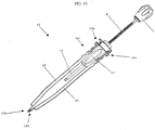
FIG. 1 is a perspective view of one embodiment of an installation tool in use to insert a prosthesis between adjacent vertebrae, distracting adjacent vertebrae; -
FIG. 2 is a perspective view of the installation tool shown inFIG. 1 with an implant in a retracted position; -
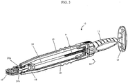
FIG. 3 is a perspective view of the installation tool shown inFIG. 1 with an implant in an advanced position; -
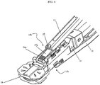
FIG. 4 is a perspective view of the distal end of the installation tool shown inFIG. 3 ; -
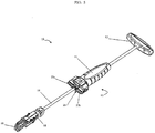
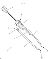
FIG. 5 is a perspective view of a portion of the installation tool shown inFIG. 1 with opposed levers removed; -
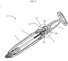
FIG. 6 is a perspective view of one embodiment of a partially assembled installation tool ofFIG. 1 having a split nut female threaded member; -
FIG. 7A is a detailed perspective view of a portion of the installation tool shown inFIG. 3 ; -
FIG. 7B is a detailed perspective view showing a split nut of the installation tool ofFIG. 6 ; -
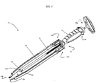
FIG. 8 is a perspective view of another embodiment of an installation tool without an implant holder; -
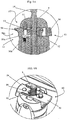
FIG. 9A is a cross-sectional view of a portion of the installation tool ofFIG. 8 ;FIG. 9B is a detailed perspective view of a portion of a half nut female threaded member of the installation tool ofFIG. 8 ; -
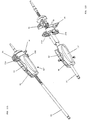
FIG. 10 is a perspective view of another embodiment of an installation tool;FIG. 11A is a perspective view of selected components of the installation tool ofFIG. 10 ; -
FIG. 11B is an assembly view of the portion of the installation tool shown inFIG. 11A ; and -
FIG. 12 is a perspective view of a partially assembled installation tool of the type shown inFIG. 10 . - Certain exemplary embodiments will now be described to provide an overall understanding of the principles, structure, function, manufacture, and use of the devices and methods disclosed herein. One or more examples of these embodiments are illustrated in the accompanying drawings. Those skilled in the art will understand that the devices and methods specifically described herein and illustrated in the accompanying drawings are non-limiting exemplary embodiments and that the scope of the present invention is defined solely by the claims. The features illustrated or described in connection with one exemplary embodiment may be combined with features of other embodiments. Such modifications and variations are intended to be included within the scope of the present invention.
- The present invention provides a medical
device installation tool 10 for implanting a prosthetic device, such as aspinal implant 19, between adjacent vertebral bodies 1a, 1b. In general, and referring toFIG. 1 , theinstallation tool 10 includes abody 12 from which a pair ofopposed levers installation tool 10 also includes adrive rod 14 that is at least partially disposed within thebody 12 and hasthreads 9 formed on at least a portion of an external surface thereof. In one aspect, animplant holder 18 can be coupled to adistal end 14b of thedrive rod 14 and ahandle 13 can be attached to aproximal end 14a of the drive rod. Theimplant holder 18 is, in turn, adapted to be disposed between thelevers implant holder 18 between thelevers levers implant holder 18 and/or theimplant 19 acting on thelevers distal end 14b of thedrive rod 14 can be attached directly to animplant 19, which is adapted to be positioned between thelevers implant 19 between thelevers levers implant 19 and/orimplant holder 18 can be advanced either by rotating thedrive rod 14 or by disengaging thebody 12 from thethreads 9 on thedrive rod 14 to permit longitudinal translation of therod 14 without rotation. - In one embodiment, shown in
FIGS. 1-8 , thebody 12 includes ahandle component 11 at a proximal end thereof and ahousing portion 17, that includes a female threadedmember 28, disposed distally of thehandle 11. One ormore coupling flanges surface 25 of thehousing portion 17. A pair of levers can be removably attached to thecoupling flanges handle 11 can be coupled to thehousing portion 17, or these two components can be separate, but adapted to be positioned adjacent to each other. One skilled in the art will appreciate that the positional relationship of the handle component with respect to the body can be reversed. For example, as illustrated inFIGS. 10-12 , described below in more detail, thehandle component 11 can be disposed at a distal end of thebody 12. - The opposed first and
second levers proximal end distal end FIGS. 7A and8 , the proximal ends 15a, 16a of eachlever mating groove 30 within which acoupling flange engagement members 21a, 21b, can secure thecoupling flanges grooves 30. Theengagement member 21a, 21b is configured such that thelevers body 12 of theinstallation tool 10 to allow attachment of various types of levers to the body, such as levers having varying sizes and geometries. This feature also enables theinstallation tool 10 to be used without the opposed levers 15, 16, for example as shown inFIG. 5 , in the event that the levers are not needed to distract the vertebral bodies. The coupling of thelevers body 12 is such that the levers are able to pivot upon the body such that the distal ends 15b, 16b of the levers are able to separate to distract adjacent vertebrae and to allow passage ofimplant holder 18 and/orimplant 19 therebetween. Such pivotal movement can be accommodated, for example, by utilizing levers having slightly rounded proximal ends 15a, 16a. In addition,coupling flanges tool 10. One skilled in the art will appreciate that the coupling of thelevers body 12 can also be done in such a way as to allow some play (e.g., linear movement) to facilitate convenient use and to accommodate anatomical features or irregularities. - Referring to
FIGS. 2-4 , the distal ends of 15b, 16b of thelevers blade tips blade tips surfaces 27a, 27b that can be beveled or radiused. In one embodiment, outwardly facingsurfaces 27a, 27b can be substantially curved or angled in a superior or inferior direction to facilitate placement of theblade tips surfaces 27a, 27b to enhance boney purchase. For example, surfaces 27a, 27b may include teeth, serrations, or other roughened features. - As
FIG. 4 illustrates, the distal ends 15b, 16b of thelevers surfaces 29 disposed adjacent to theblade tips blade tips - The inwardly facing sides of the
levers levers implant 19 as it moves distally along thelevers levers implant holder 18 and/or an implant. For example, as shown inFIG. 8 , the inwardly facing side of each lever can also include aslot 86 within which a portion of theimplant holder 18 or theimplant 19 can be slidably seated. - As noted above, the
drive rod 14 extends through abore 22 formed in the components of thebody 12. The drive rod can be in the form of an elongate member, adistal portion 14b of which is disposed between thelevers distal end 14b of thedrive rod 14 can include a coupling mechanism 85 (FIG. 8 ), such as a threaded or grooved tip, that can be coupled to animplant holder 18 orimplant 19. Thecoupling mechanism 85 can attach to a corresponding coupling mechanism disposed on theimplant holder 18 and/orimplant 19. For example, theimplant holder 18 orimplant 19 can include a threaded or grooved bore matable with the threaded or grooved end of thedrive rod 14. With such a coupling, forward and rearward motion of therod 14 will effect corresponding motion of thedistal end 14b of therod 14 along the longitudinal axis (x) of thetool 10 and anyimplant holder 18 and/orimplant 19 attached thereto. - As noted above, the
installation tool 10 is designed such that linear translation of animplant holder 18 and/orimplant 19 along thelevers levers - In one embodiment, the
installation tool 10 can include animplant holder 18 which is coupled to thedistal end 14b of therod 14 and disposed between thelevers rod 14 can cause theimplant holder 18 to move between thelevers levers distal end levers blade tips FIG. 2 , in a retracted position, the implant holder 18 (and any attached implant 19) is positioned proximal ofdistal ends levers blade tips implant holder 18 moves distally, the levers pivot and separate such that theblade tips FIGS. 3 and4 , by a distance to allow theimplant holder 18 and/orimplant 19 to pass therebetween. - In one embodiment, the size (e.g., height) of the
implant 19 can determine the amount of separation required between theblade tips larger implant 19 can require a greater amount of separation between theblade tips implant holder 18 and/orimplant 19 can be configured to have various heights, depending upon the amount of separation required between theblade tips implant holder 18 should be selected to cause only the minimum amount of distraction necessary to implant a prosthesis. To this end, thetool 10 can be provided with animplant holder 18 having a selectively adjustable height and/or multiple,interchangeable implant holders 18 having different sizes and shapes. - The
implant holder 18 can also be configured to allow connection of thedistal end 14b of thedrive rod 14 to the implant. In one embodiment, theimplant holder 18 can include a bore extending therethrough. Thedrive rod 14 can extend through the bore such that therod 14 is coupled to theimplant holder 18 and such that at least a portion of the coupling mechanism of therod 14 extends into theimplant holder 18. In this embodiment, the coupling mechanism can mate directly to theimplant 19, or it can mate to a connector element which, in turn, can mate to theimplant 19. - While the
implant holder 18 can be configured to allow connection of thedistal end 14b of thedrive rod 14 to the prosthetic device, theimplant holder 18 can have other configurations as well. In one embodiment, thedistal end 14b of the drive rod can attach to theimplant holder 18 and theimplant holder 18 can include a connection mechanism disposed along the face of theimplant holder 18 that enables theimplant holder 18 to couple directly to the prosthesis device. By way of non-limiting example, the connection mechanism of theimplant holder 18 can include a threaded connection, a dovetail connection, a snap-on connection, or a taper lock connection. - In another embodiment, there is no need for an
implant holder 18. Instead, thecoupling mechanism 85 disposed at thedistal end 14b of thedrive rod 14 can couple directly to animplant 19, and theimplant 19 causes separation of thelevers - As noted above, the
drive rod 14 is at least partially threaded and is adapted to extend through thebore 22 disposed within thebody 12 of theinstallation tool 10. That is, thebore 22 can extend through thehousing 17 and handlecomponent 11. Thehousing 17 includes a mechanism, such as a female threadedmember 28, that enables thethreads 9 of thedrive rod 14 to be selectively engaged or disengaged. When the threads are engaged, the drive rod can move in the axial direction only as a result of rotation of the drive rod. When the threads are disengaged, forward or rearward movement (i.e., linear translation) ofrod 14 can be effected without rotation. - Referring to
FIGS. 6-7B , at least part ofbore 22 is defined by female threadedmember 28. In the embodiment illustrated inFIGS. 1-7B , best shown inFIGS. 6-7B , the female threadedmember 28 is asplit nut 60 having twoseparate sections split nut 60 includes a substantiallyhemispherical groove bore 22 in thebody 12. Thehemispherical groove threads Threads threads 9 on thedrive rod 14. In one embodiment, theseparate sections hemispherical grooves threads grooves threads 9 on thedrive rod 14. This configuration enables longitudinal translation of therod 14 upon rotation of therod 14. In this embodiment, theinstallation tool 10 can include arelease mechanism 26 associated with thebody 12 and adapted to separate theseparate sections threads grooves threads 9 on thedrive rod 14. By disengaging thethreads grooves threads 9 on thedrive rod 14, longitudinal translation of thedrive rod 14 without rotation of therod 14 is permitted. Therelease mechanism 26 can be disposed on thebody 12 and can include a button, switch or other mechanism to trigger the separation of thethreads split nut 60 from thethreads 9 on thedrive rod 14. - In another embodiment (not shown), the
separate sections threads grooves threads 9 on thedrive rod 14 allowing translation of thedrive rod 14 without rotation of therod 14. In this embodiment, anengagement mechanism 26 is adapted to urge thethreads grooves threads 9 on thedrive rod 14 enabling translation of therod 14 only upon rotation of therod 14. Similar to the release mechanism, the engagement mechanism can be disposed on thebody 12 and can include a button, switch or other mechanism to trigger the engagement of thethreads split nut 60 with thethreads 9 on thedrive rod 14. -
FIGS. 8-12 illustrate another embodiment in which the female threadedmember 28 is ahalf nut 90. With reference toFIGS. 8-9B ,half nut 90 has a substantiallyhemispherical groove 91 extending axially therethrough. As with the split nut embodiment, thehemispherical groove 91 of the half nut is aligned with thebore 22 in thebody 12, and at least a portion of thehemispherical groove 91 hasthreads 92 formed thereon. The half nut embodiment can also include a non-threaded portion of thehemispherical groove 91, which can be opposed to the threaded portion, that can be bored to the major diameter of the threaded portion of thedrive rod 14. The half nut embodiment includes anengagement member 94 associated with thebody 12 and adapted to maintain the threadedportion 92 of thehemispherical groove 91 in mating contact with thethreads 9 on thedrive rod 14. In one half nut embodiment, theengagement member 94 is biased to a position in which it is effective to urge thethreads 92 of thehemispherical groove 91 into mating contact with thethreads 9 on thedrive rod 14. As with the split nut embodiment, this configuration enables longitudinal translation of therod 14 only upon rotation of therod 14. In this embodiment, theinstallation tool 10 can include arelease mechanism 96 associated with thebody 12 and adapted to disengage the threadedportion 92 of thehemispherical groove 91 from thethreads 9 on thedrive rod 14. When thethreads 92 of thehemispherical groove 91 are not in mating contact with thethreads 9 on thedrive rod 14, as shown inFIG. 9B , longitudinal translation of thedrive rod 14 without rotation of therod 14 is permitted. - One skilled in the art will appreciate that the
engagement member 94 can alternatively be biased to a position in which the threadedportion 92 of thehemispherical groove 91 is disengaged from thethreads 9 on thedrive rod 14. In this embodiment (shown inFIG. 9A ), thethreads 92 of thehemispherical groove 91 can be urged into mating contact with thethreads 9 on thedrive rod 14 by applying force to theengagement member 94. Pressing theengagement member 94 inward can cause therelease mechanism 96 to move outwardly and lock into an engaged position. For example, in one embodiment, alocking mechanism 97 associated with thehalf nut 90 can include aspring 93 that is held in position by astationary pin 95. Thespring 93 can be compressed such that it applies a constant downward force on therelease mechanism 96. In this embodiment, therelease mechanism 96 includes a lockingportion 96a and aclearance portion 96b. As force is applied to theengagement member 94, therelease mechanism 96 slides outward. Once the lockingportion 96a has cleared the sidewall of the installation tool, therelease mechanism 96 is forced downward by thespring 93 and locked in place. The lockingportion 96a can be adapted to fit against the sidewall of the tool, thereby holding therelease mechanism 96 in place and maintaining the thread engagement. To disengage the threads, force can be applied to a scallopedportion 96c of therelease mechanism 96 in an upward and inward direction, thereby unlocking therelease mechanism 96 and urging thethreads 92 of thehemispherical groove 91 away from thethreads 9 on thedrive rod 14. - It is possible to use various body designs without departing from the scope of invention.
FIGS. 1-7B illustrate an embodiment in which thebody 12 is relatively small with only minimal surface area contact betweenbody 12 and levers 15, 16. Alternatively,FIGS. 10-12 illustrate an embodiment that affords more surface area contact between the body 12', potentially providing additional stability of the levers. One skilled in the art will appreciate that the half-nut or split nut designs can be used with either body configuration. - With further reference to
FIGS. 10-12 , the somewhat larger body 12' includesgrooves 82 formed on opposed sides of handle component 11', which are adapted to seat thelevers body 12 can also includecoupling flanges groove 82 and a stabilizingflange 84 disposed at a distal portion of eachgroove 82. AsFIG. 12 illustrates, thelevers grooves 82 such that a portion of each lever seats both thecoupling flange flange 84. -
FIGS. 1-4 illustrate the use of aninstallation tool 10 for the implantation of aprosthetic device 19, such as an intervertebral implant. As illustrated inFIG. 2 , thetool 10 can be assembled in one embodiment with thedrive rod 14 coupled to animplant holder 18 and animplant 19 disposed in theholder 18. For example, the tool can be configured in a rotation mode in which rotation ofhandle 13 will cause the shaft to rotate so that it can be threaded into theimplant holder 18. In an initial state, theimplant holder 18 can be positioned in proximity to aproximal end levers blade tips blade tips tool 10 can be manipulated such that theblade tips levers FIG. 5 , thetool 10 can also be used for installation of a prosthetic device without the use ofopposed levers tool 10 is used only for placement of an implant and not for distraction of the vertebral bodies. - As illustrated in
FIG. 3 , thedrive rod 14 and theimplant holder 18 and/orimplant 19 can then be advanced distally along the longitudinal axis (x) of theinstallation tool 10. For example, with thetool 10 in a rotation mode, rotation of thehandle 13 disposed at the proximal end of thedrive rod 14 will cause therod 14 to translate along the longitudinal axis and advance theimplant holder 18 and/orimplant 19 toward the vertebral bodies 1a, 1b. In addition to the rotation mode, the selectively engageable female threadedmember 28 allows the surgeon to easily switch from rotation mode to translation mode. Thus, the surgeon can quickly advance theimplant 19 to a distal portion of theinstallation tool 10 in translation mode and switch to rotation mode, once it is necessary to distractblade tips implant 19. As a result, the distal movement of theimplant holder 18 and/orimplant 19 between thelevers blade tips implant holder 18 continues until, as shown inFIGS. 3-4 , theimplant 19 extends beyond theblade tips implant 19 is properly installed between the adjacent vertebral bodies 1a, 1b. When the implant reaches its final position, continued translation of the shaft draws the opposed levers from the disc space leaving only the implant in the disc space.FIGS. 1-3 illustrate that at all times separation of the vertebral bodies is only effected to the extent necessary to insert the prosthetic device. Excessive distraction or separation of the vertebral bodies does not occur because the separation of vertebral bodies is caused by the height of theimplant holder 18 and/orimplant 19. - If the
drive rod 14 is connected directly to animplant 19, continued rotation of therod 14 after placement of theimplant 19 will decouple therod 14 from theimplant 19. Once thedrive rod 14 has been disconnected from theimplant 19, theinsertion tool 10 can be removed from between the adjacent vertebral bodies 1a, 1b. For example, this feature can be useful to install a trial implant without impaction. The drive rod can be coupled directly to the trial. Continued rotation of the rod after placement will withdraw the opposed levers from the disk space leaving only the trial and allowing the trial to be easily decoupled from the insertion instrument. - The installation tool of the present invention can also be provided as a kit having modular components which allow the surgeon to select from among a variety of components to assemble an installation tool that is optimized for its intended use. The kit may include several different levers, drive rods, implant holders, and other elements, each adapted to be used with a particular type or size of implant. For example, the kit can include different types of implant holders, each adapted to mate with a particular prosthesis. A person skilled in the art will appreciate that the installation tool can include a variety of components having a combination of different features. Moreover, the components can be adapted for use with particular types of prosthesis, or for use with other components.
- One skilled in the art will appreciate further features and advantages of the invention based on the above-described embodiments. Accordingly, the invention is not to be limited by what has been particularly shown and described, except as indicated by the appended claims. All publications and references cited herein are expressly incorporated herein by reference in their entirety.
- Where the female threaded member of the medical device installation tool of the present invention comprises a split nut having two separate sections, each section including a substantially hemispherical groove extending axially therethrough, each hemispherical groove having threads formed on at least a portion thereof, and where the separate sections are biased to a joined position such that the hemispherical grooves are aligned to form a substantially cylindrical bore and the threads in the grooves are adapted to mate with the threads on the drive rod, the medical device installation tool may further comprise a release mechanism adapted to separate the separate sections such that the threads in the grooves are unable to mate with the threads on the drive rod. Where the female threaded member of the medical device installation tool comprises a split nut having two separate sections, each section including a substantially hemispherical groove extending axially therethrough, each hemispherical groove having threads formed on at least a portion thereof, the separate sections may be biased to a separated position in which the threads in the grooves are unable to mate with the threads on the drive rod. The medical device installation tool may further comprise an engagement mechanism adapted to urge the threads in the grooves into mating contact with the threads on the drive rod.
- The female threaded member of the medical device installation tool may comprise a half nut having a substantially hemispherical groove extending axially therethrough, the groove having threads formed on at least a portion thereof. The medical device installation tool may further comprise an engagement member associated with the half nut, the engagement member adapted to maintain the threads of the hemispherical groove in mating contact with the threads of the drive rod. The engagement member may be biased to a position in which it is effective to urge the threads in the groove into mating contact with the threads of the drive rod and the tool may further comprise a release mechanism adapted to separate the threads in the groove from the threads on the drive rod. The engagement member may be biased to a position in which it is effective to separate the threads in the groove from the threads on the drive rod and the tool may further comprise a release mechanism adapted to urge the threads in the groove into mating contact with the threads of the drive rod. The medical device installation tool may further comprise a locking mechanism associated with the half nut, the locking mechanism adapted to maintain the thread engagement.
- The present invention may also provide a medical device installation tool, comprising:
- a body having a bore extending therethrough;
- a drive rod adapted to extend through the bore, the drive rod having a proximal end and a distal end with threads formed on at least a portion of a surface thereof; and
- a pair of opposed levers, each having a proximal end and a distal end, the proximal end of each lever being pivotally coupled to a portion of the body; and
- the body having at least a partial female thread formed in at least a portion of the bore, the female thread being selectively engageable in (1) a drive rod rotation configuration in which the female thread is engaged with the threads on the rod to permit longitudinal translation of the rod upon rotation of the rod and (2) a translation configuration in which the female thread is disengaged from the threads on the rod to permit longitudinal translation of the rod upon translation of the rod without rotation of the rod.
- The present invention may also provide a method for implanting a prosthetic device, comprising:
- disposing portions of opposed, pivotable levers of an installation tool between vertebral bodies;
- advancing the prosthesis toward a distal end of the installation tool by longitudinal movement of the drive rod without rotation of the drive rod;
- establishing a threaded connection between a portion of the drive rod and a portion of the installation tool to enable longitudinal translation of the prosthesis upon rotation of the drive rod; and
- rotating the drive rod to longitudinally advance the prosthesis to an implantation site.
Claims (15)
- A medical device installation tool (10), comprising:a body (12) having a bore extending therethrough;a drive rod (14) adapted to extend through the bore, the drive rod having a proximal end and a distal end with threads formed on at least a portion of a surface thereof;a pair of opposed levers (15,16) each having a proximal end and a distal end, the proximal end of each lever being pivotally coupled to a portion of the body; anda female threaded member associated with the body and having at least a partial female thread formed in at least a portion of the bore, the female threaded member being selectively engageable in 1) a drive rod rotation configuration in which the partial female thread is engaged with the threads on the rod such that the rod is longitudinally translatable relative to the body upon rotation of the rod relative to the body and 2) a translation configuration in which the female threaded member is disengaged from the threads on the rod such that the rod is longitudinally translatable within the bore without rotation of the rod relative to the body;wherein the female threaded member comprises a split nut (60) having two separate sections, each section including a substantially hemicylindrical groove extending axially therethrough, each hemicylindrical groove having threads formed on at least a portion thereof.
- The medical device installation tool of claim 1, wherein the distal end of the drive rod is adapted to engage an implant.
- The medical device installation tool of claim 1, further comprising an implant holder disposed at the distal end of the drive rod.
- The medical device installation tool of claim 3, wherein the implant holder has a selectively adjustable height.
- The medical device installation tool of claim 1, further comprising a handle disposed at the proximal end of the drive rod.
- The medical device installation tool of claim 1, further comprising a supply of lever pairs of varying sizes and configurations.
- The medical device installation tool of claim 1, wherein the body includes a handle component at a proximal end thereof.
- The medical device installation tool of claim 7, wherein the levers are removably coupled to a distal most portion of the body.
- The medical device installation tool of claim 8, wherein each lever is coupled to a coupling flange formed on a distal facing surface of the body.
- The medical device installation tool of claim 1, wherein a handle component is disposed at a distal end of the body.
- The medical device installation tool of claim 10, wherein opposed sides of the handle component have a groove formed thereon with a coupling flange disposed at a proximal portion of each groove and a stabilizing flange disposed at a distal portion of each groove.
- The medical device installation tool of claim 11, wherein each lever has a slot formed in at least a portion of a medial side thereof, the slot adapted to seat the stabilizing flange.
- The medical device installation tool of claim 11, wherein the levers are removably attached within the groove of the handle component such that a portion of each lever seats both the coupling flange and the stabilizing flange.
- The medical device installation tool of claim 1, wherein the separate sections are biased to a joined position such that the hemicylindrical grooves are aligned to form a substantially cylindrical bore and the threads in the grooves are adapted to mate with the threads on the drive rod.
- The medical device installation tool of claim 11, wherein the female threaded member is biased to the drive rod rotation configuration such that releasing the female threaded member from the translation configuration automatically moves the female threaded member to the drive rod rotation configuration.
Applications Claiming Priority (2)
| Application Number | Priority Date | Filing Date | Title |
|---|---|---|---|
| US11/347,991 US8377072B2 (en) | 2006-02-06 | 2006-02-06 | Medical device installation tool |
| PCT/US2007/001660 WO2007092147A2 (en) | 2006-02-06 | 2007-01-22 | Medical device installation tool |
Publications (3)
| Publication Number | Publication Date |
|---|---|
| EP1981391A2 EP1981391A2 (en) | 2008-10-22 |
| EP1981391A4 EP1981391A4 (en) | 2015-08-05 |
| EP1981391B1 true EP1981391B1 (en) | 2017-11-15 |
Family
ID=38334932
Family Applications (1)
| Application Number | Title | Priority Date | Filing Date |
|---|---|---|---|
| EP07716891.2A Not-in-force EP1981391B1 (en) | 2006-02-06 | 2007-01-22 | Medical device installation tool |
Country Status (4)
| Country | Link |
|---|---|
| US (1) | US8377072B2 (en) |
| EP (1) | EP1981391B1 (en) |
| AU (1) | AU2007212750B2 (en) |
| WO (1) | WO2007092147A2 (en) |
Families Citing this family (60)
| Publication number | Priority date | Publication date | Assignee | Title |
|---|---|---|---|---|
| US7887539B2 (en) | 2003-01-24 | 2011-02-15 | Depuy Spine, Inc. | Spinal rod approximators |
| US7988698B2 (en) | 2003-01-28 | 2011-08-02 | Depuy Spine, Inc. | Spinal rod approximator |
| US7842044B2 (en) | 2003-12-17 | 2010-11-30 | Depuy Spine, Inc. | Instruments and methods for bone anchor engagement and spinal rod reduction |
| US7722622B2 (en) * | 2005-02-25 | 2010-05-25 | Synthes Usa, Llc | Implant insertion apparatus and method of use |
| US7951172B2 (en) | 2005-03-04 | 2011-05-31 | Depuy Spine Sarl | Constrained motion bone screw assembly |
| US7951175B2 (en) | 2005-03-04 | 2011-05-31 | Depuy Spine, Inc. | Instruments and methods for manipulating a vertebra |
| US20060293692A1 (en) | 2005-06-02 | 2006-12-28 | Whipple Dale E | Instruments and methods for manipulating a spinal fixation element |
| US8172847B2 (en) * | 2007-03-29 | 2012-05-08 | Depuy Spine, Inc. | In-line rod reduction device and methods |
| US8486081B2 (en) * | 2007-07-23 | 2013-07-16 | DePuy Synthes Products, LLC | Implant insertion device and method |
| US20090030420A1 (en) | 2007-07-26 | 2009-01-29 | Depuy Spine, Inc. | Spinal rod reduction instruments and methods for use |
| EP2194930B1 (en) * | 2007-08-13 | 2014-05-07 | Stryker Spine | Insertion instrument for intervertebral implants |
| US8790348B2 (en) | 2007-09-28 | 2014-07-29 | Depuy Spine, Inc. | Dual pivot instrument for reduction of a fixation element and method of use |
| US8142441B2 (en) * | 2008-10-16 | 2012-03-27 | Aesculap Implant Systems, Llc | Surgical instrument and method of use for inserting an implant between two bones |
| US8591587B2 (en) | 2007-10-30 | 2013-11-26 | Aesculap Implant Systems, Llc | Vertebral body replacement device and method for use to maintain a space between two vertebral bodies within a spine |
| US8709015B2 (en) * | 2008-03-10 | 2014-04-29 | DePuy Synthes Products, LLC | Bilateral vertebral body derotation system |
| US8608746B2 (en) | 2008-03-10 | 2013-12-17 | DePuy Synthes Products, LLC | Derotation instrument with reduction functionality |
| US9060757B2 (en) | 2008-05-05 | 2015-06-23 | Ranier Limited | Distractor |
| USD626649S1 (en) * | 2008-06-06 | 2010-11-02 | Atlas Spine, Inc. | Distractor |
| US10973556B2 (en) | 2008-06-17 | 2021-04-13 | DePuy Synthes Products, Inc. | Adjustable implant assembly |
| KR100897928B1 (en) | 2008-12-23 | 2009-05-18 | 박윤관 | Elevation device for spinal condyle extension |
| US9480511B2 (en) | 2009-12-17 | 2016-11-01 | Engage Medical Holdings, Llc | Blade fixation for ankle fusion and arthroplasty |
| US8545505B2 (en) * | 2010-01-15 | 2013-10-01 | Pioneer Surgical Technology, Inc. | Low friction rod persuader |
| US20110208090A1 (en) * | 2010-02-22 | 2011-08-25 | Parihar Shailendra K | Spring Loaded Biopsy Device |
| US8540724B2 (en) * | 2010-04-30 | 2013-09-24 | Lanx, Inc. | Anterior distractor-inserter with linear countersink adjustment |
| EP2629714B1 (en) | 2010-10-18 | 2015-12-30 | Apollo Endosurgery, Inc. | Intragastric implants with duodenal anchors |
| EP2629716B1 (en) | 2010-10-19 | 2016-07-13 | Apollo Endosurgery, Inc. | Anchored non-piercing duodenal sleeve |
| US9498365B2 (en) | 2010-10-19 | 2016-11-22 | Apollo Endosurgery, Inc. | Intragastric implants with multiple fluid chambers |
| US8864840B2 (en) | 2010-10-19 | 2014-10-21 | Apollo Endosurgery, Inc. | Intragastric implants with collapsible frames |
| US8920447B2 (en) | 2010-10-19 | 2014-12-30 | Apollo Endosurgery, Inc. | Articulated gastric implant clip |
| EP3178448B1 (en) | 2010-12-16 | 2018-08-01 | Engage Medical Holdings, LLC | Arthroplasty systems |
| US8500749B2 (en) * | 2011-04-19 | 2013-08-06 | Prescient Surgical Designs, Llc | Apparatus and method for inserting intervertebral implants |
| US9254130B2 (en) | 2011-11-01 | 2016-02-09 | Hyun Bae | Blade anchor systems for bone fusion |
| WO2013067179A2 (en) | 2011-11-01 | 2013-05-10 | Synthes Usa, Llc | Dilation system |
| US9615856B2 (en) | 2011-11-01 | 2017-04-11 | Imds Llc | Sacroiliac fusion cage |
| US9358124B2 (en) | 2012-02-29 | 2016-06-07 | Globus Medical, Inc. | Implant inserter |
| US9186263B2 (en) | 2012-02-29 | 2015-11-17 | Globus Medical, Inc. | Implant inserter |
| US10238382B2 (en) | 2012-03-26 | 2019-03-26 | Engage Medical Holdings, Llc | Blade anchor for foot and ankle |
| US9451998B2 (en) * | 2012-08-17 | 2016-09-27 | Warsaw Orthopedic, Inc. | Spinal implant system and method |
| US9381051B2 (en) | 2014-07-31 | 2016-07-05 | Innovasis, Inc. | Reduction jack for spinal rod placement and method of use |
| ES2966771T3 (en) | 2016-02-02 | 2024-04-24 | Aesculap Ag | Instrument for guiding a rod into an implant housing |
| DE102016101822A1 (en) * | 2016-02-02 | 2017-08-03 | Aesculap Ag | Instrument for guiding a rod into an implant receptacle |
| US10543106B2 (en) * | 2016-04-05 | 2020-01-28 | Alphatec Spine, Inc. | Inserter with impact and rotational drive advancement and implant holder with implant auto release |
| US10390955B2 (en) | 2016-09-22 | 2019-08-27 | Engage Medical Holdings, Llc | Bone implants |
| US10456272B2 (en) | 2017-03-03 | 2019-10-29 | Engage Uni Llc | Unicompartmental knee arthroplasty |
| US11540928B2 (en) | 2017-03-03 | 2023-01-03 | Engage Uni Llc | Unicompartmental knee arthroplasty |
| US10966762B2 (en) | 2017-12-15 | 2021-04-06 | Medos International Sarl | Unilateral implant holders and related methods |
| US10905566B2 (en) * | 2018-02-05 | 2021-02-02 | Spineology Inc. | Percutaneous posterior implant slide |
| US11324609B2 (en) | 2018-04-20 | 2022-05-10 | JWD Products, LLC | Spinal implant insertion tool |
| US10932922B2 (en) | 2018-04-20 | 2021-03-02 | JWD Products, LLC | Spinal implant insertion tool |
| CN109172056B (en) * | 2018-09-06 | 2023-11-14 | 北京市春立正达医疗器械股份有限公司 | Press fitting tool for reverse shoulder joint prosthesis |
| EP3852820B1 (en) | 2018-09-17 | 2024-11-20 | Board of Regents, The University of Texas System | Compositions and methods for treating bone injury |
| USD1004774S1 (en) | 2019-03-21 | 2023-11-14 | Medos International Sarl | Kerrison rod reducer |
| US11291482B2 (en) | 2019-03-21 | 2022-04-05 | Medos International Sarl | Rod reducers and related methods |
| US11291481B2 (en) | 2019-03-21 | 2022-04-05 | Medos International Sarl | Rod reducers and related methods |
| US11452617B2 (en) * | 2019-09-09 | 2022-09-27 | Integrity Implants Inc. | Dynamic expanding pathway cannula |
| US11963887B2 (en) * | 2020-07-06 | 2024-04-23 | Medos International Sarl | Expandable cage adjustment tool and method |
| EP4240262B1 (en) | 2020-11-09 | 2024-12-04 | Medos International Sàrl | Biplanar forceps reducers |
| EP4432942A1 (en) | 2021-11-19 | 2024-09-25 | Medos International Sarl | Reducer locking mechanisms |
| US12544234B2 (en) | 2022-04-07 | 2026-02-10 | Linares Spinal Devices, Llc | Expandable worm screw jack for installation between upper and lower succeeding articular processes and having enhanced bone gripping geometry and teeth profiles |
| CN116531151A (en) * | 2023-06-01 | 2023-08-04 | 中国人民解放军南部战区总医院 | An atlantoaxial mass joint expansion reduction device |
Family Cites Families (140)
| Publication number | Priority date | Publication date | Assignee | Title |
|---|---|---|---|---|
| US1934818A (en) * | 1930-07-08 | 1933-11-14 | Gustav F Richter | Surgical instrument |
| US2102602A (en) * | 1935-09-28 | 1937-12-21 | Steel Nut & Joseph Hampton Ltd | Vise |
| US3486505A (en) * | 1967-05-22 | 1969-12-30 | Gordon M Morrison | Orthopedic surgical instrument |
| US4034746A (en) * | 1975-08-01 | 1977-07-12 | Williams Robert W | Retractor |
| SE411703B (en) * | 1977-11-29 | 1980-02-04 | Mo Och Domsjoe Ab | INSTRUMENTS FOR SURGICAL INTERVENTIONS IN A LED |
| US4369788A (en) * | 1980-01-31 | 1983-01-25 | Goald Harold J | Reversed forceps for microdisc surgery |
| US4337576A (en) * | 1980-11-06 | 1982-07-06 | Drost Jim L | Knife with retractable blade |
| US4545374A (en) | 1982-09-03 | 1985-10-08 | Jacobson Robert E | Method and instruments for performing a percutaneous lumbar diskectomy |
| US4877020A (en) | 1984-11-30 | 1989-10-31 | Vich Jose M O | Apparatus for bone graft |
| US4660287A (en) * | 1985-11-01 | 1987-04-28 | Decker John R | Knife with replaceable blade |
| US4730613A (en) * | 1986-06-13 | 1988-03-15 | Cilco, Inc. | Surgical scalpel |
| US4735202A (en) * | 1986-10-06 | 1988-04-05 | Alcon Laboratories, Inc. | Microsurgical knife with locking blade guard |
| DE3707097A1 (en) * | 1986-12-05 | 1988-06-09 | S & G Implants Gmbh | PLIERS FOR SPREADING SPINE BODIES |
| US5019081A (en) * | 1986-12-10 | 1991-05-28 | Watanabe Robert S | Laminectomy surgical process |
| US4772287A (en) | 1987-08-20 | 1988-09-20 | Cedar Surgical, Inc. | Prosthetic disc and method of implanting |
| DE3809793A1 (en) * | 1988-03-23 | 1989-10-05 | Link Waldemar Gmbh Co | SURGICAL INSTRUMENT SET |
| AU7139994A (en) * | 1988-06-13 | 1995-01-03 | Karlin Technology, Inc. | Apparatus and method of inserting spinal implants |
| US5015247A (en) * | 1988-06-13 | 1991-05-14 | Michelson Gary K | Threaded spinal implant |
| US5484437A (en) * | 1988-06-13 | 1996-01-16 | Michelson; Gary K. | Apparatus and method of inserting spinal implants |
| US5052373A (en) | 1988-07-29 | 1991-10-01 | Michelson Gary K | Spinal retractor |
| US5139507A (en) * | 1989-04-06 | 1992-08-18 | Stuart Dolgin | Surgical scalpel with retractable blade guard |
| US5055104A (en) | 1989-11-06 | 1991-10-08 | Surgical Dynamics, Inc. | Surgically implanting threaded fusion cages between adjacent low-back vertebrae by an anterior approach |
| US5059194A (en) | 1990-02-12 | 1991-10-22 | Michelson Gary K | Cervical distractor |
| FR2659226B1 (en) * | 1990-03-07 | 1992-05-29 | Jbs Sa | PROSTHESIS FOR INTERVERTEBRAL DISCS AND ITS IMPLEMENTATION INSTRUMENTS. |
| US5254128A (en) * | 1990-10-11 | 1993-10-19 | Micro Engineering, Inc. | Surgical knife with attached, movable blade protector |
| US5020519A (en) * | 1990-12-07 | 1991-06-04 | Zimmer, Inc. | Sagittal approximator |
| GB9110778D0 (en) * | 1991-05-18 | 1991-07-10 | Middleton Jeffrey K | Apparatus for use in surgery |
| US5496340A (en) * | 1992-01-24 | 1996-03-05 | Leonard Bloom | Combination guarded surgical scalpel and blade stripper |
| US5411512A (en) | 1992-01-24 | 1995-05-02 | Leonard Bloom | Guarded surgical scalpel |
| US5213112A (en) * | 1992-01-29 | 1993-05-25 | Pfizer Hospital Products Group, Inc. | Tension meter for orthopedic surgery |
| US5306248A (en) * | 1992-04-07 | 1994-04-26 | C. R. Bard, Inc. | Selectively controllable inflation-deflation device adapted for use in angioplasty procedures |
| US5306309A (en) | 1992-05-04 | 1994-04-26 | Calcitek, Inc. | Spinal disk implant and implantation kit |
| US5531754A (en) * | 1992-07-24 | 1996-07-02 | Shackelford, Sr.; Howard L. | Retractable surgical blade device and associated method |
| US5292329A (en) * | 1992-12-04 | 1994-03-08 | Werner Richard S | Retractable surgical knife |
| US5569282A (en) | 1992-12-04 | 1996-10-29 | Werner; Richard S. | Retractable surgical knife |
| US5423843A (en) * | 1992-12-04 | 1995-06-13 | Werner; Richard S. | Retractable surgical knife |
| US5779724A (en) * | 1992-12-04 | 1998-07-14 | Werner; Richard S. | Retractable surgical knife |
| ES2231110T3 (en) | 1993-06-10 | 2005-05-16 | Karlin Technology, Inc. | VERTEBRAL SEPARATOR. |
| US5304119A (en) * | 1993-06-24 | 1994-04-19 | Monsanto Company | Instrument for injecting implants through animal hide |
| DE4328690B4 (en) | 1993-08-26 | 2006-08-17 | SDGI Holdings, Inc., Wilmington | Intervertebral implant for vertebral body blocking and implantation instrument for positioning the intervertebral implant |
| BE1007549A3 (en) * | 1993-09-21 | 1995-08-01 | Beckers Louis Francois Charles | Implant. |
| US5443514A (en) * | 1993-10-01 | 1995-08-22 | Acromed Corporation | Method for using spinal implants |
| US5599351A (en) * | 1993-12-08 | 1997-02-04 | Habley Medical Technology Corporation | Scalpels having permanent blade retraction |
| US5431658A (en) * | 1994-02-14 | 1995-07-11 | Moskovich; Ronald | Facilitator for vertebrae grafts and prostheses |
| AU651790B3 (en) * | 1994-03-17 | 1994-07-28 | Noble House Group Pty Ltd | Scalpel |
| US5431672A (en) * | 1994-05-09 | 1995-07-11 | Becton, Dickinson And Company | Surgical scalpel with retractable blade |
| US5403337A (en) * | 1994-07-05 | 1995-04-04 | Platts; David | Retractable-bladed surgical scalpel |
| US5885299A (en) * | 1994-09-15 | 1999-03-23 | Surgical Dynamics, Inc. | Apparatus and method for implant insertion |
| US5481804A (en) * | 1994-10-12 | 1996-01-09 | Platts; David | Retractable-bladed knife |
| US5562736A (en) | 1994-10-17 | 1996-10-08 | Raymedica, Inc. | Method for surgical implantation of a prosthetic spinal disc nucleus |
| US5620454A (en) * | 1994-10-25 | 1997-04-15 | Becton, Dickinson And Company | Guarded surgical scalpel |
| US5827309A (en) | 1994-10-25 | 1998-10-27 | Becton, Dickinson And Company | Guarded surgical scalpel with scalpel blade remover |
| US5766252A (en) * | 1995-01-24 | 1998-06-16 | Osteonics Corp. | Interbody spinal prosthetic implant and method |
| US5665099A (en) | 1995-05-12 | 1997-09-09 | Pilo; Giuseppe | Surgical scalpel with automatically retractable blade |
| US5683391A (en) | 1995-06-07 | 1997-11-04 | Danek Medical, Inc. | Anterior spinal instrumentation and method for implantation and revision |
| US5782830A (en) * | 1995-10-16 | 1998-07-21 | Sdgi Holdings, Inc. | Implant insertion device |
| US5683407A (en) | 1995-10-19 | 1997-11-04 | Becton, Dickinson And Company | Cleanable guarded surgical scalpel with scalpel blade remover |
| GB2306653B (en) | 1995-10-23 | 1999-12-15 | Finsbury | Surgical tool |
| IT1276991B1 (en) * | 1995-10-24 | 1997-11-03 | Giuseppe Pilo | DISPOSABLE SURGICAL SCALPEL FOR SAFETY |
| US5935151A (en) * | 1995-12-15 | 1999-08-10 | Broughton; Bruce G. | Vertebral distraction pump |
| US5645597A (en) * | 1995-12-29 | 1997-07-08 | Krapiva; Pavel I. | Disc replacement method and apparatus |
| US5722977A (en) * | 1996-01-24 | 1998-03-03 | Danek Medical, Inc. | Method and means for anterior lumbar exact cut with quadrilateral osteotome and precision guide/spacer |
| CA2199462C (en) * | 1996-03-14 | 2006-01-03 | Charles J. Winslow | Method and instrumentation for implant insertion |
| JP3819962B2 (en) * | 1996-04-01 | 2006-09-13 | ペンタックス株式会社 | Interbody fusion implant guide device |
| US6063088A (en) * | 1997-03-24 | 2000-05-16 | United States Surgical Corporation | Method and instrumentation for implant insertion |
| US5720751A (en) * | 1996-11-27 | 1998-02-24 | Jackson; Roger P. | Tools for use in seating spinal rods in open ended implants |
| US5951564A (en) | 1996-12-18 | 1999-09-14 | Bristol-Myers Squibb Company | Orthopaedic positioning apparatus |
| US5732992A (en) * | 1996-12-26 | 1998-03-31 | Exactech, Incorporated | Medical appliance tool providing one hand actuation |
| US6902566B2 (en) * | 1997-01-02 | 2005-06-07 | St. Francis Medical Technologies, Inc. | Spinal implants, insertion instruments, and methods of use |
| US6042582A (en) * | 1997-05-20 | 2000-03-28 | Ray; Charles D. | Instrumentation and method for facilitating insertion of spinal implant |
| CA2238117C (en) | 1997-05-30 | 2006-01-10 | United States Surgical Corporation | Method and instrumentation for implant insertion |
| US5868771A (en) * | 1997-07-25 | 1999-02-09 | Pabban Development, Inc. | Scalpel blade cover |
| US6086595A (en) | 1997-08-29 | 2000-07-11 | Sulzer Spine-Tech Inc. | Apparatus and method for spinal stabilization |
| US6004326A (en) | 1997-09-10 | 1999-12-21 | United States Surgical | Method and instrumentation for implant insertion |
| US5944658A (en) * | 1997-09-23 | 1999-08-31 | Koros; Tibor B. | Lumbar spinal fusion retractor and distractor system |
| US6159215A (en) | 1997-12-19 | 2000-12-12 | Depuy Acromed, Inc. | Insertion instruments and method for delivering a vertebral body spacer |
| US6020237A (en) | 1998-02-04 | 2000-02-01 | Alliance Semiconductor Corporation | Method of reducing dielectric damage due to charging in the fabrication of stacked gate structures |
| US5957927A (en) | 1998-02-24 | 1999-09-28 | Synthes (Usa) | Bone fixation device introducer |
| US5908432A (en) * | 1998-03-27 | 1999-06-01 | Pan; Huai C. | Scalpel with retractable blade |
| US6197033B1 (en) * | 1998-04-09 | 2001-03-06 | Sdgi Holdings, Inc. | Guide sleeve for offset vertebrae |
| US6083228A (en) * | 1998-06-09 | 2000-07-04 | Michelson; Gary K. | Device and method for preparing a space between adjacent vertebrae to receive an insert |
| US6015419A (en) * | 1998-08-31 | 2000-01-18 | Strome Steel Surgical, Inc. | Retractable surgical scalpel |
| US6117174A (en) | 1998-09-16 | 2000-09-12 | Nolan; Wesley A. | Spinal implant device |
| EP1117335B1 (en) | 1998-10-02 | 2009-03-25 | Synthes GmbH | Spinal disc space distractor |
| US7189234B2 (en) | 1998-10-20 | 2007-03-13 | St. Francis Medical Technologies, Inc. | Interspinous process implant sizer and distractor with a split head and size indicator and method |
| CA2352185C (en) | 1998-11-26 | 2008-04-15 | Synthes (U.S.A.) | Bone screw having a constant diameter thread |
| US6159244A (en) | 1999-07-30 | 2000-12-12 | Suddaby; Loubert | Expandable variable angle intervertebral fusion implant |
| DE19903762C1 (en) | 1999-01-30 | 2000-11-16 | Aesculap Ag & Co Kg | Surgical instrument for inserting intervertebral implants |
| US6648895B2 (en) | 2000-02-04 | 2003-11-18 | Sdgi Holdings, Inc. | Methods and instrumentation for vertebral interbody fusion |
| CA2361069A1 (en) * | 1999-02-04 | 2000-08-10 | Sdgi Holdings, Inc. | Methods and instrumentation for vertebral interbody fusion |
| US6743234B2 (en) * | 1999-02-04 | 2004-06-01 | Sdgi Holdings, Inc. | Methods and instrumentation for vertebral interbody fusion |
| US6220124B1 (en) * | 1999-03-04 | 2001-04-24 | Speed Set, Inc. | Fire hydrant wrench |
| US6113602A (en) | 1999-03-26 | 2000-09-05 | Sulzer Spine-Tech Inc. | Posterior spinal instrument guide and method |
| US6267763B1 (en) * | 1999-03-31 | 2001-07-31 | Surgical Dynamics, Inc. | Method and apparatus for spinal implant insertion |
| US6168601B1 (en) * | 1999-05-14 | 2001-01-02 | Giuseppe Martini | Lock reduction device and method |
| US6159212A (en) | 1999-08-02 | 2000-12-12 | Schoedinger, Iii; George R. | Surgical tool and method to reduce vertebral displacement |
| US6200322B1 (en) * | 1999-08-13 | 2001-03-13 | Sdgi Holdings, Inc. | Minimal exposure posterior spinal interbody instrumentation and technique |
| CA2382453A1 (en) * | 1999-08-26 | 2001-03-01 | Sdgi Holdings, Inc. | Devices and methods for implanting fusion cages |
| JP2003509118A (en) | 1999-09-14 | 2003-03-11 | スパイン ソリューションズ インコーポレイテッド | Intervertebral implant insertion device |
| US6436119B1 (en) * | 1999-09-30 | 2002-08-20 | Raymedica, Inc. | Adjustable surgical dilator |
| US6277122B1 (en) * | 1999-10-15 | 2001-08-21 | Sdgi Holdings, Inc. | Distraction instrument with fins for maintaining insertion location |
| US6520967B1 (en) | 1999-10-20 | 2003-02-18 | Cauthen Research Group, Inc. | Spinal implant insertion instrument for spinal interbody prostheses |
| US6319257B1 (en) | 1999-12-20 | 2001-11-20 | Kinamed, Inc. | Inserter assembly |
| US6569168B2 (en) | 2000-05-05 | 2003-05-27 | Osteotech, Inc. | Intervertebral distractor and implant insertion instrument |
| US6478800B1 (en) * | 2000-05-08 | 2002-11-12 | Depuy Acromed, Inc. | Medical installation tool |
| DE10035182C2 (en) | 2000-07-20 | 2002-07-11 | Aesculap Ag & Co Kg | Insertion tool for an intervertebral implant |
| US7204851B2 (en) * | 2000-08-30 | 2007-04-17 | Sdgi Holdings, Inc. | Method and apparatus for delivering an intervertebral disc implant |
| US6599291B1 (en) * | 2000-10-20 | 2003-07-29 | Sdgi Holdings, Inc. | Methods and instruments for interbody surgical techniques |
| US7115132B2 (en) * | 2001-07-16 | 2006-10-03 | Spinecore, Inc. | Static trials and related instruments and methods for use in implanting an artificial intervertebral disc |
| US7169182B2 (en) | 2001-07-16 | 2007-01-30 | Spinecore, Inc. | Implanting an artificial intervertebral disc |
| US7575576B2 (en) * | 2001-07-16 | 2009-08-18 | Spinecore, Inc. | Wedge ramp distractor and related methods for use in implanting artificial intervertebral discs |
| US6716218B2 (en) | 2001-02-28 | 2004-04-06 | Hol-Med Corporation | Instrument for bone distraction and compression having ratcheting tips |
| US6896680B2 (en) * | 2001-03-01 | 2005-05-24 | Gary K. Michelson | Arcuate dynamic lordotic guard with movable extensions for creating an implantation space posteriorly in the lumbar spine |
| US6551316B1 (en) * | 2001-03-02 | 2003-04-22 | Beere Precision Medical Instruments, Inc. | Selective compression and distraction instrument |
| US20020143343A1 (en) | 2001-03-27 | 2002-10-03 | Surgical Dynamics, Inc. | Method and apparatus for spinal implant insertion |
| US6440142B1 (en) | 2001-04-27 | 2002-08-27 | Third Millennium Engineering, Llc | Femoral ring loader |
| US20030149438A1 (en) * | 2001-04-30 | 2003-08-07 | Howmedica Osteonics Corp. | Insertion instrument |
| US6652533B2 (en) * | 2001-09-20 | 2003-11-25 | Depuy Acromed, Inc. | Medical inserter tool with slaphammer |
| WO2003037230A2 (en) * | 2001-10-29 | 2003-05-08 | Waldemar Link (Gmbh & Co.) | Instrumentation for insertion of an inter-vertebral prosthesis |
| US6923814B1 (en) | 2001-10-30 | 2005-08-02 | Nuvasive, Inc. | System and methods for cervical spinal fusion |
| US20040106927A1 (en) * | 2002-03-01 | 2004-06-03 | Ruffner Brian M. | Vertebral distractor |
| WO2003092507A2 (en) | 2002-05-06 | 2003-11-13 | Sdgi Holdings, Inc. | Instrumentation and methods for preparation of an intervertebral space |
| AU2003233588A1 (en) | 2002-05-21 | 2003-12-12 | Warsaw Orthopedic, Inc. | Device for distracing bone segments |
| US7081118B2 (en) * | 2002-08-22 | 2006-07-25 | Helmut Weber | Medical tool |
| US6648888B1 (en) | 2002-09-06 | 2003-11-18 | Endius Incorporated | Surgical instrument for moving a vertebra |
| US7063725B2 (en) * | 2002-10-21 | 2006-06-20 | Sdgi Holdings, Inc. | Systems and techniques for restoring and maintaining intervertebral anatomy |
| US7887539B2 (en) | 2003-01-24 | 2011-02-15 | Depuy Spine, Inc. | Spinal rod approximators |
| US6908484B2 (en) | 2003-03-06 | 2005-06-21 | Spinecore, Inc. | Cervical disc replacement |
| WO2004089224A2 (en) * | 2003-03-31 | 2004-10-21 | Depuy Spine, Inc. | Method and apparatus for artificial disc insertion |
| US7491204B2 (en) | 2003-04-28 | 2009-02-17 | Spine Solutions, Inc. | Instruments and method for preparing an intervertebral space for receiving an artificial disc implant |
| US20050010213A1 (en) * | 2003-07-08 | 2005-01-13 | Depuy Spine, Inc. | Attachment mechanism for surgical instrument |
| US7320689B2 (en) * | 2003-07-15 | 2008-01-22 | Cervitech, Inc. | Multi-part cervical endoprosthesis with insertion instrument |
| US7655012B2 (en) * | 2003-10-02 | 2010-02-02 | Zimmer Spine, Inc. | Methods and apparatuses for minimally invasive replacement of intervertebral discs |
| EP1694226B1 (en) * | 2003-12-17 | 2009-09-02 | DePuy Spine, Inc. | Instruments and methods for bone anchor engagement and spinal rod reduction |
| EP1778107A4 (en) | 2003-12-31 | 2010-01-13 | Charles D Ray | Tapered bone fusion cages or blocks, implantation means and method |
| US7625379B2 (en) | 2004-01-26 | 2009-12-01 | Warsaw Orthopedic, Inc. | Methods and instrumentation for inserting intervertebral grafts and devices |
| US7294134B2 (en) | 2004-07-28 | 2007-11-13 | Weber Instrumente Gmbh | Surgical instrument for the introduction of a multi-component intervertebral prosthesis |
| US7722622B2 (en) | 2005-02-25 | 2010-05-25 | Synthes Usa, Llc | Implant insertion apparatus and method of use |
| US20060293692A1 (en) * | 2005-06-02 | 2006-12-28 | Whipple Dale E | Instruments and methods for manipulating a spinal fixation element |
| US8172847B2 (en) * | 2007-03-29 | 2012-05-08 | Depuy Spine, Inc. | In-line rod reduction device and methods |
-
2006
- 2006-02-06 US US11/347,991 patent/US8377072B2/en active Active
-
2007
- 2007-01-22 AU AU2007212750A patent/AU2007212750B2/en not_active Ceased
- 2007-01-22 EP EP07716891.2A patent/EP1981391B1/en not_active Not-in-force
- 2007-01-22 WO PCT/US2007/001660 patent/WO2007092147A2/en not_active Ceased
Non-Patent Citations (1)
| Title |
|---|
| None * |
Also Published As
| Publication number | Publication date |
|---|---|
| EP1981391A2 (en) | 2008-10-22 |
| US20070185375A1 (en) | 2007-08-09 |
| EP1981391A4 (en) | 2015-08-05 |
| AU2007212750A1 (en) | 2007-08-16 |
| WO2007092147A3 (en) | 2013-05-10 |
| US8377072B2 (en) | 2013-02-19 |
| AU2007212750B2 (en) | 2011-01-20 |
| WO2007092147A2 (en) | 2007-08-16 |
Similar Documents
| Publication | Publication Date | Title |
|---|---|---|
| EP1981391B1 (en) | Medical device installation tool | |
| US11696786B2 (en) | Instrument for inserting a spinal device | |
| CA2627683C (en) | Medical device installation tool and methods of use | |
| USRE45639E1 (en) | Medical installation tool | |
| CN100560039C (en) | Devices for inserting intervertebral implants and devices | |
| JP5891231B2 (en) | Surgical graft with guide rail | |
| US10080667B2 (en) | Intervertebral disc implant | |
| US6652533B2 (en) | Medical inserter tool with slaphammer | |
| US8673011B2 (en) | Expandable cage | |
| US20230263641A1 (en) | Inserter guide and driver system | |
| US20160081813A1 (en) | Intervertebral disc prosthesis and method | |
| US11779470B2 (en) | Devices for inserting and expanding spinal implants |
Legal Events
| Date | Code | Title | Description |
|---|---|---|---|
| PUAI | Public reference made under article 153(3) epc to a published international application that has entered the european phase |
Free format text: ORIGINAL CODE: 0009012 |
|
| 17P | Request for examination filed |
Effective date: 20080819 |
|
| AK | Designated contracting states |
Kind code of ref document: A2 Designated state(s): AT BE BG CH CY CZ DE DK EE ES FI FR GB GR HU IE IS IT LI LT LU LV MC NL PL PT RO SE SI SK TR |
|
| AX | Request for extension of the european patent |
Extension state: AL BA HR MK RS |
|
| RIN1 | Information on inventor provided before grant (corrected) |
Inventor name: WHITE, SHINIKEQUA Inventor name: GAMACHE, THOMAS Inventor name: STAD, SHAWN, D. Inventor name: MARTIN, THOMAS |
|
| DAX | Request for extension of the european patent (deleted) | ||
| R17D | Deferred search report published (corrected) |
Effective date: 20130510 |
|
| RIC1 | Information provided on ipc code assigned before grant |
Ipc: A61B 17/70 20060101AFI20131112BHEP |
|
| A4 | Supplementary search report drawn up and despatched |
Effective date: 20150703 |
|
| RIC1 | Information provided on ipc code assigned before grant |
Ipc: A61B 17/02 20060101ALI20150629BHEP Ipc: A61F 2/30 20060101ALI20150629BHEP Ipc: A61B 17/70 20060101AFI20150629BHEP Ipc: A61F 2/46 20060101ALI20150629BHEP |
|
| REG | Reference to a national code |
Ref country code: DE Ref legal event code: R079 Ref document number: 602007053031 Country of ref document: DE Free format text: PREVIOUS MAIN CLASS: A61B0001000000 Ipc: A61B0017700000 |
|
| RIC1 | Information provided on ipc code assigned before grant |
Ipc: A61B 17/70 20060101AFI20170411BHEP Ipc: A61B 17/02 20060101ALI20170411BHEP Ipc: A61F 2/30 20060101ALI20170411BHEP Ipc: A61F 2/46 20060101ALI20170411BHEP |
|
| GRAP | Despatch of communication of intention to grant a patent |
Free format text: ORIGINAL CODE: EPIDOSNIGR1 |
|
| STAA | Information on the status of an ep patent application or granted ep patent |
Free format text: STATUS: GRANT OF PATENT IS INTENDED |
|
| INTG | Intention to grant announced |
Effective date: 20170613 |
|
| GRAS | Grant fee paid |
Free format text: ORIGINAL CODE: EPIDOSNIGR3 |
|
| GRAA | (expected) grant |
Free format text: ORIGINAL CODE: 0009210 |
|
| STAA | Information on the status of an ep patent application or granted ep patent |
Free format text: STATUS: THE PATENT HAS BEEN GRANTED |
|
| AK | Designated contracting states |
Kind code of ref document: B1 Designated state(s): AT BE BG CH CY CZ DE DK EE ES FI FR GB GR HU IE IS IT LI LT LU LV MC NL PL PT RO SE SI SK TR |
|
| REG | Reference to a national code |
Ref country code: CH Ref legal event code: EP Ref country code: GB Ref legal event code: FG4D Ref country code: AT Ref legal event code: REF Ref document number: 945494 Country of ref document: AT Kind code of ref document: T Effective date: 20171115 |
|
| REG | Reference to a national code |
Ref country code: IE Ref legal event code: FG4D |
|
| REG | Reference to a national code |
Ref country code: DE Ref legal event code: R096 Ref document number: 602007053031 Country of ref document: DE |
|
| REG | Reference to a national code |
Ref country code: NL Ref legal event code: MP Effective date: 20171115 |
|
| REG | Reference to a national code |
Ref country code: LT Ref legal event code: MG4D |
|
| REG | Reference to a national code |
Ref country code: AT Ref legal event code: MK05 Ref document number: 945494 Country of ref document: AT Kind code of ref document: T Effective date: 20171115 |
|
| PG25 | Lapsed in a contracting state [announced via postgrant information from national office to epo] |
Ref country code: LT Free format text: LAPSE BECAUSE OF FAILURE TO SUBMIT A TRANSLATION OF THE DESCRIPTION OR TO PAY THE FEE WITHIN THE PRESCRIBED TIME-LIMIT Effective date: 20171115 Ref country code: SE Free format text: LAPSE BECAUSE OF FAILURE TO SUBMIT A TRANSLATION OF THE DESCRIPTION OR TO PAY THE FEE WITHIN THE PRESCRIBED TIME-LIMIT Effective date: 20171115 Ref country code: NL Free format text: LAPSE BECAUSE OF FAILURE TO SUBMIT A TRANSLATION OF THE DESCRIPTION OR TO PAY THE FEE WITHIN THE PRESCRIBED TIME-LIMIT Effective date: 20171115 Ref country code: FI Free format text: LAPSE BECAUSE OF FAILURE TO SUBMIT A TRANSLATION OF THE DESCRIPTION OR TO PAY THE FEE WITHIN THE PRESCRIBED TIME-LIMIT Effective date: 20171115 Ref country code: ES Free format text: LAPSE BECAUSE OF FAILURE TO SUBMIT A TRANSLATION OF THE DESCRIPTION OR TO PAY THE FEE WITHIN THE PRESCRIBED TIME-LIMIT Effective date: 20171115 |
|
| PG25 | Lapsed in a contracting state [announced via postgrant information from national office to epo] |
Ref country code: BG Free format text: LAPSE BECAUSE OF FAILURE TO SUBMIT A TRANSLATION OF THE DESCRIPTION OR TO PAY THE FEE WITHIN THE PRESCRIBED TIME-LIMIT Effective date: 20180215 Ref country code: LV Free format text: LAPSE BECAUSE OF FAILURE TO SUBMIT A TRANSLATION OF THE DESCRIPTION OR TO PAY THE FEE WITHIN THE PRESCRIBED TIME-LIMIT Effective date: 20171115 Ref country code: AT Free format text: LAPSE BECAUSE OF FAILURE TO SUBMIT A TRANSLATION OF THE DESCRIPTION OR TO PAY THE FEE WITHIN THE PRESCRIBED TIME-LIMIT Effective date: 20171115 Ref country code: GR Free format text: LAPSE BECAUSE OF FAILURE TO SUBMIT A TRANSLATION OF THE DESCRIPTION OR TO PAY THE FEE WITHIN THE PRESCRIBED TIME-LIMIT Effective date: 20180216 |
|
| PG25 | Lapsed in a contracting state [announced via postgrant information from national office to epo] |
Ref country code: CZ Free format text: LAPSE BECAUSE OF FAILURE TO SUBMIT A TRANSLATION OF THE DESCRIPTION OR TO PAY THE FEE WITHIN THE PRESCRIBED TIME-LIMIT Effective date: 20171115 Ref country code: SK Free format text: LAPSE BECAUSE OF FAILURE TO SUBMIT A TRANSLATION OF THE DESCRIPTION OR TO PAY THE FEE WITHIN THE PRESCRIBED TIME-LIMIT Effective date: 20171115 Ref country code: DK Free format text: LAPSE BECAUSE OF FAILURE TO SUBMIT A TRANSLATION OF THE DESCRIPTION OR TO PAY THE FEE WITHIN THE PRESCRIBED TIME-LIMIT Effective date: 20171115 Ref country code: EE Free format text: LAPSE BECAUSE OF FAILURE TO SUBMIT A TRANSLATION OF THE DESCRIPTION OR TO PAY THE FEE WITHIN THE PRESCRIBED TIME-LIMIT Effective date: 20171115 Ref country code: CY Free format text: LAPSE BECAUSE OF FAILURE TO SUBMIT A TRANSLATION OF THE DESCRIPTION OR TO PAY THE FEE WITHIN THE PRESCRIBED TIME-LIMIT Effective date: 20171115 |
|
| REG | Reference to a national code |
Ref country code: DE Ref legal event code: R097 Ref document number: 602007053031 Country of ref document: DE |
|
| PG25 | Lapsed in a contracting state [announced via postgrant information from national office to epo] |
Ref country code: IT Free format text: LAPSE BECAUSE OF FAILURE TO SUBMIT A TRANSLATION OF THE DESCRIPTION OR TO PAY THE FEE WITHIN THE PRESCRIBED TIME-LIMIT Effective date: 20171115 Ref country code: RO Free format text: LAPSE BECAUSE OF FAILURE TO SUBMIT A TRANSLATION OF THE DESCRIPTION OR TO PAY THE FEE WITHIN THE PRESCRIBED TIME-LIMIT Effective date: 20171115 Ref country code: PL Free format text: LAPSE BECAUSE OF FAILURE TO SUBMIT A TRANSLATION OF THE DESCRIPTION OR TO PAY THE FEE WITHIN THE PRESCRIBED TIME-LIMIT Effective date: 20171115 |
|
| REG | Reference to a national code |
Ref country code: CH Ref legal event code: PL |
|
| PLBE | No opposition filed within time limit |
Free format text: ORIGINAL CODE: 0009261 |
|
| STAA | Information on the status of an ep patent application or granted ep patent |
Free format text: STATUS: NO OPPOSITION FILED WITHIN TIME LIMIT |
|
| 26N | No opposition filed |
Effective date: 20180817 |
|
| GBPC | Gb: european patent ceased through non-payment of renewal fee |
Effective date: 20180215 |
|
| PG25 | Lapsed in a contracting state [announced via postgrant information from national office to epo] |
Ref country code: LU Free format text: LAPSE BECAUSE OF NON-PAYMENT OF DUE FEES Effective date: 20180122 Ref country code: FR Free format text: LAPSE BECAUSE OF NON-PAYMENT OF DUE FEES Effective date: 20180131 |
|
| REG | Reference to a national code |
Ref country code: IE Ref legal event code: MM4A |
|
| REG | Reference to a national code |
Ref country code: FR Ref legal event code: ST Effective date: 20180928 |
|
| REG | Reference to a national code |
Ref country code: BE Ref legal event code: MM Effective date: 20180131 |
|
| PG25 | Lapsed in a contracting state [announced via postgrant information from national office to epo] |
Ref country code: BE Free format text: LAPSE BECAUSE OF NON-PAYMENT OF DUE FEES Effective date: 20180131 Ref country code: SI Free format text: LAPSE BECAUSE OF FAILURE TO SUBMIT A TRANSLATION OF THE DESCRIPTION OR TO PAY THE FEE WITHIN THE PRESCRIBED TIME-LIMIT Effective date: 20171115 Ref country code: LI Free format text: LAPSE BECAUSE OF NON-PAYMENT OF DUE FEES Effective date: 20180131 Ref country code: CH Free format text: LAPSE BECAUSE OF NON-PAYMENT OF DUE FEES Effective date: 20180131 |
|
| PG25 | Lapsed in a contracting state [announced via postgrant information from national office to epo] |
Ref country code: IE Free format text: LAPSE BECAUSE OF NON-PAYMENT OF DUE FEES Effective date: 20180122 |
|
| PG25 | Lapsed in a contracting state [announced via postgrant information from national office to epo] |
Ref country code: GB Free format text: LAPSE BECAUSE OF NON-PAYMENT OF DUE FEES Effective date: 20180215 |
|
| PG25 | Lapsed in a contracting state [announced via postgrant information from national office to epo] |
Ref country code: MC Free format text: LAPSE BECAUSE OF FAILURE TO SUBMIT A TRANSLATION OF THE DESCRIPTION OR TO PAY THE FEE WITHIN THE PRESCRIBED TIME-LIMIT Effective date: 20171115 |
|
| PG25 | Lapsed in a contracting state [announced via postgrant information from national office to epo] |
Ref country code: TR Free format text: LAPSE BECAUSE OF FAILURE TO SUBMIT A TRANSLATION OF THE DESCRIPTION OR TO PAY THE FEE WITHIN THE PRESCRIBED TIME-LIMIT Effective date: 20171115 |
|
| PG25 | Lapsed in a contracting state [announced via postgrant information from national office to epo] |
Ref country code: PT Free format text: LAPSE BECAUSE OF FAILURE TO SUBMIT A TRANSLATION OF THE DESCRIPTION OR TO PAY THE FEE WITHIN THE PRESCRIBED TIME-LIMIT Effective date: 20171115 Ref country code: HU Free format text: LAPSE BECAUSE OF FAILURE TO SUBMIT A TRANSLATION OF THE DESCRIPTION OR TO PAY THE FEE WITHIN THE PRESCRIBED TIME-LIMIT; INVALID AB INITIO Effective date: 20070122 |
|
| PG25 | Lapsed in a contracting state [announced via postgrant information from national office to epo] |
Ref country code: IS Free format text: LAPSE BECAUSE OF FAILURE TO SUBMIT A TRANSLATION OF THE DESCRIPTION OR TO PAY THE FEE WITHIN THE PRESCRIBED TIME-LIMIT Effective date: 20180315 |
|
| PGFP | Annual fee paid to national office [announced via postgrant information from national office to epo] |
Ref country code: DE Payment date: 20211130 Year of fee payment: 16 |
|
| REG | Reference to a national code |
Ref country code: DE Ref legal event code: R119 Ref document number: 602007053031 Country of ref document: DE |
|
| PG25 | Lapsed in a contracting state [announced via postgrant information from national office to epo] |
Ref country code: DE Free format text: LAPSE BECAUSE OF NON-PAYMENT OF DUE FEES Effective date: 20230801 |