EP1981120B1 - Procédé d'étalonnage de phase d'antennes dans un système de radar - Google Patents
Procédé d'étalonnage de phase d'antennes dans un système de radar Download PDFInfo
- Publication number
- EP1981120B1 EP1981120B1 EP08103417.5A EP08103417A EP1981120B1 EP 1981120 B1 EP1981120 B1 EP 1981120B1 EP 08103417 A EP08103417 A EP 08103417A EP 1981120 B1 EP1981120 B1 EP 1981120B1
- Authority
- EP
- European Patent Office
- Prior art keywords
- phase
- initial calibration
- receiver channel
- leakage
- radar system
- Prior art date
- Legal status (The legal status is an assumption and is not a legal conclusion. Google has not performed a legal analysis and makes no representation as to the accuracy of the status listed.)
- Ceased
Links
- 238000000034 method Methods 0.000 title claims description 40
- 238000012937 correction Methods 0.000 claims description 12
- 238000004891 communication Methods 0.000 claims description 6
- 230000007613 environmental effect Effects 0.000 claims description 6
- 238000004519 manufacturing process Methods 0.000 description 4
- 238000013507 mapping Methods 0.000 description 4
- 230000000737 periodic effect Effects 0.000 description 4
- 230000005540 biological transmission Effects 0.000 description 3
- 238000005259 measurement Methods 0.000 description 3
- 238000012545 processing Methods 0.000 description 3
- 238000010586 diagram Methods 0.000 description 2
- 238000006243 chemical reaction Methods 0.000 description 1
- 230000003247 decreasing effect Effects 0.000 description 1
- 238000001914 filtration Methods 0.000 description 1
- 230000006870 function Effects 0.000 description 1
- 230000003287 optical effect Effects 0.000 description 1
- 239000004065 semiconductor Substances 0.000 description 1
Images

Classifications
-
- H—ELECTRICITY
- H01—ELECTRIC ELEMENTS
- H01Q—ANTENNAS, i.e. RADIO AERIALS
- H01Q3/00—Arrangements for changing or varying the orientation or the shape of the directional pattern of the waves radiated from an antenna or antenna system
- H01Q3/26—Arrangements for changing or varying the orientation or the shape of the directional pattern of the waves radiated from an antenna or antenna system varying the relative phase or relative amplitude of energisation between two or more active radiating elements; varying the distribution of energy across a radiating aperture
- H01Q3/267—Phased-array testing or checking devices
-
- G—PHYSICS
- G01—MEASURING; TESTING
- G01S—RADIO DIRECTION-FINDING; RADIO NAVIGATION; DETERMINING DISTANCE OR VELOCITY BY USE OF RADIO WAVES; LOCATING OR PRESENCE-DETECTING BY USE OF THE REFLECTION OR RERADIATION OF RADIO WAVES; ANALOGOUS ARRANGEMENTS USING OTHER WAVES
- G01S13/00—Systems using the reflection or reradiation of radio waves, e.g. radar systems; Analogous systems using reflection or reradiation of waves whose nature or wavelength is irrelevant or unspecified
- G01S13/88—Radar or analogous systems specially adapted for specific applications
- G01S13/89—Radar or analogous systems specially adapted for specific applications for mapping or imaging
- G01S13/90—Radar or analogous systems specially adapted for specific applications for mapping or imaging using synthetic aperture techniques, e.g. synthetic aperture radar [SAR] techniques
- G01S13/9021—SAR image post-processing techniques
- G01S13/9023—SAR image post-processing techniques combined with interferometric techniques
-
- G—PHYSICS
- G01—MEASURING; TESTING
- G01S—RADIO DIRECTION-FINDING; RADIO NAVIGATION; DETERMINING DISTANCE OR VELOCITY BY USE OF RADIO WAVES; LOCATING OR PRESENCE-DETECTING BY USE OF THE REFLECTION OR RERADIATION OF RADIO WAVES; ANALOGOUS ARRANGEMENTS USING OTHER WAVES
- G01S13/00—Systems using the reflection or reradiation of radio waves, e.g. radar systems; Analogous systems using reflection or reradiation of waves whose nature or wavelength is irrelevant or unspecified
- G01S13/88—Radar or analogous systems specially adapted for specific applications
- G01S13/89—Radar or analogous systems specially adapted for specific applications for mapping or imaging
- G01S13/90—Radar or analogous systems specially adapted for specific applications for mapping or imaging using synthetic aperture techniques, e.g. synthetic aperture radar [SAR] techniques
- G01S13/904—SAR modes
-
- G—PHYSICS
- G01—MEASURING; TESTING
- G01S—RADIO DIRECTION-FINDING; RADIO NAVIGATION; DETERMINING DISTANCE OR VELOCITY BY USE OF RADIO WAVES; LOCATING OR PRESENCE-DETECTING BY USE OF THE REFLECTION OR RERADIATION OF RADIO WAVES; ANALOGOUS ARRANGEMENTS USING OTHER WAVES
- G01S7/00—Details of systems according to groups G01S13/00, G01S15/00, G01S17/00
- G01S7/02—Details of systems according to groups G01S13/00, G01S15/00, G01S17/00 of systems according to group G01S13/00
- G01S7/40—Means for monitoring or calibrating
- G01S7/4004—Means for monitoring or calibrating of parts of a radar system
- G01S7/4017—Means for monitoring or calibrating of parts of a radar system of HF systems
-
- G—PHYSICS
- G01—MEASURING; TESTING
- G01S—RADIO DIRECTION-FINDING; RADIO NAVIGATION; DETERMINING DISTANCE OR VELOCITY BY USE OF RADIO WAVES; LOCATING OR PRESENCE-DETECTING BY USE OF THE REFLECTION OR RERADIATION OF RADIO WAVES; ANALOGOUS ARRANGEMENTS USING OTHER WAVES
- G01S13/00—Systems using the reflection or reradiation of radio waves, e.g. radar systems; Analogous systems using reflection or reradiation of waves whose nature or wavelength is irrelevant or unspecified
- G01S13/88—Radar or analogous systems specially adapted for specific applications
- G01S13/89—Radar or analogous systems specially adapted for specific applications for mapping or imaging
- G01S13/90—Radar or analogous systems specially adapted for specific applications for mapping or imaging using synthetic aperture techniques, e.g. synthetic aperture radar [SAR] techniques
- G01S13/904—SAR modes
- G01S13/9064—Inverse SAR [ISAR]
Definitions
- Interferometric Synthetic Aperture Radar is a pulse radar system that enables the ability for wide area mapping at high resolutions for numerous applications, including military systems, earth-mapping, and environmental resource mapping.
- This mapping typically requires transmission of a radio frequency (RF) pulse from a single antenna, and reception of the reflected pulse into two or more antennas at a known antenna-to-antenna spacing.
- RF radio frequency
- the phase difference of the received pulse in each of the receiving antennas is used to determine a cross-track vector.
- the accuracy of the ISAR system is directly related to this cross-track vector.
- Components in an electronic RF system such as ISAR have an electrical phase dependency on temperature. Uncalibrated differences between receive channels results in electrical phase error over temperature. therefore decreasing ISAR accuracy. Thus, accurate phase calibration over temperature is required for proper system perfor-mance.
- phase calibrate an ISAR system over temperature by injecting a planar wavefront (to simulate a distant reflected target) into the antennas and measuring the phase differences.
- a planar wavefront to simulate a distant reflected target
- Such a calibration would need to take place in a relatively large RF anechoic chamber, which is designed to suppress reflected RF signals.
- Implementing the extreme temperature variations required for calibration would not be feasible, since phase calibration in an anechoic chamber is feasible only at room temperature and nominal environmental conditions.
- Document EP1394563 discloses a method for phase calibrating antennas in a radar system, the method comprising: providing a transmit antenna (20) and two or more receive antennas (22-25), the receive antennas each in communication with a respective receiver channel (26-29); transmitting a radio frequency pulse having a leakage pulse ( Fig. 1 ) from the transmit antenna; receiving the leakage pulse at each of the receive antennas and the respective receiver channel; and determining the relative phase change between the receive antennas by using the leakage pulse as a reference signal ([0014]).
- the present invention relates to a method for phase calibrating antennas in a radar system.
- the method comprises providing a transmit antenna and two or more receive antennas, the receive antennas each in communication with a respective receiver channel.
- a radio frequency pulse having a leakage pulse is transmitted from the transmit antenna.
- the leakage pulse is received at each of the receive antennas and respective receiver channel.
- the relative phase change between the receive antennas is determined by using the leakage pulse as a reference signal.
- the invention is directed to a method for phase calibrating antennas in a radar system.
- the present method can be used to make in-flight, periodic phase corrections to a multi-antenna receiver for a radar system on an aircraft.
- the method described herein utilizes the RF leakage pulse from the transmit antenna to the receive antennas as a reference signal in which to measure the relative phase change between receive antennas.
- the method can be used to phase calibrate an ISAR system real-time during a flight mission, thereby eliminating the need to phase calibrate over temperature during production.
- the method of the invention does not eliminate the room temperature calibration step in an anechoic chamber, but it does provide for phase calibration in-flight when the system is subject to varying temperatures.
- the in-flight calibration creates offset correction factors from the reference room temperature calibration that was performed in an anechoic chamber during production of the radar system.
- Typical RF receiver components in an ISAR system include an antenna, coaxial cable, RF amplifiers, RF to intermediate frequency (IF) downconverters, and IF amplifiers. All of these components have an electrical phase dependency with temperature.
- IF intermediate frequency
- the amount of leakage from the transmit antenna to the receive antennas will vary from unit to unit.
- AGC automatic gain control
- FMCW frequency modulated continuous wave
- FIG 1 illustrates a schematic configuration of a pulsed radar system 100 that can implement the method of the invention.
- the radar system 100 has an antenna array including a transmit antenna 112. Although three receive antennas are shown in Figure 1 , it should be understood that two or more receive antennas 114-1, 114-2, ... 114-N can be utilized.
- the transmit antenna 112 can be secured to an aircraft body 120 of arbitrary shape and is in electrical communication with a transmit (Tx) circuit 122, which in turn communicates with a digital controller 124.
- the receive antennas 114-1, 114-2, ... 114-N are secured to aircraft body 120 and are each in electrical communication with corresponding RF receive (Rx) circuits 132-1, 132-2, ... 132-N through channels 1, 2, ... N, respectively.
- the Rx circuits each communicate with corresponding IF circuits 134-1, 134-2, ... 134-N.
- the IF circuits each communicate with corresponding analog-to-digital (A/D) converters 136-1, 136-2, ... 136-N, which in turn communicate with corresponding processing units 138-1, 138-2, ... 138-N.
- A/D analog-to-digital
- digital timing circuits in digital controller 124 control a switch in the RF path, creating a transmitted pulse shape.
- This RF pulse is amplified in Tx circuit 122 and sent via a transmission line 126 (e.g., a coaxial transmission line) to transmit antenna 112.
- the RF pulse is then transmitted to an object (e.g., earth ground) and is reflected back to the receive antennas 114-1, 114-2, ... 114-N and corresponding channels at a time delay that is proportional to the distance to the object.
- the cross-track angles ⁇ 1 , ⁇ 2 , ... ⁇ N are determined from the spacing of the receive antennas and phase differences received from the ground return.
- t 0 leakage pulse.
- the antennas are typically designed and configured to reduce the leakage signal into the receive antennas, the high gain of the receivers unintentionally amplifies the signal to a measurable level.
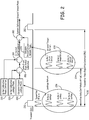
- Figure 2 is a process flow and timing diagram depicting the method for phase calibrating that can be used in the radar system.
- the radar system is initially calibrated during production at room temperature and nominal environmental conditions to determine an initial calibration phase correction (block 210) and an initial calibration leakage phase (block 220) for each receive antenna, which are stored in a memory unit of the radar system.
- the transmitter sends an RF pulse having a leakage pulse 236 that is received by each receive antenna and measured in each receiver channel (e.g ., Rx Rcv 1, 2, ...N).
- a present leakage phase for each receiver channel is calculated (block 240) from the measured leakage pulse.
- the present leakage phase (240) for each channel is offset from the initial calibration leakage phase (220) to obtain the delta phase from initial calibration for each channel at 250.
- the delta phase from initial calibration (250) is then offset from the initial calibration phase correction (210) to obtain a corrected initial calibration at 260 for each receiver channel.
- a present ground return phase for each receiver channel is calculated (block 270) from a ground target return signal 238 received by each receive antenna and corresponding receiver channels (e.g., Rx Rcv 1, 2, ... N).
- the corrected initial calibration (260) is combined with the ground return phase (270) to obtain a system calibrated ground return phase at 280 for each receiver channel, which provides the corrected phase value that is used in further processing of data such as to determine cross-track angles.
- the method shown in Figure 2 can be periodically repeated at different intervals, such as at a subsequent transmit gate 282.
- the periodic repetition of the present method can be done for every transmit gate or at other predetermined intervals.
- an automated timer can be utilized at predetermined intervals to implement the method.
- one or more thermocouples can be employed to control how often the leakage pulse is measured such that when the temperature deviates by a certain amount, the method is automatically initiated.
- Instructions for carrying out the various process tasks, calculations, and generation of signals and other data used in the operation of the methods and systems of the invention can be implemented in software, firmware, or other computer readable instructions. These instructions are typically stored on any appropriate computer readable medium used for storage of computer readable instructions or data structures. Such computer readable media can be any available media that can be accessed by a general purpose or special purpose computer or processor, or any programmable logic device.
- Suitable computer readable media may comprise, for example, non-volatile memory devices including semiconductor memory devices such as EPROM, EEPROM, or flash memory devices; magnetic disks such as internal hard disks or removable disks; magneto-optical disks; CDs, DVDs, or other optical storage disks; nonvolatile ROM, RAM, and other like media; or any other media that can be used to carry or store desired program code means in the form of computer executable instructions or data structures. Any of the foregoing may be supplemented by, or incorporated in, specially-designed application-specific integrated circuits (ASICs).
- ASICs application-specific integrated circuits
- the method of the invention can be implemented in computer readable instructions, such as program modules or applications, which are executed by a data processor.
- program modules or applications include routines, programs, objects, data components, data structures, algorithms, etc. that perform particular tasks or implement particular abstract data types.
- program code means for executing steps of the methods disclosed herein.
- the particular sequence of such executable instructions or associated data structures represent examples of corresponding acts for implementing the functions described in such steps.
Landscapes
- Engineering & Computer Science (AREA)
- Remote Sensing (AREA)
- Radar, Positioning & Navigation (AREA)
- Physics & Mathematics (AREA)
- Computer Networks & Wireless Communication (AREA)
- General Physics & Mathematics (AREA)
- Electromagnetism (AREA)
- Radar Systems Or Details Thereof (AREA)
Claims (10)
- Procédé de calibrage en phase d'antennes dans un système radar, le procédé comprenant les étapes suivantes :(a) utilisation d'une antenne d'émission et d'au moins deux antennes de réception, les antennes de réception étant chacune en communication avec un canal de récepteur respectif ;(b) détermination d'une correction de phase de calibrage initial pour chacune des antennes de réception ;(c) détermination d'une phase de fuite de calibrage initial pour chacune des antennes de réception ;(d) émission d'une impulsion radiofréquence comportant une impulsion de fuite reçue par chaque antenne de réception et mesurée dans chaque canal de récepteur ;(e) calcul d'une phase de fuite présente pour chaque canal de récepteur à partir de l'impulsion de fuite ;(f) décalage de la phase de fuite présente par rapport à la phase de fuite de calibrage initial aux fins d'obtenir un déphasage delta par rapport au calibrage initial pour chaque canal de récepteur ;(g) décalage du déphasage delta par rapport au calibrage initial par rapport à la correction de phase de calibrage initial aux fins d'obtenir un calibrage initial corrigé pour chaque canal de récepteur ;(h) calcul d'une phase d'écho de sol pour chaque canal de récepteur à partir d'un signal d'écho de cible au sol reçu par chaque antenne de réception ; et(i) combinaison du calibrage initial corrigé et de la phase d'écho de sol aux fins d'obtenir une phase d'écho de sol calibrée de système pour chaque canal de récepteur.
- Procédé selon la revendication 1, dans lequel le système radar comprend un système radar pulsé.
- Procédé selon la revendication 1, dans lequel les antennes d'émission et de réception sont assujetties à un aéronef.
- Procédé selon la revendication 3, dans lequel les étapes (d) à (i) ont lieu au cours d'un intervalle de répétition des impulsions d'émetteur tandis que l'aéronef est en vol.
- Procédé selon la revendication 4, comprenant en outre l'étape de répétition périodique des étapes (d) à (i) aux fins de mesurer des variations de phase relative entre chaque canal de récepteur au cours d'un ou de plusieurs intervalles de répétition des impulsions d'émetteur ultérieurs.
- Procédé selon la revendication 1, dans lequel la correction de phase de calibrage initial et la phase de fuite de calibrage initial sont enregistrées dans une unité de mémoire du système radar.
- Procédé selon la revendication 1, dans lequel la correction de phase de calibrage initial et la phase de fuite de calibrage initial sont déterminées à la température du local et dans des conditions ambiantes nominales.
- Procédé selon la revendication 1, dans lequel la phase d'écho de sol calibrée de système produit une valeur de phase corrigée pour chaque canal de récepteur.
- Procédé selon la revendication 8, comprenant en outre l'étape de détermination d'un angle transversal à la trace pour chaque canal de récepteur à partir de la valeur de phase corrigée pour chaque canal de récepteur.
- Procédé selon la revendication 1, dans lequel l'impulsion radiofréquence est émise au cours d'un créneau d'émission d'un intervalle de répétition des impulsions d'émetteur.
Applications Claiming Priority (1)
| Application Number | Priority Date | Filing Date | Title |
|---|---|---|---|
| US11/697,970 US7522096B2 (en) | 2007-04-09 | 2007-04-09 | Method for phase calibrating antennas in a radar system |
Publications (2)
| Publication Number | Publication Date |
|---|---|
| EP1981120A1 EP1981120A1 (fr) | 2008-10-15 |
| EP1981120B1 true EP1981120B1 (fr) | 2017-10-25 |
Family
ID=39495588
Family Applications (1)
| Application Number | Title | Priority Date | Filing Date |
|---|---|---|---|
| EP08103417.5A Ceased EP1981120B1 (fr) | 2007-04-09 | 2008-04-07 | Procédé d'étalonnage de phase d'antennes dans un système de radar |
Country Status (2)
| Country | Link |
|---|---|
| US (1) | US7522096B2 (fr) |
| EP (1) | EP1981120B1 (fr) |
Families Citing this family (22)
| Publication number | Priority date | Publication date | Assignee | Title |
|---|---|---|---|---|
| US7522096B2 (en) * | 2007-04-09 | 2009-04-21 | Honeywell International Inc | Method for phase calibrating antennas in a radar system |
| US8358239B2 (en) | 2010-04-01 | 2013-01-22 | Massachusetts Institute Of Technology | Iterative clutter calibration with phased array antennas |
| US8692707B2 (en) | 2011-10-06 | 2014-04-08 | Toyota Motor Engineering & Manufacturing North America, Inc. | Calibration method for automotive radar using phased array |
| US8866667B2 (en) | 2012-02-22 | 2014-10-21 | Honeywell International Inc. | High sensitivity single antenna FMCW radar |
| US9856859B2 (en) | 2012-06-26 | 2018-01-02 | Vestas Wind Systems A/S | Wind turbine blade vibration detection and radar calibration |
| US9297885B2 (en) | 2012-07-27 | 2016-03-29 | Honeywell International Inc. | Method of system compensation to reduce the effects of self interference in frequency modulated continuous wave altimeter systems |
| US9170320B1 (en) * | 2012-12-03 | 2015-10-27 | Lockheed Martin Corporation | Transmitter pushing compensation for radar stability enhancement |
| US9702928B2 (en) | 2014-01-15 | 2017-07-11 | The Boeing Company | Self-healing array system and method |
| DE102014106892B3 (de) * | 2014-05-15 | 2015-10-22 | Deutsches Zentrum für Luft- und Raumfahrt e.V. | Inverses Synthetisches Apertur Radar (ISAR) und Verfahren zur Erfassung von Verunreinigungen in einem Material |
| US9660605B2 (en) | 2014-06-12 | 2017-05-23 | Honeywell International Inc. | Variable delay line using variable capacitors in a maximally flat time delay filter |
| US10018716B2 (en) | 2014-06-26 | 2018-07-10 | Honeywell International Inc. | Systems and methods for calibration and optimization of frequency modulated continuous wave radar altimeters using adjustable self-interference cancellation |
| KR102422396B1 (ko) * | 2015-09-01 | 2022-07-20 | 주식회사 에이치엘클레무브 | 선형 위상 어레이 안테나의 공간 보간 방법 및 보간 장치 |
| US10756428B2 (en) | 2017-02-13 | 2020-08-25 | General Dynamics Mission Systems, Inc. | Systems and methods for inertial navigation system to RF line-of sight alignment calibration |
| US10830872B2 (en) | 2018-06-07 | 2020-11-10 | Fca Us Llc | Vehicle multi-radar relative phase interferometry alignment systems and methods |
| WO2020017290A1 (fr) * | 2018-07-20 | 2020-01-23 | 京セラ株式会社 | Dispositif électronique, procédé de commande de dispositif électronique et programme de commande de dispositif électronique |
| CN108776330B (zh) * | 2018-08-17 | 2020-02-07 | 湖南时变通讯科技有限公司 | 一种fmcw雷达多接收通道的高精度校准方法和装置 |
| CN109856603B (zh) * | 2019-03-26 | 2021-12-28 | 森思泰克河北科技有限公司 | 雷达抗干扰方法、终端设备及存储介质 |
| US11482779B2 (en) | 2019-07-12 | 2022-10-25 | Raytheon Company | Minimal phase matched test target injection for parallel receiver phase and amplitude alignment |
| US11294050B2 (en) | 2020-01-15 | 2022-04-05 | Rockwell Collins, Inc. | Automatic ground initialization of radar alignment servo |
| JP7308454B2 (ja) * | 2020-03-23 | 2023-07-14 | パナソニックIpマネジメント株式会社 | レーダ装置 |
| CN112180351B (zh) * | 2020-09-22 | 2023-07-14 | 中国科学院空天信息创新研究院 | 相位补偿方法、装置、设备及计算机存储介质 |
| DE102021106428B4 (de) * | 2021-03-16 | 2023-08-24 | Infineon Technologies Ag | End-of-line-phasenkalibrierung von radareinrichtungen |
Family Cites Families (18)
| Publication number | Priority date | Publication date | Assignee | Title |
|---|---|---|---|---|
| JPH0785543B2 (ja) * | 1988-02-22 | 1995-09-13 | 三菱電機株式会社 | 送受信モジュール点検確認装置 |
| US5160933A (en) | 1990-08-28 | 1992-11-03 | Honeywell Inc. | Radar altimeter with self-calibration feature |
| US5253188A (en) * | 1991-04-19 | 1993-10-12 | Hughes Aircraft Company | Built-in system for antenna calibration, performance monitoring and fault isolation of phased array antenna using signal injections and RF switches |
| JPH0815420A (ja) | 1994-06-27 | 1996-01-19 | Japan Aviation Electron Ind Ltd | 電波距離計 |
| NL9500580A (nl) * | 1995-03-27 | 1996-11-01 | Hollandse Signaalapparaten Bv | Phased array antenne voorzien van een calibratienetwerk. |
| US5559519A (en) * | 1995-05-04 | 1996-09-24 | Northrop Grumman Corporation | Method and system for the sequential adaptive deterministic calibration of active phased arrays |
| US5682165A (en) * | 1996-05-02 | 1997-10-28 | Hughes Electronics | Active array self calibration |
| SE509434C2 (sv) * | 1997-05-16 | 1999-01-25 | Ericsson Telefon Ab L M | Anordning och förfarande vid antennkalibrering |
| US6208287B1 (en) * | 1998-03-16 | 2001-03-27 | Raytheoncompany | Phased array antenna calibration system and method |
| SE515141C2 (sv) * | 2000-03-22 | 2001-06-18 | Ericsson Telefon Ab L M | Självkalibrering av matarledningar för gruppantenner |
| US20030030582A1 (en) * | 2001-08-10 | 2003-02-13 | Vickers Roger S. | Environment measurement methods, systems, media, signals and data structures |
| DE10227822A1 (de) | 2002-06-21 | 2004-01-08 | Robert Bosch Gmbh | Verfahren und Vorrichtung zum Kalibrieren einer HF-Einrichtung |
| DE10238213A1 (de) | 2002-08-21 | 2004-03-04 | Robert Bosch Gmbh | Online Kalibrierung eines Radarsensors mit Gruppenantenne |
| JP2006003097A (ja) * | 2004-06-15 | 2006-01-05 | Fujitsu Ten Ltd | レーダ装置 |
| US7138940B2 (en) * | 2004-07-22 | 2006-11-21 | Honeywell International Inc. | Method and systems for automatic zero calibration of radar altimeters |
| US7161530B2 (en) * | 2005-02-22 | 2007-01-09 | The United States Of America As Represented By The Secretary Of The Army | System and method for radar calibration using antenna leakage |
| US7408507B1 (en) * | 2005-03-15 | 2008-08-05 | The United States Of America As Represented By The Secretary Of The Navy | Antenna calibration method and system |
| US7522096B2 (en) * | 2007-04-09 | 2009-04-21 | Honeywell International Inc | Method for phase calibrating antennas in a radar system |
-
2007
- 2007-04-09 US US11/697,970 patent/US7522096B2/en active Active
-
2008
- 2008-04-07 EP EP08103417.5A patent/EP1981120B1/fr not_active Ceased
Non-Patent Citations (1)
| Title |
|---|
| None * |
Also Published As
| Publication number | Publication date |
|---|---|
| US20080246649A1 (en) | 2008-10-09 |
| EP1981120A1 (fr) | 2008-10-15 |
| US7522096B2 (en) | 2009-04-21 |
Similar Documents
| Publication | Publication Date | Title |
|---|---|---|
| EP1981120B1 (fr) | Procédé d'étalonnage de phase d'antennes dans un système de radar | |
| US9547072B2 (en) | Weather radar | |
| US7358892B2 (en) | System and method for coherently combining a plurality of radars | |
| US10018715B2 (en) | Radar sensor for motor vehicles | |
| CN108776330B (zh) | 一种fmcw雷达多接收通道的高精度校准方法和装置 | |
| US7576686B2 (en) | Method and system for calibrating an antenna array for an aircraft surveillance system | |
| US20150035697A1 (en) | Radar calibration system for vehicles | |
| US11940554B2 (en) | Automotive radar arrangement and method for object detection by vehicle radar | |
| US9673846B2 (en) | Temperature compensation system and method for an array antenna system | |
| US20070194982A1 (en) | Antenna signal processing apparatus | |
| EP1818683B1 (fr) | Procédés et systèmes pour l'étalonnage de phase interférométrique d'écart de route | |
| CN111190183A (zh) | 用于雷达系统中目标检测的滑动窗口积分方案 | |
| US10921427B2 (en) | Drone-based calibration of a phased array radar | |
| Jirousek et al. | Development of the highly accurate DLR Kalibri transponder | |
| US7925251B2 (en) | Automatic delay calibration and tracking for ultra-wideband antenna array | |
| EP0027122B1 (fr) | Radar a mono-impulsions avec generateur de signaux pilotes | |
| US20180136313A1 (en) | Calibration device and calibration method for calibrating antenna arrays | |
| US20250035767A1 (en) | Positioning system and vehicle including positioning system, and positioning method | |
| US20240319334A1 (en) | Phase error compensation device and method of radar, and radar device including the same | |
| Fornari et al. | CryoSat: Siral calibration and performance | |
| CN116148784B (zh) | 一种单站闪电定位系统相位自动校准系统及方法 | |
| KR102827818B1 (ko) | 위상배열 송수신 시스템의 위상 보정 제어 방법 및 그를 위한 장치 | |
| CN110596658A (zh) | 一种自动测量鞭状线性天线阵列位置的校正终端 | |
| US7486228B2 (en) | Methods and systems for piecewise curve fitting or radar altimeter range gate data | |
| Döring et al. | Highly accurate calibration target for multiple mode SAR systems |
Legal Events
| Date | Code | Title | Description |
|---|---|---|---|
| PUAI | Public reference made under article 153(3) epc to a published international application that has entered the european phase |
Free format text: ORIGINAL CODE: 0009012 |
|
| 17P | Request for examination filed |
Effective date: 20080407 |
|
| AK | Designated contracting states |
Kind code of ref document: A1 Designated state(s): AT BE BG CH CY CZ DE DK EE ES FI FR GB GR HR HU IE IS IT LI LT LU LV MC MT NL NO PL PT RO SE SI SK TR |
|
| AX | Request for extension of the european patent |
Extension state: AL BA MK RS |
|
| 17Q | First examination report despatched |
Effective date: 20081112 |
|
| AKX | Designation fees paid |
Designated state(s): DE FR GB IT |
|
| RAP1 | Party data changed (applicant data changed or rights of an application transferred) |
Owner name: HONEYWELL INTERNATIONAL INC. |
|
| GRAP | Despatch of communication of intention to grant a patent |
Free format text: ORIGINAL CODE: EPIDOSNIGR1 |
|
| INTG | Intention to grant announced |
Effective date: 20170613 |
|
| GRAS | Grant fee paid |
Free format text: ORIGINAL CODE: EPIDOSNIGR3 |
|
| GRAA | (expected) grant |
Free format text: ORIGINAL CODE: 0009210 |
|
| AK | Designated contracting states |
Kind code of ref document: B1 Designated state(s): DE FR GB IT |
|
| REG | Reference to a national code |
Ref country code: GB Ref legal event code: FG4D |
|
| REG | Reference to a national code |
Ref country code: DE Ref legal event code: R096 Ref document number: 602008052614 Country of ref document: DE |
|
| REG | Reference to a national code |
Ref country code: FR Ref legal event code: PLFP Year of fee payment: 11 |
|
| REG | Reference to a national code |
Ref country code: DE Ref legal event code: R097 Ref document number: 602008052614 Country of ref document: DE |
|
| PGFP | Annual fee paid to national office [announced via postgrant information from national office to epo] |
Ref country code: IT Payment date: 20180420 Year of fee payment: 11 Ref country code: FR Payment date: 20180426 Year of fee payment: 11 |
|
| PLBE | No opposition filed within time limit |
Free format text: ORIGINAL CODE: 0009261 |
|
| STAA | Information on the status of an ep patent application or granted ep patent |
Free format text: STATUS: NO OPPOSITION FILED WITHIN TIME LIMIT |
|
| 26N | No opposition filed |
Effective date: 20180726 |
|
| PGFP | Annual fee paid to national office [announced via postgrant information from national office to epo] |
Ref country code: GB Payment date: 20180427 Year of fee payment: 11 Ref country code: DE Payment date: 20180629 Year of fee payment: 11 |
|
| REG | Reference to a national code |
Ref country code: DE Ref legal event code: R119 Ref document number: 602008052614 Country of ref document: DE |
|
| GBPC | Gb: european patent ceased through non-payment of renewal fee |
Effective date: 20190407 |
|
| PG25 | Lapsed in a contracting state [announced via postgrant information from national office to epo] |
Ref country code: GB Free format text: LAPSE BECAUSE OF NON-PAYMENT OF DUE FEES Effective date: 20190407 Ref country code: DE Free format text: LAPSE BECAUSE OF NON-PAYMENT OF DUE FEES Effective date: 20191101 |
|
| PG25 | Lapsed in a contracting state [announced via postgrant information from national office to epo] |
Ref country code: FR Free format text: LAPSE BECAUSE OF NON-PAYMENT OF DUE FEES Effective date: 20190430 |
|
| PG25 | Lapsed in a contracting state [announced via postgrant information from national office to epo] |
Ref country code: IT Free format text: LAPSE BECAUSE OF NON-PAYMENT OF DUE FEES Effective date: 20190407 |
|
| P01 | Opt-out of the competence of the unified patent court (upc) registered |
Effective date: 20230525 |