EP1980775A2 - Miniflow valve - Google Patents
Miniflow valve Download PDFInfo
- Publication number
- EP1980775A2 EP1980775A2 EP20080007035 EP08007035A EP1980775A2 EP 1980775 A2 EP1980775 A2 EP 1980775A2 EP 20080007035 EP20080007035 EP 20080007035 EP 08007035 A EP08007035 A EP 08007035A EP 1980775 A2 EP1980775 A2 EP 1980775A2
- Authority
- EP
- European Patent Office
- Prior art keywords
- valve
- miniflow
- diaphragm
- pressure
- liquid
- Prior art date
- Legal status (The legal status is an assumption and is not a legal conclusion. Google has not performed a legal analysis and makes no representation as to the accuracy of the status listed.)
- Withdrawn
Links
- 239000007788 liquid Substances 0.000 claims abstract description 29
- 238000009434 installation Methods 0.000 claims description 9
- 229910001220 stainless steel Inorganic materials 0.000 claims description 4
- 239000010935 stainless steel Substances 0.000 claims description 4
- 239000012530 fluid Substances 0.000 abstract description 50
- XLYOFNOQVPJJNP-UHFFFAOYSA-N water Substances O XLYOFNOQVPJJNP-UHFFFAOYSA-N 0.000 description 29
- 230000033228 biological regulation Effects 0.000 description 8
- 230000007423 decrease Effects 0.000 description 2
- 230000003247 decreasing effect Effects 0.000 description 2
- 230000002159 abnormal effect Effects 0.000 description 1
- 230000003466 anti-cipated effect Effects 0.000 description 1
- 238000005192 partition Methods 0.000 description 1
- 230000002093 peripheral effect Effects 0.000 description 1
- 230000000717 retained effect Effects 0.000 description 1
Images



Classifications
-
- F—MECHANICAL ENGINEERING; LIGHTING; HEATING; WEAPONS; BLASTING
- F04—POSITIVE - DISPLACEMENT MACHINES FOR LIQUIDS; PUMPS FOR LIQUIDS OR ELASTIC FLUIDS
- F04B—POSITIVE-DISPLACEMENT MACHINES FOR LIQUIDS; PUMPS
- F04B49/00—Control, e.g. of pump delivery, or pump pressure of, or safety measures for, machines, pumps, or pumping installations, not otherwise provided for, or of interest apart from, groups F04B1/00 - F04B47/00
- F04B49/02—Stopping, starting, unloading or idling control
- F04B49/03—Stopping, starting, unloading or idling control by means of valves
-
- F—MECHANICAL ENGINEERING; LIGHTING; HEATING; WEAPONS; BLASTING
- F04—POSITIVE - DISPLACEMENT MACHINES FOR LIQUIDS; PUMPS FOR LIQUIDS OR ELASTIC FLUIDS
- F04B—POSITIVE-DISPLACEMENT MACHINES FOR LIQUIDS; PUMPS
- F04B49/00—Control, e.g. of pump delivery, or pump pressure of, or safety measures for, machines, pumps, or pumping installations, not otherwise provided for, or of interest apart from, groups F04B1/00 - F04B47/00
- F04B49/10—Other safety measures
-
- F—MECHANICAL ENGINEERING; LIGHTING; HEATING; WEAPONS; BLASTING
- F16—ENGINEERING ELEMENTS AND UNITS; GENERAL MEASURES FOR PRODUCING AND MAINTAINING EFFECTIVE FUNCTIONING OF MACHINES OR INSTALLATIONS; THERMAL INSULATION IN GENERAL
- F16K—VALVES; TAPS; COCKS; ACTUATING-FLOATS; DEVICES FOR VENTING OR AERATING
- F16K31/00—Actuating devices; Operating means; Releasing devices
- F16K31/12—Actuating devices; Operating means; Releasing devices actuated by fluid
- F16K31/122—Actuating devices; Operating means; Releasing devices actuated by fluid the fluid acting on a piston
- F16K31/1223—Actuating devices; Operating means; Releasing devices actuated by fluid the fluid acting on a piston one side of the piston being acted upon by the circulating fluid
-
- Y—GENERAL TAGGING OF NEW TECHNOLOGICAL DEVELOPMENTS; GENERAL TAGGING OF CROSS-SECTIONAL TECHNOLOGIES SPANNING OVER SEVERAL SECTIONS OF THE IPC; TECHNICAL SUBJECTS COVERED BY FORMER USPC CROSS-REFERENCE ART COLLECTIONS [XRACs] AND DIGESTS
- Y10—TECHNICAL SUBJECTS COVERED BY FORMER USPC
- Y10T—TECHNICAL SUBJECTS COVERED BY FORMER US CLASSIFICATION
- Y10T137/00—Fluid handling
- Y10T137/7722—Line condition change responsive valves
- Y10T137/7837—Direct response valves [i.e., check valve type]
- Y10T137/7838—Plural
- Y10T137/7842—Diverse types
Definitions
- the present invention relates to a miniflow valve which is disposed in a miniflow line that serves to ensure a minimum flowrate for protecting a pump feeding a liquid under pressure.
- Pumps such as a centrifugal pump are often used in order to feed water or the like liquid under pressure. If, in a case where a predetermined discharge flowrate cannot be ensured, for example, in a case where the discharge side of the pump is closed up, the pump is continued to run as it is, there will occur the drawback that the liquid circulates within the pump to undergo an abnormal temperature rise.
- a miniflow line is laid between the discharge side and suction side of the pump.
- the miniflow line is configured of a bypass pipe which connects the discharge side and suction side of the pump, and a miniflow valve which is disposed in the bypass pipe.
- the miniflow valve is opened to bypass the liquid from the discharge side onto the suction side of the pump, whereby a minimum flowrate (miniflow) for pump protection is ensured.
- Patent Document 1 An apparatus which applies such a miniflow line is a control device for a minimum-flowrate bypass valve as stated in Japanese Unexamined Patent Application, Publication No. Hei 7-208346 (hereinafter referred to as "Patent Document 1").
- the minimum-flowrate bypass valve disclosed in the document is controlled by a control circuit which performs a calculation by obtaining the output signal of a flowrate meter disposed on the discharge side of the pump and the output signal of the drive current of a motor for driving the pump.
- the control device for the minimum-flowrate bypass valve as stated in Patent Document 1 needs to include the control circuit which performs the calculation by obtaining the output signal of the flowrate meter, etc. Therefore, the configuration of the apparatus becomes complicated due to signal wiring, etc., and reduction in the cost thereof is hampered. Besides, in a case where the apparatus is employed for a comparatively large-scale plant, it is sufficiently payable in spite of the introduction of such a control circuit, but in an installation which adopts a small-sized pump having an output lower than, for example, 100 m 3 /h, a system including any electrical control device becomes an excess performance, and hence, actually the introduction is difficult.
- a configuration wherein an orifice being a stationary throttle is disposed in a miniflow line so as to always bypass a partial flowrate irrespective of the discharge flowrate of the pump has been adopted as the miniflow line which does not include any electrical control device.
- the wasteful flowrate is always kept flowing through the bypass line even at the time of rating, so that a running cost increases.
- a pump having a rated flowrate in which the bypass flowrate is added is inevitably selected, and a small pump cannot be selected, so that an installation cost increases.
- a safety valve or an automatic pressure regulation valve which operates at or above a predetermined discharge pressure, instead of the orifice disposed in the miniflow line. Since, however, the safety valve or the automatic pressure regulation valve is configured so as to be opened directly by the discharge pressure of the liquid, a valve opening timing cannot be set at a high precision.
- JIS Japanese Industrial Standard
- a precision of within ⁇ 5% is stipulated, but it is unsatisfactory as the precision required of the miniflow valve. The reasons therefor will be described with reference to FIG. 6 .
- the figure is a graph showing the characteristic of a typical centrifugal pump, and the axis of abscissas represents a flowrate Q (m 3 /h), while the axis of ordinates represents a head H (m).
- the characteristic of the centrifugal pump becomes a curve in a shape lying down, and especially at a small flowrate, the change of the head is small versus that of the flowrate. Accordingly, the set opening degree of the miniflow valve needs to be set at the upper maximum error of the miniflow valve in order that the miniflow valve may be reliably opened at a head H1 corresponding to a minimum flowrate Q1 for pump protection.
- the set opening degree corresponds to a flowrate Q2 being much larger than the minimum flowrate Q1, and the miniflow valve is opened at the large flowrate Q2. Consequently, the rated running point of the centrifugal pump is inevitably set at a flowrate Q3 larger than the flowrate Q2, in other words, at a head H3 smaller than a head H2. That is, there is the problem that the rated running point is inevitably set at the low head in the miniflow valve of low precision.
- the safety valve or the automatic pressure regulation valve is opened by only the discharge side pressure of the pump. Therefore, in a case where the pressure of the discharge side of the pump has fluctuated greatly for any reason, there is anticipated the drawback that the miniflow valve will be unintentionally opened.
- the present invention has been made in view of such circumstances, and it has for its object to provide a miniflow valve which has a simple configuration and which can be opened and closed at a high precision.
- the miniflow valve of the invention adopts means to be stated below.
- the invention provides a miniflow valve which is disposed in a bypass pipe that is connected between a discharge side and a suction side of a main pipe where a liquid fed under pressure by a pump circulates, and which is opened when a head of the pump has exceeded a predetermined value, thereby to return the liquid from the discharge side onto the suction side through the bypass pipe, including a pilot valve which is opened and closed on the basis of a differential pressure between a discharge side pressure and a suction side pressure of the liquid, and a main valve which is opened and closed in accordance with opening and closing operations of the pilot valve.
- the opening and closure of the main valve are determined by the pilot valve which is opened and closed by the differential pressure between the discharge side pressure and suction side pressure of the liquid, so that the differential pressure at which the miniflow valve works can be adjusted at a high precision. Accordingly, the precision can be made remarkably higher as compared with that of a safety valve or an automatic pressure regulation valve which is directly driven by the pressure of the liquid discharged from the pump.
- the pilot valve includes a diaphragm that is deformed when the differential pressure has exceeded the predetermined value, whereby the liquid is caused to flow onto a side of the main valve; and the main valve is opened by a pressure of the liquid led by the diaphragm.
- the main valve is configured so as to be opened by the pressure of the liquid led by the diaphragm, whereby the miniflow valve operates by itself in a mechanical scheme. Accordingly, an electric control need not be performed using an output signal from a flowrate sensor or a pressure sensor, so that the miniflow valve can be provided inexpensively with the simple configuration.
- the pilot valve and the main valve may well be arranged in a common housing.
- the miniflow valve can be configured into a compact structure by arranging the pilot valve and the main valve in the common housing in this manner.
- the miniflow valve of the invention may well include a diaphragm receiver piece which abuts on one side of the diaphragm; wherein the diaphragm receiver piece is urged onto the side of the diaphragm by an elastic member.
- the diaphragm receiver piece is urged onto the side of the diaphragm by the elastic member, whereby the differential pressure at which the diaphragm operates can be set.
- a coiled spring for example, can be employed as the elastic member.
- the miniflow valve of the invention is characterized in that an urging force based on the elastic member is adjustable by altering an installation length of the elastic member.
- the installation position of the spring receiver which receives one end of the coiled spring being the elastic member is altered by an adjustment screw or the like, whereby the installation length of the coiled spring can be altered.
- the urging force based on the elastic member is made adjustable by altering the installation length of the elastic member in this way, so that the working differential pressure of the pilot valve can be finely adjusted.
- the elastic member may well be replaceable.
- the elastic member is made replaceable, whereby it can be altered to an elastic member having a different elastic force.
- the force urging the diaphragm can be altered, so that the differential pressure at which the pilot valve works can be set in a wide range.
- the miniflow valve of the invention may well adopt a wafer connection structure in which the miniflow valve proper is connected with both its sides held by flanges that are disposed in the bypass pipe.
- the miniflow valve can be connected without depending upon the rating of the flanges of the bypass pipe.
- the miniflow valve proper need not be formed with the flanges, the weight thereof can be decreased, and the miniflow valve can be provided inexpensively.
- liquid-touching parts may well be made of stainless steel.
- the miniflow valve can be employed without depending upon the sort of the liquid.
- the opening and closure of the main valve are determined by the pilot valve which is opened and closed by the differential pressure between the discharge side pressure and suction side pressure of the liquid, so that the miniflow valve whose opening and closure are controllable at a high precision can be provided.
- the pilot valve including the diaphragm which is deformed by the differential pressure and which leads the liquid onto the side of the main valve is adopted, and the main valve is configured so as to be opened by the pressure of the liquid led by the diaphragm, whereby the miniflow valve operates by itself in the mechanical scheme, so that the miniflow valve can be provided inexpensively with the simple configuration.
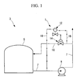
- FIG. 1 shows the schematic configuration of a water supply equipment 3 in which a miniflow valve 1 according to one embodiment of the invention is disposed.
- the water supply equipment 3 includes a feed water tank 5 in which water (a liquid) is stored, a feed water pipe (main pipe) 7 which is extended from the feed water tank 5 to a feed water destination (not shown), and a centrifugal pump 9 which is disposed in the feed water pipe 7, and which pumps up the water in the feed water tank 5 so as to feed the water under pressure toward the feed water destination.
- the centrifugal pump 9 is driven to rotate by a drive motor not shown.
- a miniflow pipe (bypass pipe) 10 is disposed between the feed water pipe 7 on the discharge side of the centrifugal pump 9 and the feed water tank 5.
- the miniflow valve 1 is disposed in the miniflow pipe 10.
- the miniflow valve 1 includes a pilot valve portion 12, and a main valve portion 14.
- a discharge fluid introduction pipe 16 for leading the liquid on the discharge side of the centrifugal pump 9, and a suction fluid introduction pipe 18 for leading a fluid on the suction side of the centrifugal pump 9, are connected to the pilot valve portion 12.
- the valve of the pilot valve portion 12 is opened or closed on the basis of the differential pressure of the fluids led from the introduction pipes 16 and 18, and the valve of the main valve portion 14 is opened or closed correspondingly.
- the pilot valve portion 12 and main valve portion 14 of the miniflow valve 1 are separately shown. However, this illustrates respective functions in model-like fashion, and the pilot valve portion 12 and main valve portion 14 are configured of a unitary housing as will be explained later.
- FIG. 2 A front view of the miniflow valve 1 is shown in FIG. 2 , and vertical sectional views of the miniflow valve 1 are shown in FIGS. 3 and 4 . Besides, FIG. 3 shows the valve closure mode of the miniflow valve 1, while FIG. 4 shows the valve opening mode of the miniflow valve 1.
- the miniflow valve 1 includes the main valve portion 14 which is connected to the miniflow pipe 10, and the pilot valve portion 12 which is connected over the main valve portion 14.
- a main-valve-portion body (housing) 19 which forms the external shape of the main valve portion 14 is provided with an inlet portion 20 into which the water flows from the miniflow pipe 10, and an outlet portion 22 from which the water flows out into the miniflow pipe 10.
- the inlet portion 20 and the outlet portion 22 are disposed in a state where they are juxtaposed in a horizontal direction in FIG. 3 .
- the inlet portion 20 is formed with an inlet chamber 20a, while the outlet portion 22 is formed with an outlet chamber 22a.
- the inlet portion 20 and the outlet portion 22 are respectively shown on a left side and a right side, reversely to those in FIG. 1 .
- a valve rod 24 is arranged on a center axis orthogonal to the horizontal direction in which the inlet portion 20 and the outlet portion 22 are juxtaposed.
- a piston 26 is fixed to the upper end (one end) of the valve rod 24, while a main valve member 28 is fixed to the lower end (the other end) of the valve rod 24.
- the piston 26 is arranged in a piston chamber 27 formed in the upper part of the main-valve-portion body 19, so as to be slidable in the direction of the center axis.
- the main valve member 28 is in a bottomed cylindrical shape, and it is arranged in a state where its bottom 28a faces upward (onto the side of the valve rod 24).
- Part of the main valve member 28 on the side of the recess 28b thereof is accommodated in a recess 30a which is formed in the upper part of a lid 30 that is threadably engaged with the bottom 19a of the main-valve-portion body 19.
- the main valve member 28 reciprocates while sliding relative to the inner surface of the recess 30a, inside the recess 30a of the lid 30.
- a main-valve-member spring 32 is retained in a space which is defined by the recess 28b of the main valve member 28 and the recess 30a of the lid 30.
- the main-valve-member spring 32 is arranged in a state where it has the same axis as that of the valve rod 24, and it urges the main valve member 28 upwards (onto the side of the valve rod 24).
- a valve seat 34 is disposed over the main valve member 28 (on the side of the valve rod 24).
- the valve seat 34 is in a bottomed cylindrical shape, and it is arranged in a state where its bottom 34a faces upwards.
- An aperture 34b is formed centrally of the bottom 34a of the valve seat 34, and the valve rod 24 is inserted through the aperture 34b.
- the open end 34c of the valve seat 34 is snugly fitted into a partition wall 36 which divides the inlet chamber 20a and the outlet chamber 22a.
- a plurality of circulation apertures 34d are formed in the sidewall of the valve seat 34 on the side of the bottom 34a thereof, so as to be spaced in the peripheral direction of the sidewall, and the water flows through the circulation apertures 34d.
- a state (in FIG. 3 ) where the main valve member 28 comes into touch with the valve seat 34 is the valve closure state of the miniflow valve 1
- a state (in FIG. 4 ) where the main valve member 28 comes out of touch with the valve seat 34 is the valve opening state.
- the pilot valve portion 12 has its external shape formed of a first pilot-valve-portion body (housing) 40 which is located on the side of the main valve portion 14, and a second pilot-valve-portion body (housing) 42 which is connected to the first pilot-valve-portion body (housing) 40.
- the first pilot-valve-portion body 40 is arranged between the main-valve-portion body 19 and the second pilot-valve-portion body 42.
- the main-valve-portion body 19, the first pilot-valve-portion body 40 and the second pilot-valve-portion body 42 are unitarily fixed by a plurality of bolts 44.
- the pilot valve portion 12 and the main valve portion 14 are unitarily configured.
- a central aperture 40a having substantially the same axis as that of the valve rod 24 is formed centrally of the first pilot-valve-portion body 40.
- a discharge fluid introduction chamber 40b which is divided by a protrusion 40c is formed around the central aperture 40a. The upper end of the protrusion 40c is abuttable on a diaphragm 41 to be explained later.
- a discharge fluid led from the discharge fluid introduction pipe 16 (refer to FIG. 2 ) is introduced into the discharge fluid introduction chamber 40b through a discharge fluid introduction port 40d.
- the second pilot-valve-portion body 42 has a flange part 42a located below, and a cylindrical part 42b located above.
- the lower end of the flange part 42a (on the side of the first pilot-valve-portion body 40) is provided with a convexity 42c, which is snugly fitted into a concavity formed in the upper end of the first pilot-valve-portion body 40.
- a convexity 42c which is snugly fitted into a concavity formed in the upper end of the first pilot-valve-portion body 40.
- a recess is formed centrally of the lower end of the flange part 42a, and a diaphragm receiver piece 49 is accommodated in the recess.
- the diaphragm receiver piece 49 reciprocates while sliding relative to the inner surface of the recess of the flange part 42a.
- the lower surface of the diaphragm receiver piece 49 abuts on the diaphragm 41.
- a suction fluid introduction chamber 42d is formed in the second pilot-valve-portion body 42 located on the upper surface side of the diaphragm receiver piece 49.
- a suction fluid led from the suction fluid introduction pipe 18 (refer to FIG. 2 ) is introduced into the suction fluid introduction chamber 42d through a suction fluid introduction port 42e.
- An upwardly protruding bulge 49a is formed centrally of the diaphragm receiver piece 49.
- the bulge 49a is accommodated in a central aperture 42f formed centrally of the flange part 42a, from below.
- a bulge 51a formed at the lower part of a lower spring receiver piece 51 is accommodated in the central aperture 42f, from above, and the lower end surface of the bulge 51a abuts on the upper end surface of the bulge 49a of the diaphragm receiver piece 49.
- An adjustment coiled spring 53 having the same axis as that of the diaphragm receiver piece 49 is accommodated in the cylindrical part 42b of the second pilot-valve-portion body 42.
- the lower part of the adjustment coiled spring 53 is supported by the lower spring receiver piece 51, while the upper part of the adjustment coiled spring 53 is supported by an upper spring receiver piece 55.
- An upwardly protruding bulge 55a is formed at the upper part of the upper spring receiver piece 55, and it abuts on the lower end of a regulation screw 57 located above.
- the regulation screw 57 is threadably engaged with the central part of an upper lid 59 which is threadably coupled to the upper end of the cylindrical part 42b.
- the regulation screw 57 is turned to be advanced or retracted in the vertical direction of the miniflow valve 1 relative to the upper lid 59, whereby the installation length of the adjustment coiled spring 53 can be altered.
- the urging force of the adjustment coiled spring 53 can be altered by altering the installation length of the adjustment coiled spring 53 in this manner.
- the adjustment coiled spring 53 can be replaced by detaching the upper lid 59.
- the adjustment coiled spring 53 can be altered to one having a different spring force, thereby to greatly alter the force urging the diaphragm 41, so that the differential pressure at which the pilot valve works can be set in a wide range.
- the liquid-touching parts of the above miniflow valve 1, such as the main-valve-portion body 19, second pilot-valve-portion body 42, diaphragm 41, diaphragm receiver piece 49, piston 26, main valve member 28 and valve seat 34, are made of stainless steel.
- the miniflow valve 1 can be employed without depending upon the sort of the liquid.
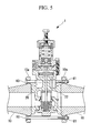
- FIG. 5 shows a state where the miniflow valve 1 is wafer-connected.
- the miniflow pipe 10 is provided with two opposing flanges 10a, between which the miniflow valve 1 is arranged.
- a plurality of long bolts 60 are insertedly passed between both the opposing flanges 10a, and they are fixed by nuts 61 at ends opposite thereto.
- the miniflow valve 1 Owing to the wafer connection in which the miniflow valve 1 is connected in the state where it is held between both its sides in this manner, the miniflow valve 1 can be connected without depending upon the rating of the flanges of the miniflow pipe 10.
- the miniflow valve 1 need not be formed with the flanges, the weight of the miniflow valve 1 proper can be decreased, and the miniflow valve 1 can be provided inexpensively.
- the water stored in the feed water tank 5 is supplied toward the feed water destination through the feed water pipe 7 by the centrifugal pump 9.
- the miniflow valve 1 In a case where the head of the centrifugal pump 9 is the set value of the miniflow valve 1 or less, that is, where the differential pressure between the pressure of the discharge fluid of the centrifugal pump 9 and the pressure of the suction fluid thereof is a set differential pressure or below, the miniflow valve 1 is kept closed, and the water does not flow into the miniflow pipe 10.
- the differential pressure between the pressure of the discharge fluid of the centrifugal pump 9 and the pressure of the suction fluid thereof is obtained in the pilot valve portion 12 of the miniflow valve 1 from the fluids which are led from the discharge fluid introduction pipe 16 and the suction fluid introduction pipe 18.
- the fluid from the discharge fluid introduction pipe 16 is led toward the discharge fluid introduction chamber 40b through the discharge fluid introduction port 40d.
- the fluid from the suction fluid introduction pipe 18 is led toward the suction fluid introduction chamber 42d through the suction fluid introduction port 42e.
- an upward force based on the pressure inside the discharge fluid introduction chamber 40b acts on the diaphragm 41.
- the resultant force of a downward force based on the pressure inside the suction fluid introduction chamber 42d and a downward force from the adjustment coiled spring 53 acts on the diaphragm 41.
- the head of the centrifugal pump 9 is the predetermined value or less, the downward force acting on the diaphragm 41 overcomes the upward force.
- the diaphragm 41 is pressed downwards by the diaphragm receiver piece 49 until it abuts on the upper end of the protrusion 40c. That is, the pilot valve which is configured of the diaphragm 41 and the protrusion 40c is closed.
- the fluid inside the discharge fluid introduction chamber 40b does not flow toward the piston chamber 27 through the central aperture 40a, and hence, a force pressing the piston 26 downwards doe not act on this piston 26.
- the main valve member 28 is fixed to that other end (lower end) of the valve rod 24 to which the piston 26 is fixed, and this main valve member 28 is urged upwards by the main-valve-member spring 32. Accordingly, the main valve member 28 comes into touch with the valve seat 34 and closes up the flow passage, and the fluid in the inlet chamber 20a does not flow toward the outlet chamber 22a.
- the miniflow valve 1 is opened, the water is caused to flow into the miniflow pipe 10 and is returned toward the feed water tank 5.
- the miniflow valve 1 operates as stated below.
- the pressure of the discharge fluid enlarges, and the pressure inside the discharge fluid introduction chamber 40b rises.
- a force pressing the diaphragm 41 upwards increases, and it eventually overcomes the resultant force of the downward force based on the pressure inside the suction fluid introduction chamber 42d and the downward force from the adjustment coiled spring 53 until the diaphragm 41 comes away from the upper end of the protrusion 40c. That is, the pilot valve which is configured of the diaphragm 41 and the protrusion 40c is opened.
- the fluid in the discharge fluid introduction chamber 40b flows into the piston chamber 27 through the central aperture 40a, and a force pressing the piston 26 downwards is exerted on this piston 26.
- the force pressing the piston 26 downwards owing to the pressure based on the discharge fluid overcomes the force with which the main-valve-member spring 32 presses the piston 26 upwards through the main valve member 28 as well as the valve rod 24, so that the piston 26 is pressed downwards.
- the main valve member 28 comes away from the valve seat 34 and forms the flow passage, so that the fluid in the inlet chamber 20a flows into the outlet chamber 22a.
- the upward force acting on the diaphragm 41 becomes smaller than the downward force, and the diaphragm 41 comes into touch with the protrusion 40c.
- the fluid in the discharge fluid introduction chamber 40b is prevented from flowing into the piston chamber 27 through the central aperture 40a, and hence, the force pressing the piston 26 downwards weakens. Accordingly, the piston 26 is pressed upwards by the force of the main-valve-member spring 32, and the main valve member 28 comes into touch with the valve seat 34, thereby to close the valve.
- a pilot valve is configured including a diaphragm 41 which is deformed by the differential pressure between the discharge side pressure and suction side pressure of a centrifugal pump 9, and the opening or closure of a main valve member 28 is determined by the opening or closure of the pilot valve, so that the differential pressure at which a miniflow valve 1 works can be adjusted at a high precision. Accordingly, the precision can be made remarkably higher than that of a safety valve or an automatic pressure regulation valve which is directly driven by the pressure of a fluid discharged from the centrifugal pump 9.
- the miniflow valve 1 in the embodiments is so configured as to adopt the pilot valve including the diaphragm 41 which is deformed by the differential pressure and which leads a fluid into a piston chamber 27, and to open the main valve member 28 by pressing a piston 26 downwards by the pressure of the fluid led from the diaphragm 41, whereby the miniflow valve 1 operates by itself in a mechanical scheme. Accordingly, an electric control need not be performed using an output signal from a flowrate sensor or a pressure sensor, so that the miniflow valve 1 can be provided inexpensively with the simple configuration.
- pilot valve and a main valve are arranged in a common housing by connecting a pilot valve portion 12 and a main valve portion 14, so that the miniflow valve 1 can be configured into a compact structure.
Landscapes
- Engineering & Computer Science (AREA)
- General Engineering & Computer Science (AREA)
- Mechanical Engineering (AREA)
- Safety Valves (AREA)
- Control Of Positive-Displacement Pumps (AREA)
- Structures Of Non-Positive Displacement Pumps (AREA)
- Fluid-Driven Valves (AREA)
- Control Of Non-Positive-Displacement Pumps (AREA)
Abstract
In a miniflow valve which is disposed in a miniflow pipe that is connected between the discharge side and suction side of a main pipe where a liquid fed under pressure by a centrifugal pump circulates, and which is opened when the head of the centrifugal pump has exceeded a predetermined value, thereby to return a fluid from the discharge side onto the suction side through the miniflow pipe; a miniflow valve including a pilot valve which is opened or closed on the basis of the differential pressure between the discharge side pressure and suction side pressure of the liquid, and a main valve which is opened or closed in accordance with the opening or closing operation of the pilot valve. The miniflow valve has the simple configuration, and can be opened or closed at a high precision.
Description
- The present invention relates to a miniflow valve which is disposed in a miniflow line that serves to ensure a minimum flowrate for protecting a pump feeding a liquid under pressure.
- This application is based on Japanese Patent Application No.
2007-106369 - Pumps such as a centrifugal pump are often used in order to feed water or the like liquid under pressure. If, in a case where a predetermined discharge flowrate cannot be ensured, for example, in a case where the discharge side of the pump is closed up, the pump is continued to run as it is, there will occur the drawback that the liquid circulates within the pump to undergo an abnormal temperature rise. In order to avoid such a drawback, a miniflow line is laid between the discharge side and suction side of the pump. The miniflow line is configured of a bypass pipe which connects the discharge side and suction side of the pump, and a miniflow valve which is disposed in the bypass pipe. Owing to the laying of such a miniflow line, in the case where a flowrate on the discharge side of the pump has become the predetermined flowrate or less, the miniflow valve is opened to bypass the liquid from the discharge side onto the suction side of the pump, whereby a minimum flowrate (miniflow) for pump protection is ensured.
- An apparatus which applies such a miniflow line is a control device for a minimum-flowrate bypass valve as stated in Japanese Unexamined Patent Application, Publication No.
Hei 7-208346 Patent Document 1"). The minimum-flowrate bypass valve disclosed in the document is controlled by a control circuit which performs a calculation by obtaining the output signal of a flowrate meter disposed on the discharge side of the pump and the output signal of the drive current of a motor for driving the pump. - The control device for the minimum-flowrate bypass valve as stated in
Patent Document 1 needs to include the control circuit which performs the calculation by obtaining the output signal of the flowrate meter, etc. Therefore, the configuration of the apparatus becomes complicated due to signal wiring, etc., and reduction in the cost thereof is hampered. Besides, in a case where the apparatus is employed for a comparatively large-scale plant, it is sufficiently payable in spite of the introduction of such a control circuit, but in an installation which adopts a small-sized pump having an output lower than, for example, 100 m3/h, a system including any electrical control device becomes an excess performance, and hence, actually the introduction is difficult. - Therefore, a configuration wherein an orifice being a stationary throttle is disposed in a miniflow line so as to always bypass a partial flowrate irrespective of the discharge flowrate of the pump has been adopted as the miniflow line which does not include any electrical control device. With the configuration, however, the wasteful flowrate is always kept flowing through the bypass line even at the time of rating, so that a running cost increases. Further, a pump having a rated flowrate in which the bypass flowrate is added is inevitably selected, and a small pump cannot be selected, so that an installation cost increases.
- On the other hand, it is considered to adopt a safety valve or an automatic pressure regulation valve which operates at or above a predetermined discharge pressure, instead of the orifice disposed in the miniflow line. Since, however, the safety valve or the automatic pressure regulation valve is configured so as to be opened directly by the discharge pressure of the liquid, a valve opening timing cannot be set at a high precision. In accordance with, for example, JIS (Japanese Industrial Standard) concerning safety valves, a precision of within ±5% is stipulated, but it is unsatisfactory as the precision required of the miniflow valve. The reasons therefor will be described with reference to
FIG. 6 . - The figure is a graph showing the characteristic of a typical centrifugal pump, and the axis of abscissas represents a flowrate Q (m3/h), while the axis of ordinates represents a head H (m). As shown in the figure, the characteristic of the centrifugal pump becomes a curve in a shape lying down, and especially at a small flowrate, the change of the head is small versus that of the flowrate. Accordingly, the set opening degree of the miniflow valve needs to be set at the upper maximum error of the miniflow valve in order that the miniflow valve may be reliably opened at a head H1 corresponding to a minimum flowrate Q1 for pump protection. Then, at the lower maximum error of the miniflow valve, the set opening degree corresponds to a flowrate Q2 being much larger than the minimum flowrate Q1, and the miniflow valve is opened at the large flowrate Q2. Consequently, the rated running point of the centrifugal pump is inevitably set at a flowrate Q3 larger than the flowrate Q2, in other words, at a head H3 smaller than a head H2. That is, there is the problem that the rated running point is inevitably set at the low head in the miniflow valve of low precision.
- Further, the safety valve or the automatic pressure regulation valve is opened by only the discharge side pressure of the pump. Therefore, in a case where the pressure of the discharge side of the pump has fluctuated greatly for any reason, there is anticipated the drawback that the miniflow valve will be unintentionally opened.
- The present invention has been made in view of such circumstances, and it has for its object to provide a miniflow valve which has a simple configuration and which can be opened and closed at a high precision.
- In order to solve the problems, the miniflow valve of the invention adopts means to be stated below.
- The invention provides a miniflow valve which is disposed in a bypass pipe that is connected between a discharge side and a suction side of a main pipe where a liquid fed under pressure by a pump circulates, and which is opened when a head of the pump has exceeded a predetermined value, thereby to return the liquid from the discharge side onto the suction side through the bypass pipe, including a pilot valve which is opened and closed on the basis of a differential pressure between a discharge side pressure and a suction side pressure of the liquid, and a main valve which is opened and closed in accordance with opening and closing operations of the pilot valve.
- The opening and closure of the main valve are determined by the pilot valve which is opened and closed by the differential pressure between the discharge side pressure and suction side pressure of the liquid, so that the differential pressure at which the miniflow valve works can be adjusted at a high precision. Accordingly, the precision can be made remarkably higher as compared with that of a safety valve or an automatic pressure regulation valve which is directly driven by the pressure of the liquid discharged from the pump.
- It is also allowed to adopt a configuration in which the pilot valve includes a diaphragm that is deformed when the differential pressure has exceeded the predetermined value, whereby the liquid is caused to flow onto a side of the main valve; and the main valve is opened by a pressure of the liquid led by the diaphragm.
- In this manner, in addition to the pilot valve including the diaphragm which is deformed by the differential pressure and which leads the liquid onto the side of the main valve, the main valve is configured so as to be opened by the pressure of the liquid led by the diaphragm, whereby the miniflow valve operates by itself in a mechanical scheme. Accordingly, an electric control need not be performed using an output signal from a flowrate sensor or a pressure sensor, so that the miniflow valve can be provided inexpensively with the simple configuration.
- The pilot valve and the main valve may well be arranged in a common housing.
- The miniflow valve can be configured into a compact structure by arranging the pilot valve and the main valve in the common housing in this manner.
- The miniflow valve of the invention may well include a diaphragm receiver piece which abuts on one side of the diaphragm; wherein the diaphragm receiver piece is urged onto the side of the diaphragm by an elastic member.
- In this case, the diaphragm receiver piece is urged onto the side of the diaphragm by the elastic member, whereby the differential pressure at which the diaphragm operates can be set. Incidentally, a coiled spring, for example, can be employed as the elastic member.
- The miniflow valve of the invention is characterized in that an urging force based on the elastic member is adjustable by altering an installation length of the elastic member.
- By way of example, the installation position of the spring receiver which receives one end of the coiled spring being the elastic member is altered by an adjustment screw or the like, whereby the installation length of the coiled spring can be altered. The urging force based on the elastic member is made adjustable by altering the installation length of the elastic member in this way, so that the working differential pressure of the pilot valve can be finely adjusted.
- In the miniflow valve of the invention, the elastic member may well be replaceable.
- The elastic member is made replaceable, whereby it can be altered to an elastic member having a different elastic force. Thus, the force urging the diaphragm can be altered, so that the differential pressure at which the pilot valve works can be set in a wide range.
- The miniflow valve of the invention may well adopt a wafer connection structure in which the miniflow valve proper is connected with both its sides held by flanges that are disposed in the bypass pipe.
- Owing to the adoption of the wafer connection in which the miniflow valve proper is connected in the state where both its sides are held by the flanges of the bypass pipe, the miniflow valve can be connected without depending upon the rating of the flanges of the bypass pipe.
- Moreover, since the miniflow valve proper need not be formed with the flanges, the weight thereof can be decreased, and the miniflow valve can be provided inexpensively.
- Further, in the miniflow valve of the invention, liquid-touching parts may well be made of stainless steel.
- Since the liquid-touching parts are made of the stainless steel in this manner, the miniflow valve can be employed without depending upon the sort of the liquid.
- In accordance with the present invention, the opening and closure of the main valve are determined by the pilot valve which is opened and closed by the differential pressure between the discharge side pressure and suction side pressure of the liquid, so that the miniflow valve whose opening and closure are controllable at a high precision can be provided.
- Besides, in the invention, the pilot valve including the diaphragm which is deformed by the differential pressure and which leads the liquid onto the side of the main valve is adopted, and the main valve is configured so as to be opened by the pressure of the liquid led by the diaphragm, whereby the miniflow valve operates by itself in the mechanical scheme, so that the miniflow valve can be provided inexpensively with the simple configuration.
-
-
FIG. 1 is a schematic view showing a water supply equipment in which a miniflow valve according to an embodiment of the present invention is disposed; -
FIG. 2 is a front view showing a miniflow valve according to an embodiment of the invention; -
FIG. 3 is a vertical sectional view showing the valve closure mode of the miniflow valve inFIG. 2 ; -
FIG. 4 is a vertical sectional view showing the valve opening mode of the miniflow valve inFIG. 2 ; -
FIG. 5 is a vertical sectional view showing the wafer connection of the miniflow valve inFIG. 2 ; and -
FIG. 6 is a graph showing the characteristic of a centrifugal pump. - Now, embodiments according to the present invention will be described with reference to the drawings.
-
FIG. 1 shows the schematic configuration of a water supply equipment 3 in which aminiflow valve 1 according to one embodiment of the invention is disposed. - The water supply equipment 3 includes a
feed water tank 5 in which water (a liquid) is stored, a feed water pipe (main pipe) 7 which is extended from thefeed water tank 5 to a feed water destination (not shown), and acentrifugal pump 9 which is disposed in thefeed water pipe 7, and which pumps up the water in thefeed water tank 5 so as to feed the water under pressure toward the feed water destination. - The
centrifugal pump 9 is driven to rotate by a drive motor not shown. - A miniflow pipe (bypass pipe) 10 is disposed between the
feed water pipe 7 on the discharge side of thecentrifugal pump 9 and thefeed water tank 5. Theminiflow valve 1 is disposed in theminiflow pipe 10. - The
miniflow valve 1 includes apilot valve portion 12, and amain valve portion 14. A dischargefluid introduction pipe 16 for leading the liquid on the discharge side of thecentrifugal pump 9, and a suctionfluid introduction pipe 18 for leading a fluid on the suction side of thecentrifugal pump 9, are connected to thepilot valve portion 12. The valve of thepilot valve portion 12 is opened or closed on the basis of the differential pressure of the fluids led from theintroduction pipes main valve portion 14 is opened or closed correspondingly. By the way, inFIG. 1 , thepilot valve portion 12 andmain valve portion 14 of theminiflow valve 1 are separately shown. However, this illustrates respective functions in model-like fashion, and thepilot valve portion 12 andmain valve portion 14 are configured of a unitary housing as will be explained later. - A front view of the
miniflow valve 1 is shown inFIG. 2 , and vertical sectional views of theminiflow valve 1 are shown inFIGS. 3 and4 . Besides,FIG. 3 shows the valve closure mode of theminiflow valve 1, whileFIG. 4 shows the valve opening mode of theminiflow valve 1. - As shown in any of
FIGS. 2 through 4 , theminiflow valve 1 includes themain valve portion 14 which is connected to theminiflow pipe 10, and thepilot valve portion 12 which is connected over themain valve portion 14. - As shown in
FIG. 3 , a main-valve-portion body (housing) 19 which forms the external shape of themain valve portion 14 is provided with aninlet portion 20 into which the water flows from theminiflow pipe 10, and anoutlet portion 22 from which the water flows out into theminiflow pipe 10. Theinlet portion 20 and theoutlet portion 22 are disposed in a state where they are juxtaposed in a horizontal direction inFIG. 3 . Theinlet portion 20 is formed with aninlet chamber 20a, while theoutlet portion 22 is formed with anoutlet chamber 22a. Incidentally, it is to be noted that, in each ofFIGS. 3 and4 , theinlet portion 20 and theoutlet portion 22 are respectively shown on a left side and a right side, reversely to those inFIG. 1 . - In the main-valve-
portion body 19, avalve rod 24 is arranged on a center axis orthogonal to the horizontal direction in which theinlet portion 20 and theoutlet portion 22 are juxtaposed. Apiston 26 is fixed to the upper end (one end) of thevalve rod 24, while amain valve member 28 is fixed to the lower end (the other end) of thevalve rod 24. - The
piston 26 is arranged in apiston chamber 27 formed in the upper part of the main-valve-portion body 19, so as to be slidable in the direction of the center axis. - The
main valve member 28 is in a bottomed cylindrical shape, and it is arranged in a state where its bottom 28a faces upward (onto the side of the valve rod 24). Part of themain valve member 28 on the side of therecess 28b thereof is accommodated in arecess 30a which is formed in the upper part of alid 30 that is threadably engaged with the bottom 19a of the main-valve-portion body 19. Themain valve member 28 reciprocates while sliding relative to the inner surface of therecess 30a, inside therecess 30a of thelid 30. A main-valve-member spring 32 is retained in a space which is defined by therecess 28b of themain valve member 28 and therecess 30a of thelid 30. The main-valve-member spring 32 is arranged in a state where it has the same axis as that of thevalve rod 24, and it urges themain valve member 28 upwards (onto the side of the valve rod 24). - A
valve seat 34 is disposed over the main valve member 28 (on the side of the valve rod 24). Thevalve seat 34 is in a bottomed cylindrical shape, and it is arranged in a state where its bottom 34a faces upwards. Anaperture 34b is formed centrally of the bottom 34a of thevalve seat 34, and thevalve rod 24 is inserted through theaperture 34b. Theopen end 34c of thevalve seat 34 is snugly fitted into apartition wall 36 which divides theinlet chamber 20a and theoutlet chamber 22a. A plurality ofcirculation apertures 34d are formed in the sidewall of thevalve seat 34 on the side of the bottom 34a thereof, so as to be spaced in the peripheral direction of the sidewall, and the water flows through thecirculation apertures 34d. The end face of themain valve member 28 on the side of the bottom 28a thereof comes into and out of touch with the end face of thevalve seat 34 on the side of theopen end 34c thereof. A state (inFIG. 3 ) where themain valve member 28 comes into touch with thevalve seat 34 is the valve closure state of theminiflow valve 1, whereas a state (inFIG. 4 ) where themain valve member 28 comes out of touch with thevalve seat 34 is the valve opening state. - The
pilot valve portion 12 has its external shape formed of a first pilot-valve-portion body (housing) 40 which is located on the side of themain valve portion 14, and a second pilot-valve-portion body (housing) 42 which is connected to the first pilot-valve-portion body (housing) 40. The first pilot-valve-portion body 40 is arranged between the main-valve-portion body 19 and the second pilot-valve-portion body 42. The main-valve-portion body 19, the first pilot-valve-portion body 40 and the second pilot-valve-portion body 42 are unitarily fixed by a plurality ofbolts 44. Thus, thepilot valve portion 12 and themain valve portion 14 are unitarily configured. - A
central aperture 40a having substantially the same axis as that of thevalve rod 24 is formed centrally of the first pilot-valve-portion body 40. A dischargefluid introduction chamber 40b which is divided by aprotrusion 40c is formed around thecentral aperture 40a. The upper end of theprotrusion 40c is abuttable on adiaphragm 41 to be explained later. A discharge fluid led from the discharge fluid introduction pipe 16 (refer toFIG. 2 ) is introduced into the dischargefluid introduction chamber 40b through a dischargefluid introduction port 40d. - The second pilot-valve-
portion body 42 has aflange part 42a located below, and acylindrical part 42b located above. - The lower end of the
flange part 42a (on the side of the first pilot-valve-portion body 40) is provided with aconvexity 42c, which is snugly fitted into a concavity formed in the upper end of the first pilot-valve-portion body 40. In fit-engaging the convexity 42c of theflange part 42a and the first pilot-valve-portion body 40 in this manner, the periphery of thediaphragm 41 is pressed and fixed by theflange part 42a and the first pilot-valve-portion body 40. - A recess is formed centrally of the lower end of the
flange part 42a, and adiaphragm receiver piece 49 is accommodated in the recess. Thediaphragm receiver piece 49 reciprocates while sliding relative to the inner surface of the recess of theflange part 42a. The lower surface of thediaphragm receiver piece 49 abuts on thediaphragm 41. - A suction
fluid introduction chamber 42d is formed in the second pilot-valve-portion body 42 located on the upper surface side of thediaphragm receiver piece 49. A suction fluid led from the suction fluid introduction pipe 18 (refer toFIG. 2 ) is introduced into the suctionfluid introduction chamber 42d through a suctionfluid introduction port 42e. - An upwardly protruding
bulge 49a is formed centrally of thediaphragm receiver piece 49. Thebulge 49a is accommodated in acentral aperture 42f formed centrally of theflange part 42a, from below. Abulge 51a formed at the lower part of a lowerspring receiver piece 51 is accommodated in thecentral aperture 42f, from above, and the lower end surface of thebulge 51a abuts on the upper end surface of thebulge 49a of thediaphragm receiver piece 49. - An adjustment coiled
spring 53 having the same axis as that of thediaphragm receiver piece 49 is accommodated in thecylindrical part 42b of the second pilot-valve-portion body 42. The lower part of the adjustment coiledspring 53 is supported by the lowerspring receiver piece 51, while the upper part of the adjustment coiledspring 53 is supported by an upperspring receiver piece 55. - An upwardly protruding bulge 55a is formed at the upper part of the upper
spring receiver piece 55, and it abuts on the lower end of aregulation screw 57 located above. Theregulation screw 57 is threadably engaged with the central part of anupper lid 59 which is threadably coupled to the upper end of thecylindrical part 42b. Theregulation screw 57 is turned to be advanced or retracted in the vertical direction of theminiflow valve 1 relative to theupper lid 59, whereby the installation length of the adjustment coiledspring 53 can be altered. The urging force of the adjustment coiledspring 53 can be altered by altering the installation length of the adjustment coiledspring 53 in this manner. That is, it is possible to adjust the urging force which is transmitted to thediaphragm 41 through the lowerspring receiver piece 51 as well as thediaphragm receiver piece 49. Accordingly, the operating pressure of thediaphragm 41, namely, the working differential pressure of a pilot valve can be finely adjusted. - The adjustment coiled
spring 53 can be replaced by detaching theupper lid 59. Thus, the adjustment coiledspring 53 can be altered to one having a different spring force, thereby to greatly alter the force urging thediaphragm 41, so that the differential pressure at which the pilot valve works can be set in a wide range. - The liquid-touching parts of the
above miniflow valve 1, such as the main-valve-portion body 19, second pilot-valve-portion body 42,diaphragm 41,diaphragm receiver piece 49,piston 26,main valve member 28 andvalve seat 34, are made of stainless steel. Thus, theminiflow valve 1 can be employed without depending upon the sort of the liquid. -
FIG. 5 shows a state where theminiflow valve 1 is wafer-connected. As shown in the figure, theminiflow pipe 10 is provided with two opposingflanges 10a, between which theminiflow valve 1 is arranged. Concretely, in a state where a flow passage in theminiflow pipe 10 and the flow passages of theinlet portion 20 andoutlet portion 22 of theminiflow valve 1 are arranged so as to coincide, a plurality oflong bolts 60 are insertedly passed between both the opposingflanges 10a, and they are fixed bynuts 61 at ends opposite thereto. - Owing to the wafer connection in which the
miniflow valve 1 is connected in the state where it is held between both its sides in this manner, theminiflow valve 1 can be connected without depending upon the rating of the flanges of theminiflow pipe 10. - Besides, since the
miniflow valve 1 need not be formed with the flanges, the weight of theminiflow valve 1 proper can be decreased, and theminiflow valve 1 can be provided inexpensively. - Next, the operation of the water supply equipment employing the
miniflow valve 1 of the above configuration will be described. - As shown in
FIG. 1 , the water stored in thefeed water tank 5 is supplied toward the feed water destination through thefeed water pipe 7 by thecentrifugal pump 9. - In a case where the head of the
centrifugal pump 9 is the set value of theminiflow valve 1 or less, that is, where the differential pressure between the pressure of the discharge fluid of thecentrifugal pump 9 and the pressure of the suction fluid thereof is a set differential pressure or below, theminiflow valve 1 is kept closed, and the water does not flow into theminiflow pipe 10. The differential pressure between the pressure of the discharge fluid of thecentrifugal pump 9 and the pressure of the suction fluid thereof is obtained in thepilot valve portion 12 of theminiflow valve 1 from the fluids which are led from the dischargefluid introduction pipe 16 and the suctionfluid introduction pipe 18. - Concretely, as shown in
FIG. 3 , the fluid from the dischargefluid introduction pipe 16 is led toward the dischargefluid introduction chamber 40b through the dischargefluid introduction port 40d. The fluid from the suctionfluid introduction pipe 18 is led toward the suctionfluid introduction chamber 42d through the suctionfluid introduction port 42e. On this occasion, an upward force based on the pressure inside the dischargefluid introduction chamber 40b acts on thediaphragm 41. On the other hand, the resultant force of a downward force based on the pressure inside the suctionfluid introduction chamber 42d and a downward force from the adjustment coiledspring 53 acts on thediaphragm 41. In the case where the head of thecentrifugal pump 9 is the predetermined value or less, the downward force acting on thediaphragm 41 overcomes the upward force. Therefore, thediaphragm 41 is pressed downwards by thediaphragm receiver piece 49 until it abuts on the upper end of theprotrusion 40c. That is, the pilot valve which is configured of thediaphragm 41 and theprotrusion 40c is closed. In this case, the fluid inside the dischargefluid introduction chamber 40b does not flow toward thepiston chamber 27 through thecentral aperture 40a, and hence, a force pressing thepiston 26 downwards doe not act on thispiston 26. On the other hand, themain valve member 28 is fixed to that other end (lower end) of thevalve rod 24 to which thepiston 26 is fixed, and thismain valve member 28 is urged upwards by the main-valve-member spring 32. Accordingly, themain valve member 28 comes into touch with thevalve seat 34 and closes up the flow passage, and the fluid in theinlet chamber 20a does not flow toward theoutlet chamber 22a. - Next, a case where the head of the
centrifugal pump 9 has increased will be described. - If, in a case where the feed water destination has been closed up, the running of the
centrifugal pump 9 is continued as it is, a flowrate will decrease, and the head of thecentrifugal pump 9 will increase. In addition, in a case where the head of thecentrifugal pump 9 has exceeded the set value of theminiflow valve 1, that is, where the differential pressure between the discharge fluid and suction fluid of thecentrifugal pump 9 has exceeded the set differential pressure, theminiflow valve 1 is opened, the water is caused to flow into theminiflow pipe 10 and is returned toward thefeed water tank 5. Thus, the minimum flowrate for protecting thecentrifugal pump 9 is ensured. - On this occasion, the
miniflow valve 1 operates as stated below. As shown inFIG. 4 , when the head becomes large, the pressure of the discharge fluid enlarges, and the pressure inside the dischargefluid introduction chamber 40b rises. Thus, a force pressing thediaphragm 41 upwards increases, and it eventually overcomes the resultant force of the downward force based on the pressure inside the suctionfluid introduction chamber 42d and the downward force from the adjustment coiledspring 53 until thediaphragm 41 comes away from the upper end of theprotrusion 40c. That is, the pilot valve which is configured of thediaphragm 41 and theprotrusion 40c is opened. Then, the fluid in the dischargefluid introduction chamber 40b flows into thepiston chamber 27 through thecentral aperture 40a, and a force pressing thepiston 26 downwards is exerted on thispiston 26. The force pressing thepiston 26 downwards owing to the pressure based on the discharge fluid overcomes the force with which the main-valve-member spring 32 presses thepiston 26 upwards through themain valve member 28 as well as thevalve rod 24, so that thepiston 26 is pressed downwards. Thus, themain valve member 28 comes away from thevalve seat 34 and forms the flow passage, so that the fluid in theinlet chamber 20a flows into theoutlet chamber 22a. - Besides, in a case where the head of the
centrifugal pump 9 decreases to become less than the valve-opening set value of theminiflow valve 1, the upward force acting on thediaphragm 41 becomes smaller than the downward force, and thediaphragm 41 comes into touch with theprotrusion 40c. Thus, the fluid in the dischargefluid introduction chamber 40b is prevented from flowing into thepiston chamber 27 through thecentral aperture 40a, and hence, the force pressing thepiston 26 downwards weakens. Accordingly, thepiston 26 is pressed upwards by the force of the main-valve-member spring 32, and themain valve member 28 comes into touch with thevalve seat 34, thereby to close the valve. - As described above, in accordance with the embodiments, advantages to be stated below are attained.
- A pilot valve is configured including a
diaphragm 41 which is deformed by the differential pressure between the discharge side pressure and suction side pressure of acentrifugal pump 9, and the opening or closure of amain valve member 28 is determined by the opening or closure of the pilot valve, so that the differential pressure at which aminiflow valve 1 works can be adjusted at a high precision. Accordingly, the precision can be made remarkably higher than that of a safety valve or an automatic pressure regulation valve which is directly driven by the pressure of a fluid discharged from thecentrifugal pump 9. - Besides, the
miniflow valve 1 in the embodiments is so configured as to adopt the pilot valve including thediaphragm 41 which is deformed by the differential pressure and which leads a fluid into apiston chamber 27, and to open themain valve member 28 by pressing apiston 26 downwards by the pressure of the fluid led from thediaphragm 41, whereby theminiflow valve 1 operates by itself in a mechanical scheme. Accordingly, an electric control need not be performed using an output signal from a flowrate sensor or a pressure sensor, so that theminiflow valve 1 can be provided inexpensively with the simple configuration. - Besides, the pilot valve and a main valve are arranged in a common housing by connecting a
pilot valve portion 12 and amain valve portion 14, so that theminiflow valve 1 can be configured into a compact structure. - By the way, in the embodiments, water has been described as an example of the fluid, the present invention is applicable also in case of another liquid.
Claims (8)
- A miniflow valve which is disposed in a bypass pipe that is connected between a discharge side and a suction side of a main pipe where a liquid fed under pressure by a pump circulates, and which is opened when a head of the pump has exceeded a predetermined value, thereby to return the liquid from the discharge side onto the suction side through the bypass pipe, comprising:a pilot valve which is opened and closed on the basis of a differential pressure between a discharge side pressure and a suction side pressure of the liquid, and a main valve which is opened and closed in accordance with opening and closing operations of the pilot valve.
- A miniflow valve as defined in claim 1, wherein:the pilot valve includes a diaphragm which is deformed when the differential pressure has exceeded the predetermined value, whereby the liquid is caused to flow onto a side of the main valve; andthe main valve is opened by a pressure of the liquid led by the diaphragm.
- A miniflow valve as defined in claim 1, wherein the pilot valve and the main valve are arranged in a common housing.
- A miniflow valve as defined in claim 2, further comprising a diaphragm receiver piece which abuts on one side of the diaphragm;
wherein the diaphragm receiver piece is urged toward the diaphragm by an elastic member. - A miniflow valve as defined in claim 4, wherein an urging force based on the elastic member is adjustable by altering an installation length of the elastic member.
- A miniflow valve as defined in claim 4, wherein the elastic member is replaceable.
- A miniflow valve as defined in claim 1, further comprising a wafer connection structure in which the miniflow valve proper is connected with both its sides held by flanges that are disposed in the bypass pipe.
- A miniflow valve as defined in claim 1, wherein liquid-touching parts are made of stainless steel.
Applications Claiming Priority (1)
| Application Number | Priority Date | Filing Date | Title |
|---|---|---|---|
| JP2007106369A JP4865622B2 (en) | 2007-04-13 | 2007-04-13 | Mini flow valve |
Publications (1)
| Publication Number | Publication Date |
|---|---|
| EP1980775A2 true EP1980775A2 (en) | 2008-10-15 |
Family
ID=39666238
Family Applications (1)
| Application Number | Title | Priority Date | Filing Date |
|---|---|---|---|
| EP20080007035 Withdrawn EP1980775A2 (en) | 2007-04-13 | 2008-04-09 | Miniflow valve |
Country Status (6)
| Country | Link |
|---|---|
| US (1) | US20080251142A1 (en) |
| EP (1) | EP1980775A2 (en) |
| JP (1) | JP4865622B2 (en) |
| CN (1) | CN101285474B (en) |
| MY (1) | MY147826A (en) |
| SG (1) | SG147377A1 (en) |
Cited By (1)
| Publication number | Priority date | Publication date | Assignee | Title |
|---|---|---|---|---|
| WO2026015291A1 (en) * | 2024-07-10 | 2026-01-15 | Hendrickson Usa, L.L.C. | Tire inflation system for heavy-duty vehicles |
Families Citing this family (3)
| Publication number | Priority date | Publication date | Assignee | Title |
|---|---|---|---|---|
| US8408233B2 (en) * | 2011-03-18 | 2013-04-02 | Hamilton Sundstrand Corporation | Flow control system and method for controlling two positive displacement pumps |
| US10386868B2 (en) * | 2016-06-30 | 2019-08-20 | Tescom Corporation | Piston sensor with baffle plate |
| BR112021005693B1 (en) * | 2018-09-25 | 2024-02-06 | Hendrickson Usa, L.L.C. | REGULATOR FOR ESTABLISHING OUTPUT FLUID PRESSURE, LOAD-BASED TIRE INFLATION SYSTEM FOR A HEAVY VEHICLE, AND METHOD FOR ESTABLISHING PRESSURE IN AT LEAST ONE TIRE USED ON A HEAVY VEHICLE |
Citations (2)
| Publication number | Priority date | Publication date | Assignee | Title |
|---|---|---|---|---|
| JPH07208346A (en) | 1994-01-18 | 1995-08-08 | Toshiba Corp | Minimum flow bypass valve controller |
| JP2007106369A (en) | 2005-10-17 | 2007-04-26 | Midori Anzen Co Ltd | handle |
Family Cites Families (18)
| Publication number | Priority date | Publication date | Assignee | Title |
|---|---|---|---|---|
| US1092806A (en) * | 1911-10-18 | 1914-04-07 | Charles E Golden | Pilot-valve. |
| US2523826A (en) * | 1944-10-21 | 1950-09-26 | Hubbell Corp | Back pressure regulator valve |
| US3612097A (en) * | 1968-10-14 | 1971-10-12 | K F Prince Valve Inc | Check valve |
| US4019527A (en) * | 1975-03-03 | 1977-04-26 | Yarway Corporation | Modulating flow control valve |
| JPS5848711B2 (en) * | 1977-11-15 | 1983-10-29 | 東京瓦斯株式会社 | How to build an underground tank |
| JPS5842509A (en) * | 1981-09-08 | 1983-03-12 | Nakura Seisakusho:Kk | Conveyer |
| JPS5890392A (en) * | 1981-11-20 | 1983-05-30 | Kobe Steel Ltd | Covered electrode |
| JPS6298874A (en) * | 1985-10-24 | 1987-05-08 | Fuji Photo Film Co Ltd | Checking device for battery of electronic still camera |
| JP2674018B2 (en) * | 1987-04-10 | 1997-11-05 | 石川島播磨重工業株式会社 | Pump flow control method |
| US5070707A (en) * | 1989-10-06 | 1991-12-10 | H. A. Phillips & Co. | Shockless system and hot gas valve for refrigeration and air conditioning |
| US4967783A (en) * | 1990-02-22 | 1990-11-06 | Keystone International Holdings Corp. | Recirculation valve with pilot valve |
| US5921274A (en) * | 1996-06-10 | 1999-07-13 | Corken, Inc. | Internal relief and bypass valve for pumps and piping systems |
| US6149124A (en) * | 1999-05-03 | 2000-11-21 | Husco International, Inc. | Pilot solenoid control valve with pressure responsive diaphragm |
| US6401741B1 (en) * | 2000-11-07 | 2002-06-11 | Jimmy D. Cain | Excess flow shut-off valve |
| JP2003287154A (en) * | 2002-03-28 | 2003-10-10 | Koguma Kikai Kk | Simultaneous open valve |
| US6820641B2 (en) * | 2002-10-04 | 2004-11-23 | Tescom Corporation | Internally piloted dome loaded regulator |
| JP4462835B2 (en) * | 2003-03-12 | 2010-05-12 | 株式会社横田製作所 | Automatic adjustment valve device |
| JP4098190B2 (en) * | 2003-08-22 | 2008-06-11 | 能美防災株式会社 | Automatic pressure regulating valve |
-
2007
- 2007-04-13 JP JP2007106369A patent/JP4865622B2/en not_active Expired - Fee Related
-
2008
- 2008-04-08 MY MYPI20081017A patent/MY147826A/en unknown
- 2008-04-08 SG SG200802712-0A patent/SG147377A1/en unknown
- 2008-04-09 US US12/081,002 patent/US20080251142A1/en not_active Abandoned
- 2008-04-09 EP EP20080007035 patent/EP1980775A2/en not_active Withdrawn
- 2008-04-10 CN CN2008100919152A patent/CN101285474B/en not_active Expired - Fee Related
Patent Citations (2)
| Publication number | Priority date | Publication date | Assignee | Title |
|---|---|---|---|---|
| JPH07208346A (en) | 1994-01-18 | 1995-08-08 | Toshiba Corp | Minimum flow bypass valve controller |
| JP2007106369A (en) | 2005-10-17 | 2007-04-26 | Midori Anzen Co Ltd | handle |
Cited By (1)
| Publication number | Priority date | Publication date | Assignee | Title |
|---|---|---|---|---|
| WO2026015291A1 (en) * | 2024-07-10 | 2026-01-15 | Hendrickson Usa, L.L.C. | Tire inflation system for heavy-duty vehicles |
Also Published As
| Publication number | Publication date |
|---|---|
| SG147377A1 (en) | 2008-11-28 |
| MY147826A (en) | 2013-01-31 |
| JP4865622B2 (en) | 2012-02-01 |
| US20080251142A1 (en) | 2008-10-16 |
| CN101285474B (en) | 2011-07-27 |
| CN101285474A (en) | 2008-10-15 |
| JP2008261320A (en) | 2008-10-30 |
Similar Documents
| Publication | Publication Date | Title |
|---|---|---|
| KR102408887B1 (en) | Electric Valve | |
| JP3276936B2 (en) | Flow control valve | |
| EP2140331B1 (en) | Service regulator with improved boost performance | |
| US5769386A (en) | Electromagnetic proportional pressure control valve | |
| US20080251142A1 (en) | Miniflow valve | |
| AU2009296969B2 (en) | Pilot switch | |
| CN114060580B (en) | A method for adjusting the split range of a size regulating valve | |
| CN109695599A (en) | Variable delivery hydraulic system, pump output flow control method, engineering machinery | |
| WO2011032808A1 (en) | Mechanical coolant pump | |
| CN105473915A (en) | Mechanical pressure switch | |
| CN114607817B (en) | Shunt balance valve | |
| US10794263B2 (en) | Thermostat for engine cooling system | |
| US7392822B2 (en) | Liquid level controller and pilot switch | |
| EP3155263B1 (en) | Diaphragm pump utilizing duckbill valves, multi-directional ports and flexible electrical connectivity | |
| SE522698C2 (en) | Hydraulic valve assembly | |
| US11086341B2 (en) | Variable venturi assist pressure regulator | |
| US9201429B2 (en) | Actuator for a gas valve | |
| CN1032603C (en) | Pressure-differential piston automatic pressure-reducing valve with auxiliary control | |
| KR100477053B1 (en) | Flow regulator for water pump | |
| EP1271026A1 (en) | Automatic valve with pressure dependent variable flow rate | |
| CZ169699A3 (en) | Controlled volume pump for liquid fuel, particularly of a fuel-driven heating equipment of motor vehicle | |
| CN114753918B (en) | Thermostat assembly and car | |
| EP4571153A1 (en) | A valve with a biasing element and a cup-shaped connector element | |
| JP2006079171A (en) | Pressure reducing valve for liquid control | |
| CN117289729A (en) | flow control device |
Legal Events
| Date | Code | Title | Description |
|---|---|---|---|
| PUAI | Public reference made under article 153(3) epc to a published international application that has entered the european phase |
Free format text: ORIGINAL CODE: 0009012 |
|
| AK | Designated contracting states |
Kind code of ref document: A2 Designated state(s): AT BE BG CH CY CZ DE DK EE ES FI FR GB GR HR HU IE IS IT LI LT LU LV MC MT NL NO PL PT RO SE SI SK TR |
|
| AX | Request for extension of the european patent |
Extension state: AL BA MK RS |
|
| STAA | Information on the status of an ep patent application or granted ep patent |
Free format text: STATUS: THE APPLICATION IS DEEMED TO BE WITHDRAWN |
|
| 18D | Application deemed to be withdrawn |
Effective date: 20161101 |