EP1980735A1 - Control device for internal combustion engine - Google Patents
Control device for internal combustion engine Download PDFInfo
- Publication number
- EP1980735A1 EP1980735A1 EP08152442A EP08152442A EP1980735A1 EP 1980735 A1 EP1980735 A1 EP 1980735A1 EP 08152442 A EP08152442 A EP 08152442A EP 08152442 A EP08152442 A EP 08152442A EP 1980735 A1 EP1980735 A1 EP 1980735A1
- Authority
- EP
- European Patent Office
- Prior art keywords
- fuel
- engine
- fuel tank
- load
- tank
- Prior art date
- Legal status (The legal status is an assumption and is not a legal conclusion. Google has not performed a legal analysis and makes no representation as to the accuracy of the status listed.)
- Granted
Links
Images


Classifications
-
- F—MECHANICAL ENGINEERING; LIGHTING; HEATING; WEAPONS; BLASTING
- F02—COMBUSTION ENGINES; HOT-GAS OR COMBUSTION-PRODUCT ENGINE PLANTS
- F02D—CONTROLLING COMBUSTION ENGINES
- F02D41/00—Electrical control of supply of combustible mixture or its constituents
- F02D41/0025—Controlling engines characterised by use of non-liquid fuels, pluralities of fuels, or non-fuel substances added to the combustible mixtures
-
- F—MECHANICAL ENGINEERING; LIGHTING; HEATING; WEAPONS; BLASTING
- F02—COMBUSTION ENGINES; HOT-GAS OR COMBUSTION-PRODUCT ENGINE PLANTS
- F02D—CONTROLLING COMBUSTION ENGINES
- F02D19/00—Controlling engines characterised by their use of non-liquid fuels, pluralities of fuels, or non-fuel substances added to the combustible mixtures
- F02D19/12—Controlling engines characterised by their use of non-liquid fuels, pluralities of fuels, or non-fuel substances added to the combustible mixtures peculiar to engines working with non-fuel substances or with anti-knock agents, e.g. with anti-knock fuel
-
- Y—GENERAL TAGGING OF NEW TECHNOLOGICAL DEVELOPMENTS; GENERAL TAGGING OF CROSS-SECTIONAL TECHNOLOGIES SPANNING OVER SEVERAL SECTIONS OF THE IPC; TECHNICAL SUBJECTS COVERED BY FORMER USPC CROSS-REFERENCE ART COLLECTIONS [XRACs] AND DIGESTS
- Y02—TECHNOLOGIES OR APPLICATIONS FOR MITIGATION OR ADAPTATION AGAINST CLIMATE CHANGE
- Y02T—CLIMATE CHANGE MITIGATION TECHNOLOGIES RELATED TO TRANSPORTATION
- Y02T10/00—Road transport of goods or passengers
- Y02T10/10—Internal combustion engine [ICE] based vehicles
- Y02T10/30—Use of alternative fuels, e.g. biofuels
Definitions
- the present invention relates generally to a control device for an internal combustion engine and particularly, but not exclusively, to a control device for an internal combustion engine that has a fuel reformer. Aspects of the invention relate to an apparatus, to a device, to a system, to a method and to a vehicle.
- a low octane fuel is highly ignitable and, therefore, appropriate for running an engine under conditions for lean burning or for igniting a compressed homogenous fuel mixture, both of which are effective in improving fuel economy.
- the low octane fuel is more likely to cause knocking during high load running and, accordingly, is not appropriate for high load running.
- a high octane fuel is less likely to cause knocking and, therefore, appropriate for high load running.
- the high octane fuel is not highly ignitable and is not appropriate either for running the engine under conditions for lean burning or the like.
- a vehicle that can use fuels of different octane ratings depending on an operating range may have both improved engine output and greater fuel economy.
- a technology has been proposed in which a fuel externally supplied to a vehicle is reformed to a fuel that has a different octane rating, and the fuel with a desired octane rating that matches running conditions of the engine is supplied to the engine.
- Embodiments of the invention may provide a control device for an internal combustion engine which prevents the degradation of engine running performance even if the octane rating of a fuel supplied to the engine varies widely.
- an internal combustion engine system comprising a primary fuel tank that stores a fuel, a fuel reformer that reforms the fuel from the primary fuel tank, a secondary fuel tank that stores the fuel reformed by the fuel reformer, a fuel injection device that injects the fuel that is selectably supplied from either the primary fuel tank or secondary fuel tank into a combustion chamber, a sensor that detects the quantity of fuel remaining in the secondary fuel tank and a control device that sets and outputs a load and revolution speed of the engine, wherein the control device is configured to set the engine load and engine revolution speed according to a request output determ ined based upon an operation performed by an operator and the engine load and engine revolution speed when the quantity of fuel remaining in the secondary fuel tank is more than a predetermined value, are set different than when the quantity of fuel remaining in the secondary fuel tank is less than the predetermined value.
- the engine revolution speed is set higher to boost the reforming speed of the fuel reformer, as compared to when the quantity of fuel remaining in the secondary fuel tank is more than the predetermined value.
- the fuel reformer reforms the fuel to a high octane type as compared to the fuel stored in the primary fuel tank, if the sensor detects that the quantity of high octane fuel remaining in the secondary tank is less than the predetermined value, the control device sets a maximum permissible engine load, and if the engine load set by the control device exceeds the maximum permissible load, the engine load is adjusted to the maximum permissible load or below.
- the maximum permissible load is a maximum value for the engine load operable without knocking, even in the absence of the high octane fuel from the fuel supplied to the engine.
- the fuel reformer reforms the fuel to a low octane type as compared to the fuel stored in the primary fuel tank, if the sensor detects that the quantity of low octane fuel remaining in the secondary tank is less than the predetermined value, the control device sets a minimum permissible engine load, and if the engine load set by the control device is below the minimum permissible load, the engine load is adjusted to the minimum permissible load or more.
- the minimum permissible load is a minimum value for the engine load operable without misfires, even in the absence of the low octane fuel from the fuel supplied to the engine.
- the request output is calculated based on a degree of opening of an accelerator.
- an internal combustion engine system comprising a primary fuel tank that stores a fuel, fuel reforming means for reforming the fuel from the primary fuel tank, a secondary fuel tank that stores the fuel reformed by the fuel reforming means, fuel injection means for injecting the fuel selected from the primary fuel tank or secondary fuel tank into a combustion chamber, sensing means for detecting the quantity of fuel remaining in the secondary fuel tank and control means for setting and outputting a load and revolution speed of the engine, wherein control means is configured to set the engine load and engine revolution speed according to a request output determined based upon an operation performed by an operator, and the engine load and engine revolution speed when the quantity of fuel remaining in the secondary fuel tank is more than a predetermined value, are set different than when the quantity of fuel remaining in the secondary fuel tank is less than the predetermined value.
- the fuel injection device injects a mixture of fuel that is selectably supplied from the primary fuel tank and secondary fuel tank into the combustion chamber.
- a method of setting an internal combustion engine load and revolution speed comprising storing a fuel in a primary fuel tank, reforming the fuel from the primary fuel tank, storing the reformed fuel in a secondary fuel tank, injecting the fuel selected from the primary fuel tank or secondary fuel tank into a combustion chamber, detecting the quantity of fuel remaining in the secondary fuel tank and setting and outputting the engine load and revolution speed according to a request output determined based upon an operation performed by an operator, wherein the engine load and revolution speed are set different when the quantity of fuel remaining in the secondary fuel tank is more than a predetermined value, as compared to when the quantity of fuel remaining in the secondary fuel tank is less than the predetermined value.
- an internal combustion engine system comprises a primary fuel tank that stores a fuel, a fuel reformer that reforms the fuel from the primary fuel tank, a secondary fuel tank that stores the fuel reformed by the fuel reformer, a fuel injection device that injects the fuel selectably supplied from either the primary fuel tank or secondary fuel tank into a combustion chamber, a sensor that detects the quantity of fuel remaining in the secondary fuel tank, and a control device that sets and outputs a load and revolution speed of the engine.
- the control device is configured to set the engine load and engine revolution speed according to a request output determined based upon an operation performed by an operator. The engine load and engine revolution speed when the quantity of fuel remaining in the secondary fuel tank is more than a predetermined value, are set different than when the quantity of fuel remaining in the secondary fuel tank is less than the predetermined value.
- a method of setting an internal combustion engine load and revolution speed comprises storing a fuel in a primary fuel tank, reforming the fuel from the primary fuel tank, storing the reformed fuel in a secondary fuel tank, injecting the fuel selected from the primary fuel tank or secondary fuel tank into a combustion chamber, detecting the quantity of fuel remaining in the secondary fuel tank, and setting and outputting the engine load and revolution speed according to a request output determined based upon an operation performed by an operator.
- the engine load and revolution speed are set different when the quantity of fuel remaining in the secondary fuel tank is more than a predetermined value, as compared to when the quantity of fuel remaining in the secondary fuel tank is less than the predetermined value.
- the present invention makes it possible to set an engine load and engine revolution speed according to the quantity of remaining fuel (secondary fuel) reformed by a fuel reformer.
- the fuel to be used is switched. Even if the octane rating of the fuel supplied to the engine varies, the fuel reformer produces a suitable secondary fuel to replenish a secondary fuel tank.
- the engine can run stably without knocking, misfires, etc.
- FIG. 1 shows a power transmission device 1, from an engine to drive wheels, according to a first embodiment of the invention.
- the power transmission device 1 includes an internal combustion engine (hereafter "engine”) 20 for use as a drive source, the crankshaft of which is connected to a belt drive type non-stage transmission 31 via a torque converter 21.
- engine internal combustion engine
- the torque converter 21 is provided for use as a starting element, and includes a pump impeller 211, a turbine runner 212, a stator 213, and a lockup clutch 214.
- the lockup clutch 214 is connected to the turbine runner 212, and mechanically directly connects the crankshaft of the engine 20 and the input shaft of the non-stage transmission 31 by pressing a clutch facing 214a against the internal face of a clutch housing 215, which is formed integrally with the pump impeller 211.
- the non-stage transmission 31 includes an input pulley 311 and an output pulley 312, as well as a V-shaped metal belt 313 wound around the pulleys 311 and 312.
- a gear change ratio ip of the non-stage transmission 31 can be changed by making an input pulley ratio different from an output pulley ratio (i.e., making a ratio of the effective diameter of the input pulley 311 different from the effective diameter of output pulley 312).
- the non-stage transmission 31 further includes a final gear 314, which reduces a drive force, as a final stage after the gear change made by the pulleys 311 and 312.
- the non-stage transmission 31 has a forward clutch 315 for use as a multiple disc clutch, which switches the range to neutral or drive and disconnects the output shaft of the torque converter 21 and the input shaft (i.e., the rotating shaft of the input pulley 311) of the non-stage transmission 31. With the forward clutch 315 released, the transmission of the drive force of the engine 20 to the non-stage transmission 31 is stopped, thereby setting the transmission 31 to the neutral range.
- a forward clutch 315 for use as a multiple disc clutch, which switches the range to neutral or drive and disconnects the output shaft of the torque converter 21 and the input shaft (i.e., the rotating shaft of the input pulley 311) of the non-stage transmission 31.
- the drive force generated by the engine 20 is transmitted to the non-stage transmission 31 via the torque converter 21, then converted into a predetermined gear change ratio ip by the transmission 31, and transmitted to left and right drive wheels 61 via a differential gear 41 and drive shafts 51.
- hydraulic control valves provided for corresponding devices operate the non-stage transmission 31 (such as changing the pulley ratio) and engage or disengage the lockup clutch 214.
- the AT control unit 201 inputs signals supplied from, for example: a vehicle sensor 205 that detects a vehicle speed (VSP); an inhibiter switch 206; an oil temperature sensor 207 that detects the temperature of a transmission hydraulic fluid (TF); and a revolution number sensor 208 that detects the number of revolutions of the turbine runner 212 (hereinafter referred to as "the number of turbine revolutions") (NT) for use as the input number of revolutions for the non-stage transmission 31.
- the AT control unit 201 also inputs the degree of opening of the accelerator (APO) and the number of revolutions of the engine (NE), which are supplied from an engine control unit 101.
- the AT control unit 201 Based upon the input degree of opening of the accelerator (APO) and input vehicle speed (VSP), the AT control unit 201 performs predetermined operations related to transmission control, etc., and outputs command signals to the hydraulic control valves provided for the input pulley 311 and output pulley 312, as well as the hydraulic control valve provided for the lockup clutch 214 of the torque converter 21.
- the AT control unit 201 exerts transmission control so that the non-stage transmission 31 has a predetermined gear change ratio ip matching the running conditions of the vehicle.
- the engine control unit (ECU) 101 controls the engine 20, and perform s predetermined operations for engine control, etc. through input signals supplied from, for example, an accelerator sensor 105 that detects the degree of operation of the accelerator pedal (i.e., the degree of opening of the accelerator (APO); a crank angle sensor 106 detecting a unit crank angle or reference crank angle (based upon which the num ber of revolutions of the engine (NE) can be calculated); and a water temperature sensor 107 that detects the temperature of engine cooling water (TW).
- an idle switch 108 that outputs an ON-signal when the opening of the accelerator is fully closed for a speed reduction fuel cut. The idle switch 108 outputs an ON-signal when the accelerator pedal has been completely returned to its original position.
- This idle switch is disposed together with a throttle sensor (not shown).
- a signal from the idle switch 108 is output to the engine control unit 101.
- the engine control unit 101 supplies a fuel injection valve 16 with a fuel injection control signal set based upon the degree of opening of the accelerator (APO), the number of revolutions of the engine (NE), etc.
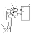
- FIG. 2 is a diagram showing the configuration of a system from a fuel tank to a fuel injection device.
- a primary fuel tank 11 stores a fuel fed from outside. This fuel is supplied to fuel reformers 13a, 13b by fuel pumps 12a, 12b, respectively.
- the fuel reformer 13a Using exhaust heat and a reforming catalyst, the fuel reformer 13a reforms the fuel from the primary fuel tank 11 so as to increase the octane rating of this fuel. Using exhaust heat, the fuel reformer 13b reforms the fuel from the primary fuel tank 11 so as to decrease the octane rating of the fuel.
- the high octane fuel (low auto-ignition fuel) obtained through reforming made by the fuel modifier 13a is stored in a secondary fuel tank 14a.
- the low octane fuel (high auto-ignition fuel) obtained through reforming made by the fuel modifier 13b is stored in a secondary fuel tank 14b.
- the secondary fuel tank 14a has a sensor 15a for detecting the quantity of remaining high octane fuel
- the secondary fuel tank 14b has a sensor 15b for detecting the quantity of remaining low octane fuel.
- the production process for the reformed fuels and their storage in the fuel tanks may be the same as those described in U.S. Patent No. 7,263,967 .
- the fuel injection valve shown in FIG. 1 is composed of two fuel injection valves, 16a and 16b, disposed in an intake passage and a combustion chamber of the engine 20, so as to supply a fuel into the corresponding engine cylinder.
- Fuel injection valves 16a, 16b are disposed as such for each cylinder.
- the high and low octane fuels stored in the secondary fuel tanks 14a and 14b, respectively, are supplied to the fuel injection valves 16a and 16b by corresponding pressure pumps. Controlling the quantity of fuel supplied to each fuel injection value makes it possible to supply the high octane and low octane fuels to the engine 20 from the fuel injection valves 16a and 16b in required proportions.
- the ratio of high to low octane fuel supplied to the fuel injection valves 16a and 16b is controlled by the ECU 101 in accordance with the operating conditions of the engine 20.
- the ECU 101 controls the quantity of fuel supplied.
- the ECU 101 Based upon an output requested by a driver, which is calculated by request output calculating device described below, and which is based upon the degree of opening of the accelerator, the ECU 101 is able to control an engine load (i.e., the quantity of fuel supplied per unit rotation of the engine) as necessary.
- an engine load i.e., the quantity of fuel supplied per unit rotation of the engine
- the engine revolution speed can be controlled, as required, by controlling the gear change ratio of the non-stage transmission.
- FIG. 3 is a flowchart illustrating the process of setting a maximum permissible load according to the first embodiment.
- step S12 using the sensor 15a, the ECU 101 detects a quantity Qa of fuel remaining in the secondary fuel tank 14a (i.e., fuel with an octane rating higher than the fuel stored in fuel tank 14b).
- step S13 the ECU 101 then determines whether the detected quantity Qa of fuel is less than a predetermined value Qi.
- the predetermined value Qi is a threshold for determining whether a fuel used for the engine should be switched or not. If the quantity Qa of remaining fuel is less than the predetermined value Qi in step S13, only the low octane fuel is used or the proportion of low octane fuel to be supplied is increased regardless of the operating conditions of the engine 20.
- FIG. 4 is a flowchart illustrating the process of setting a minimum permissible load according to the first embodiment.
- step S32 using sensor 15b, the ECU 101 detects a quantity Qb of fuel remaining in the secondary fuel tank 14b (i.e., fuel with an octane rating lower than the fuel stored fuel tank 14a).
- step S33 the ECU 101 then determines whether the detected quantity Qb of fuel is less than the predetermined value Qi. If the determination is made in step S33 that the quantity Qb of remaining fuel is less than the predetermined value Qi, only the high octane fuel is used, or the proportion of the high octane fuel to be supplied is increased, regardless of the operating conditions of the engine 20.
- the minimum permissible load Tc is set in step S35.
- FIG. 5 is a flowchart illustrating engine load control and engine revolution speed control according to the present embodiment.
- APO degree of opening of the accelerator
- VSP vehicle speed
- the engine revolution speed can be calculated by an operation or from the output map.
- the AT control unit 201 that has received the gear change instruction sets the gear change ratio so that the engine revolves at the set speed.
- step S62 If the request load is smaller than the minimum permissible load Tc in step S62, the flow proceeds to step S63 where the engine load is set to the minimum permissible load Tc, followed by step S57 where the engine revolution speed is set so as to satisfy the request output and gives a speed change instruction to the non-stage transmission.
- the AT control unit 201 that has received the speed change instruction sets the gear change ratio so that the engine revolves at the set speed.
- FIG. 7 shows changes in the engine load and engine revolution speed where the initial engine load (indicated by the empty circle in the diagram) reaches the request load (indicated by the hatched circle) on account of an increase in the degree of opening of the accelerator.
- the engine load is first increased to the maximum permissible load Tm (indicated by the arrow (1). Subsequently, in order to satisfy the request output, the engine revolution speed is increased and then the engine load and engine revolution speed are manipulated so as to fall on the equal output line including the request output and on the line representing the maximum permissible load Tm (indicated by the arrow (2) and solid circle) of the engine. Equal output lines as in the diagram indicate that the greater the engine load and engine revolution speed, the higher the output.
- step S57 in the control flowchart in may be replaced by a step taking account of the addition of the high octane fuel.
- the engine revolution speed is first calculated in step S571 so as to satisfy the request output.
- step S572 the revolution speed found in step S571 is set by increasing only a predetermined number of revolutions, and the engine load is also set so as to satisfy the request output according to the altered number of engine revolutions.
- command values are output to the engine 20 and the non-stage transmission.
- the engine revolution speed is increased so as not to discomfort the driver or degrade fuel economy.
- This revolution speed is set in advance so as to match vehicle characteristics.
- FIG. 9 shows changes in the engine load and engine revolution speed which result from the additional supply of high octane fuel to the secondary fuel tank.
- the reforming speed of the fuel reformer is increased.
- the fuel reformer reforms the fuels by utilizing exhaust heat. Accordingly, increases in the exhaust flow rate and temperature increase the quantity of heat transferred to the fuel reformer, and hence the reforming speed.
- the engine load is decreased from a point (indicated by the dotted circle in FIG. 9 ) on the equal output line and the line representing the maximum permissible load Tm Simultaneously the engine revolution speed is increased (as indicated by the arrow (3) and solid circle in FIG. 9 ), thereby increasing exhaust flow rate and temperature.
- the engine load and engine revolution speed are manipulated to increase the reforming speed.
- the engine load and engine revolution speed may be altered gradually so that only a predetermined number of engine revolutions is increased when the fuel remaining in the secondary fuel tank 14a has become less than a quantity Qh set slightly larger than the quantity Qi. In this control mechanism, until the quantity of remaining fuel increases from Qh to Qi, the maximum permissible load is not set, and only the number of engine revolutions is increased.
- FIG. 10 is a diagram showing changes in the engine load and engine revolution speed where a quantity of low octane fuel remaining in the secondary fuel tank according to the first embodiment is less than the predetermined value (i.e., the flag for setting the minimum permissible load is ON).
- FIG. 10 illustrates a method of controlling the engine load and engine revolution speed where the initial engine load (indicated by the empty circle in the diagram) reaches the request load (indicated by the hatched circle) on account of a decease in the degree of opening of the accelerator.
- the engine load is decreased to the minimum permissible load Tc (indicated by the arrow (4).
- the engine revolution speed is decreased so as to fall on the equal output line including the request output and on the line representing the minimum permissible load Tc (indicated by the arrow (5) of the engine.
- the ECU 101 decreases the engine revolution speed (indicated by the allow (6) and the solid circle in FIG. 10 ).
- the engine load and engine revolution speed are controlled to prevent any degrading in the fuel economy of the engine.
- a control derive for an internal combustion engine includes a device for detecting the quantity of fuel remaining in a secondary fuel tank (e.g., sensor 15 for the quantity of remaining fuel); a non-stage transmission capable of continuously adjusting an engine revolution speed; an engine load control device for controlling an engine load; and an engine revolution speed control device for controlling the engine revolution speed by use of the non-stage transmission.
- the control device controls the engine load and engine revolution speed based upon a request output and the quantity of fuel determined to be remaining in the secondary fuel tank. This makes it possible to set an engine load and engine revolution speed that match the quantity of fuel remaining in the secondary fuel tank. Thus, any degrading of running performance, resulting from an insufficient quantity of remaining reformed fuel (i.e., secondary fuel), can be prevented.
- the control device controls the engine load and engine revolution speed so as to boost the reforming speed. Accordingly, the engine load and engine revolution speed can be set so as to replenish the reformed fuel speedily. This minimizes incidences of insufficient quantity of the reformed fuel (i.e., secondary fuel), thus ensuring speedy return to pre-set optimum conditions (e.g., engine load and engine revolution speed) for the internal combustion engine 20.
- the fuel reformer 13a reforms a fuel to high octane type and stores it in the secondary fuel tank 14a. If the quantity of high octane fuel remaining in the secondary fuel tank is less than the predetermined value, the control device sets a maximum value for the engine load operable without knocking, even given the absence of high octane fuel from the fuel supplied to the maximum permissible load (i.e., internal combustion engine 20). In addition, when a request output is increased, the control device sets the engine load to the maximum permissible load or below, and adjusts the engine revolution speed so as to satisfy the request output.
- the fuel reformer 13b reforms a fuel to low octane type and stores it in the secondary fuel tank 14b. If the quantity of low octane fuel remaining in the secondary fuel tank is less than the predetermined value, the control device sets a minimum value for the engine load operable without misfires, even given the absence of low octane fuel from the fuel supplied to the minimum permissible load (i.e., internal combustion engine 20). Also, when the request output decreases, the control device sets the engine load to the minimum permissible load or greater, and adjusts the engine revolution speed to satisfy the request output.
- the minimum permissible load i.e., internal combustion engine 20
- a high octane fuel is supplied from a secondary fuel tank 24a to the engine 20 via a fuel injection valve 26a, and a low octane fuel is supplied from a secondary fuel tank 24b to the engine 20 via a fuel injection valve 26b, such that the high and low octane fuels are not mixed together inside the fuel injection valves 26a and 26b.
- the high and low octane fuels are separately supplied to the internal combustion engine 20 by the corresponding fuel injection valves without being mixed. This makes it possible to adjust the octane rating of each fuel according to the quantity of each fuel injected by the corresponding fuel injection valve.
- This modified example includes only one fuel reformer, only one secondary fuel tank, and only one sensor for detecting a quantity of fuel remaining in the secondary fuel tank.
- Only the fuel stored in a secondary fuel tank 34a can be supplied to a fuel injection valve 36a whereas the fuel stored in the primary fuel tank 11 and the fuel stored in the secondary fuel tank 34a can simultaneously be supplied to a fuel injection valve 36b.
- fuel injection valve 36b can inject a mixture of fuel comprising 20% from the primary fuel tank 11 and 80% from the secondary fuel tank 34a.
- any desired mixture could be selected from fuel tanks 11, 34a.
- the fuel reformer 13a reforms a fuel in the primary fuel tank 11 so as to increase the octane rating of the fuel, and the high octane fuel yielded by the reforming is stored in the secondary fuel tank 34a. This obviates the need for the steps (i.e., all the steps in FIG. 3 and steps S61 to S63 in FIG. 4 ) for engine load control using the minimum permissible load as described in the first embodiment.
- the fuel reformer 13a may reform a fuel so as to decrease its octane rating, and the low octane fuel yielded by the reforming may be stored in the secondary fuel tank 34a. This obviates the need for steps (i.e., all the steps in FIG. 2 and steps S54 to S56 in FIG. 4 ) for the engine load control that uses the maximum permissible load as described in the first embodiment.
- the number of fuel reformers, secondary fuel tanks, and sensors for measuring the quantity of fuel remaining in the secondary fuel tank may equal one. Compared to the first embodiment, this reduces the installation space and simplifies the configuration of the control device for the engine.
Abstract
Description
- The present invention relates generally to a control device for an internal combustion engine and particularly, but not exclusively, to a control device for an internal combustion engine that has a fuel reformer. Aspects of the invention relate to an apparatus, to a device, to a system, to a method and to a vehicle.
- A low octane fuel is highly ignitable and, therefore, appropriate for running an engine under conditions for lean burning or for igniting a compressed homogenous fuel mixture, both of which are effective in improving fuel economy. However, the low octane fuel is more likely to cause knocking during high load running and, accordingly, is not appropriate for high load running. In contrast to the low octane fuel, a high octane fuel is less likely to cause knocking and, therefore, appropriate for high load running. However, the high octane fuel is not highly ignitable and is not appropriate either for running the engine under conditions for lean burning or the like.
- A vehicle that can use fuels of different octane ratings depending on an operating range may have both improved engine output and greater fuel economy. In view of these advantages, a technology has been proposed in which a fuel externally supplied to a vehicle is reformed to a fuel that has a different octane rating, and the fuel with a desired octane rating that matches running conditions of the engine is supplied to the engine.
- However, such a conventional technology does not take account of the quantity of remaining reformed fuel. For example, if there is insufficient low octane fuel, a high octane fuel must be added to offset the insufficiency. This increases the octane rating and degrades ignitability in low load burning conditions, with the result that the engine is more likely to produce unstable burning. On the other hand, if there is insufficient high octane fuel, a low octane fuel must be added to offset the insufficiency. This decreases the octane rating and makes the engine more likely to fail during high load burning conditions due to knocking.
- It is an aim of the invention to address this issue and to improve upon known technology. Embodiments of the invention may provide a control device for an internal combustion engine which prevents the degradation of engine running performance even if the octane rating of a fuel supplied to the engine varies widely. Other aims and advantages of the invention will become apparent from the following description, claims and drawings.
- Aspects of the invention therefore comprise an apparatus, a system, a method and a vehicle as claimed in the appended claims.
- According to another aspect of the invention for which protection is sought there is provided an internal combustion engine system, comprising a primary fuel tank that stores a fuel, a fuel reformer that reforms the fuel from the primary fuel tank, a secondary fuel tank that stores the fuel reformed by the fuel reformer, a fuel injection device that injects the fuel that is selectably supplied from either the primary fuel tank or secondary fuel tank into a combustion chamber, a sensor that detects the quantity of fuel remaining in the secondary fuel tank and a control device that sets and outputs a load and revolution speed of the engine, wherein the control device is configured to set the engine load and engine revolution speed according to a request output determ ined based upon an operation performed by an operator and the engine load and engine revolution speed when the quantity of fuel remaining in the secondary fuel tank is more than a predetermined value, are set different than when the quantity of fuel remaining in the secondary fuel tank is less than the predetermined value.
- In an embodiment, when the quantity of fuel remaining in the secondary fuel tank is less than the predetermined value, the engine revolution speed is set higher to boost the reforming speed of the fuel reformer, as compared to when the quantity of fuel remaining in the secondary fuel tank is more than the predetermined value.
- In an embodiment, the fuel reformer reforms the fuel to a high octane type as compared to the fuel stored in the primary fuel tank, if the sensor detects that the quantity of high octane fuel remaining in the secondary tank is less than the predetermined value, the control device sets a maximum permissible engine load, and if the engine load set by the control device exceeds the maximum permissible load, the engine load is adjusted to the maximum permissible load or below.
- In an embodiment, the maximum permissible load is a maximum value for the engine load operable without knocking, even in the absence of the high octane fuel from the fuel supplied to the engine.
- In an embodiment, the fuel reformer reforms the fuel to a low octane type as compared to the fuel stored in the primary fuel tank, if the sensor detects that the quantity of low octane fuel remaining in the secondary tank is less than the predetermined value, the control device sets a minimum permissible engine load, and if the engine load set by the control device is below the minimum permissible load, the engine load is adjusted to the minimum permissible load or more.
- In an embodiment, the minimum permissible load is a minimum value for the engine load operable without misfires, even in the absence of the low octane fuel from the fuel supplied to the engine.
- In an embodiment, the request output is calculated based on a degree of opening of an accelerator.
- According to yet another aspect of the invention for which protection is sought there is provided an internal combustion engine system, comprising a primary fuel tank that stores a fuel, fuel reforming means for reforming the fuel from the primary fuel tank, a secondary fuel tank that stores the fuel reformed by the fuel reforming means, fuel injection means for injecting the fuel selected from the primary fuel tank or secondary fuel tank into a combustion chamber, sensing means for detecting the quantity of fuel remaining in the secondary fuel tank and control means for setting and outputting a load and revolution speed of the engine, wherein control means is configured to set the engine load and engine revolution speed according to a request output determined based upon an operation performed by an operator, and the engine load and engine revolution speed when the quantity of fuel remaining in the secondary fuel tank is more than a predetermined value, are set different than when the quantity of fuel remaining in the secondary fuel tank is less than the predetermined value.
- In an embodiment, the fuel injection device injects a mixture of fuel that is selectably supplied from the primary fuel tank and secondary fuel tank into the combustion chamber.
- According to a further aspect of the invention for which protection is sought there is provided a method of setting an internal combustion engine load and revolution speed, comprising storing a fuel in a primary fuel tank, reforming the fuel from the primary fuel tank, storing the reformed fuel in a secondary fuel tank, injecting the fuel selected from the primary fuel tank or secondary fuel tank into a combustion chamber, detecting the quantity of fuel remaining in the secondary fuel tank and setting and outputting the engine load and revolution speed according to a request output determined based upon an operation performed by an operator, wherein the engine load and revolution speed are set different when the quantity of fuel remaining in the secondary fuel tank is more than a predetermined value, as compared to when the quantity of fuel remaining in the secondary fuel tank is less than the predetermined value.
- In an embodiment, an internal combustion engine system comprises a primary fuel tank that stores a fuel, a fuel reformer that reforms the fuel from the primary fuel tank, a secondary fuel tank that stores the fuel reformed by the fuel reformer, a fuel injection device that injects the fuel selectably supplied from either the primary fuel tank or secondary fuel tank into a combustion chamber, a sensor that detects the quantity of fuel remaining in the secondary fuel tank, and a control device that sets and outputs a load and revolution speed of the engine. The control device is configured to set the engine load and engine revolution speed according to a request output determined based upon an operation performed by an operator. The engine load and engine revolution speed when the quantity of fuel remaining in the secondary fuel tank is more than a predetermined value, are set different than when the quantity of fuel remaining in the secondary fuel tank is less than the predetermined value.
- In another embodiment, a method of setting an internal combustion engine load and revolution speed comprises storing a fuel in a primary fuel tank, reforming the fuel from the primary fuel tank, storing the reformed fuel in a secondary fuel tank, injecting the fuel selected from the primary fuel tank or secondary fuel tank into a combustion chamber, detecting the quantity of fuel remaining in the secondary fuel tank, and setting and outputting the engine load and revolution speed according to a request output determined based upon an operation performed by an operator. The engine load and revolution speed are set different when the quantity of fuel remaining in the secondary fuel tank is more than a predetermined value, as compared to when the quantity of fuel remaining in the secondary fuel tank is less than the predetermined value.
- The present invention makes it possible to set an engine load and engine revolution speed according to the quantity of remaining fuel (secondary fuel) reformed by a fuel reformer. In response to an insufficient quantity of remaining secondary fuel, the fuel to be used is switched. Even if the octane rating of the fuel supplied to the engine varies, the fuel reformer produces a suitable secondary fuel to replenish a secondary fuel tank. In addition, while satisfying a request output, the engine can run stably without knocking, misfires, etc.
- Within the scope of this application it is envisaged that the various aspects, embodiments, examples, features and alternatives set out in the preceding paragraphs, in the claims and/or in the following description and drawings may be taken individually or in any combination thereof.
- The present invention will now be described, by way of example only, with reference to the accompanying drawings in which:
-
FIG. 1 is a diagram showing a power transmission device according to a first embodiment of the invention; -
FIG. 2 is a diagram showing a system from a fuel tank to a fuel injection device according the first embodiment; -
FIG. 3 is a flowchart illustrating the process of setting a maximum permissible load according to the first embodiment; -
FIG. 4 is a flowchart illustrating the process of setting a minimum permissible load according to the first embodiment; -
FIG. 5 is a flowchart illustrating engine load control and engine revolution speed control according to the first embodiment; -
FIG. 6 is a map used for calculating a target drive force from a vehicle speed and the degree of opening of an accelerator (APO); -
FIG. 7 is a diagram illustrating a method of controlling an engine load and engine revolution speed when a quantity of high octane fuel remaining in a secondary fuel tank is less than a predetermined value in accordance with the first embodiment; -
FIG. 8 is a flowchart illustrating an additional control according to the first em bodiment; -
FIG. 9 is a diagram illustrating a method of controlling an engine load and engine revolution speed when a quantity of high octane fuel remaining in the secondary fuel tank is less than a predetermined value in accordance with the first embodiment; -
FIG. 10 is a diagram illustrating a method of controlling an engine load and engine revolution speed when a quantity of low octane fuel remaining in a secondary fuel tank is less than a predetermined value in accordance with the first embodiment; -
FIG. 11 is a diagram showing the configuration of a control device for an internal combustion engine according to a second embodiment; and -
FIG. 12 is a diagram showing the configuration of a control device for an internal combustion engine according to a third embodiment. -
FIG. 1 shows apower transmission device 1, from an engine to drive wheels, according to a first embodiment of the invention. - The
power transmission device 1 includes an internal combustion engine (hereafter "engine") 20 for use as a drive source, the crankshaft of which is connected to a belt drivetype non-stage transmission 31 via atorque converter 21. - The
torque converter 21 is provided for use as a starting element, and includes apump impeller 211, aturbine runner 212, astator 213, and alockup clutch 214. Thelockup clutch 214 is connected to theturbine runner 212, and mechanically directly connects the crankshaft of theengine 20 and the input shaft of thenon-stage transmission 31 by pressing a clutch facing 214a against the internal face of aclutch housing 215, which is formed integrally with thepump impeller 211. - The
non-stage transmission 31 includes aninput pulley 311 and anoutput pulley 312, as well as a V-shaped metal belt 313 wound around thepulleys transmission 31 can be changed by making an input pulley ratio different from an output pulley ratio (i.e., making a ratio of the effective diameter of theinput pulley 311 different from the effective diameter of output pulley 312). Thenon-stage transmission 31 further includes afinal gear 314, which reduces a drive force, as a final stage after the gear change made by thepulleys non-stage transmission 31 has aforward clutch 315 for use as a multiple disc clutch, which switches the range to neutral or drive and disconnects the output shaft of thetorque converter 21 and the input shaft (i.e., the rotating shaft of the input pulley 311) of the non-stagetransmission 31. With theforward clutch 315 released, the transmission of the drive force of theengine 20 to thenon-stage transmission 31 is stopped, thereby setting thetransmission 31 to the neutral range. - In the
power transmission device 1 having the foregoing configuration, the drive force generated by theengine 20 is transmitted to thenon-stage transmission 31 via thetorque converter 21, then converted into a predetermined gear change ratio ip by thetransmission 31, and transmitted to left andright drive wheels 61 via a differential gear 41 anddrive shafts 51. - Based on command signals from an
AT control unit 201, hydraulic control valves provided for corresponding devices operate the non-stage transmission 31 (such as changing the pulley ratio) and engage or disengage thelockup clutch 214. - The
AT control unit 201 inputs signals supplied from, for example: avehicle sensor 205 that detects a vehicle speed (VSP); aninhibiter switch 206; anoil temperature sensor 207 that detects the temperature of a transmission hydraulic fluid (TF); and arevolution number sensor 208 that detects the number of revolutions of the turbine runner 212 (hereinafter referred to as "the number of turbine revolutions") (NT) for use as the input number of revolutions for the non-stagetransmission 31. TheAT control unit 201 also inputs the degree of opening of the accelerator (APO) and the number of revolutions of the engine (NE), which are supplied from anengine control unit 101. Based upon the input degree of opening of the accelerator (APO) and input vehicle speed (VSP), theAT control unit 201 performs predetermined operations related to transmission control, etc., and outputs command signals to the hydraulic control valves provided for theinput pulley 311 andoutput pulley 312, as well as the hydraulic control valve provided for thelockup clutch 214 of thetorque converter 21. In the first embodiment, by driving the movable members of the input andoutput pulleys AT control unit 201 exerts transmission control so that the non-stagetransmission 31 has a predetermined gear change ratio ip matching the running conditions of the vehicle. - The engine control unit (ECU) 101 controls the
engine 20, and perform s predetermined operations for engine control, etc. through input signals supplied from, for example, anaccelerator sensor 105 that detects the degree of operation of the accelerator pedal (i.e., the degree of opening of the accelerator (APO); acrank angle sensor 106 detecting a unit crank angle or reference crank angle (based upon which the num ber of revolutions of the engine (NE) can be calculated); and awater temperature sensor 107 that detects the temperature of engine cooling water (TW). In addition, there is provided anidle switch 108 that outputs an ON-signal when the opening of the accelerator is fully closed for a speed reduction fuel cut. Theidle switch 108 outputs an ON-signal when the accelerator pedal has been completely returned to its original position. This idle switch is disposed together with a throttle sensor (not shown). A signal from theidle switch 108 is output to theengine control unit 101. Normally theengine control unit 101 supplies afuel injection valve 16 with a fuel injection control signal set based upon the degree of opening of the accelerator (APO), the number of revolutions of the engine (NE), etc. -
FIG. 2 is a diagram showing the configuration of a system from a fuel tank to a fuel injection device. - A
primary fuel tank 11 stores a fuel fed from outside. This fuel is supplied to fuelreformers fuel pumps - Using exhaust heat and a reforming catalyst, the
fuel reformer 13a reforms the fuel from theprimary fuel tank 11 so as to increase the octane rating of this fuel. Using exhaust heat, thefuel reformer 13b reforms the fuel from theprimary fuel tank 11 so as to decrease the octane rating of the fuel. - The high octane fuel (low auto-ignition fuel) obtained through reforming made by the
fuel modifier 13a is stored in asecondary fuel tank 14a. The low octane fuel (high auto-ignition fuel) obtained through reforming made by thefuel modifier 13b is stored in asecondary fuel tank 14b. Thesecondary fuel tank 14a has asensor 15a for detecting the quantity of remaining high octane fuel, and thesecondary fuel tank 14b has asensor 15b for detecting the quantity of remaining low octane fuel. The production process for the reformed fuels and their storage in the fuel tanks may be the same as those described inU.S. Patent No. 7,263,967 . - The fuel injection valve shown in
FIG. 1 is composed of two fuel injection valves, 16a and 16b, disposed in an intake passage and a combustion chamber of theengine 20, so as to supply a fuel into the corresponding engine cylinder.Fuel injection valves secondary fuel tanks fuel injection valves engine 20 from thefuel injection valves - The ratio of high to low octane fuel supplied to the
fuel injection valves ECU 101 in accordance with the operating conditions of theengine 20. - In addition to controlling the fuel supply proportion by use of fuel supply proportion control, the
ECU 101 controls the quantity of fuel supplied. - Based upon an output requested by a driver, which is calculated by request output calculating device described below, and which is based upon the degree of opening of the accelerator, the
ECU 101 is able to control an engine load (i.e., the quantity of fuel supplied per unit rotation of the engine) as necessary. - Since the output shaft of the
engine 20 is connected to the non-stage transmission, the engine revolution speed can be controlled, as required, by controlling the gear change ratio of the non-stage transmission. -
FIG. 3 is a flowchart illustrating the process of setting a maximum permissible load according to the first embodiment. - In step S12, using the
sensor 15a, theECU 101 detects a quantity Qa of fuel remaining in thesecondary fuel tank 14a (i.e., fuel with an octane rating higher than the fuel stored infuel tank 14b). In step S13, theECU 101 then determines whether the detected quantity Qa of fuel is less than a predetermined value Qi. The predetermined value Qi is a threshold for determining whether a fuel used for the engine should be switched or not. If the quantity Qa of remaining fuel is less than the predetermined value Qi in step S13, only the low octane fuel is used or the proportion of low octane fuel to be supplied is increased regardless of the operating conditions of theengine 20. In step S14, on the other hand, a flag for setting the maximum permissible load is switched ON (Ta = 1). Then, the maximum permissible load Tm is set instep 15. The maximum permissible load Tm, which is stored in theECU 101 in advance, is a maximum value of load that does not affect theengine 20 performing knock-free operation, even in the absence of the high octane fuel. If the determination is made in step S13 that the quantity Qa of remaining fuel is equal to or more than the predetermined value Qi, the flag for setting the maximum permissible load is switched OFF (Ta = 0) in step S24 and, therefore, the maximum permissible load Tm is not set. -
FIG. 4 is a flowchart illustrating the process of setting a minimum permissible load according to the first embodiment. - In step S32, using
sensor 15b, theECU 101 detects a quantity Qb of fuel remaining in thesecondary fuel tank 14b (i.e., fuel with an octane rating lower than the fuel storedfuel tank 14a). In step S33, theECU 101 then determines whether the detected quantity Qb of fuel is less than the predetermined value Qi. If the determination is made in step S33 that the quantity Qb of remaining fuel is less than the predetermined value Qi, only the high octane fuel is used, or the proportion of the high octane fuel to be supplied is increased, regardless of the operating conditions of theengine 20. In step S34, on the other hand, a flag for setting the minimum permissible load is switched ON (Tb = 1). Then, the minimum permissible load Tc is set in step S35. The minimum permissible load Tc, which is stored in theECU 101 in advance, is a minimum value of load that does not affect theengine 20 performing without misfires, even in the absence of the low octane fuel. If the determination is made in step S33 that the quantity Qb of remaining fuel is equal to or larger than the predetermined value Qi, the flag for setting the minimum permissible load is switched OFF (Tb = 0) in step S44 and, therefore, the minimum permissible load Tc is not set. -
FIG. 5 is a flowchart illustrating engine load control and engine revolution speed control according to the present embodiment. - In step S52, using a sensor, the
ECU 101 detects the degree of opening of the accelerator. Based upon this degree, the request output calculating device of theECU 101 calculates a request output (and request load) in step S53. Using a map shown inFIG. 6 , the request output calculating device calculates a target drive force for the vehicle from the degree of opening of the accelerator (APO) and the vehicle speed (VSP), and also calculates the request output and request load for the engine, taking account of fuel efficiency, etc. Subsequently, in step S54, theECU 101 determines whether the flag for setting the maximum permissible load is ON (Ta = 1) or not. If the flag for setting the maximum permissible load is ON (Ta = 1) in step S54, the flow proceeds to step S55 where a determination is made whether the request load is greater than the maximum permissible load Tm or not. If the request load is greater than the maximum permissible load Tm in step S55, the flow proceeds to step S56 where the engine load is set to the maximum permissible load Tm , followed by step S57 where the engine revolution speed is set so as to satisfy the request output, and a gear change instruction is given to the non-stage transmission. The engine revolution speed can be calculated by an operation or from the output map. TheAT control unit 201 that has received the gear change instruction sets the gear change ratio so that the engine revolves at the set speed. - If the flag for setting the maximum permissible load is not ON (Ta = 1) (i.e., the flag for setting the maximum permissible load is OFF (Ta = 0) in step S54, or if the request load is equal to or lower than the maximum permissible load Tm in step S55, the flow proceeds to step S61 where a determination is made whether the flag for setting the minimum permissible load is ON (Tb = 1) or not. If the flag is On (Tb = 1) in step S61, the flow proceeds to step S62 where a determination is made whether the request load is smaller than the minimum permissible load Tc. If the request load is smaller than the minimum permissible load Tc in step S62, the flow proceeds to step S63 where the engine load is set to the minimum permissible load Tc, followed by step S57 where the engine revolution speed is set so as to satisfy the request output and gives a speed change instruction to the non-stage transmission. The
AT control unit 201 that has received the speed change instruction sets the gear change ratio so that the engine revolves at the set speed. - If the flag for setting the minimum permissible load is not ON (Tb = 1) in step S61 (i.e., if the flag for setting the minimum permissible load is OFF (Tb = 0), or the request load is equal to or greater than the minimum permissible load Tc in step S62, the flow proceeds to step S71 where the engine load is set to the request load, the engine revolution speed is set so as to satisfy the request output, and the engine revolution speed is controlled using the non-stage transmission.
- Next will be described the load and engine revolution speed, where a quantity of high octane fuel in the secondary fuel tank of the first embodiment is less than the predetermined value (i.e., where the flag for setting the maximum permissible load is ON).
-
FIG. 7 shows changes in the engine load and engine revolution speed where the initial engine load (indicated by the empty circle in the diagram) reaches the request load (indicated by the hatched circle) on account of an increase in the degree of opening of the accelerator. - If the request load (indicated by the hatched circle) is greater than the maximum permissible load Tm, the engine load is first increased to the maximum permissible load Tm (indicated by the arrow (1). Subsequently, in order to satisfy the request output, the engine revolution speed is increased and then the engine load and engine revolution speed are manipulated so as to fall on the equal output line including the request output and on the line representing the maximum permissible load Tm (indicated by the arrow (2) and solid circle) of the engine. Equal output lines as in the diagram indicate that the greater the engine load and engine revolution speed, the higher the output.
- This makes it possible to prevent knocking even where the quantity Qb of high octane fuel remaining in the
second fuel tank 14a becomes less than the predetermined value Qi, and the supply of high octane fuel is, therefore, limited or stopped, with the result that the engine is run using only the low octane fuel in thesecondary fuel tank 14b. - As shown in
Fig. 8 , in the first embodiment, step S57 in the control flowchart in may be replaced by a step taking account of the addition of the high octane fuel. In this case, the engine revolution speed is first calculated in step S571 so as to satisfy the request output. Subsequently, in step S572, the revolution speed found in step S571 is set by increasing only a predetermined number of revolutions, and the engine load is also set so as to satisfy the request output according to the altered number of engine revolutions. Then, command values are output to theengine 20 and the non-stage transmission. The engine revolution speed is increased so as not to discomfort the driver or degrade fuel economy. This revolution speed is set in advance so as to match vehicle characteristics.FIG. 9 shows changes in the engine load and engine revolution speed which result from the additional supply of high octane fuel to the secondary fuel tank. - In order that the quantity of high octane fuel remaining in the secondary fuel tank be equal to or higher than the predetermined value at an early stage, the reforming speed of the fuel reformer is increased. In the first embodiment, the fuel reformer reforms the fuels by utilizing exhaust heat. Accordingly, increases in the exhaust flow rate and temperature increase the quantity of heat transferred to the fuel reformer, and hence the reforming speed. Specifically, along the equal output line including the request output, the engine load is decreased from a point (indicated by the dotted circle in
FIG. 9 ) on the equal output line and the line representing the maximum permissible load Tm Simultaneously the engine revolution speed is increased (as indicated by the arrow (3) and solid circle inFIG. 9 ), thereby increasing exhaust flow rate and temperature. Thus, the engine load and engine revolution speed are manipulated to increase the reforming speed. Alternatively, the engine load and engine revolution speed may be altered gradually so that only a predetermined number of engine revolutions is increased when the fuel remaining in thesecondary fuel tank 14a has become less than a quantity Qh set slightly larger than the quantity Qi. In this control mechanism, until the quantity of remaining fuel increases from Qh to Qi, the maximum permissible load is not set, and only the number of engine revolutions is increased. -
FIG. 10 is a diagram showing changes in the engine load and engine revolution speed where a quantity of low octane fuel remaining in the secondary fuel tank according to the first embodiment is less than the predetermined value (i.e., the flag for setting the minimum permissible load is ON). -
FIG. 10 illustrates a method of controlling the engine load and engine revolution speed where the initial engine load (indicated by the empty circle in the diagram) reaches the request load (indicated by the hatched circle) on account of a decease in the degree of opening of the accelerator. - Since the request load (indicated by the hatched circle in
FIG. 10 ) is smaller than the minimum permissible load Tc, the engine load is decreased to the minimum permissible load Tc (indicated by the arrow (4). Subsequently, in order to satisfy the request output, the engine revolution speed is decreased so as to fall on the equal output line including the request output and on the line representing the minimum permissible load Tc (indicated by the arrow (5) of the engine. Thereafter, as well as increasing the engine load along the equal output line, theECU 101 decreases the engine revolution speed (indicated by the allow (6) and the solid circle inFIG. 10 ). Thus, the engine load and engine revolution speed are controlled to prevent any degrading in the fuel economy of the engine. - In the first embodiment described above, a control derive for an internal combustion engine includes a device for detecting the quantity of fuel remaining in a secondary fuel tank (e.g.,
sensor 15 for the quantity of remaining fuel); a non-stage transmission capable of continuously adjusting an engine revolution speed; an engine load control device for controlling an engine load; and an engine revolution speed control device for controlling the engine revolution speed by use of the non-stage transmission. The control device controls the engine load and engine revolution speed based upon a request output and the quantity of fuel determined to be remaining in the secondary fuel tank. This makes it possible to set an engine load and engine revolution speed that match the quantity of fuel remaining in the secondary fuel tank. Thus, any degrading of running performance, resulting from an insufficient quantity of remaining reformed fuel (i.e., secondary fuel), can be prevented. - According to the first embodiment, if the quantity of fuel remaining in the secondary fuel tank detected by the
sensor 15, is less than a predetermined value, the control device controls the engine load and engine revolution speed so as to boost the reforming speed. Accordingly, the engine load and engine revolution speed can be set so as to replenish the reformed fuel speedily. This minimizes incidences of insufficient quantity of the reformed fuel (i.e., secondary fuel), thus ensuring speedy return to pre-set optimum conditions (e.g., engine load and engine revolution speed) for theinternal combustion engine 20. - Additionally, in the first embodiment, the
fuel reformer 13a reforms a fuel to high octane type and stores it in thesecondary fuel tank 14a. If the quantity of high octane fuel remaining in the secondary fuel tank is less than the predetermined value, the control device sets a maximum value for the engine load operable without knocking, even given the absence of high octane fuel from the fuel supplied to the maximum permissible load (i.e., internal combustion engine 20). In addition, when a request output is increased, the control device sets the engine load to the maximum permissible load or below, and adjusts the engine revolution speed so as to satisfy the request output. This prevents such a situation as that when the fuel supplied to theinternal combustion engine 20 is switched from high octane fuel to another fuel due to an insufficient quantity of high octane fuel, the engine load is possibly increased too high, resulting in knocking during the time taken for the remaining high octane fuel to recover to the predetermined level. - In the first embodiment, the
fuel reformer 13b reforms a fuel to low octane type and stores it in thesecondary fuel tank 14b. If the quantity of low octane fuel remaining in the secondary fuel tank is less than the predetermined value, the control device sets a minimum value for the engine load operable without misfires, even given the absence of low octane fuel from the fuel supplied to the minimum permissible load (i.e., internal combustion engine 20). Also, when the request output decreases, the control device sets the engine load to the minimum permissible load or greater, and adjusts the engine revolution speed to satisfy the request output. This prevents such a situation as that when a fuel supplied to theinternal combustion engine 20 is switched from low octane fuel to another fuel due to an insufficient quantity of low octane fuel, the engine load is possibly decreased too low, resulting in misfires for the time taken for the rem aining low octane fuel to recover to the predetermined level. - Next, a modified example of the system will be described with reference to
FIG. 11 . - A description will be given of only the features different from those in the first embodiment shown in
FIG. 2 . - A high octane fuel is supplied from a
secondary fuel tank 24a to theengine 20 via afuel injection valve 26a, and a low octane fuel is supplied from asecondary fuel tank 24b to theengine 20 via afuel injection valve 26b, such that the high and low octane fuels are not mixed together inside thefuel injection valves - According to the modified example, the high and low octane fuels are separately supplied to the
internal combustion engine 20 by the corresponding fuel injection valves without being mixed. This makes it possible to adjust the octane rating of each fuel according to the quantity of each fuel injected by the corresponding fuel injection valve. - Referring to
FIG. 12 , another modified example of the system will be described below. - A description will be given of only the features different from those in the first embodiment shown in
FIG. 2 . - This modified example includes only one fuel reformer, only one secondary fuel tank, and only one sensor for detecting a quantity of fuel remaining in the secondary fuel tank. Only the fuel stored in a
secondary fuel tank 34a can be supplied to afuel injection valve 36a whereas the fuel stored in theprimary fuel tank 11 and the fuel stored in thesecondary fuel tank 34a can simultaneously be supplied to afuel injection valve 36b. For example,fuel injection valve 36b can inject a mixture of fuel comprising 20% from theprimary fuel tank 11 and 80% from thesecondary fuel tank 34a. Of course, any desired mixture could be selected fromfuel tanks - In this embodiment, the
fuel reformer 13a reforms a fuel in theprimary fuel tank 11 so as to increase the octane rating of the fuel, and the high octane fuel yielded by the reforming is stored in thesecondary fuel tank 34a. This obviates the need for the steps (i.e., all the steps inFIG. 3 and steps S61 to S63 inFIG. 4 ) for engine load control using the minimum permissible load as described in the first embodiment. - In this embodiment, the
fuel reformer 13a may reform a fuel so as to decrease its octane rating, and the low octane fuel yielded by the reforming may be stored in thesecondary fuel tank 34a. This obviates the need for steps (i.e., all the steps inFIG. 2 and steps S54 to S56 inFIG. 4 ) for the engine load control that uses the maximum permissible load as described in the first embodiment. - According to this embodiment, the number of fuel reformers, secondary fuel tanks, and sensors for measuring the quantity of fuel remaining in the secondary fuel tank may equal one. Compared to the first embodiment, this reduces the installation space and simplifies the configuration of the control device for the engine.
- While the invention has been disclosed with reference to certain embodiments, numerous modifications, alterations, and changes to the described embodiments are possible without departing from the sphere and scope of the invention, as defined in the appended claims and equivalents thereof. Accordingly, it is intended that the invention not be limited to the described embodiments, but that it have the full scope defined by the language of the following claims.
- This application claims priority from Japanese Patent Application No.
2007-060586, filed 9th March 2007
Claims (11)
- An apparatus for controlling an internal combustion engine having a primary fuel tank for storing a fuel, a fuel reformer for reforming the fuel from the primary fuel tank and a secondary fuel tank for storing the reformed fuel, the apparatus comprising:control means for setting and outputting an engine load and an engine revolution speed of the engine;wherein the control means is arranged to set the engine load and engine revolution speed when the quantity of fuel remaining in the secondary fuel tank is more than a predetermined value different to the engine load and engine revolution speed when the quantity of fuel remaining in the secondary fuel tank is less than the predetermined value.
- An apparatus as claimed in claim 1, wherein the control means is arranged to set the engine revolution speed higher when the quantity of fuel remaining in the secondary fuel tank is less than the predetermined value compared to when the quantity of fuel remaining in the secondary fuel tank is more than the predetermined value, thereby to boost the reforming speed of the fuel reformer.
- An apparatus as claimed in claim 1 or claim 2, wherein the control means is arranged to set a maximum permissible engine load when a quantity of high octane fuel remaining in the secondary tank is less than the predetermined value and, if the engine load set exceeds the maximum permissible load, to adjust the engine load to the maximum permissible load or less.
- An apparatus as claimed in claim 3, wherein the maximum permissible load is a maximum value for the engine load operable without knocking, even in the absence of the high octane fuel from the fuel supplied to the engine.
- An apparatus as claimed in any preceding claim, wherein the control means is arranged to set a minimum permissible engine load when a quantity of low octane fuel remaining in the secondary tank is less than the predetermined value and, if the engine load is below the minimum permissible load, to adjust the engine load to the minimum permissible load or more.
- An apparatus as claimed in claim 5, wherein the minimum permissible load is a minimum value for the engine load operable without misfires, even in the absence of the low octane fuel from the fuel supplied to the engine.
- An apparatus as claimed in any preceding claim, wherein the request output is calculated based on a degree of opening of an accelerator.
- A system for an internal combustion engine, comprising:a primary fuel tank that stores a fuel;fuel reforming means for reforming the fuel from the primary fuel tank;a secondary fuel tank that stores the fuel reformed by the fuel reforming means;fuel injection means for injecting the fuel selected from the primary fuel tank or secondary fuel tank into a combustion chamber;sensing means for detecting the quantity of fuel remaining in the secondary fuel tank; andan apparatus as claimed in any preceding claim.
- A system as claimed in claim 8, wherein the fuel injection means is arranged to inject a mixture of fuel that is selectably supplied from the primary fuel tank and secondary fuel tank into the combustion chamber.
- A vehicle having an apparatus or a system as claimed in any preceding claim.
- A method of setting an internal combustion engine load and revolution speed, comprising:storing a fuel in a primary fuel tank;reforming the fuel from the primary fuel tank;storing the reformed fuel in a secondary fuel tank;injecting the fuel selected from the primary fuel tank or secondary fuel tank into a combustion chamber;detecting the quantity of fuel remaining in the secondary fuel tank; andsetting and outputting the engine load and revolution speed according to a request output determined based upon an operation performed by an operator;wherein the engine load and revolution speed are set different when the quantity of fuel remaining in the secondary fuel tank is more than a predetermined value, as compared to when the quantity of fuel remaining in the secondary fuel tank is less than the predetermined value.
Applications Claiming Priority (1)
| Application Number | Priority Date | Filing Date | Title |
|---|---|---|---|
| JP2007060586A JP4470951B2 (en) | 2007-03-09 | 2007-03-09 | Combustion control device for internal combustion engine |
Publications (2)
| Publication Number | Publication Date |
|---|---|
| EP1980735A1 true EP1980735A1 (en) | 2008-10-15 |
| EP1980735B1 EP1980735B1 (en) | 2011-01-19 |
Family
ID=39682668
Family Applications (1)
| Application Number | Title | Priority Date | Filing Date |
|---|---|---|---|
| EP08152442A Expired - Fee Related EP1980735B1 (en) | 2007-03-09 | 2008-03-07 | Control device for internal combustion engine |
Country Status (5)
| Country | Link |
|---|---|
| US (1) | US7610896B2 (en) |
| EP (1) | EP1980735B1 (en) |
| JP (1) | JP4470951B2 (en) |
| CN (1) | CN101260836B (en) |
| DE (1) | DE602008004584D1 (en) |
Families Citing this family (24)
| Publication number | Priority date | Publication date | Assignee | Title |
|---|---|---|---|---|
| US8099949B2 (en) * | 2008-05-15 | 2012-01-24 | Ford Global Technologies, Llc | Engine exhaust temperature regulation |
| US7845334B2 (en) * | 2008-07-31 | 2010-12-07 | Ford Global Technologies, Llc | Fuel system for multi-fuel engine |
| JP5223969B2 (en) * | 2010-03-09 | 2013-06-26 | トヨタ自動車株式会社 | Control device for internal combustion engine |
| US8245671B2 (en) | 2010-04-08 | 2012-08-21 | Ford Global Technologies, Llc | Operating an engine with reformate |
| US8402928B2 (en) * | 2010-04-08 | 2013-03-26 | Ford Global Technologies, Llc | Method for operating an engine with variable charge density |
| US8037850B2 (en) | 2010-04-08 | 2011-10-18 | Ford Global Technologies, Llc | Method for operating an engine |
| US8191514B2 (en) * | 2010-04-08 | 2012-06-05 | Ford Global Technologies, Llc | Ignition control for reformate engine |
| US8118006B2 (en) | 2010-04-08 | 2012-02-21 | Ford Global Technologies, Llc | Fuel injector diagnostic for dual fuel engine |
| US8146541B2 (en) | 2010-04-08 | 2012-04-03 | Ford Global Technologies, Llc | Method for improving transient engine operation |
| US8001934B2 (en) | 2010-04-08 | 2011-08-23 | Ford Global Technologies, Llc | Pump control for reformate fuel storage tank |
| US8307790B2 (en) * | 2010-04-08 | 2012-11-13 | Ford Global Technologies, Llc | Method for operating a vehicle with a fuel reformer |
| US8015952B2 (en) * | 2010-04-08 | 2011-09-13 | Ford Global Technologies, Llc | Engine fuel reformer monitoring |
| US8041500B2 (en) * | 2010-04-08 | 2011-10-18 | Ford Global Technologies, Llc | Reformate control via accelerometer |
| US8230826B2 (en) * | 2010-04-08 | 2012-07-31 | Ford Global Technologies, Llc | Selectively storing reformate |
| US8539914B2 (en) * | 2010-04-08 | 2013-09-24 | Ford Global Technologies, Llc | Method for operating an engine with a fuel reformer |
| US8613263B2 (en) * | 2010-04-08 | 2013-12-24 | Ford Global Technologies, Llc | Method for operating a charge diluted engine |
| US8991368B2 (en) | 2012-02-23 | 2015-03-31 | Discovery Fuel Technologies, Llc | Oxygenate compound synthesis device, systems including the device, and methods of using the same |
| JP5214044B1 (en) * | 2012-03-09 | 2013-06-19 | 三菱電機株式会社 | Fuel control apparatus and method for internal combustion engine |
| WO2013149112A1 (en) * | 2012-03-30 | 2013-10-03 | Monsanto Technology Llc | Alcohol reforming system for internal combustion engine |
| US9010305B2 (en) * | 2013-08-22 | 2015-04-21 | Ford Global Technologies, Llc | Octane separation system and operating method |
| JP6169512B2 (en) * | 2014-03-11 | 2017-07-26 | 本田技研工業株式会社 | Fuel supply control device for internal combustion engine |
| JP6607831B2 (en) * | 2016-07-14 | 2019-11-20 | ヤンマー株式会社 | Control device for internal combustion engine and control method for internal combustion engine |
| US10473023B2 (en) * | 2018-01-30 | 2019-11-12 | GM Global Technology Operations LLC | Thermal management system and method for a vehicle |
| JP7087999B2 (en) * | 2018-12-27 | 2022-06-21 | トヨタ自動車株式会社 | Driving force control device for hybrid vehicles |
Citations (9)
| Publication number | Priority date | Publication date | Assignee | Title |
|---|---|---|---|---|
| EP1057988A2 (en) * | 1999-06-01 | 2000-12-06 | Nissan Motor Co., Ltd. | Fuel supply apparatus of internal combustion engine |
| US20020139111A1 (en) * | 2001-03-27 | 2002-10-03 | Toyota Jidosha Kabushiki Kaisha | Fuel supply apparatus for an internal combustion engine |
| WO2004111416A1 (en) * | 2003-06-12 | 2004-12-23 | Toyota Jidosha Kabushiki Kaisha | Spark ignition internal combustion engine |
| US20050028791A1 (en) * | 2003-08-07 | 2005-02-10 | Toyota Jidosha Kabushiki Kaisha | Internal combustion engine |
| US7007669B1 (en) * | 2004-12-03 | 2006-03-07 | Caterpillar Inc. | Distributed ignition method and apparatus for a combustion engine |
| JP2007060586A (en) | 2005-08-26 | 2007-03-08 | Ntt Fanet Systems Corp | Automatic switching method and system for communication path |
| US7263967B2 (en) | 2005-06-10 | 2007-09-04 | Nissan Motor Co., Ltd. | Internal combustion engine with auxiliary combustion chamber |
| JP2008031948A (en) * | 2006-07-31 | 2008-02-14 | Honda Motor Co Ltd | Method for controlling internal combustion engine |
| JP2008045530A (en) * | 2006-08-21 | 2008-02-28 | Honda Motor Co Ltd | Control method for internal combustion engine |
Family Cites Families (14)
| Publication number | Priority date | Publication date | Assignee | Title |
|---|---|---|---|---|
| JP2000110595A (en) * | 1998-10-09 | 2000-04-18 | Tokyo Gas Co Ltd | Dual fuel engine and its control method |
| JP4411700B2 (en) | 1999-03-16 | 2010-02-10 | 日産自動車株式会社 | Engine fuel supply system |
| JP4510173B2 (en) * | 1999-04-06 | 2010-07-21 | 日産自動車株式会社 | Internal combustion engine with fuel reformer |
| JP3951558B2 (en) * | 1999-06-01 | 2007-08-01 | 日産自動車株式会社 | Internal combustion engine |
| JP2001234818A (en) * | 2000-02-23 | 2001-08-31 | Nissan Motor Co Ltd | Internal combustion engine having fuel reforming apparatus |
| JP2002038981A (en) | 2000-07-28 | 2002-02-06 | Nissan Motor Co Ltd | Internal combustion engine |
| US6591817B2 (en) * | 2001-03-21 | 2003-07-15 | Motorola, Inc. | Dual fuel method and system |
| JP3551160B2 (en) * | 2001-03-30 | 2004-08-04 | トヨタ自動車株式会社 | Vehicle control device |
| US6827047B2 (en) * | 2001-12-19 | 2004-12-07 | Honda Giken Kogyo Kabushiki Kaisha | Vehicle provided with internal combustion engine and fuel reforming/supplying functions |
| US6739289B2 (en) * | 2002-04-26 | 2004-05-25 | Caterpillar Inc | Method and apparatus for providing a hydrogen enriched fuel to combustion prechamber |
| JP2004011517A (en) * | 2002-06-06 | 2004-01-15 | Honda Motor Co Ltd | Power unit |
| JP4007310B2 (en) | 2003-11-05 | 2007-11-14 | トヨタ自動車株式会社 | Internal combustion engine capable of premixed compression self-ignition operation using two types of fuel |
| JP2006233864A (en) * | 2005-02-24 | 2006-09-07 | Honda Motor Co Ltd | Control method for compression ignition internal combustion engine |
| JP4887836B2 (en) * | 2006-03-01 | 2012-02-29 | 日産自動車株式会社 | Internal combustion engine |
-
2007
- 2007-03-09 JP JP2007060586A patent/JP4470951B2/en not_active Expired - Fee Related
-
2008
- 2008-03-07 EP EP08152442A patent/EP1980735B1/en not_active Expired - Fee Related
- 2008-03-07 DE DE602008004584T patent/DE602008004584D1/en active Active
- 2008-03-07 CN CN2008100077737A patent/CN101260836B/en not_active Expired - Fee Related
- 2008-03-07 US US12/044,475 patent/US7610896B2/en not_active Expired - Fee Related
Patent Citations (9)
| Publication number | Priority date | Publication date | Assignee | Title |
|---|---|---|---|---|
| EP1057988A2 (en) * | 1999-06-01 | 2000-12-06 | Nissan Motor Co., Ltd. | Fuel supply apparatus of internal combustion engine |
| US20020139111A1 (en) * | 2001-03-27 | 2002-10-03 | Toyota Jidosha Kabushiki Kaisha | Fuel supply apparatus for an internal combustion engine |
| WO2004111416A1 (en) * | 2003-06-12 | 2004-12-23 | Toyota Jidosha Kabushiki Kaisha | Spark ignition internal combustion engine |
| US20050028791A1 (en) * | 2003-08-07 | 2005-02-10 | Toyota Jidosha Kabushiki Kaisha | Internal combustion engine |
| US7007669B1 (en) * | 2004-12-03 | 2006-03-07 | Caterpillar Inc. | Distributed ignition method and apparatus for a combustion engine |
| US7263967B2 (en) | 2005-06-10 | 2007-09-04 | Nissan Motor Co., Ltd. | Internal combustion engine with auxiliary combustion chamber |
| JP2007060586A (en) | 2005-08-26 | 2007-03-08 | Ntt Fanet Systems Corp | Automatic switching method and system for communication path |
| JP2008031948A (en) * | 2006-07-31 | 2008-02-14 | Honda Motor Co Ltd | Method for controlling internal combustion engine |
| JP2008045530A (en) * | 2006-08-21 | 2008-02-28 | Honda Motor Co Ltd | Control method for internal combustion engine |
Also Published As
| Publication number | Publication date |
|---|---|
| JP4470951B2 (en) | 2010-06-02 |
| CN101260836B (en) | 2010-06-02 |
| JP2008223545A (en) | 2008-09-25 |
| DE602008004584D1 (en) | 2011-03-03 |
| EP1980735B1 (en) | 2011-01-19 |
| US7610896B2 (en) | 2009-11-03 |
| US20080221778A1 (en) | 2008-09-11 |
| CN101260836A (en) | 2008-09-10 |
Similar Documents
| Publication | Publication Date | Title |
|---|---|---|
| EP1980735B1 (en) | Control device for internal combustion engine | |
| US6090007A (en) | Hybrid vehicle drive force control device and control method | |
| CN102057155B (en) | Controller of internal combustion engine | |
| US6328671B1 (en) | Drive force control device | |
| US6463375B2 (en) | Automatic start controlling apparatus of internal combustion engine and detector for detecting engagement of clutch | |
| US8712613B2 (en) | Control device | |
| KR101226321B1 (en) | Apparatus to control the transition phase of a fuel cut off state of an internal combustion engine | |
| US10196065B2 (en) | Vehicle control system | |
| CN107949696B (en) | Control device | |
| US9856816B2 (en) | Control system for internal combustion engine of vehicle | |
| JP2014073705A (en) | Vehicular control unit | |
| US9227624B2 (en) | Hybrid vehicle control device | |
| JP5293657B2 (en) | Control device for hybrid vehicle | |
| WO2010082630A1 (en) | Control device for vehicle | |
| JP2007071045A (en) | Control device of internal combustion engine | |
| KR20160070155A (en) | Auxiliary-chamber-type gas engine | |
| US9671015B2 (en) | Abnormality detection device for continuously variable transmission and method of detecting abnormality of the continuously variable transmission | |
| JP5273547B2 (en) | Engine control device | |
| JP2008223599A (en) | Fuel supply device of engine | |
| JP5679186B2 (en) | Control device | |
| JP6812065B2 (en) | Internal combustion engine control device | |
| WO2015129701A1 (en) | Drive source control device and drive source control method for vehicle | |
| JP2011208697A (en) | Vehicle control device | |
| US20210277841A1 (en) | Method for Operating an Internal Combustion Engine of a Motor Vehicle With an Automatic Transmission | |
| JPH0932607A (en) | Idle speed controller for internal combustion engine |
Legal Events
| Date | Code | Title | Description |
|---|---|---|---|
| PUAI | Public reference made under article 153(3) epc to a published international application that has entered the european phase |
Free format text: ORIGINAL CODE: 0009012 |
|
| AK | Designated contracting states |
Kind code of ref document: A1 Designated state(s): AT BE BG CH CY CZ DE DK EE ES FI FR GB GR HR HU IE IS IT LI LT LU LV MC MT NL NO PL PT RO SE SI SK TR |
|
| AX | Request for extension of the european patent |
Extension state: AL BA MK RS |
|
| 17P | Request for examination filed |
Effective date: 20090415 |
|
| 17Q | First examination report despatched |
Effective date: 20090526 |
|
| AKX | Designation fees paid |
Designated state(s): DE FR GB |
|
| GRAP | Despatch of communication of intention to grant a patent |
Free format text: ORIGINAL CODE: EPIDOSNIGR1 |
|
| GRAS | Grant fee paid |
Free format text: ORIGINAL CODE: EPIDOSNIGR3 |
|
| GRAA | (expected) grant |
Free format text: ORIGINAL CODE: 0009210 |
|
| AK | Designated contracting states |
Kind code of ref document: B1 Designated state(s): DE FR GB |
|
| REG | Reference to a national code |
Ref country code: GB Ref legal event code: FG4D |
|
| REF | Corresponds to: |
Ref document number: 602008004584 Country of ref document: DE Date of ref document: 20110303 Kind code of ref document: P |
|
| REG | Reference to a national code |
Ref country code: DE Ref legal event code: R096 Ref document number: 602008004584 Country of ref document: DE Effective date: 20110303 |
|
| PLBE | No opposition filed within time limit |
Free format text: ORIGINAL CODE: 0009261 |
|
| STAA | Information on the status of an ep patent application or granted ep patent |
Free format text: STATUS: NO OPPOSITION FILED WITHIN TIME LIMIT |
|
| 26N | No opposition filed |
Effective date: 20111020 |
|
| REG | Reference to a national code |
Ref country code: DE Ref legal event code: R097 Ref document number: 602008004584 Country of ref document: DE Effective date: 20111020 |
|
| PGFP | Annual fee paid to national office [announced via postgrant information from national office to epo] |
Ref country code: FR Payment date: 20140311 Year of fee payment: 7 |
|
| PGFP | Annual fee paid to national office [announced via postgrant information from national office to epo] |
Ref country code: GB Payment date: 20140305 Year of fee payment: 7 |
|
| PGFP | Annual fee paid to national office [announced via postgrant information from national office to epo] |
Ref country code: DE Payment date: 20140417 Year of fee payment: 7 |
|
| REG | Reference to a national code |
Ref country code: DE Ref legal event code: R119 Ref document number: 602008004584 Country of ref document: DE |
|
| GBPC | Gb: european patent ceased through non-payment of renewal fee |
Effective date: 20150307 |
|
| REG | Reference to a national code |
Ref country code: FR Ref legal event code: ST Effective date: 20151130 |
|
| PG25 | Lapsed in a contracting state [announced via postgrant information from national office to epo] |
Ref country code: DE Free format text: LAPSE BECAUSE OF NON-PAYMENT OF DUE FEES Effective date: 20151001 Ref country code: GB Free format text: LAPSE BECAUSE OF NON-PAYMENT OF DUE FEES Effective date: 20150307 |
|
| PG25 | Lapsed in a contracting state [announced via postgrant information from national office to epo] |
Ref country code: FR Free format text: LAPSE BECAUSE OF NON-PAYMENT OF DUE FEES Effective date: 20150331 |