EP1980718A1 - A seal arrangement - Google Patents
A seal arrangement Download PDFInfo
- Publication number
- EP1980718A1 EP1980718A1 EP08250901A EP08250901A EP1980718A1 EP 1980718 A1 EP1980718 A1 EP 1980718A1 EP 08250901 A EP08250901 A EP 08250901A EP 08250901 A EP08250901 A EP 08250901A EP 1980718 A1 EP1980718 A1 EP 1980718A1
- Authority
- EP
- European Patent Office
- Prior art keywords
- arrangement
- leaf seals
- leaf
- seals
- seal
- Prior art date
- Legal status (The legal status is an assumption and is not a legal conclusion. Google has not performed a legal analysis and makes no representation as to the accuracy of the status listed.)
- Withdrawn
Links
- 239000012530 fluid Substances 0.000 claims description 15
- 230000001419 dependent effect Effects 0.000 abstract description 2
- 239000000463 material Substances 0.000 description 2
- 230000002028 premature Effects 0.000 description 2
- 238000007789 sealing Methods 0.000 description 2
- 230000004075 alteration Effects 0.000 description 1
- 238000006073 displacement reaction Methods 0.000 description 1
- 230000000694 effects Effects 0.000 description 1
- 238000011068 loading method Methods 0.000 description 1
- 239000002184 metal Substances 0.000 description 1
- 238000012986 modification Methods 0.000 description 1
- 230000004048 modification Effects 0.000 description 1
Images

Classifications
-
- F—MECHANICAL ENGINEERING; LIGHTING; HEATING; WEAPONS; BLASTING
- F16—ENGINEERING ELEMENTS AND UNITS; GENERAL MEASURES FOR PRODUCING AND MAINTAINING EFFECTIVE FUNCTIONING OF MACHINES OR INSTALLATIONS; THERMAL INSULATION IN GENERAL
- F16J—PISTONS; CYLINDERS; SEALINGS
- F16J15/00—Sealings
- F16J15/16—Sealings between relatively-moving surfaces
- F16J15/32—Sealings between relatively-moving surfaces with elastic sealings, e.g. O-rings
- F16J15/3284—Sealings between relatively-moving surfaces with elastic sealings, e.g. O-rings characterised by their structure; Selection of materials
- F16J15/3292—Lamellar structures
-
- F—MECHANICAL ENGINEERING; LIGHTING; HEATING; WEAPONS; BLASTING
- F01—MACHINES OR ENGINES IN GENERAL; ENGINE PLANTS IN GENERAL; STEAM ENGINES
- F01D—NON-POSITIVE DISPLACEMENT MACHINES OR ENGINES, e.g. STEAM TURBINES
- F01D11/00—Preventing or minimising internal leakage of working-fluid, e.g. between stages
- F01D11/003—Preventing or minimising internal leakage of working-fluid, e.g. between stages by packing rings; Mechanical seals
-
- F—MECHANICAL ENGINEERING; LIGHTING; HEATING; WEAPONS; BLASTING
- F01—MACHINES OR ENGINES IN GENERAL; ENGINE PLANTS IN GENERAL; STEAM ENGINES
- F01D—NON-POSITIVE DISPLACEMENT MACHINES OR ENGINES, e.g. STEAM TURBINES
- F01D11/00—Preventing or minimising internal leakage of working-fluid, e.g. between stages
- F01D11/02—Preventing or minimising internal leakage of working-fluid, e.g. between stages by non-contact sealings, e.g. of labyrinth type
-
- F—MECHANICAL ENGINEERING; LIGHTING; HEATING; WEAPONS; BLASTING
- F05—INDEXING SCHEMES RELATING TO ENGINES OR PUMPS IN VARIOUS SUBCLASSES OF CLASSES F01-F04
- F05D—INDEXING SCHEME FOR ASPECTS RELATING TO NON-POSITIVE-DISPLACEMENT MACHINES OR ENGINES, GAS-TURBINES OR JET-PROPULSION PLANTS
- F05D2240/00—Components
- F05D2240/55—Seals
- F05D2240/57—Leaf seals
-
- F—MECHANICAL ENGINEERING; LIGHTING; HEATING; WEAPONS; BLASTING
- F05—INDEXING SCHEMES RELATING TO ENGINES OR PUMPS IN VARIOUS SUBCLASSES OF CLASSES F01-F04
- F05D—INDEXING SCHEME FOR ASPECTS RELATING TO NON-POSITIVE-DISPLACEMENT MACHINES OR ENGINES, GAS-TURBINES OR JET-PROPULSION PLANTS
- F05D2240/00—Components
- F05D2240/55—Seals
- F05D2240/59—Lamellar seals
Definitions
- the present invention relates to a seal arrangement and more particularly to so called leaf seal arrangements utilised to provide a seal about a rotating component between a high pressure side and relatively low pressure side.
- Leaf seals have been designed to address the limitations of brush seal arrangements and particularly with respect to excessive wear.
- Leaf seals essentially comprise metal leaves which are substituted for bristles in a seal arrangement. The leaves are compliant in a radial direction but stiff in the axial direction. In such circumstances there is a reduction in the tendency for the leaf seal to lock in position as pressure is applied and therefore wearing of the leaves is reduced.
- U.K. patent application No. 99300090.0 shows a basic leaf seal arrangement design in which the leaf seal elements are of a rectangular nature and presented appropriately towards the surface of a rotating component.
- the leaves are compliant in the radial direction, that is to say perpendicular to an axis of rotation of the rotating component whilst stiff through the axial width of the leaves in the axial direction.
- a seal arrangement for a rotating component comprising a plurality of leaf seals projecting radially inward towards a rotating surface at a skew angle away from alignment with an axis of rotation for the rotating surface.
- the arrangement has a relatively high pressure on one side compared to the other side of the leaf seals in use.
- the leaf seals have a substantially rectangular cross section.
- the leaf seals have a chamfered edge or corner.
- the leaf seals have a clearance gap between the rotating surface through which there is a fluid flow in use which may deflect the leaf seals.
- the skew angle is determined to provide a desired asymmetric deflection of the leaf seals.
- the asymmetric deflection alters an inlet flow area relative to an exit flow area of the leaf seals.
- the asymmetric deflection shifts axial positioning of tip end of the leaf seals relative to the rotating surface.
- leaf seals are presented in a housing about the rotating surface and juxtaposed next to each other.
- the leaf seals are arranged to engage a front or cover plate of the housing in order to bias the leaf seals towards lift up when subject in use to a cross flow due to a pressure differential and the bias towards lift up is limited by the skew angle providing engagement with a backing plate of the housing to precipitate blow down of the leaf seals.
- the value of the skew angle is determined to provide balance between lift up and blow down of the leaf seals in use.
- a conventional seal arrangement 1 comprises a plurality of leaf seals 2 which are secured in a housing 3 relative to a rotating surface 4.
- the operational position of the arrangement 1 is depicted in its non displaced state, that is to say where deflection of the leaf seals 2 has not occurred in Figs. 1a, 1b whilst in Figs. 1c, 1d deflection of the leaf seals 2 is caused by fluid flow in use across the leaf seals 2.
- Fig. 1b illustrates in schematic plan view the leaf seals 2a in the cross-section AA depicted in Fig. 1a .
- the leaf seals are of a conventional rectangular cross-section and, as can be seen, a bottom tip end 5 is presented towards the rotating surface 4.
- a clearance gap 6 is chosen to limit the leakage fluid flow across the seal arrangement 1 from a high pressure side X to a low pressure side Y.
- Lift off and blow down characteristics are primarily controlled by axial gaps between the leaf seals 2 and the housing 3.
- the leaf seal 2 has lift up and blow down characteristics which are influenced by fluid flow entry and exit constraints presented by the end 5 relative to the surface 4 which in turn affects the clearance gap 6.
- the entry and exit constraints are governed by the radial and axial clearance of the leaf seals 2.
- the fluid entry or exit conditions remain essentially constant so the radial aero dynamic forces are also constant and balanced across the leaf stiffness at deflection.
- control should be provided to use the fluid flow in order to adjust the seal lift deflection for good performance in terms of wear and sealing efficiency.
- control relates to the clearance for flow between leaves and their housing and as well as across leaves in the gaps between them as well as in relation to the leaf tip edge 5 load pressure which will be presented to the rotating surface 4 in terms of lift up or blow down characteristics.
- Fig. 2 illustrates a seal arrangement 21 in accordance with the present invention.
- leaf seals 22 have a generally rectangular cross-section which projects radially towards a rotating surface 24 in a housing 23.
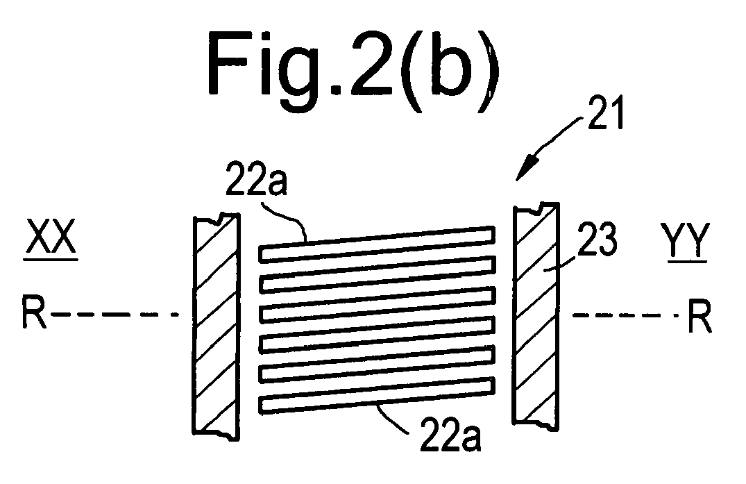
- Fig. 2b relates to a cross-section in the direction CC depicted in Fig. 2a
- Fig. 2d relates to a cross section DD depicted in Fig. 2c .
- the arrangement 21 depicted in Fig. 2 is similar to that depicted in Fig. 1 .
- the leaf seals 22 are configured at an askew angle relative to an axis of rotation R-R for the surface 24. In such circumstances the deflection characteristics are different with the present arrangement.
- Fig. 2a and Fig. 2b illustrates the seal arrangement 21 in a non displaced position in which the arrangement 21 is at rest or there is insufficient fluid or pressure differential between a high pressure side XX and a low pressure side YY.
- a clearance 26 between the tip end 25 and the surface 24 is controlled in order to provide an effective seal with only marginal leakage through the gap 26 across the arrangement 21 between the high pressure side XX and the low pressure side YY.
- There is limited leakage flow and of a relatively low force such that the skew angle or tilt of the leaf seals 22a causes no deflection or displacement of the leaf seals 22.
- an askew angle allows assembly with the leaf in an initial first position, that is to say with the leaf against the front plate, but if lift up becomes excessive cause blow down by premature (in comparison with prior arrangements) engagement with the backing plate.
- the askew presentation also causes a drag on the flow which alters the clearance gap between the leaves 22 and cover plate 29 such that the tip end 25 may be displaced from the inlet side 30 towards the outlet side 31.
- judicious choice of the skew angle of the leaf seals 22 relative to the axis of rotation it will be understood that it is possible to control, and provide an optimum operational position for the leaf seals 22 in use.
- the askew angle will be dependent upon the materials and flexibility of the leaf seals 22. As indicated above, wear resistance and achievement of an acceptable seal with a seal arrangement can be counter intuitive. However, by provision of an askew angle relative to the axis of rotation RR it will be understood that a further controlled parameter is provided to allow specific adjustment to achieve optimum performance for design which extends the feasible performance criteria for acceptable materials and leaf seal thicknesses.
- the leaf thickness in the arrangement 21 of the present invention is not only used radially but also axially in displacing the tip end 25 and therefore as indicated provides a further approach with respect to controlling tip end 25 position and therefore good sealing performance with minimal risk of wear on the leaf seals 22 in contact with the rotating source 24.
- leaf seals may be profiled and non-rectangular in shape.
- the leaf seal may have a chamfered or truncated corner removed at an askew angle in order to further enhance the leaf deflection and control.
- Such chamfering of the edge or corner of a leaf seal is illustrated by potential removal of part of the leaf seal along an edge depicted by broken line 40 in Fig. 2 .
- the leading edge of the leaf seal might have a differing operational performance in comparison with a substantially rectangular leaf seal element.
Landscapes
- Engineering & Computer Science (AREA)
- General Engineering & Computer Science (AREA)
- Mechanical Engineering (AREA)
- Turbine Rotor Nozzle Sealing (AREA)
- Sealing Devices (AREA)
Abstract


Description
- The present invention relates to a seal arrangement and more particularly to so called leaf seal arrangements utilised to provide a seal about a rotating component between a high pressure side and relatively low pressure side.
- Traditionally seal arrangements have been provided utilising brush seals which achieve a close clearance and radially compliant seal about a rotating component. A disadvantage with a brush seal is that the bristles at high differential pressures exhibit two forms of behaviour which may limit their operational life. Firstly, during a so called blow down condition the bristles are caused to rub hard against the rotor whilst the tendency of the pressure force to lock the bristles against a sealed backing ring again limits flexibility with regard to movement in order to accommodate rotor component excursions. These effects upon bristle seal arrangements can cause premature wear of the seal and reduce its effective life.
- More recently leaf seals have been designed to address the limitations of brush seal arrangements and particularly with respect to excessive wear. Leaf seals essentially comprise metal leaves which are substituted for bristles in a seal arrangement. The leaves are compliant in a radial direction but stiff in the axial direction. In such circumstances there is a reduction in the tendency for the leaf seal to lock in position as pressure is applied and therefore wearing of the leaves is reduced.
-
U.K. patent application No. 99300090.0 - In accordance with the present invention there is provided a seal arrangement for a rotating component, the arrangement comprising a plurality of leaf seals projecting radially inward towards a rotating surface at a skew angle away from alignment with an axis of rotation for the rotating surface.
- Generally, the arrangement has a relatively high pressure on one side compared to the other side of the leaf seals in use.
- Normally, the leaf seals have a substantially rectangular cross section. Alternatively, the leaf seals have a chamfered edge or corner.
- Possibly, the leaf seals have a clearance gap between the rotating surface through which there is a fluid flow in use which may deflect the leaf seals. Possibly, the skew angle is determined to provide a desired asymmetric deflection of the leaf seals. Advantageously, the asymmetric deflection alters an inlet flow area relative to an exit flow area of the leaf seals.
- Alternatively, or additionally, the asymmetric deflection shifts axial positioning of tip end of the leaf seals relative to the rotating surface.
- Generally, the leaf seals are presented in a housing about the rotating surface and juxtaposed next to each other.
- Possibly, the leaf seals are arranged to engage a front or cover plate of the housing in order to bias the leaf seals towards lift up when subject in use to a cross flow due to a pressure differential and the bias towards lift up is limited by the skew angle providing engagement with a backing plate of the housing to precipitate blow down of the leaf seals.
- Additionally, the value of the skew angle is determined to provide balance between lift up and blow down of the leaf seals in use.
- An embodiment of the present invention will now be described by way of example with reference to the accompanying drawings in which:
-
Fig. 1 provides a schematic illustration of a prior seal arrangement utilising leaf seals in a non-displaced and a displaced operational condition; and, -
Fig. 2 is a schematic illustration of a seal arrangement in accordance with the present invention in a non displaced and displaced operational condition. - As indicated above, leaf seal arrangements are known. Thus, as illustrated in
Fig. 1 a conventional seal arrangement 1 comprises a plurality of leaf seals 2 which are secured in ahousing 3 relative to a rotating surface 4. The operational position of the arrangement 1 is depicted in its non displaced state, that is to say where deflection of the leaf seals 2 has not occurred inFigs. 1a, 1b whilst inFigs. 1c, 1d deflection of the leaf seals 2 is caused by fluid flow in use across the leaf seals 2.Fig. 1b illustrates in schematic plan view theleaf seals 2a in the cross-section AA depicted inFig. 1a . The leaf seals are of a conventional rectangular cross-section and, as can be seen, abottom tip end 5 is presented towards the rotating surface 4. A clearance gap 6 is chosen to limit the leakage fluid flow across the seal arrangement 1 from a high pressure side X to a low pressure side Y. Lift off and blow down characteristics are primarily controlled by axial gaps between the leaf seals 2 and thehousing 3. Furthermore, the leaf seal 2 has lift up and blow down characteristics which are influenced by fluid flow entry and exit constraints presented by theend 5 relative to the surface 4 which in turn affects the clearance gap 6. - In a conventional arrangement depicted in
Fig. 1 the entry and exit constraints are governed by the radial and axial clearance of the leaf seals 2. As indicated in use there will generally be a high pressure differential between side X and side Y which drives a fluid flow across the leaf seal surface and between axial gaps between leaf seals in the housing of this fluid flow which in turn deflects the leaf seals 2. As the leaf seal 22 flexes or is deflected by the fluid flow in a conventional leaf seal arrangement 1 as depicted inFig. 1 the fluid entry or exit conditions remain essentially constant so the radial aero dynamic forces are also constant and balanced across the leaf stiffness at deflection. - In the above circumstances, as can be seen in a comparison between respectively
Fig. 1a withFig. 1c and Fig. 1b and Fig. 1d , it will be noted that the leaf seals 2 are deflected and flexed from an un-displaced configuration inFig. 1a and Fig. 1b shown as theleaf seals 2a and the displaced or flexedleaf seals 2c shown inFig. 1c and Fig. 1d . In such circumstances a displacedclearance gap 7 is created between the bottom of the displacedleaf seal 2c and the rotating surface 4. - In the conventional arrangement 1 depicted in
Fig. 1 it will be appreciated that there is symmetry in the deflection of the leaf seals 2. There is no active control in order to optimise the wear characteristics and performance for the arrangement 1. Ideally, control should be provided to use the fluid flow in order to adjust the seal lift deflection for good performance in terms of wear and sealing efficiency. Such control relates to the clearance for flow between leaves and their housing and as well as across leaves in the gaps between them as well as in relation to theleaf tip edge 5 load pressure which will be presented to the rotating surface 4 in terms of lift up or blow down characteristics. -
Fig. 2 illustrates aseal arrangement 21 in accordance with the present invention. Thus, as previously leaf seals 22 have a generally rectangular cross-section which projects radially towards a rotatingsurface 24 in ahousing 23.Fig. 2b relates to a cross-section in the direction CC depicted inFig. 2a , whilstFig. 2d relates to a cross section DD depicted inFig. 2c . In such circumstances in radially projecting seals 22 towards thesurface 24 thearrangement 21 depicted inFig. 2 is similar to that depicted inFig. 1 . However, it will be noted that the leaf seals 22 are configured at an askew angle relative to an axis of rotation R-R for thesurface 24. In such circumstances the deflection characteristics are different with the present arrangement. - As the leaf seals 22 are no longer aligned with the axis of rotation RR, it will be understood that deflecting each individual leaf 22 will increase or decrease the clearance between the leaf seal 22 and
cover plates 29 of thehousing 23. In short, the fluid flow through the gap between leaves and with thehousing 23 will cause asymmetric deflection of the leaf seals 22 between aninlet side 30 and anoutlet side 31. Thus, the inlet and exit flow areas will change and the lift up/blow down forces can be controlled to provide an optimum running position for the leaf seals 22 as an assembly about thesurface 24. - By presenting leaf seals at an askew angle relative to an axis of rotation R R asymmetric deflection is achieved between an inlet side and an exit side such that the inlet and exit flow areas change and therefore lift up/blow down forces can be controlled to achieve a more optimal positioning of a tip end relative to a rotating surface for operational performance with reduced risk of wear upon the leaf seals.
-
Fig. 2a and Fig. 2b illustrates theseal arrangement 21 in a non displaced position in which thearrangement 21 is at rest or there is insufficient fluid or pressure differential between a high pressure side XX and a low pressure side YY. In such circumstances, as can be seen, aclearance 26 between thetip end 25 and thesurface 24 is controlled in order to provide an effective seal with only marginal leakage through thegap 26 across thearrangement 21 between the high pressure side XX and the low pressure side YY. There is limited leakage flow and of a relatively low force such that the skew angle or tilt of the leaf seals 22a causes no deflection or displacement of the leaf seals 22. - When there is sufficient pressure differential between side XX and side YY across the
arrangement 21 there will be more driving forces as a result of the fluid flow between leaves and the leaves and the housing to cause deflection of the leaf seals 22c. This deflection is due to the askew presentation of the leaf seals 22c to the axis for rotation R-R. It will be understood that if a leaf positioned in abutment with the cover orfront plate 29 of a housing it will tend to lift up even without an askew presentation angle due to turning in the flow. However, if the leaf is pushed against a backing plate of a housing it will tend to blow down causing wear. Provision of an askew angle allows assembly with the leaf in an initial first position, that is to say with the leaf against the front plate, but if lift up becomes excessive cause blow down by premature (in comparison with prior arrangements) engagement with the backing plate. The askew presentation also causes a drag on the flow which alters the clearance gap between the leaves 22 andcover plate 29 such that thetip end 25 may be displaced from theinlet side 30 towards theoutlet side 31. In. such circumstances by judicious choice of the skew angle of the leaf seals 22 relative to the axis of rotation it will be understood that it is possible to control, and provide an optimum operational position for the leaf seals 22 in use. - It will be understood that the askew angle will be dependent upon the materials and flexibility of the leaf seals 22. As indicated above, wear resistance and achievement of an acceptable seal with a seal arrangement can be counter intuitive. However, by provision of an askew angle relative to the axis of rotation RR it will be understood that a further controlled parameter is provided to allow specific adjustment to achieve optimum performance for design which extends the feasible performance criteria for acceptable materials and leaf seal thicknesses.
- It will be understood that the
individual leaf seals 22c will flex through the fluid flow in theclearance 27 as well as the spacing between the leaf seals 22. Essentially, by providing an askew angle for the leaf seals 22 it will be appreciated that fluid flow X in the gap or spacing between the leaf seals 22 is deflected by entrainment but the flow X presents loadings from the individual leaf seals 22 which cause distortion across the leaf seals 22 from theinlet side 30 to theexit side 31. In such circumstances the leaf thickness in thearrangement 21 of the present invention is not only used radially but also axially in displacing thetip end 25 and therefore as indicated provides a further approach with respect to controllingtip end 25 position and therefore good sealing performance with minimal risk of wear on the leaf seals 22 in contact with therotating source 24. - Modifications and alterations to the present invention will be understood by those skilled in the art. Thus, rather than providing rectangular leaf seals as described above it will be appreciated that the leaf seals may be profiled and non-rectangular in shape. In such circumstances, the leaf seal may have a chamfered or truncated corner removed at an askew angle in order to further enhance the leaf deflection and control.
- Such chamfering of the edge or corner of a leaf seal is illustrated by potential removal of part of the leaf seal along an edge depicted by
broken line 40 inFig. 2 . Thus, the leading edge of the leaf seal might have a differing operational performance in comparison with a substantially rectangular leaf seal element.
Claims (12)
- A seal arrangement (21) for a rotating component, the arrangement comprising a plurality of leaf seals (22) projecting radially inward towards a rotating surface (24) at a skew angle away from alignment with an axis of rotation (R-R) for the rotating surface (24).
- An arrangement as claimed in claim 1 wherein the arrangement has a relatively high pressure on one side compared to the other side of the leaf seals in use.
- An arrangement as claimed in claim 1 or claim 2 wherein the leaf seals have a substantially rectangular cross section.
- An arrangement as claimed in claim 1 or claim 2 where the leaf seals have a chamfered edge or corner.
- An arrangement as claimed in any preceding claim wherein the leaf seals have a clearance gap between the leaf seals and the rotating surface through which there may be a fluid flow in use which may deflect the leaf seals.
- An arrangement as claimed in any preceding claim wherein the askew angle is determined to provide a desired asymmetric deflection of the leaf seals.
- An arrangement as claimed in claim 6 wherein the asymmetric deflection alters an inlet flow area relative to an exit flow area of the leaf seals.
- An arrangement as claimed in claim 6 or claim 7 wherein the asymmetric deflection shifts axial positioning of tip end of the leaf seals relative to the rotating surface.
- An arrangement as claimed in any preceding claim wherein the leaf seals are presented in a housing about the rotating surface and juxtaposed next to each other.
- An arrangement as claimed in claim 9 wherein the leaf seals are arranged to engage a front or cover plate of the housing in order to bias the leaf seals towards lift up when subject in use to a cross flow due to a pressure differential and the bias towards lift up is limited by the skew angle providing engagement with a backing plate of the housing to precipitate blow down of the leaf seals.
- An arrangement as claimed in claim 10 wherein the value of the skew angle is determined to provide balance between lift up and blow down of the leaf seals in use.
- A gas turbine engine incorporating a seal arrangement as claimed in any preceding claim.
Applications Claiming Priority (1)
| Application Number | Priority Date | Filing Date | Title |
|---|---|---|---|
| GBGB0707224.2A GB0707224D0 (en) | 2007-04-14 | 2007-04-14 | A seal arrangement |
Publications (1)
| Publication Number | Publication Date |
|---|---|
| EP1980718A1 true EP1980718A1 (en) | 2008-10-15 |
Family
ID=38116735
Family Applications (1)
| Application Number | Title | Priority Date | Filing Date |
|---|---|---|---|
| EP08250901A Withdrawn EP1980718A1 (en) | 2007-04-14 | 2008-03-15 | A seal arrangement |
Country Status (4)
| Country | Link |
|---|---|
| US (1) | US20080309018A1 (en) |
| EP (1) | EP1980718A1 (en) |
| JP (1) | JP2008261498A (en) |
| GB (1) | GB0707224D0 (en) |
Cited By (2)
| Publication number | Priority date | Publication date | Assignee | Title |
|---|---|---|---|---|
| EP2138747A1 (en) * | 2008-06-25 | 2009-12-30 | Rolls-Royce plc | A sealing device |
| DE102010050728B4 (en) | 2009-11-11 | 2024-01-18 | Ansaldo Energia Switzerland AG | Lamella seal |
Families Citing this family (10)
| Publication number | Priority date | Publication date | Assignee | Title |
|---|---|---|---|---|
| GB0417613D0 (en) * | 2004-08-07 | 2004-09-08 | Rolls Royce Plc | A leaf seal arrangement |
| EP2444701B1 (en) * | 2009-06-16 | 2020-07-01 | Mitsubishi Hitachi Power Systems, Ltd. | Shaft seal device |
| US8932001B2 (en) * | 2011-09-06 | 2015-01-13 | General Electric Company | Systems, methods, and apparatus for a labyrinth seal |
| JP6012505B2 (en) * | 2013-02-22 | 2016-10-25 | 三菱重工業株式会社 | Shaft seal device and rotary machine |
| JP6358976B2 (en) | 2015-02-20 | 2018-07-18 | 三菱日立パワーシステムズ株式会社 | Turbine sealing device and turbine, and thin plate for sealing device |
| JP6678062B2 (en) * | 2016-05-09 | 2020-04-08 | 三菱日立パワーシステムズ株式会社 | Seal segment and rotating machine |
| JP6675262B2 (en) | 2016-05-09 | 2020-04-01 | 三菱日立パワーシステムズ株式会社 | Seal segment and rotating machine |
| JP6631837B2 (en) | 2016-05-09 | 2020-01-15 | 三菱日立パワーシステムズ株式会社 | Seal segment and rotating machine |
| JP6876012B2 (en) | 2018-02-19 | 2021-05-26 | 三菱パワー株式会社 | Seal segment and rotating machine |
| US20240183445A1 (en) * | 2022-12-01 | 2024-06-06 | Ut-Battelle, Llc | High-efficiency seal composed of carbon nanotubes |
Citations (6)
| Publication number | Priority date | Publication date | Assignee | Title |
|---|---|---|---|---|
| GB933567A (en) | 1961-06-02 | 1963-08-08 | Ferranti Ltd | Improvements relating to flying spot storage devices |
| EP0933567A2 (en) * | 1998-01-30 | 1999-08-04 | Rolls-Royce Plc | A seal arrangement |
| EP1013975A1 (en) * | 1998-07-13 | 2000-06-28 | Mitsubishi Heavy Industries, Ltd. | Shaft seal and turbine using the shaft seal |
| EP1302708A2 (en) * | 2001-10-09 | 2003-04-16 | Mitsubishi Heavy Industries, Ltd. | Shaft seal mechanism and turbine |
| US20030071423A1 (en) * | 2000-02-12 | 2003-04-17 | Karl Urlichs | Rotor seal with folding strip |
| WO2006016098A1 (en) * | 2004-08-07 | 2006-02-16 | Rolls-Royce Plc | A leaf seal arrangement |
Family Cites Families (2)
| Publication number | Priority date | Publication date | Assignee | Title |
|---|---|---|---|---|
| US4526509A (en) * | 1983-08-26 | 1985-07-02 | General Electric Company | Rub tolerant shroud |
| GB8907695D0 (en) * | 1989-04-05 | 1989-05-17 | Cross Mfg Co | Seals |
-
2007
- 2007-04-14 GB GBGB0707224.2A patent/GB0707224D0/en not_active Ceased
-
2008
- 2008-03-15 EP EP08250901A patent/EP1980718A1/en not_active Withdrawn
- 2008-03-18 US US12/076,419 patent/US20080309018A1/en not_active Abandoned
- 2008-04-10 JP JP2008102022A patent/JP2008261498A/en not_active Withdrawn
Patent Citations (6)
| Publication number | Priority date | Publication date | Assignee | Title |
|---|---|---|---|---|
| GB933567A (en) | 1961-06-02 | 1963-08-08 | Ferranti Ltd | Improvements relating to flying spot storage devices |
| EP0933567A2 (en) * | 1998-01-30 | 1999-08-04 | Rolls-Royce Plc | A seal arrangement |
| EP1013975A1 (en) * | 1998-07-13 | 2000-06-28 | Mitsubishi Heavy Industries, Ltd. | Shaft seal and turbine using the shaft seal |
| US20030071423A1 (en) * | 2000-02-12 | 2003-04-17 | Karl Urlichs | Rotor seal with folding strip |
| EP1302708A2 (en) * | 2001-10-09 | 2003-04-16 | Mitsubishi Heavy Industries, Ltd. | Shaft seal mechanism and turbine |
| WO2006016098A1 (en) * | 2004-08-07 | 2006-02-16 | Rolls-Royce Plc | A leaf seal arrangement |
Cited By (2)
| Publication number | Priority date | Publication date | Assignee | Title |
|---|---|---|---|---|
| EP2138747A1 (en) * | 2008-06-25 | 2009-12-30 | Rolls-Royce plc | A sealing device |
| DE102010050728B4 (en) | 2009-11-11 | 2024-01-18 | Ansaldo Energia Switzerland AG | Lamella seal |
Also Published As
| Publication number | Publication date |
|---|---|
| JP2008261498A (en) | 2008-10-30 |
| GB0707224D0 (en) | 2007-05-23 |
| US20080309018A1 (en) | 2008-12-18 |
Similar Documents
| Publication | Publication Date | Title |
|---|---|---|
| EP1980718A1 (en) | A seal arrangement | |
| US7419164B2 (en) | Compliant plate seals for turbomachinery | |
| EP2318738B1 (en) | Leaf seal | |
| US8382119B2 (en) | Compliant plate seals for turbomachinery | |
| US20070018408A1 (en) | Strip brush seal | |
| EP1900983B1 (en) | Shaft seal using shingle compliant-plate members | |
| US5884918A (en) | Brush seal with a flexible front plate | |
| US8100404B2 (en) | Leaf seal arrangement | |
| US7980562B2 (en) | Seal arrangement | |
| EP1608900B1 (en) | A seal arrangement | |
| EP2669556A1 (en) | A leaf seal | |
| EP1998085A1 (en) | Static outside diameter brush seal assembly | |
| EP2604894B1 (en) | Improved leaf seal | |
| JP5032597B2 (en) | sticker | |
| US20030194312A1 (en) | Flush tenon cover for steam turbine blades with advanced sealing | |
| WO1997014897A2 (en) | A brush seal with a flexible front plate | |
| WO1997014897A9 (en) | A brush seal with a flexible front plate | |
| EP3045785B1 (en) | Shaft sealing device and rotating machine provided therewith | |
| CN217207373U (en) | Oil scraper ring and bearing seal with oil scraper ring |
Legal Events
| Date | Code | Title | Description |
|---|---|---|---|
| PUAI | Public reference made under article 153(3) epc to a published international application that has entered the european phase |
Free format text: ORIGINAL CODE: 0009012 |
|
| 17P | Request for examination filed |
Effective date: 20080812 |
|
| AK | Designated contracting states |
Kind code of ref document: A1 Designated state(s): AT BE BG CH CY CZ DE DK EE ES FI FR GB GR HR HU IE IS IT LI LT LU LV MC MT NL NO PL PT RO SE SI SK TR |
|
| AX | Request for extension of the european patent |
Extension state: AL BA MK RS |
|
| 17Q | First examination report despatched |
Effective date: 20081124 |
|
| AKX | Designation fees paid |
Designated state(s): CH DE FR GB LI |
|
| STAA | Information on the status of an ep patent application or granted ep patent |
Free format text: STATUS: THE APPLICATION IS DEEMED TO BE WITHDRAWN |
|
| 18D | Application deemed to be withdrawn |
Effective date: 20090407 |