EP2138747A1 - A sealing device - Google Patents
A sealing device Download PDFInfo
- Publication number
- EP2138747A1 EP2138747A1 EP09250799A EP09250799A EP2138747A1 EP 2138747 A1 EP2138747 A1 EP 2138747A1 EP 09250799 A EP09250799 A EP 09250799A EP 09250799 A EP09250799 A EP 09250799A EP 2138747 A1 EP2138747 A1 EP 2138747A1
- Authority
- EP
- European Patent Office
- Prior art keywords
- leaf
- sealing device
- tip
- centre
- gap
- Prior art date
- Legal status (The legal status is an assumption and is not a legal conclusion. Google has not performed a legal analysis and makes no representation as to the accuracy of the status listed.)
- Withdrawn
Links
Images

Classifications
-
- F—MECHANICAL ENGINEERING; LIGHTING; HEATING; WEAPONS; BLASTING
- F01—MACHINES OR ENGINES IN GENERAL; ENGINE PLANTS IN GENERAL; STEAM ENGINES
- F01D—NON-POSITIVE DISPLACEMENT MACHINES OR ENGINES, e.g. STEAM TURBINES
- F01D11/00—Preventing or minimising internal leakage of working-fluid, e.g. between stages
- F01D11/003—Preventing or minimising internal leakage of working-fluid, e.g. between stages by packing rings; Mechanical seals
-
- F—MECHANICAL ENGINEERING; LIGHTING; HEATING; WEAPONS; BLASTING
- F01—MACHINES OR ENGINES IN GENERAL; ENGINE PLANTS IN GENERAL; STEAM ENGINES
- F01D—NON-POSITIVE DISPLACEMENT MACHINES OR ENGINES, e.g. STEAM TURBINES
- F01D11/00—Preventing or minimising internal leakage of working-fluid, e.g. between stages
-
- F—MECHANICAL ENGINEERING; LIGHTING; HEATING; WEAPONS; BLASTING
- F04—POSITIVE - DISPLACEMENT MACHINES FOR LIQUIDS; PUMPS FOR LIQUIDS OR ELASTIC FLUIDS
- F04D—NON-POSITIVE-DISPLACEMENT PUMPS
- F04D29/00—Details, component parts, or accessories
- F04D29/08—Sealings
- F04D29/10—Shaft sealings
-
- F—MECHANICAL ENGINEERING; LIGHTING; HEATING; WEAPONS; BLASTING
- F16—ENGINEERING ELEMENTS AND UNITS; GENERAL MEASURES FOR PRODUCING AND MAINTAINING EFFECTIVE FUNCTIONING OF MACHINES OR INSTALLATIONS; THERMAL INSULATION IN GENERAL
- F16J—PISTONS; CYLINDERS; SEALINGS
- F16J15/00—Sealings
- F16J15/16—Sealings between relatively-moving surfaces
- F16J15/32—Sealings between relatively-moving surfaces with elastic sealings, e.g. O-rings
- F16J15/3284—Sealings between relatively-moving surfaces with elastic sealings, e.g. O-rings characterised by their structure; Selection of materials
- F16J15/3288—Filamentary structures, e.g. brush seals
-
- F—MECHANICAL ENGINEERING; LIGHTING; HEATING; WEAPONS; BLASTING
- F16—ENGINEERING ELEMENTS AND UNITS; GENERAL MEASURES FOR PRODUCING AND MAINTAINING EFFECTIVE FUNCTIONING OF MACHINES OR INSTALLATIONS; THERMAL INSULATION IN GENERAL
- F16J—PISTONS; CYLINDERS; SEALINGS
- F16J15/00—Sealings
- F16J15/16—Sealings between relatively-moving surfaces
- F16J15/32—Sealings between relatively-moving surfaces with elastic sealings, e.g. O-rings
- F16J15/3284—Sealings between relatively-moving surfaces with elastic sealings, e.g. O-rings characterised by their structure; Selection of materials
- F16J15/3292—Lamellar structures
-
- F—MECHANICAL ENGINEERING; LIGHTING; HEATING; WEAPONS; BLASTING
- F05—INDEXING SCHEMES RELATING TO ENGINES OR PUMPS IN VARIOUS SUBCLASSES OF CLASSES F01-F04
- F05D—INDEXING SCHEME FOR ASPECTS RELATING TO NON-POSITIVE-DISPLACEMENT MACHINES OR ENGINES, GAS-TURBINES OR JET-PROPULSION PLANTS
- F05D2240/00—Components
- F05D2240/55—Seals
- F05D2240/57—Leaf seals
Definitions
- This invention relates to a sealing device for providing a seal in a gap between first and second components, and is particularly, although not exclusively, concerned with such a device for sealing a gap between a stationary component and a rotating component in a gas turbine engine.
- EP 0933567 discloses a leaf seal for use in a gas turbine engine, which comprises a densely packed array of thin resilient strips which are held by an annular carrier fixed to a stationary component of the gas turbine engine.
- the strips project inwardly from the carrier to contact, or terminate close to, a rotating shaft of the engine.
- the strips are inclined to the radial direction and can flex in response to radial movement or dimensional change of the shaft so that, together, they maintain a densely packed structure within the gap between the stationary component and the shaft, so as to support a pressure difference across the gap.
- Each strip, or leaf has a leading edge exposed to the high pressure side of the gap and a trailing edge exposed to the low pressure side.
- the plane of each leaf may be aligned with the axial direction of the shaft, or may be inclined to this direction.
- one or more of the leaves may exhibit flutter.
- flutter is meant an unstable portional oscillation of the leaf about an axis extending in the lengthwise direction of the leaf, ie from the fixed end of the leaf held by the carrier and the tip of the leaf adjacent the shaft. Flutter is damaging, and will often ruin the seal. Flutter usually starts locally within the seal; the affected leaves flap with considerable energy and hit adjacent leaves causing damage. If a number of leaves become damaged, the seal with deteriorate. The onset of flutter usually occurs very rapidly.
- a sealing device for providing a seal in a gap between first and second components, the sealing device comprising an array of leaves, each leaf extending across the gap from a fixed end which is supported with respect to the first component to a tip which contacts or is adjacent to a surface of the second component, each leaf having a leading edge, with respect to the flow direction through the gap, which extends from a first point at the fixed end to a second point at the tip, and having a torsional axis extending from the fixed end to the tip, characterised in that the second point is disposed downstream of the first point with respect to the flow direction, such that the chordwise position of the centre of pressure at the tip is at or downstream of the chordwise position of the torsional axis at the tip.
- At least part of the leading edge of each leaf may be substantially straight, and in one embodiment, at least part of the leading edge of each leaf is inclined in the flow direction to the perpendicular direction between the first and second components.
- the leading edge may be inclined over its full extent from the fixed end to the tip of the leaf.
- each leaf may be substantially straight, and may, over at least part of its length, be inclined in the flow direction to the perpendicular direction between the first and second components. At least part of the trailing edge may be inclined in the upstream direction to the perpendicular direction between the first and second components.
- the trailing edge has a first portion which extends from the fixed end in a direction inclined in the flow direction to the perpendicular direction between the first and second components, and a second portion which extends from the first portion to the tip and is inclined in the upstream direction to the perpendicular direction between the first and second components.
- the present invention also provides an assembly comprising a stationary component and a rotor which is rotatable relative to the stationary component, and a sealing device as defined above, the sealing device providing a seal in a gap between the stationary component and the rotor.
- Another aspect of the present invention provides a gas turbine engine including an assembly as defined above.
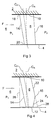
- FIG. 1 is a view in the axial direction of the rotating component 4, and consequently the surface of the component 4 visible in Figure 1 , and the oppositely facing surface of the component 2 are, in reality, curved as viewed in Figure 1 , and are represented as straight lines only for the sake of simplicity.
- a gap 6 is left between the fixed component 2 and the rotating component 4.
- This gap 6 is sealed by means of a leaf seal which comprises densely packed flexible leaves 8, for example of steel, which are each fixed at one end 10 to a carrier secured to the fixed component 2.
- the other end, or tip 12, of each leaf 8 contacts, or at least lies close to, the surface of the rotating component 4.
- the leaves 8 are inclined to the perpendicular direction across the gap 6 in a direction corresponding to the direction of rotation R of the rotating component 4.
- the leaves 8 are shown spaced slightly apart from each other, but in practice they will contact one another over at least part of their lengths, so as to seal across the gap 6 and support a pressure difference between a pressure P 1 and a lower pressure P 2 , as shown in Figure 2 .
- a conventional leaf 8 is generally rectangular, having leading and trailing edges 14, 16 which lie in respective planes which extend radially of the axis (not shown) of the rotating component 4.
- the leading edge 14 is exposed to the higher pressure P 1 while the trailing edge 16 is exposed to the lower pressure P 2 .
- the respective edges 14 and 16 are leading and trailing with respect to the direction of flow across the seal.
- Each leaf 8 is clamped rigidly by the carrier which is fixed to the stationary component 2.
- Each leaf 8 has a centre of torsion, or centre of rotation, C R which is determined by the geometry of the leaf 8.
- the centre of torsion C R is the axis which experiences no displacement when the tip 12 is twisted relatively to the fixed end 10. In general, the centre of torsion C R is at or close to the geometric centreline of the leaf 8.
- Each leaf 8 also has a centre of pressure C P which is the position, in the chordwise direction of the leaf 8, at which acts the pressure generated by an airflow over the leaf 8.
- the centre of pressure C P is situated approximately 25% of the chordwise width of the leaf 8 from the leading edge 14.
- Figure 3 shows an embodiment of a leaf 8 for a leaf seal in accordance with the present invention.
- the leaf 8 remains of quadrilateral form, but is no longer rectangular. Instead, the leading edge 14 is inclined to the perpendicular direction between the fixed component 2 and the rotating component 4 so that the tip point 20 is downstream of the fixed point 18, with respect to the flow direction F.
- the trailing edge 16 is also inclined in the same manner as the leading edge 14, although at a smaller angle to the perpendicular distance between the stationary component 2 and the rotating component 4. Consequently, the leaf 8 as a whole has a generally swept back configuration, in that the leaf 8 is inclined in the downstream direction F from the stationary component 2 to the rotating component 4.
- Figure 3 indicates the effect which the changed leaf geometry has on the relative positions of the centre of torsion C R and the centre of pressure C P .
- the centre of pressure C P is now situated downstream of the centre of rotation C R . Consequently, at the tip 12, and in the region of the blade between the tip 12 and the point of intersection between the centre of pressure and centre of torsion lines C P and C R , the centre of pressure C P is downstream of the centre of torsion C R . Consequently, the air flow over the leaf 8 in this region will tend to correct any deviation of the leaf 8 from alignment with the airflow F, so damping any tendency to flutter.
- the required relationship between the centre of pressure C P and the centre of torsion C R can be achieved with configurations of the leading and trailing edges 14,16 different from those shown in Figure 3 .
- the trailing edge 16 could remain parallel to the perpendicular distance between the stationary component 2 and the rotating component 4, or only part of it could be inclined.
- the leading edge 14 need not be continuously inclined between the fixed point 18 and the tip point 20.
- the leading edge 14 could be curved, or made up of sections of different angles of inclination.
- Figure 4 shows an alternative embodiment of the leaf 8.
- the leading edge 14 is similar to that of Figure 3 , but which has a trailing edge 16 made up of first and second sections 22, 24.
- the first section 22 is generally parallel to the leading edge 14 while the second section 24 is inclined in the opposite direction from that of the section 22, ie it is directed upstream with respect to the flow direction F so as to reduce the chordwise width of the leaf 8 at the tip 12.
- the leading edge 14 is similar to that of Figure 3, and Figure 4 illustrates that the required profile can be achieved by cutting away a triangular section 26 from a leaf 8 having a rectangular profile as shown in Figure 2 , at least in the region of the leading edge 14.
- Figure 4 also illustrates how the section 24 can be achieved by cutting away a triangular section 28 from a leaf as shown in Figure 3 , but with a greater angle of inclination of the trailing edge 16.
- the geometry of the leaf 8 has the effect that the centre of torsion C R curves in the downstream direction, with reference to the flow direction F, as it approaches the tip 12.
- the centre of pressure C P initially extends parallel to the leading edge 14, but, owing to the upstream directed section 24 of the trailing edge 16, is deflected towards the leading edge 14, so as to end, at the tip 12, in approximately the same position as the centre of torsion C R .
- the centre of pressure C P and the centre of torsion C R can be made to coincide in the region of the tip 12.
- the stability of the leaf 8 can be adjusted so as to avoid flutter while maintaining adequate sealing performance.
- the centre of torsion C R is dominated by the fixing of the leaf 8 at its fixed end 10 but nevertheless will tend to curve in the downstream direction, with reference to the flow direction F, as a result of the downstream sweep of the leaf 8.
- the centre of pressure C P extends parallel to the leading edge 14 of the leaf 8 from the fixed end 10 to the tip 12.
- the amount of curvature of the centre of torsion C R in the downstream direction with respect to the centre of pressure C P is such that, in the region of the tip 12, the chordwise position of the centre of pressure C P is at, or downstream of the centre of torsion C R .
- the geometry of the leaf 8 can be manipulated such that the stability of the leaf 8 can be adjusted so as to avoid flutter while maintaining adequate sealing performance.
Abstract
Description
- This invention relates to a sealing device for providing a seal in a gap between first and second components, and is particularly, although not exclusively, concerned with such a device for sealing a gap between a stationary component and a rotating component in a gas turbine engine.
-
EP 0933567 discloses a leaf seal for use in a gas turbine engine, which comprises a densely packed array of thin resilient strips which are held by an annular carrier fixed to a stationary component of the gas turbine engine. The strips project inwardly from the carrier to contact, or terminate close to, a rotating shaft of the engine. The strips are inclined to the radial direction and can flex in response to radial movement or dimensional change of the shaft so that, together, they maintain a densely packed structure within the gap between the stationary component and the shaft, so as to support a pressure difference across the gap. - Each strip, or leaf, has a leading edge exposed to the high pressure side of the gap and a trailing edge exposed to the low pressure side. The plane of each leaf may be aligned with the axial direction of the shaft, or may be inclined to this direction.
- In some circumstances, one or more of the leaves may exhibit flutter. By flutter is meant an unstable portional oscillation of the leaf about an axis extending in the lengthwise direction of the leaf, ie from the fixed end of the leaf held by the carrier and the tip of the leaf adjacent the shaft. Flutter is damaging, and will often ruin the seal. Flutter usually starts locally within the seal; the affected leaves flap with considerable energy and hit adjacent leaves causing damage. If a number of leaves become damaged, the seal with deteriorate. The onset of flutter usually occurs very rapidly.
- According to the present invention, there is provided a sealing device for providing a seal in a gap between first and second components, the sealing device comprising an array of leaves, each leaf extending across the gap from a fixed end which is supported with respect to the first component to a tip which contacts or is adjacent to a surface of the second component, each leaf having a leading edge, with respect to the flow direction through the gap, which extends from a first point at the fixed end to a second point at the tip, and having a torsional axis extending from the fixed end to the tip, characterised in that the second point is disposed downstream of the first point with respect to the flow direction, such that the chordwise position of the centre of pressure at the tip is at or downstream of the chordwise position of the torsional axis at the tip.
- By appropriate configuration of the leaf, particularly with regard to the leading edge, the relationship between the chordwise positions of the centre of pressure and the torsional axis at the tip of the leaf can result in the leaf being stable when air flows through the gap between the high and low pressure regions. Consequently, flutter will be inhibited.
- At least part of the leading edge of each leaf may be substantially straight, and in one embodiment, at least part of the leading edge of each leaf is inclined in the flow direction to the perpendicular direction between the first and second components. The leading edge may be inclined over its full extent from the fixed end to the tip of the leaf.
- The trailing edge of each leaf may be substantially straight, and may, over at least part of its length, be inclined in the flow direction to the perpendicular direction between the first and second components. At least part of the trailing edge may be inclined in the upstream direction to the perpendicular direction between the first and second components. In a specific embodiment, the trailing edge has a first portion which extends from the fixed end in a direction inclined in the flow direction to the perpendicular direction between the first and second components, and a second portion which extends from the first portion to the tip and is inclined in the upstream direction to the perpendicular direction between the first and second components.
- The present invention also provides an assembly comprising a stationary component and a rotor which is rotatable relative to the stationary component, and a sealing device as defined above, the sealing device providing a seal in a gap between the stationary component and the rotor.
- Another aspect of the present invention provides a gas turbine engine including an assembly as defined above.
- For a better understanding of the present invention, and to show more clearly how it may be carried into effect, reference will now be made, by way of example, to the accompanying drawings, in which:
-
Figure 1 is a schematic representation of a leaf seal; -
Figure 2 is a view in the direction A of the leaf seal ofFigure 1 ; -
Figure 3 corresponds toFigure 2 but shows a leaf in accordance with the present invention; and -
Figure 4 corresponds toFigure 3 , but shows an alternative form of leaf in accordance with the present invention. - The leaf seal shown in
Figures 1 and 2 provides a seal between a stationary component generally indicated at 2 and a rotating component generally indicated at 4.Figure 1 is a view in the axial direction of therotating component 4, and consequently the surface of thecomponent 4 visible inFigure 1 , and the oppositely facing surface of thecomponent 2 are, in reality, curved as viewed inFigure 1 , and are represented as straight lines only for the sake of simplicity. - A
gap 6 is left between thefixed component 2 and therotating component 4. Thisgap 6 is sealed by means of a leaf seal which comprises densely packed flexible leaves 8, for example of steel, which are each fixed at oneend 10 to a carrier secured to thefixed component 2. The other end, ortip 12, of each leaf 8 contacts, or at least lies close to, the surface of therotating component 4. - It will be appreciated that the leaves 8 are inclined to the perpendicular direction across the
gap 6 in a direction corresponding to the direction of rotation R of therotating component 4. InFigure 1 , the leaves 8 are shown spaced slightly apart from each other, but in practice they will contact one another over at least part of their lengths, so as to seal across thegap 6 and support a pressure difference between a pressure P1 and a lower pressure P2, as shown inFigure 2 . - As shown in
Figure 2 , a conventional leaf 8 is generally rectangular, having leading andtrailing edges rotating component 4. The leadingedge 14 is exposed to the higher pressure P1 while thetrailing edge 16 is exposed to the lower pressure P2. Thus, therespective edges - Each leaf 8 is clamped rigidly by the carrier which is fixed to the
stationary component 2. Each leaf 8 has a centre of torsion, or centre of rotation, CR which is determined by the geometry of the leaf 8. The centre of torsion CR is the axis which experiences no displacement when thetip 12 is twisted relatively to the fixedend 10. In general, the centre of torsion CR is at or close to the geometric centreline of the leaf 8. - Each leaf 8 also has a centre of pressure CP which is the position, in the chordwise direction of the leaf 8, at which acts the pressure generated by an airflow over the leaf 8. In general, the centre of pressure CP is situated approximately 25% of the chordwise width of the leaf 8 from the leading
edge 14. - It will be appreciated from
Figure 2 that, for a conventional leaf 8, the centre of pressure CP is upstream of the centre of torsion CR with respect to the direction of air flow represented by the arrow F across the seal from the high pressure P1 to the low pressure P2. The leaf 8 is consequently unstable, since any deviation of the leaf 8 from perfect alignment with the air flow F will result in a torque being generated in the sense to increase the deviation. The resilience of the leaf 8 will resist deflection, and the leaf 8 will consequently flutter about the centre of torsion CR. -
Figure 3 shows an embodiment of a leaf 8 for a leaf seal in accordance with the present invention. The leaf 8 remains of quadrilateral form, but is no longer rectangular. Instead, the leadingedge 14 is inclined to the perpendicular direction between thefixed component 2 and therotating component 4 so that thetip point 20 is downstream of thefixed point 18, with respect to the flow direction F. - The
trailing edge 16 is also inclined in the same manner as the leadingedge 14, although at a smaller angle to the perpendicular distance between thestationary component 2 and therotating component 4. Consequently, the leaf 8 as a whole has a generally swept back configuration, in that the leaf 8 is inclined in the downstream direction F from thestationary component 2 to therotating component 4. -
Figure 3 indicates the effect which the changed leaf geometry has on the relative positions of the centre of torsion CR and the centre of pressure CP. It will be appreciated that, at thetip 12, the centre of pressure CP is now situated downstream of the centre of rotation CR. Consequently, at thetip 12, and in the region of the blade between thetip 12 and the point of intersection between the centre of pressure and centre of torsion lines CP and CR, the centre of pressure CP is downstream of the centre of torsion CR. Consequently, the air flow over the leaf 8 in this region will tend to correct any deviation of the leaf 8 from alignment with the airflow F, so damping any tendency to flutter. - It will be appreciated that the required relationship between the centre of pressure CP and the centre of torsion CR can be achieved with configurations of the leading and
trailing edges Figure 3 . For example, thetrailing edge 16 could remain parallel to the perpendicular distance between thestationary component 2 and therotating component 4, or only part of it could be inclined. The leadingedge 14 need not be continuously inclined between thefixed point 18 and thetip point 20. For example, the leadingedge 14 could be curved, or made up of sections of different angles of inclination. -
Figure 4 shows an alternative embodiment of the leaf 8. The leadingedge 14 is similar to that ofFigure 3 , but which has atrailing edge 16 made up of first andsecond sections first section 22 is generally parallel to the leadingedge 14 while thesecond section 24 is inclined in the opposite direction from that of thesection 22, ie it is directed upstream with respect to the flow direction F so as to reduce the chordwise width of the leaf 8 at thetip 12. - The leading
edge 14 is similar to that ofFigure 3, and Figure 4 illustrates that the required profile can be achieved by cutting away atriangular section 26 from a leaf 8 having a rectangular profile as shown inFigure 2 , at least in the region of the leadingedge 14.Figure 4 also illustrates how thesection 24 can be achieved by cutting away atriangular section 28 from a leaf as shown inFigure 3 , but with a greater angle of inclination of thetrailing edge 16. - As shown in
Figure 4 , the geometry of the leaf 8 has the effect that the centre of torsion CR curves in the downstream direction, with reference to the flow direction F, as it approaches thetip 12. By contrast, the centre of pressure CP initially extends parallel to the leadingedge 14, but, owing to the upstream directedsection 24 of thetrailing edge 16, is deflected towards the leadingedge 14, so as to end, at thetip 12, in approximately the same position as the centre of torsion CR. - By appropriate manipulation of the geometry of the leaf 8, the centre of pressure CP and the centre of torsion CR can be made to coincide in the region of the
tip 12. Thus, the stability of the leaf 8 can be adjusted so as to avoid flutter while maintaining adequate sealing performance. - As shown in
Figure 3 , the centre of torsion CR is dominated by the fixing of the leaf 8 at its fixedend 10 but nevertheless will tend to curve in the downstream direction, with reference to the flow direction F, as a result of the downstream sweep of the leaf 8. The centre of pressure CP extends parallel to the leadingedge 14 of the leaf 8 from the fixedend 10 to thetip 12. - The amount of curvature of the centre of torsion CR in the downstream direction with respect to the centre of pressure CP is such that, in the region of the
tip 12, the chordwise position of the centre of pressure CP is at, or downstream of the centre of torsion CR. Thus, the geometry of the leaf 8 can be manipulated such that the stability of the leaf 8 can be adjusted so as to avoid flutter while maintaining adequate sealing performance.
Claims (11)
- A sealing device for providing a seal in a gap (6) between first and second components (2,4), the sealing device comprising an array of leaves, each leaf (8) extending across the gap (6) from a fixed end (10) which is supported with respect to the first component (2) to a tip (12) which contacts or is adjacent to a surface of the second component (4), each leaf (8) having a leading edge (14), with respect to the flow direction (F) through the gap (6), which extends from a first point (18) at the fixed end (10) to a second point (20) at the tip (12), and having a torsional axis (CR) extending from the fixed end 10 to the tip (12), characterised in that the second point (20) is disposed downstream of the first point (18) with respect to the flow direction (F), such that the chordwise position of the centre of pressure (CP) at the tip (12) is at or downstream of the chordwise position of the torsional axis (CR) at the tip (12).
- A sealing device as claimed in claim 1, characterised in that at least part of the leading edge (14) of each leaf (8) is substantially straight.
- A sealing device as claimed in claim 1 or 2, characterised in that at least part of the leading edge (14) of each leaf (8) is inclined in the flow direction F to the perpendicular direction between the first and second components (2,4).
- A sealing device as claimed in claim 3, characterised in that the leading edge (14) of each leaf (8) is inclined over its full extent.
- A sealing device as claimed in any one of the preceding claims, characterised in that each leaf (8) has a trailing edge (16).
- A sealing device as claimed in claim 5, characterised in that the trailing edge (16) of each leaf (8) is substantially straight.
- A sealing device as claimed in claim 5 or 6, characterised in that at least part of the trailing edge (16) is inclined in the flow direction (F) to the perpendicular direction between the first and second components (2,4).
- A sealing device as claimed in any one of claims 5 to 7, characterised in that at least part of the trailing edge (16) is inclined in the upstream direction to the perpendicular direction between the first and second components (2,4).
- A sealing device as claimed in any one of claims 5 to 8, characterised in that the trailing edge (16) has a first portion (22) which extends from the fixed end (10) in a direction inclined in the flow direction (F) to the perpendicular direction between the first and second components (2,4), and a second portion (24) which extends from the first portion (22) to the tip (12) and is inclined in the upstream direction to the perpendicular direction between the first and second components (2,4).
- An assembly comprising a stationary component (2) and a rotor (4) which is rotatable relative to the stationary component (2), and a sealing device as claimed in any one of the preceding claims, the sealing device providing a seal in a gap (6) between the stationary component and the rotor.
- A gas turbine engine including an assembly as claimed in claim 10.
Applications Claiming Priority (1)
| Application Number | Priority Date | Filing Date | Title |
|---|---|---|---|
| GB0811618A GB2461279A (en) | 2008-06-25 | 2008-06-25 | Leaf seal which is resistant to flutter |
Publications (1)
| Publication Number | Publication Date |
|---|---|
| EP2138747A1 true EP2138747A1 (en) | 2009-12-30 |
Family
ID=39683114
Family Applications (1)
| Application Number | Title | Priority Date | Filing Date |
|---|---|---|---|
| EP09250799A Withdrawn EP2138747A1 (en) | 2008-06-25 | 2009-03-20 | A sealing device |
Country Status (3)
| Country | Link |
|---|---|
| US (1) | US20090322035A1 (en) |
| EP (1) | EP2138747A1 (en) |
| GB (1) | GB2461279A (en) |
Cited By (2)
| Publication number | Priority date | Publication date | Assignee | Title |
|---|---|---|---|---|
| EP2669556A1 (en) * | 2012-05-31 | 2013-12-04 | Rolls-Royce plc | A leaf seal |
| US8794633B2 (en) | 2011-12-14 | 2014-08-05 | Rolls-Royce Plc | Leaf seal |
Families Citing this family (5)
| Publication number | Priority date | Publication date | Assignee | Title |
|---|---|---|---|---|
| GB0417613D0 (en) * | 2004-08-07 | 2004-09-08 | Rolls Royce Plc | A leaf seal arrangement |
| GB0919708D0 (en) * | 2009-11-11 | 2009-12-30 | Alstom Technology Ltd | Leaf seal |
| GB0922074D0 (en) * | 2009-12-18 | 2010-02-03 | Rolls Royce Plc | A leaf seal assembly |
| JP5693292B2 (en) * | 2011-02-25 | 2015-04-01 | 三菱重工業株式会社 | Shaft seal mechanism |
| GB201311612D0 (en) * | 2013-06-28 | 2013-08-14 | Rolls Royce Plc | A Leaf Seal |
Citations (3)
| Publication number | Priority date | Publication date | Assignee | Title |
|---|---|---|---|---|
| EP0933567A2 (en) | 1998-01-30 | 1999-08-04 | Rolls-Royce Plc | A seal arrangement |
| WO2006016098A1 (en) * | 2004-08-07 | 2006-02-16 | Rolls-Royce Plc | A leaf seal arrangement |
| EP1980718A1 (en) * | 2007-04-14 | 2008-10-15 | Rolls-Royce plc | A seal arrangement |
Family Cites Families (4)
| Publication number | Priority date | Publication date | Assignee | Title |
|---|---|---|---|---|
| DE10006298A1 (en) * | 2000-02-12 | 2001-08-16 | Abb Patent Gmbh | Seal for rotating parts |
| US6644667B2 (en) * | 2001-02-23 | 2003-11-11 | Cmg Tech, Llc | Seal assembly and rotary machine containing such seal |
| US7419164B2 (en) * | 2006-08-15 | 2008-09-02 | General Electric Company | Compliant plate seals for turbomachinery |
| US20080107525A1 (en) * | 2006-11-02 | 2008-05-08 | General Electric Company | Shaft seal formed of tapered compliant plate members |
-
2008
- 2008-06-25 GB GB0811618A patent/GB2461279A/en not_active Withdrawn
-
2009
- 2009-03-20 EP EP09250799A patent/EP2138747A1/en not_active Withdrawn
- 2009-03-25 US US12/382,849 patent/US20090322035A1/en not_active Abandoned
Patent Citations (3)
| Publication number | Priority date | Publication date | Assignee | Title |
|---|---|---|---|---|
| EP0933567A2 (en) | 1998-01-30 | 1999-08-04 | Rolls-Royce Plc | A seal arrangement |
| WO2006016098A1 (en) * | 2004-08-07 | 2006-02-16 | Rolls-Royce Plc | A leaf seal arrangement |
| EP1980718A1 (en) * | 2007-04-14 | 2008-10-15 | Rolls-Royce plc | A seal arrangement |
Cited By (3)
| Publication number | Priority date | Publication date | Assignee | Title |
|---|---|---|---|---|
| US8794633B2 (en) | 2011-12-14 | 2014-08-05 | Rolls-Royce Plc | Leaf seal |
| EP2669556A1 (en) * | 2012-05-31 | 2013-12-04 | Rolls-Royce plc | A leaf seal |
| GB2503800A (en) * | 2012-05-31 | 2014-01-08 | Rolls Royce Plc | A Leaf Seal |
Also Published As
| Publication number | Publication date |
|---|---|
| GB0811618D0 (en) | 2008-07-30 |
| GB2461279A (en) | 2009-12-30 |
| US20090322035A1 (en) | 2009-12-31 |
Similar Documents
| Publication | Publication Date | Title |
|---|---|---|
| EP2146119B1 (en) | A sealing device | |
| EP2138747A1 (en) | A sealing device | |
| JP2877837B2 (en) | Stator blade assembly for axial flow rotating machine and spring used therefor | |
| US6179559B1 (en) | Variable camber vane | |
| EP1741878A2 (en) | Fluid flow machine | |
| EP1903187B1 (en) | Leaned high pressure compressor inlet guide vane | |
| US7753652B2 (en) | Aero-mixing of rotating blade structures | |
| CN103502579B (en) | For the seal arrangement of turbines turbomachine injection nozzle | |
| US20080019826A1 (en) | Blower | |
| EP0801230A2 (en) | Swept fan blade | |
| US20150104296A1 (en) | Variable geometry turbocharger | |
| RU2470192C2 (en) | Hub-section joint system for axial blower and axial blower equipped with said system | |
| US20130320627A1 (en) | Leaf seal | |
| EP3696425B1 (en) | Impeller for centrifugal rotating machine, and centrifugal rotating machine | |
| JP2006523803A (en) | Cutting blade centrally located on turbine blade with shroud | |
| CN103857880B (en) | Turbomachine compressor blade and comprise turbine compressor machine stator and the turbine of this blade | |
| CN102116317A (en) | System and apparatus relating to compressor operation in turbine engines | |
| JP5351637B2 (en) | Wing body and rotating machine | |
| US20090252602A1 (en) | Turbine blade tip gap reduction system | |
| US20110274549A1 (en) | Blade having asymmetrical mid-span structure portions and related bladed wheel structure | |
| JP2020536193A (en) | Axial fan blades with wavy wings and trailing edge serrations | |
| JP2004100553A (en) | Stationary blade structure of rotary machine | |
| CN105074201A (en) | Wind turbine blade having twisted spar web | |
| EP3786425B1 (en) | Turbine rotor blade and turbine | |
| CN106894849B (en) | Hula seal |
Legal Events
| Date | Code | Title | Description |
|---|---|---|---|
| PUAI | Public reference made under article 153(3) epc to a published international application that has entered the european phase |
Free format text: ORIGINAL CODE: 0009012 |
|
| 17P | Request for examination filed |
Effective date: 20091119 |
|
| AK | Designated contracting states |
Kind code of ref document: A1 Designated state(s): AT BE BG CH CY CZ DE DK EE ES FI FR GB GR HR HU IE IS IT LI LT LU LV MC MK MT NL NO PL PT RO SE SI SK TR |
|
| AX | Request for extension of the european patent |
Extension state: AL BA RS |
|
| 17Q | First examination report despatched |
Effective date: 20091221 |
|
| AKX | Designation fees paid |
Designated state(s): DE FR GB |
|
| STAA | Information on the status of an ep patent application or granted ep patent |
Free format text: STATUS: THE APPLICATION HAS BEEN WITHDRAWN |
|
| 18W | Application withdrawn |
Effective date: 20110816 |