EP1980691A1 - Vehicle door handle unit - Google Patents
Vehicle door handle unit Download PDFInfo
- Publication number
- EP1980691A1 EP1980691A1 EP20080006811 EP08006811A EP1980691A1 EP 1980691 A1 EP1980691 A1 EP 1980691A1 EP 20080006811 EP20080006811 EP 20080006811 EP 08006811 A EP08006811 A EP 08006811A EP 1980691 A1 EP1980691 A1 EP 1980691A1
- Authority
- EP
- European Patent Office
- Prior art keywords
- handle
- vehicle door
- section
- handle shaft
- detection section
- Prior art date
- Legal status (The legal status is an assumption and is not a legal conclusion. Google has not performed a legal analysis and makes no representation as to the accuracy of the status listed.)
- Granted
Links
- 238000001514 detection method Methods 0.000 claims abstract description 50
- 230000002093 peripheral effect Effects 0.000 claims description 8
- 238000010276 construction Methods 0.000 description 3
- 210000000078 claw Anatomy 0.000 description 2
- 230000000881 depressing effect Effects 0.000 description 2
- 230000002452 interceptive effect Effects 0.000 description 2
- 239000005357 flat glass Substances 0.000 description 1
- 238000012986 modification Methods 0.000 description 1
- 230000004048 modification Effects 0.000 description 1
Images


Classifications
-
- E—FIXED CONSTRUCTIONS
- E05—LOCKS; KEYS; WINDOW OR DOOR FITTINGS; SAFES
- E05B—LOCKS; ACCESSORIES THEREFOR; HANDCUFFS
- E05B81/00—Power-actuated vehicle locks
- E05B81/54—Electrical circuits
- E05B81/64—Monitoring or sensing, e.g. by using switches or sensors
- E05B81/76—Detection of handle operation; Detection of a user approaching a handle; Electrical switching actions performed by door handles
- E05B81/78—Detection of handle operation; Detection of a user approaching a handle; Electrical switching actions performed by door handles as part of a hands-free locking or unlocking operation
-
- E—FIXED CONSTRUCTIONS
- E05—LOCKS; KEYS; WINDOW OR DOOR FITTINGS; SAFES
- E05B—LOCKS; ACCESSORIES THEREFOR; HANDCUFFS
- E05B85/00—Details of vehicle locks not provided for in groups E05B77/00 - E05B83/00
- E05B85/10—Handles
- E05B85/14—Handles pivoted about an axis parallel to the wing
- E05B85/18—Handles pivoted about an axis parallel to the wing a longitudinal grip part being pivoted about an axis parallel to the longitudinal axis of the grip part
-
- Y—GENERAL TAGGING OF NEW TECHNOLOGICAL DEVELOPMENTS; GENERAL TAGGING OF CROSS-SECTIONAL TECHNOLOGIES SPANNING OVER SEVERAL SECTIONS OF THE IPC; TECHNICAL SUBJECTS COVERED BY FORMER USPC CROSS-REFERENCE ART COLLECTIONS [XRACs] AND DIGESTS
- Y10—TECHNICAL SUBJECTS COVERED BY FORMER USPC
- Y10T—TECHNICAL SUBJECTS COVERED BY FORMER US CLASSIFICATION
- Y10T292/00—Closure fasteners
- Y10T292/57—Operators with knobs or handles
Definitions
- the present invention relates vehicle door handle units including a detection section for detecting locking/unlocking operation of a vehicle door or opening/closing-related operation including opening/closing operation of the vehicle door.
- Vehicle door handle units have been known which are equipped with a detection section including a sensor or switch for locking/unlocking operation of a vehicle door. Namely, these vehicle door handle units can automatically perform processing for locking/unlocking the vehicle door or opening/ closing-related processing, including opening/closing of the vehicle door, in response to a vehicle driver or passenger, carrying an IC card or the like, touching the detection section.
- Japanese Patent Application Laid-Open Publication No. 2005-330752 JP 2005-330752 A ), for example, discloses such a vehicle door handle unit where a depressing portion of a push switch is exposed on the outer surface of a vehicle door handle section.
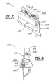
- Fig. 7 is a view explanatory of a fundamental construction of the vehicle door handle unit disclosed in JP 2005-330752 A
- Fig. 8 is a sectional view taken along line 8 - 8 of Fig. 7
- the disclosed vehicle door handle unit 200 includes a door-side member (door-side concave section) 202 fixed to a vehicle door (not shown), a support section 203 provided on an upper reverse surface portion of the door-side member 202, a handle section 205 pivotably attached to the support section 203 via a handle shaft 204, torsion springs (biasing members) 206 wound on the support section 203 and resiliently acting between the support section 203 and the handle section 205, and a push switch 209 supported by the door-side member 202 and having a depressing portion 208 exposed through an opening 207 of the handle section 205.
- a door-side member door-side concave section
- a support section 203 provided on an upper reverse surface portion of the door-side member 202
- the opening 207 is located close to one end of the handle section 205 as viewed in an axial direction of the support section 203.
- the push switch (detection section) 209 is exposed on the outer surface of the handle section 205, the support section 203 supporting the handle section 205 is provided on the inner side of the vehicle door (i.e., side facing the interior of the vehicle), the door handle unit 200 would require a great overall depth or thickness, and thus it is difficult to apply the vehicle door handle unit 200 to small-size vehicles etc, having a small layout space.
- the push switch 209 is located close to the one end of the handle section 205 as viewed in the axial direction of the support section 203, the door handle unit 200 would have a poor usability
- an object of the present invention to provide an improved vehicle door handle unit which can be suitably applied to small vehicles etc. of which the vehicle door can only have a limited thickness, and which has a good usability, i.e. is very easy to use.
- the present invention provides an improved vehicle door handle unit, which comprises: a handle shaft rotatably mounted on a vehicle door; a handle section pivotably mounted on the handle shaft; and a detection section for detecting locking/ unlocking operation of the vehicle door or opening/closing-related operation including opening/closing operation of the vehicle door.
- the handle shaft comprises first and second handle shaft members axially spaced apart from each other, and the detection section is provided between the first and second handle shaft members.
- the detection section it is possible to detect locking/ unlocking operation of the vehicle door or opening/closing-related operation including opening/closing operation of the vehicle door.
- the vehicle door can be automatically locked/unlocked, for example, by a vehicle driver or passenger with an IC card or the like touching the detection section, as a result of which it is possible to significantly enhance convenience of the vehicle driver or passenger.
- the vehicle door handle unit can be constructed in a compact size. Further, with the detection section provided between the spared-apart first and second handle shaft members, it is possible to avoid the handle shaft and detection section from interfering with each other in the outward-inward direction (i.e., width direction) of the vehicle, and thus, the vehicle door handle unit can be suitably applied to small-size vehicles of which the door can only have a limited thickness.
- the detection section is provided to be located in a recessed section formed in the outer peripheral edge of the handle section when the handle section is in its non-operating position.
- the detection section and handle section can present a sense of unity in appearance, so that the outer appearance of the vehicle door handle unit can be significantly enhanced
- the detection section is provided to project beyond an outer peripheral edge portion of the handle section adjacent to the handle shaft, and thus, it can be located as close to the handle shaft as possible. As a consequence, it is possible to secure a sufficiently great space for entry of a hand of the vehicle driver or passenger in operating the handle section.
- the detection section is provided to be located in an opening formed in the handle section when the handle section is in its non-operating position.
- the detection section and handle section can present an increased sense of unity in appearance, so that the outer appearance of the vehicle door handle unit can be even further enhanced.
- the detection section is provided in a middle region of the handle section as viewed in the axial direction of the handle shaft.
- the first and second handle shaft members can have substantially the same length, so that these two shaft members can be located symmetrically about the axial center of the handle section.
- the vehicle door handle unit can have an increased usability, i.e. can be used with an increased ease.
- Fig. 1 is a perspective view of a vehicle employing a vehicle door handle unit 30 according to a first embodiment of the present invention
- Fig. 2 is a perspective view of the vehicle door handle unit.
- the vehicle 10 includes a vehicle door 21 attached to a vehicle body 11 for opening and closing movement to allow a vehicle driver or passenger to get in and out of the vehicle.
- the vehicle door 21 includes a door body 22 openably/closeably attached to the vehicle body 11, a window frame 23 attached to an upper portion of the door body 22, a window glass 24 vertically movably mounted in the door body 22 and window frame 23, the vehicle door handle unit 30 pivotably attached to a door-side concave section of the door body 22, and a door mirror 27attached to the door body 22.
- the vehicle door handle unit 30 includes: a support section 31 formed in the door-side concave section 25 of the vehicle door 21; a handle shaft 32 attached to the support section 31; a handle section 33 pivotably mounted on the handle shaft 32; a detection section 34 mounted in the door-side concave section 25 and exposed through a recessed portion 62 between the handle section 33 and the vehicle door 21; and a biasing member 35 provided between the handle section 33 and the vehicle door 21 for normally urging the handle section 33 toward the vehicle door 21.
- the detection section 34 projects outwardly from an upper outer peripheral edge 33a of the handle section 33 adjacent to the handle shaft 32.
- Fig. 3 is an exploded perspective view of the vehicle door handle unit shown in Fig. 2
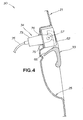
- Fig. 4 is a sectional view taken along the 4 - 4 line of Fig. 2
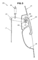
- Fig. 5 is a sectional view taken along the 5 - 5 line of Fig. 2 .
- the support section 31 includes first and second support sections 38 and 39 supporting first and second handle shaft members 56 and 57 of the handle shaft section 32.
- the first support section 38 includes inner and outer support portions 41 and 42 extending from the door-side section 25 of the vehicle door unit 21, and a first opening 43 formed between the support portions 41 and 42.
- the support portions 41 and 42 each have a hole 44 or 45 through which the first handle shaft member 56 extends.
- the second support section 39 includes inner and outer support portions 51 and 52 extending from the door-side section 25 of the vehicle door unit 21, and a second opening 53 formed between the support portions 51 and 52.
- the support portions 51 and 52 each have a hole 54 or 55 through which the second handle shaft member 57 extends.
- the handle shaft 32 is of a two-divided structure comprising the first handle shaft member 56 that is mounted to the first support section 38 to pivotably support the handle section 33 and the second handle shaft member 57 that is mounted to the second support section 39 to pivotably support the handle section 33.
- the first and second handle shaft members 56 and 57 are axially spaced apart from each other.
- the first and second handle shaft members 56 and 57 are fixed to the first and second support sections 38 and 39 by means of retaining rings 58 and 59.
- the handle section 33 includes: the recessed portion 62 formed in a middle region of the upper outer peripheral edge 33a, adjacent to the handle shaft 32, to allow the outer surface of the detection section 34 to be exposed; first and second fitting portions 64 and 65 provided to the left and right of the recessed portion 62 for fitting engagement with the first and second handle shaft members 56 and 57; and a guard wall 66 ( Fig. 4 ) provided beneath the first and second fitting portions 64 and 65 to prevent a human hand from undesirably reaching portions, other than the outer surface, the detection section 34 and first and second fitting portions 64 and 65.
- the vehicle driver or passenger can put its hand into the door handle unit with an increased ease.
- the first fitting portion 64 has a first bearing portion 68 having a substantially circular sectional shape opening over a circumferential region thereof so that it can be attached onto and pivotably supported on the first handle shaft member 56.
- the second fitting portion 65 has a second bearing portion 69 having a substantially circular sectional shape opening over a circumferential region thereof so that it can be attached onto and pivotably supported on the second handle shaft member 57, and a lever 72 engaging with a connection member 71 extending inward from one end of the second bearing portion 69 and connected with a biasing member 35 in the form of a coil spring and with a locking/unlocking mechanism (not shown) of the vehicle door 21.
- the biasing member 35 normally urges the handle section 33 toward the vehicle door 21.
- the lever 72 extends through the second opening 53 inwardly of the vehicle door 21.
- the detection section 34 includes a housing 73, a sensor 74 provided on the housing 73 for detecting locking/unlocking operation of the vehicle door or opening/closing-related operation including opening/closing operation of the vehicle door, and a harness 75 extending from the sensor 74.
- the detection section 34 further includes claws 76 formed on the housing 73, and it is engageable at the claws 76 in a locking hole 79 formed in a switch mounting portion 78.
- the handle shaft 32 is rotatably mounted on the vehicle door 21
- the handle section 33 is pivotably mounted on the handle shaft 32
- the detection section 34 is provided for detecting locking/unlocking operation of the vehicle door 21 or opening/ closing-related operation including opening/closing operation of the vehicle door 21.
- the detection section 34 it is possible to detect locking/unlocking operation of the vehicle door 21 or opening/closing-related operation including opening/closing operation of the vehicle door 21.
- the vehicle door 21 can be automatically locked/unlocked, for example, by the vehicle driver or passenger with an IC card or the like touching the detection section 34, as a result of which it is possible to significantly enhance convenience of the vehicle driver or passenger.
- the vehicle door handle unit 30 having the detection section 34 can be constructed compactly. Further, with the detection section 34 provided between the spared-apart first and second handle shaft members, it is possible to avoid the handle shaft 32 and detection section 34 from interfering with each other in the outward-inward direction (i.e., width direction) of the vehicle, and thus, the vehicle door handle unit 30 can be suitably applied to small-size vehicles of which the door 21 can only have a limited thickness.
- the detection section 34 is located in the upper recessed portion 62 formed in the upper outer peripheral edge of the handle section 33 while the handle section 33 is in its non-operating position, the detection section 34 and handle section 33 can present a sense of unity in appearance, so that the outer appearance of the vehicle door handle unit 30 can be significantly enhanced.
- the detection section 34 is provided so as to project beyond the upper outer peripheral edge 33a of the handle section 33 adjacent to the handle shaft 33, it can be located as close to the handle shaft 32 as possible. As a consequence, it is possible to secure a sufficiently great space for entry of a hand of the vehicle driver or passenger in operating the handle section 33.
- the first and second handle shaft members 56 and 57 can have substantially the same length, so that these two shaft members 56 and 57 can be located symmetrically about the axial center of the handle section 33. As a consequence, not only the pivoting operation of the handle section 33 can be performed stably, but also the vehicle door handle unit 30 can be used with an increased ease.
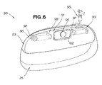
- Fig. 6 is a perspective view of a vehicle door handle unit 90 according to a second embodiment of the present invention.
- the vehicle door handle unit 90 includes: a support section 91 formed in the door-side concave section 25 of the vehicle door 21; a handle shaft 92 attached to the support section 91; a handle section 93 pivotably mounted on the handle shaft 92; a detection section 94 mounted in the door-side concave section 25 and exposed through an opening 102 formed in the handle section 93; and a biasing member 95 provided between the handle section 93 and the vehicle door 21 for normally urging the handle section 93 toward the vehicle door 21.
- the handle shaft 92 is of a two-divided structure comprising a first handle shaft member 96 and a second handle shaft member 97 axially spaced apart from each other.
- the support section 91 includes a first support portion 98 supporting the first handle shaft member 96, and a second support portion 99 supporting the second handle shaft member 97.
- the support section 91, handle shaft 92, handle section 93, detection section 94, biasing member 95 in the second embodiment are of generally the same constructions as the support section 31, handle shaft 32, handle section 33, detection section 34 and biasing member 35, except that the handle section 93 has the opening 102.
- the detection section 94 is located in the opening 102 formed in the handle section 93 when the handle section is not in its non-operating position, the detection section 94 and handle section 93 can present an increased sense of unity in appearance, so that the outer appearance of the vehicle door handle unit 90 can be even further enhanced.
- the handle section 33 or 93 in each of the first and second embodiments 30 and 90 of the present invention has been described above as normally urged toward the door 21 by the biasing member 35 or 95 in the form of a coil spring (see Figs. 2 and 6 ).
- the present invention is not so limited, and a torsion spring may be provided around each of the first and second handle shaft members 56 and 57, or 96 and 97 for normally urging the handle section 33 or 93 toward the door 21.
- the senor 74 may be replaced with a mechanical switch, such as a push switch.
- the vehicle door handle unit of the present invention is suited particularly for use in small-size vehicles, such as sedans and wagons.
- Vehicle door handle unit includes a handle shaft (32; 92) rotatably mounted on a vehicle door (21); a handle section (33; 93) pivotably mounted on the handle shaft; and a detection section (34; 94) for detecting locking/ unlocking operation of the vehicle door or opening/closing-related operation including opening/closing operation of the vehicle door.
- the handle shaft includes first and second handle shaft members (56, 57; 96, 97) axially spaced apart from each other, and the detection section is provided between the first and second handle shaft members.
- the vehicle door handle unit can be suitably applied to small vehicles etc. of which the vehicle door can only have a limited thickness, but also it can have a good usability.
Landscapes
- Lock And Its Accessories (AREA)
Abstract
Description
- The present invention relates vehicle door handle units including a detection section for detecting locking/unlocking operation of a vehicle door or opening/closing-related operation including opening/closing operation of the vehicle door.
- Vehicle door handle units have been known which are equipped with a detection section including a sensor or switch for locking/unlocking operation of a vehicle door. Namely, these vehicle door handle units can automatically perform processing for locking/unlocking the vehicle door or opening/ closing-related processing, including opening/closing of the vehicle door, in response to a vehicle driver or passenger, carrying an IC card or the like, touching the detection section. Japanese Patent Application Laid-Open Publication No.
2005-330752 JP 2005-330752 A -
Fig. 7 is a view explanatory of a fundamental construction of the vehicle door handle unit disclosed inJP 2005-330752 A Fig. 8 is a sectional view taken along line 8 - 8 ofFig. 7 . The disclosed vehicledoor handle unit 200 includes a door-side member (door-side concave section) 202 fixed to a vehicle door (not shown), asupport section 203 provided on an upper reverse surface portion of the door-side member 202, ahandle section 205 pivotably attached to thesupport section 203 via ahandle shaft 204, torsion springs (biasing members) 206 wound on thesupport section 203 and resiliently acting between thesupport section 203 and thehandle section 205, and apush switch 209 supported by the door-side member 202 and having a depressingportion 208 exposed through an opening 207 of thehandle section 205. The opening 207 is located close to one end of thehandle section 205 as viewed in an axial direction of thesupport section 203. However, in the disclosed vehicle door handle unit, where the push switch (detection section) 209 is exposed on the outer surface of thehandle section 205, thesupport section 203 supporting thehandle section 205 is provided on the inner side of the vehicle door (i.e., side facing the interior of the vehicle), thedoor handle unit 200 would require a great overall depth or thickness, and thus it is difficult to apply the vehicledoor handle unit 200 to small-size vehicles etc, having a small layout space. Further, because thepush switch 209 is located close to the one end of thehandle section 205 as viewed in the axial direction of thesupport section 203, thedoor handle unit 200 would have a poor usability - In view of the foregoing prior art problems, it is an object of the present invention to provide an improved vehicle door handle unit which can be suitably applied to small vehicles etc. of which the vehicle door can only have a limited thickness, and which has a good usability, i.e. is very easy to use.
- In order to accomplish the above-mentioned object, the present invention provides an improved vehicle door handle unit, which comprises: a handle shaft rotatably mounted on a vehicle door; a handle section pivotably mounted on the handle shaft; and a detection section for detecting locking/ unlocking operation of the vehicle door or opening/closing-related operation including opening/closing operation of the vehicle door. The handle shaft comprises first and second handle shaft members axially spaced apart from each other, and the detection section is provided between the first and second handle shaft members.
- With the detection section, it is possible to detect locking/ unlocking operation of the vehicle door or opening/closing-related operation including opening/closing operation of the vehicle door. In this way, the vehicle door can be automatically locked/unlocked, for example, by a vehicle driver or passenger with an IC card or the like touching the detection section, as a result of which it is possible to significantly enhance convenience of the vehicle driver or passenger.
- Further, with the detection section provided between the first and second handle shaft members of the handle shaft, the vehicle door handle unit can be constructed in a compact size. Further, with the detection section provided between the spared-apart first and second handle shaft members, it is possible to avoid the handle shaft and detection section from interfering with each other in the outward-inward direction (i.e., width direction) of the vehicle, and thus, the vehicle door handle unit can be suitably applied to small-size vehicles of which the door can only have a limited thickness.
- In an embodiment, the detection section is provided to be located in a recessed section formed in the outer peripheral edge of the handle section when the handle section is in its non-operating position. Thus, the detection section and handle section can present a sense of unity in appearance, so that the outer appearance of the vehicle door handle unit can be significantly enhanced
- In an embodiment, the detection section is provided to project beyond an outer peripheral edge portion of the handle section adjacent to the handle shaft, and thus, it can be located as close to the handle shaft as possible. As a consequence, it is possible to secure a sufficiently great space for entry of a hand of the vehicle driver or passenger in operating the handle section.
- In an embodiment, the detection section is provided to be located in an opening formed in the handle section when the handle section is in its non-operating position. Thus, the detection section and handle section can present an increased sense of unity in appearance, so that the outer appearance of the vehicle door handle unit can be even further enhanced.
- In an embodiment, the detection section is provided in a middle region of the handle section as viewed in the axial direction of the handle shaft. Thus, the first and second handle shaft members can have substantially the same length, so that these two shaft members can be located symmetrically about the axial center of the handle section. As a consequence, not only the pivoting operation of the handle section can be performed stably, but also the vehicle door handle unit can have an increased usability, i.e. can be used with an increased ease.
- The following will describe embodiments of the present invention, but it should be appreciated that the present invention is not limited to the described embodiments and various modifications of the invention are possible without departing from the basic principles. The scope of the present invention is therefore to be determined solely by the appended claims.
- Certain preferred embodiments of the present invention will be described in detail below, by way of example only, with reference to the accompanying drawings, in which:
-
Fig. 1 is a perspective view of a vehicle employing a vehicle door handle unit according to a first embodiment of the present invention; -
Fig. 2 is a perspective view showing the vehicle door handle unit ofFig. 1 ; -
Fig. 3 is an exploded perspective view of the vehicle door handle unit shown inFig. 2 ; -
Fig. 4 is a sectional view taken along line 4 - 4 ofFig. 2 ; -
Fig. 5 is a sectional view taken along line 5 - 5 ofFig. 2 ; -
Fig. 6 is a perspective view of a vehicle door handle unit according to a second embodiment of the present invention; -
Fig. 7 is a view explanatory of a fundamental construction of a conventionally-known vehicle door handle unit; and -
Fig. 8 is a sectional view taken along line 8 - 8 ofFig. 7 . -
Fig. 1 is a perspective view of a vehicle employing a vehicledoor handle unit 30 according to a first embodiment of the present invention, andFig. 2 is a perspective view of the vehicle door handle unit. Thevehicle 10 includes avehicle door 21 attached to a vehicle body 11 for opening and closing movement to allow a vehicle driver or passenger to get in and out of the vehicle. - The
vehicle door 21 includes adoor body 22 openably/closeably attached to the vehicle body 11, awindow frame 23 attached to an upper portion of thedoor body 22, awindow glass 24 vertically movably mounted in thedoor body 22 andwindow frame 23, the vehicledoor handle unit 30 pivotably attached to a door-side concave section of thedoor body 22, and a door mirror 27attached to thedoor body 22. - The vehicle
door handle unit 30 includes: asupport section 31 formed in the door-sideconcave section 25 of thevehicle door 21; ahandle shaft 32 attached to thesupport section 31; ahandle section 33 pivotably mounted on thehandle shaft 32; adetection section 34 mounted in the door-sideconcave section 25 and exposed through a recessedportion 62 between thehandle section 33 and thevehicle door 21; and abiasing member 35 provided between thehandle section 33 and thevehicle door 21 for normally urging thehandle section 33 toward thevehicle door 21. Thedetection section 34 projects outwardly from an upper outerperipheral edge 33a of thehandle section 33 adjacent to thehandle shaft 32. -
Fig. 3 is an exploded perspective view of the vehicle door handle unit shown inFig. 2 ,Fig. 4 is a sectional view taken along the 4 - 4 line ofFig. 2 , andFig. 5 is a sectional view taken along the 5 - 5 line ofFig. 2 . - The
support section 31 includes first andsecond support sections handle shaft members handle shaft section 32. - The
first support section 38 includes inner andouter support portions side section 25 of thevehicle door unit 21, and afirst opening 43 formed between thesupport portions support portions hole handle shaft member 56 extends. - Similarly, the
second support section 39 includes inner andouter support portions side section 25 of thevehicle door unit 21, and asecond opening 53 formed between thesupport portions support portions hole handle shaft member 57 extends. - The
handle shaft 32 is of a two-divided structure comprising the firsthandle shaft member 56 that is mounted to thefirst support section 38 to pivotably support thehandle section 33 and the secondhandle shaft member 57 that is mounted to thesecond support section 39 to pivotably support thehandle section 33. The first and secondhandle shaft members handle shaft members second support sections rings - The
handle section 33 includes: therecessed portion 62 formed in a middle region of the upper outerperipheral edge 33a, adjacent to thehandle shaft 32, to allow the outer surface of thedetection section 34 to be exposed; first andsecond fitting portions portion 62 for fitting engagement with the first and secondhandle shaft members Fig. 4 ) provided beneath the first and secondfitting portions detection section 34 and first and secondfitting portions - Namely, with the
guard wall 66 formed on thehandle section 33, the vehicle driver or passenger can put its hand into the door handle unit with an increased ease. - The
first fitting portion 64 has a first bearingportion 68 having a substantially circular sectional shape opening over a circumferential region thereof so that it can be attached onto and pivotably supported on the firsthandle shaft member 56. - The
second fitting portion 65 has a second bearingportion 69 having a substantially circular sectional shape opening over a circumferential region thereof so that it can be attached onto and pivotably supported on the secondhandle shaft member 57, and alever 72 engaging with aconnection member 71 extending inward from one end of the second bearingportion 69 and connected with abiasing member 35 in the form of a coil spring and with a locking/unlocking mechanism (not shown) of thevehicle door 21. Thebiasing member 35 normally urges thehandle section 33 toward thevehicle door 21. Thelever 72 extends through the second opening 53 inwardly of thevehicle door 21. - The
detection section 34 includes ahousing 73, asensor 74 provided on thehousing 73 for detecting locking/unlocking operation of the vehicle door or opening/closing-related operation including opening/closing operation of the vehicle door, and aharness 75 extending from thesensor 74. - As shown in
Fig. 4 , thedetection section 34 further includesclaws 76 formed on thehousing 73, and it is engageable at theclaws 76 in alocking hole 79 formed in aswitch mounting portion 78. - Namely, in the vehicle
door handle unit 30, thehandle shaft 32 is rotatably mounted on thevehicle door 21, thehandle section 33 is pivotably mounted on thehandle shaft 32, and thedetection section 34 is provided for detecting locking/unlocking operation of thevehicle door 21 or opening/ closing-related operation including opening/closing operation of thevehicle door 21. Thus, with thedetection section 34, it is possible to detect locking/unlocking operation of thevehicle door 21 or opening/closing-related operation including opening/closing operation of thevehicle door 21. In this way, thevehicle door 21 can be automatically locked/unlocked, for example, by the vehicle driver or passenger with an IC card or the like touching thedetection section 34, as a result of which it is possible to significantly enhance convenience of the vehicle driver or passenger. - Further, because the
detection section 34 is provided between the first and secondhandle shaft members handle shaft 32, the vehicledoor handle unit 30 having thedetection section 34 can be constructed compactly. Further, with thedetection section 34 provided between the spared-apart first and second handle shaft members, it is possible to avoid thehandle shaft 32 anddetection section 34 from interfering with each other in the outward-inward direction (i.e., width direction) of the vehicle, and thus, the vehicledoor handle unit 30 can be suitably applied to small-size vehicles of which thedoor 21 can only have a limited thickness. - Further, because the
detection section 34 is located in the upperrecessed portion 62 formed in the upper outer peripheral edge of thehandle section 33 while thehandle section 33 is in its non-operating position, thedetection section 34 andhandle section 33 can present a sense of unity in appearance, so that the outer appearance of the vehicledoor handle unit 30 can be significantly enhanced. - Furthermore, because the
detection section 34 is provided so as to project beyond the upper outerperipheral edge 33a of thehandle section 33 adjacent to thehandle shaft 33, it can be located as close to thehandle shaft 32 as possible. As a consequence, it is possible to secure a sufficiently great space for entry of a hand of the vehicle driver or passenger in operating thehandle section 33. - Furthermore, because the
detection section 34 is provided in a middle region of thehandle section 33 as viewed in the axial direction of thehandle shaft 32, the first and secondhandle shaft members shaft members handle section 33. As a consequence, not only the pivoting operation of thehandle section 33 can be performed stably, but also the vehicledoor handle unit 30 can be used with an increased ease. -
Fig. 6 is a perspective view of a vehicledoor handle unit 90 according to a second embodiment of the present invention. The vehicledoor handle unit 90 includes: asupport section 91 formed in the door-sideconcave section 25 of thevehicle door 21; ahandle shaft 92 attached to thesupport section 91; ahandle section 93 pivotably mounted on thehandle shaft 92; adetection section 94 mounted in the door-sideconcave section 25 and exposed through anopening 102 formed in thehandle section 93; and a biasingmember 95 provided between thehandle section 93 and thevehicle door 21 for normally urging thehandle section 93 toward thevehicle door 21. - The
handle shaft 92 is of a two-divided structure comprising a firsthandle shaft member 96 and a secondhandle shaft member 97 axially spaced apart from each other. Thesupport section 91 includes afirst support portion 98 supporting the firsthandle shaft member 96, and asecond support portion 99 supporting the secondhandle shaft member 97. - The
support section 91, handleshaft 92,handle section 93,detection section 94, biasingmember 95 in the second embodiment are of generally the same constructions as thesupport section 31, handleshaft 32,handle section 33,detection section 34 and biasingmember 35, except that thehandle section 93 has theopening 102. - In the second embodiment, where the
detection section 94 is located in theopening 102 formed in thehandle section 93 when the handle section is not in its non-operating position, thedetection section 94 and handlesection 93 can present an increased sense of unity in appearance, so that the outer appearance of the vehicledoor handle unit 90 can be even further enhanced. - The
handle section second embodiments door 21 by the biasingmember Figs. 2 and6 ). However, the present invention is not so limited, and a torsion spring may be provided around each of the first and secondhandle shaft members handle section door 21. - Further, whereas each of the first and
second embodiments sensor 74 in thedetection section 34 or 94 (see, for example,Fig. 3 ), thesensor 74 may be replaced with a mechanical switch, such as a push switch. - The vehicle door handle unit of the present invention is suited particularly for use in small-size vehicles, such as sedans and wagons.
- Vehicle door handle unit includes a handle shaft (32; 92) rotatably mounted on a vehicle door (21); a handle section (33; 93) pivotably mounted on the handle shaft; and a detection section (34; 94) for detecting locking/ unlocking operation of the vehicle door or opening/closing-related operation including opening/closing operation of the vehicle door. The handle shaft includes first and second handle shaft members (56, 57; 96, 97) axially spaced apart from each other, and the detection section is provided between the first and second handle shaft members. Not only the vehicle door handle unit can be suitably applied to small vehicles etc. of which the vehicle door can only have a limited thickness, but also it can have a good usability.
Claims (5)
- A vehicle door handle unit comprising:a handle shaft (32; 92) rotatably mounted on a vehicle door (21);a handle section (33; 93) pivotably mounted on said handle shaft; anda detection section (34; 94) for detecting locking/unlocking operation of the vehicle door or opening/closing-related operation including opening/ closing operation of the vehicle door,wherein said handle shaft comprises first and second handle shaft members (56, 57; 96, 97) axially spaced apart from each other, and said detection section is provided between said first and second handle shaft members.
- The vehicle door handle unit of claim 1, wherein said detection section (34; 94) is provided to be located in a recessed section (62) formed in an outer peripheral edge of said handle section when said handle section is in a non-operating position.
- The vehicle door handle unit of claim 2, wherein said detection section (34; 94) is provided to project beyond an outer peripheral edge portion (33a) of said handle section adjacent to said handle shaft.
- The vehicle door handle unit of claim 1, wherein said detection section (34; 94) is provided to be located in an opening (102) formed in said handle section when said handle section is in a non-operating position.
- The vehicle door handle unit of claim 1, wherein said detection section (34; 94) is provided in a middle region of said handle section as viewed in an axial direction of said handle shaft.
Applications Claiming Priority (1)
| Application Number | Priority Date | Filing Date | Title |
|---|---|---|---|
| JP2007105741A JP2008261175A (en) | 2007-04-13 | 2007-04-13 | Vehicle door handle |
Publications (2)
| Publication Number | Publication Date |
|---|---|
| EP1980691A1 true EP1980691A1 (en) | 2008-10-15 |
| EP1980691B1 EP1980691B1 (en) | 2011-10-26 |
Family
ID=39628952
Family Applications (1)
| Application Number | Title | Priority Date | Filing Date |
|---|---|---|---|
| EP20080006811 Expired - Fee Related EP1980691B1 (en) | 2007-04-13 | 2008-04-03 | Vehicle door handle unit |
Country Status (4)
| Country | Link |
|---|---|
| US (1) | US8136853B2 (en) |
| EP (1) | EP1980691B1 (en) |
| JP (1) | JP2008261175A (en) |
| CN (1) | CN101285353B (en) |
Cited By (1)
| Publication number | Priority date | Publication date | Assignee | Title |
|---|---|---|---|---|
| FR2942637A1 (en) * | 2009-03-02 | 2010-09-03 | Valeo Securite Habitacle | HANDLE OF AN OPENING OF A MOTOR VEHICLE |
Families Citing this family (12)
| Publication number | Priority date | Publication date | Assignee | Title |
|---|---|---|---|---|
| JP4934074B2 (en) * | 2007-03-07 | 2012-05-16 | 株式会社アルファ | Switch fixing structure |
| JP5220558B2 (en) | 2008-11-04 | 2013-06-26 | 株式会社アルファ | Door handle device |
| GB2477085B (en) * | 2010-01-15 | 2014-08-20 | Jaguar Land Rover Ltd | Retractable handle for a door or the like |
| USD874243S1 (en) | 2011-06-21 | 2020-02-04 | Jaguar Land Rover Limited | Vehicle door handle |
| GB2492319A (en) | 2011-06-21 | 2013-01-02 | Jaguar Cars | Retractable handle |
| JP5638014B2 (en) * | 2012-01-24 | 2014-12-10 | 株式会社ホンダロック | Vehicle door opening / closing operation device |
| US9957737B2 (en) | 2012-06-29 | 2018-05-01 | Ford Global Technologies, Llc | Flush-mounted door handle for vehicles |
| US8701353B2 (en) | 2012-06-29 | 2014-04-22 | Ford Global Technologies, Llc | Deployable door handle for vehicles |
| JP6907797B2 (en) * | 2017-08-09 | 2021-07-21 | トヨタ自動車株式会社 | Vehicle door open / close control device |
| JP7073892B2 (en) * | 2018-05-08 | 2022-05-24 | トヨタ自動車株式会社 | Vehicle door latch release device |
| US12546150B2 (en) * | 2021-01-07 | 2026-02-10 | Ford Global Technologies, Llc | Door assembly for motor vehicle |
| CN116411746B (en) * | 2021-12-30 | 2024-10-29 | 比亚迪股份有限公司 | Vehicle door control method and device, vehicle and computer storage medium |
Citations (7)
| Publication number | Priority date | Publication date | Assignee | Title |
|---|---|---|---|---|
| JPS6055187A (en) | 1983-09-06 | 1985-03-30 | アイシン精機株式会社 | Automatic door lock controller |
| JPS6278376A (en) | 1985-09-28 | 1987-04-10 | アイシン精機株式会社 | Handle switch for car |
| JPS62248768A (en) | 1986-04-22 | 1987-10-29 | 富士重工業株式会社 | Keyless entry apparatus of car |
| FR2865708A1 (en) * | 2004-01-29 | 2005-08-05 | Neyr Plastiques Holding | Lock opening control module for vehicle casement e.g. tailgate, has layer covering support and vane of control unit and forming watertight joint on periphery of support, where layer is made of elastic material |
| JP2005330752A (en) | 2004-05-21 | 2005-12-02 | Matsushita Electric Ind Co Ltd | Door handle unit |
| JP3783729B1 (en) * | 2005-11-01 | 2006-06-07 | 松下電器産業株式会社 | Operation detection device or door opening and closing device |
| JP2007231711A (en) * | 2006-01-31 | 2007-09-13 | Matsushita Electric Ind Co Ltd | Contact detection device, door handle device including the same, and smart entry system |
Family Cites Families (19)
| Publication number | Priority date | Publication date | Assignee | Title |
|---|---|---|---|---|
| US2460607A (en) * | 1946-05-02 | 1949-02-01 | Studebaker Corp | Push-button means |
| US4232892A (en) * | 1977-03-31 | 1980-11-11 | Aisin Seiki Kabushiki Kaisha | Outside door handle assembly for vehicles |
| JPS57174661A (en) | 1981-04-20 | 1982-10-27 | Tokyo Shibaura Electric Co | Refrigeration cycle |
| JPS5931870Y2 (en) * | 1981-04-30 | 1984-09-07 | 日産自動車株式会社 | Mounting structure of push-button electronic lock switch for automobiles |
| JPS60203786A (en) * | 1984-03-28 | 1985-10-15 | 日産自動車株式会社 | Outside handle apparatus for electronic lock for car |
| US4634161A (en) * | 1984-11-29 | 1987-01-06 | Kokusan Kinzoku Kogyo Kabushiki Kaisha | Automotive outside door handle unit |
| US4653143A (en) * | 1986-03-03 | 1987-03-31 | General Motors Corporation | Vehicle door handle assembly |
| JPH0639006Y2 (en) * | 1986-09-30 | 1994-10-12 | アイシン精機株式会社 | Inside handle device for vehicle |
| JPH0629381Y2 (en) * | 1988-03-24 | 1994-08-10 | 株式会社大井製作所 | Inside handle device for vehicle |
| JP3319878B2 (en) * | 1994-06-15 | 2002-09-03 | サカエ理研工業株式会社 | Door handle device |
| KR100204959B1 (en) * | 1994-12-30 | 1999-06-15 | 전성원 | Car door opener |
| US5794994A (en) * | 1995-08-09 | 1998-08-18 | Ohi Seisakusho Co., Ltd. | Inside door handle unit for automotive vehicle |
| DE19629197C2 (en) * | 1996-07-19 | 1999-05-06 | Schmidt Gmbh R | Handle in a motor vehicle |
| JPH1122256A (en) * | 1997-07-03 | 1999-01-26 | Mitsubishi Motors Corp | Door outside handle |
| CN2423350Y (en) * | 2000-01-03 | 2001-03-14 | 宁海县春雷模具制造有限公司 | turnover door handle special for santana |
| JP2004052506A (en) * | 2002-07-24 | 2004-02-19 | Mitsubishi Automob Eng Co Ltd | Vehicle door handle device |
| US6976717B2 (en) * | 2003-02-06 | 2005-12-20 | Delphi Technologies, Inc. | Vehicle door handle assembly |
| JP4238167B2 (en) * | 2004-03-30 | 2009-03-11 | 三井金属鉱業株式会社 | Inside handle device |
| JP4934074B2 (en) * | 2007-03-07 | 2012-05-16 | 株式会社アルファ | Switch fixing structure |
-
2007
- 2007-04-13 JP JP2007105741A patent/JP2008261175A/en active Pending
-
2008
- 2008-04-03 EP EP20080006811 patent/EP1980691B1/en not_active Expired - Fee Related
- 2008-04-08 US US12/099,324 patent/US8136853B2/en not_active Expired - Fee Related
- 2008-04-10 CN CN200810092162.7A patent/CN101285353B/en not_active Expired - Fee Related
Patent Citations (8)
| Publication number | Priority date | Publication date | Assignee | Title |
|---|---|---|---|---|
| JPS6055187A (en) | 1983-09-06 | 1985-03-30 | アイシン精機株式会社 | Automatic door lock controller |
| JPS6278376A (en) | 1985-09-28 | 1987-04-10 | アイシン精機株式会社 | Handle switch for car |
| JPS62248768A (en) | 1986-04-22 | 1987-10-29 | 富士重工業株式会社 | Keyless entry apparatus of car |
| FR2865708A1 (en) * | 2004-01-29 | 2005-08-05 | Neyr Plastiques Holding | Lock opening control module for vehicle casement e.g. tailgate, has layer covering support and vane of control unit and forming watertight joint on periphery of support, where layer is made of elastic material |
| JP2005330752A (en) | 2004-05-21 | 2005-12-02 | Matsushita Electric Ind Co Ltd | Door handle unit |
| JP3783729B1 (en) * | 2005-11-01 | 2006-06-07 | 松下電器産業株式会社 | Operation detection device or door opening and closing device |
| JP2007126819A (en) | 2005-11-01 | 2007-05-24 | Matsushita Electric Ind Co Ltd | Operation detection device or door opening and closing device |
| JP2007231711A (en) * | 2006-01-31 | 2007-09-13 | Matsushita Electric Ind Co Ltd | Contact detection device, door handle device including the same, and smart entry system |
Cited By (2)
| Publication number | Priority date | Publication date | Assignee | Title |
|---|---|---|---|---|
| FR2942637A1 (en) * | 2009-03-02 | 2010-09-03 | Valeo Securite Habitacle | HANDLE OF AN OPENING OF A MOTOR VEHICLE |
| WO2010100072A1 (en) * | 2009-03-02 | 2010-09-10 | Valeo Securite Habitacle | Handle for a door leaf of a motor vehicle |
Also Published As
| Publication number | Publication date |
|---|---|
| CN101285353B (en) | 2014-04-09 |
| US20080250607A1 (en) | 2008-10-16 |
| US8136853B2 (en) | 2012-03-20 |
| JP2008261175A (en) | 2008-10-30 |
| EP1980691B1 (en) | 2011-10-26 |
| CN101285353A (en) | 2008-10-15 |
Similar Documents
| Publication | Publication Date | Title |
|---|---|---|
| EP1980691A1 (en) | Vehicle door handle unit | |
| US10267072B2 (en) | Door handle apparatus for vehicle | |
| US20090236863A1 (en) | Electric door latch apparatus | |
| JP4648167B2 (en) | Glove box equipment | |
| US8256065B2 (en) | Hinge mechanism for display device | |
| FR3072705A1 (en) | EXTERNAL DOOR HANDLE ARRANGEMENT FOR A MOTOR VEHICLE | |
| JP2002295093A (en) | Vehicle Out-Handle Device | |
| JP4238167B2 (en) | Inside handle device | |
| WO2020031564A1 (en) | External handle device for vehicle doors | |
| US20100171328A1 (en) | Device for actuating the closure of a movable part | |
| JP4645324B2 (en) | Vehicle door | |
| JP5361601B2 (en) | Hinge mechanism and monitor device for ceiling suspension | |
| JP5204636B2 (en) | Door handle structure for vehicle | |
| JP5135285B2 (en) | Outdoor handle device for vehicle door | |
| JP4815382B2 (en) | Glove box equipment | |
| JP4543722B2 (en) | Vehicle door handle | |
| JP6764130B2 (en) | Vehicle steering wheel device | |
| JP7349973B2 (en) | Door operation assist device | |
| KR100821007B1 (en) | Inside door handle assembly of car | |
| JP4834860B2 (en) | Lock knob device for automobile | |
| JP5076649B2 (en) | Slide door prevention structure | |
| JP3246126B2 (en) | Outside handle structure for automobiles | |
| JP2004330936A (en) | Sliding door slide guide structure | |
| JP4290189B2 (en) | Interior equipment for vehicles | |
| JP2002070368A (en) | Door opening and closing device |
Legal Events
| Date | Code | Title | Description |
|---|---|---|---|
| PUAI | Public reference made under article 153(3) epc to a published international application that has entered the european phase |
Free format text: ORIGINAL CODE: 0009012 |
|
| 17P | Request for examination filed |
Effective date: 20080403 |
|
| AK | Designated contracting states |
Kind code of ref document: A1 Designated state(s): AT BE BG CH CY CZ DE DK EE ES FI FR GB GR HR HU IE IS IT LI LT LU LV MC MT NL NO PL PT RO SE SI SK TR |
|
| AX | Request for extension of the european patent |
Extension state: AL BA MK RS |
|
| 17Q | First examination report despatched |
Effective date: 20090313 |
|
| AKX | Designation fees paid |
Designated state(s): DE GB |
|
| GRAP | Despatch of communication of intention to grant a patent |
Free format text: ORIGINAL CODE: EPIDOSNIGR1 |
|
| RAP1 | Party data changed (applicant data changed or rights of an application transferred) |
Owner name: HONDA MOTOR CO., LTD. |
|
| GRAS | Grant fee paid |
Free format text: ORIGINAL CODE: EPIDOSNIGR3 |
|
| GRAA | (expected) grant |
Free format text: ORIGINAL CODE: 0009210 |
|
| AK | Designated contracting states |
Kind code of ref document: B1 Designated state(s): DE GB |
|
| REG | Reference to a national code |
Ref country code: GB Ref legal event code: FG4D |
|
| REG | Reference to a national code |
Ref country code: DE Ref legal event code: R096 Ref document number: 602008010705 Country of ref document: DE Effective date: 20120105 |
|
| PGFP | Annual fee paid to national office [announced via postgrant information from national office to epo] |
Ref country code: GB Payment date: 20120328 Year of fee payment: 5 |
|
| PGFP | Annual fee paid to national office [announced via postgrant information from national office to epo] |
Ref country code: DE Payment date: 20120419 Year of fee payment: 5 |
|
| PLBE | No opposition filed within time limit |
Free format text: ORIGINAL CODE: 0009261 |
|
| STAA | Information on the status of an ep patent application or granted ep patent |
Free format text: STATUS: NO OPPOSITION FILED WITHIN TIME LIMIT |
|
| 26N | No opposition filed |
Effective date: 20120727 |
|
| REG | Reference to a national code |
Ref country code: DE Ref legal event code: R097 Ref document number: 602008010705 Country of ref document: DE Effective date: 20120727 |
|
| GBPC | Gb: european patent ceased through non-payment of renewal fee |
Effective date: 20130403 |
|
| PG25 | Lapsed in a contracting state [announced via postgrant information from national office to epo] |
Ref country code: GB Free format text: LAPSE BECAUSE OF NON-PAYMENT OF DUE FEES Effective date: 20130403 Ref country code: DE Free format text: LAPSE BECAUSE OF NON-PAYMENT OF DUE FEES Effective date: 20131101 |
|
| REG | Reference to a national code |
Ref country code: DE Ref legal event code: R119 Ref document number: 602008010705 Country of ref document: DE Effective date: 20131101 |