EP1980430A2 - Air conditioning system for automotive vehicles - Google Patents
Air conditioning system for automotive vehicles Download PDFInfo
- Publication number
- EP1980430A2 EP1980430A2 EP08007053A EP08007053A EP1980430A2 EP 1980430 A2 EP1980430 A2 EP 1980430A2 EP 08007053 A EP08007053 A EP 08007053A EP 08007053 A EP08007053 A EP 08007053A EP 1980430 A2 EP1980430 A2 EP 1980430A2
- Authority
- EP
- European Patent Office
- Prior art keywords
- discharge electrodes
- air conditioning
- moisture
- electric short
- conditioning system
- Prior art date
- Legal status (The legal status is an assumption and is not a legal conclusion. Google has not performed a legal analysis and makes no representation as to the accuracy of the status listed.)
- Granted
Links
Images










Classifications
-
- B—PERFORMING OPERATIONS; TRANSPORTING
- B60—VEHICLES IN GENERAL
- B60H—ARRANGEMENTS OF HEATING, COOLING, VENTILATING OR OTHER AIR-TREATING DEVICES SPECIALLY ADAPTED FOR PASSENGER OR GOODS SPACES OF VEHICLES
- B60H3/00—Other air-treating devices
- B60H3/0071—Electrically conditioning the air, e.g. by ionizing
-
- B—PERFORMING OPERATIONS; TRANSPORTING
- B60—VEHICLES IN GENERAL
- B60H—ARRANGEMENTS OF HEATING, COOLING, VENTILATING OR OTHER AIR-TREATING DEVICES SPECIALLY ADAPTED FOR PASSENGER OR GOODS SPACES OF VEHICLES
- B60H1/00—Heating, cooling or ventilating devices
- B60H1/32—Cooling devices
- B60H1/3233—Cooling devices characterised by condensed liquid drainage means
Definitions
- the present invention relates to an air conditioning system for automotive vehicles and, more particularly, to an air conditioning system for automotive vehicles capable of avoiding electric short between first and second discharge electrodes, which would be caused by moisture, and consequently preventing generation of a spark between the first and second discharge electrodes and an otherwise generated discharge noise.
- a conventional air conditioning system includes an air conditioning case 10 in which a blower 20 is installed.
- the blower 20 includes a blower fan 22 and a blower motor 24 for driving the blower fan 22.
- the blower 20 serves to inhale an external air or an internal air through an external air inlet port 12 or an internal air inlet port 14 of the air conditioning case 10 and then to feed the inhaled air to an internal passageway 16 of the air conditioning case 10.
- the air conditioning system further includes an evaporator 30 arranged inside the internal passageway 16 of the air conditioning case 10.
- the evaporator 30 includes a coolant tube (not shown) through which coolant can flow.
- the evaporator 30 serves to cool the air passing through the internal passageway 16 and also to introduce the cooled air into a vehicle room, thereby keeping the vehicle room at a pleasant temperature.
- the air conditioning system further includes an ionizer 40 for emitting positive ions and negative ions toward the air flowing through the internal passageway 16.
- the ionizer 40 is installed on the upstream side of the evaporator 30 and includes a main body 42 attached to a side wall of the air conditioning case 10, first and second protection pipes 44 and 45 extending from the main body 42 toward the internal passageway 16 in a spaced-apart relationship with each other, and first and second discharge electrodes 46 and 48 extending through the first and second protection pipes 44 and 45 and protruding into the internal passageway 16.
- the first and second protection pipes 44 and 45 are arranged one above the other in such a manner that they penetrate a through-hole 17 formed in the air conditioning case 10 and extend inwardly from a side wall 16a of the internal passageway 16.
- the first and second discharge electrodes 46 and 48 extend through the first and second protection pipes 44 and 45 and protrude into the internal passageway 16 at their tip ends.
- the first and second discharge electrodes 46 and 48 are designed to generate negative ions and positive ions by irradiating high voltage pulses into the air flowing through the internal passageway 16.
- the negative ions and positive ions generated in the ionizer 40 are introduced into the evaporator 30 to sterilize bacteria and mold living in the evaporator 30 and also to deodorize the air supplied into the vehicle room, thereby enhancing the degree of cleanliness of the air introduced into the vehicle room and creating a comfortable vehicle room environment.
- moisture is condensed in and around the first and second discharge electrodes 46 and 48 of the ionizer 40 if the air introduced into the internal passageway 16 has high humidity.
- the condensed moisture is infiltrated into the first and second discharge electrodes 46 and 48, thus forming a water film which conducts an electric current between the first and second discharge electrodes 46 and 48.
- the electrical short through the water film causes a spark between the first and second discharge electrodes 46 and 48, consequently generating a discharge noise.
- an object of the present invention to provide an air conditioning system for automotive vehicles capable of avoiding electric short between first and second discharge electrodes, which would otherwise be caused by ambient moisture.
- Another object of the present invention is to provide an air conditioning system for automotive vehicles capable of preventing generation of a spark between first and second discharge electrodes and an otherwise generated discharge noise.
- the present invention provides an air conditioning system for automotive vehicles, comprising: an air conditioning case having an internal passageway; an ionizer for emitting positive ions and negative ions into the internal passageway of the air conditioning case, the ionizer including a main body and first and second discharge electrodes extending from the main body into the internal passageway in a spaced-apart relationship with each other; and an electric short preventing means for preventing moisture condensed in and around the first and second discharge electrodes from causing electric short between the first and second discharge electrodes.
- the electric short preventing means may comprise a water drainage rib for draining the moisture condensed in and around the first and second discharge electrodes to prevent the electric short between the first and second discharge electrodes.
- the water drainage rib is adapted to drain the moisture condensed in and around a lower one of the first and second discharge electrodes and is joined to a side wall of the internal passageway so that the condensed moisture can be drained toward the side wall.
- a structure that prevents formation of a water film between the first and second discharge electrodes. This prevents electric short between the first and second discharge electrodes, which would otherwise generate a spark between the first and second discharge electrodes and a discharge noise. As a consequence, it becomes possible to greatly improve the driving comfortableness.
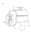
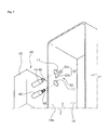
- Fig. 3 is a bottom perspective view showing a characterizing part of an air conditioning system for automotive vehicles in accordance with the present invention.
- Fig. 4 is a section view taken along line IV-IV in Fig. 3 .
- the air conditioning system includes an air conditioning case 10 in which a blower 20 is installed.
- the blower 20 inhales an external air or an internal air through an external air inlet port 12 or an internal air inlet port 14 formed in the air conditioning case 10 and then feed the inhaled air to an internal passageway 16 of the air conditioning case 10.
- the air conditioning system includes an evaporator 30 installed within the internal passageway 16 of the air conditioning case 10.
- the evaporator 30 serves to cool the air passing through the internal passageway 16.
- the cooled air is introduced into a vehicle room, thereby keeping the vehicle room at a pleasant temperature.
- the air conditioning system further includes an ionizer 40 for emitting positive ions and negative ions toward the air flowing through the internal passageway 16.
- the ionizer 40 is installed on the upstream side of the evaporator 30 and includes a main body 42 attached to an external surface of the air conditioning case 10, first and second protection pipes 44 and 45 extending from the main body 42 toward the internal passageway 16 in a spaced-apart relationship with each other, and first and second discharge electrodes 46 and 48 extending through the first and second protection pipes 44 and 45 and protruding into the internal passageway 16.
- the first and second protection pipes 44 and 45 are arranged one above the other in such a manner that they penetrate a through-hole 17 formed in the air conditioning case 10 and extend inwardly from a side wall 16a of the internal passageway 16.
- the first and second discharge electrodes 46 and 48 extend through the first and second protection pipes 44 and 45 and protrude into the internal passageway 16 at their tip ends.
- the first and second discharge electrodes 46 and 48 are designed to generate negative ions and positive ions by irradiating high voltage pulses into the air flowing through the internal passageway 16.
- the air conditioning system of the present invention includes an electric short preventing means 50 for preventing electric short between the first and second discharge electrodes 46 and 48, which would otherwise be caused by moisture.
- the electric short preventing means 50 includes a water drainage rib 52 designed to drain the moisture existing between the first and second discharge electrodes 46 and 48.
- the water drainage rib 52 is comprised of a connection portion 52a connected to a bottom surface 45a of the second protection pipe 45, i.e., the lower one of the first and second protection pipes 44 and 45, and a water drainage portion 52b extending downwardly from the connection portion 52a along a gravitational direction.
- the water drainage portion 52b has a bottom slanting surface inclined toward the side wall 16a of the internal passageway 16. Therefore, the bottom slanting surface is joined to the side wall 16a of the internal passageway 16.
- a reception groove 16c for receiving the water drainage rib 52 of the second protection pipe 45 is formed in the side wall 16a of the internal passageway 16.
- the water drainage rib 52 serves to rapidly drain the condensed moisture in a downward direction. At this time, the condensed moisture is guided toward and drained along the side wall 16a of the internal passageway 16.
- the water drainage rib 52 may be integrally formed with a bottom surface 44a of the first protection pipe 44 as shown in Fig. 5 .
- the water drainage rib 52 provided in the bottom surface 44a of the first protection pipe 44 serves to downwardly drain the moisture condensed in and around the first protection pipe 44.
- the moisture is prevented from infiltrating into the first discharge electrode 46 arranged within the first protection pipe 44.
- This prevents formation of a water film between the first and second discharge electrodes 46 and 48. Accordingly, it is possible to prevent electric short between the first and second discharge electrodes 46 and 48, which would otherwise generate a spark between the first and second discharge electrodes 46 and 48 and a discharge noise.
- the water drainage rib 52 be formed on the bottom surface 45a of the second protection pipe 45 rather than the first protection pipe 44. The reason is that, if the water drainage rib 52 is formed in the first protection pipe 44, the moisture drained from the water drainage rib 52 may flow toward the second protection pipe 45 in a large quantity.
- two water drainage ribs 52 may be formed on the bottom surfaces 44a and 45a of the first and second protection pipes 44 and 45 as illustrated in Fig. 6 . In this case, it is possible to drain the moisture condensed in and around the first and second protection pipes 44 and 45.
- Figs. 7 and 8 are bottom perspective and section views illustrating a modified example of the water drainage rib 52.
- the water drainage rib 52 of this modified example is integrally formed with the side wall 16a of the internal passageway 16.
- the water drainage rib 52 of this modified example is comprised of a connection portion 52a that makes contact with the bottom surface 45a of the second protection pipe 45 and a water drainage portion 52b extending downwardly from the connection portion 52a along a gravitational direction.
- the water drainage rib 52 of this modified example serves to downwardly guide and drain the moisture flowing down from the bottom surface 45a of the second protection pipe 45. In particular, the moisture is guided along the water drainage portion 52b and drained toward the side wall 16a of the internal passageway 16.
- the moisture condensed in and around the second protection pipe 45 is prevented from flowing toward the tip end of the second protection pipe 45 and infiltrating into the second discharge electrode 48. This prevents formation of a water film between the first and second discharge electrodes 46 and 48.
- the water drainage rib 52 of this modified example may be arranged below the bottom surface 44a of the first protection pipe 44 as illustrated in Fig. 9 .
- the water drainage rib 52 serves to downwardly drain the moisture condensed in and around the first protection pipe 44.
- the moisture condensed in and around the first protection pipe 44 is prevented from infiltrating into the first discharge electrode 46 arranged in the first protection pipe 44. This prevents formation of a water film between the first and second discharge electrodes 46 and 48.
- two water drainage ribs 52 may be arranged below the bottom surfaces 44a and 45a of the first and second protection pipes 44 and 45 as illustrated in Fig. 10 . In this case, it is possible to drain the whole moisture condensed in and around the first and second protection pipes 44 and 45.
- the electric short preventing means 50 of the second embodiment is useful in case where the ionizer 40 is installed in a ceiling wall 16b of the internal passageway 16.
- the electric short preventing means 50 includes an isolation baffle 60 arranged between the first and second discharge electrodes 46 and 48.
- the isolation baffle 60 is integrally formed with the bottom surface of the main body 42 of the ionizer 40.
- the isolation baffle 60 is inserted through a through-hole 17 of the air conditioning case 10 together with the first and second discharge electrodes 46 and 48 so that it can protrude into the internal passageway 16.
- the isolation baffle 60 is formed in parallel with an air flow direction so as not to hinder the flow of air in the internal passageway 16.
- the isolation baffle 60 extends in a gravitational direction to downwardly guide and drain the moisture which would otherwise flow between the first and second discharge electrodes 46 and 48.
- the isolation baffle 60 is designed to isolate the first and second discharge electrodes 46 and 48 from each other, it is possible to restrain the condensed moisture from flowing between the first and second discharge electrodes 46 and 48.
- the isolation baffle 60 is designed to downwardly drain the condensed moisture existing between the first and second discharge electrodes 46 and 48, it is possible to effectively prevent formation of a water film between the first and second discharge electrodes 46 and 48, which would otherwise cause electric short between the first and second discharge electrodes 46 and 48.
- FIG. 13 and 14 there is shown a modified example of the isolation baffle 60.
- the isolation baffle 60 of the modified example is installed in the air conditioning case 10 so that it can be arranged between the first and second discharge electrodes 46 and 48.
- the isolation baffle 60 extends from the ceiling of the air conditioning case 10 into the internal passageway 16.
- the isolation baffle 60 of the modified example restrains the condensed moisture from flowing between the first and second discharge electrodes 46 and 48. This prevents formation of a water film between the first and second discharge electrodes 46 and 48. Accordingly, it is possible to prevent electric short between the first and second discharge electrodes 46 and 48, which would otherwise generate a spark between the first and second discharge electrodes 46 and 48 and a discharge noise.
- the isolation baffle 60 of the modified example is formed in parallel with an air flow direction so as not to hinder the flow of air in the internal passageway 16.
- the isolation baffle 60 extends in a gravitational direction to downwardly guide and drain the moisture which would otherwise flow between the first and second discharge electrodes 46 and 48.
- the electric short preventing means 50 of the third embodiment includes a reinforcing rib 70 formed in the reinforcing rib 70 between the first and second discharge electrodes 46 and 48.
- the reinforcing rib 70 is formed across the internal passageway 16 so as to reinforce the air conditioning case 10.
- the reinforcing rib 70 is arranged to isolate the first and second discharge electrodes 46 and 48 from each other, thereby restraining the condensed moisture from flowing between the first and second discharge electrodes 46 and 48.
- the reinforcing rib 70 In order for the reinforcing rib 70 to be used as the electric short preventing means 50, there is a need to install the ionizer 40 in alignment with the reinforcing rib 70. In other words, the ionizer 40 needs to be mounted to the air conditioning case 10 in such a manner that the first and second discharge electrodes 46 and 48 are arranged on the opposite sides of the reinforcing rib 70.
- the electric short preventing means 50 of the third embodiment makes use of the reinforcing rib 70 already formed with the air conditioning case 10. This eliminates the need to provide an additional component for isolating the first and second discharge electrodes 46 and 48 from each other. Therefore, it is possible to save the costs involved in installing the electric short preventing means 50.
- the electric short preventing means 50 of the fourth embodiment is useful in case where the ionizer 40 is installed in the ceiling wall 16b of the internal passageway 16.
- the electric short preventing means 50 includes a moisture isolation recess 80 formed in the ceiling wall 16b to surround the first and second discharge electrodes 46 and 48.
- the moisture isolation recess 80 is formed by upwardly indenting the ceiling wall 16b around an electrode insertion slot 17.
- the moisture isolation recess 80 has a bottom surface positioned higher than the surface of the ceiling wall 16b.
- the moisture isolation recess 80 serves to restrain the moisture from flowing from the remaining region of the ceiling wall 16b toward the first and second discharge electrodes 46 and 48.
- the ceiling wall 16b on which the moisture isolation recess 80 is formed extends along a generally horizontal plane. This is to prevent the condensed moisture existing in an inclined ceiling wall 16d from flowing toward the ceiling wall 16b on which the moisture isolation recess 80 is formed. Therefore, it is possible to restrain the condensed moisture from flowing from the inclined ceiling wall 16d toward the first and second discharge electrodes 46 and 48.
- the electric short preventing means 50 of the fifth embodiment is useful in case where the ionizer 40 is installed in the ceiling wall 16b of the internal passageway 16.
- the electric short preventing means 50 includes a moisture isolation wall 90 formed around the first and second discharge electrodes 46 and 48.
- the moisture isolation wall 90 is integrally formed with the air conditioning case 10 in such a fashion that the tip end 92 thereof can face toward the bottom surface of the internal passageway 16.
- the moisture isolation wall 90 serves to downwardly guide and drain the moisture condensed in the ceiling wall 16b of the internal passageway 16. This prevents the moisture from flowing toward the first and second discharge electrodes 46 and 48, thereby keeping the moisture from infiltrating into the first and second discharge electrodes 46 and 48.
- the electric short preventing means 50 of the sixth embodiment includes a plurality of water drainage protrusions 100 arranged around the first and second discharge electrodes 46 and 48. Each of the water drainage protrusions 100 protrudes in a gravitational direction.
- Each of the water drainage protrusions 100 is integrally formed with the air conditioning case 10 in such a fashion that the tip end thereof can face toward the bottom surface of the internal passageway 16.
- the water drainage protrusions 100 serve to downwardly guide and drain the moisture condensed in the ceiling wall 16b of the internal passageway 16. This prevents the moisture from flowing toward the first and second discharge electrodes 46 and 48, thereby keeping the moisture from infiltrating into the first and second discharge electrodes 46 and 48.
Landscapes
- Engineering & Computer Science (AREA)
- Mechanical Engineering (AREA)
- Physics & Mathematics (AREA)
- Thermal Sciences (AREA)
- Air-Conditioning For Vehicles (AREA)
- Disinfection, Sterilisation Or Deodorisation Of Air (AREA)
- Air Filters, Heat-Exchange Apparatuses, And Housings Of Air-Conditioning Units (AREA)
Abstract
Description
- The present invention relates to an air conditioning system for automotive vehicles and, more particularly, to an air conditioning system for automotive vehicles capable of avoiding electric short between first and second discharge electrodes, which would be caused by moisture, and consequently preventing generation of a spark between the first and second discharge electrodes and an otherwise generated discharge noise.
- An automotive vehicle is provided with an air conditioning system for controlling the temperature of a room air of the vehicle. As shown in
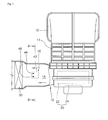
Fig. 1 , a conventional air conditioning system includes anair conditioning case 10 in which ablower 20 is installed. Theblower 20 includes ablower fan 22 and ablower motor 24 for driving theblower fan 22. Theblower 20 serves to inhale an external air or an internal air through an externalair inlet port 12 or an internalair inlet port 14 of theair conditioning case 10 and then to feed the inhaled air to aninternal passageway 16 of theair conditioning case 10. - The air conditioning system further includes an
evaporator 30 arranged inside theinternal passageway 16 of theair conditioning case 10. Theevaporator 30 includes a coolant tube (not shown) through which coolant can flow. Theevaporator 30 serves to cool the air passing through theinternal passageway 16 and also to introduce the cooled air into a vehicle room, thereby keeping the vehicle room at a pleasant temperature. - The air conditioning system further includes an
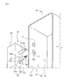
ionizer 40 for emitting positive ions and negative ions toward the air flowing through theinternal passageway 16. As illustrated inFigs. 1 and2 , theionizer 40 is installed on the upstream side of theevaporator 30 and includes amain body 42 attached to a side wall of theair conditioning case 10, first andsecond protection pipes main body 42 toward theinternal passageway 16 in a spaced-apart relationship with each other, and first andsecond discharge electrodes second protection pipes internal passageway 16. - The first and
second protection pipes hole 17 formed in theair conditioning case 10 and extend inwardly from aside wall 16a of theinternal passageway 16. The first andsecond discharge electrodes second protection pipes internal passageway 16 at their tip ends. The first andsecond discharge electrodes internal passageway 16. - The negative ions and positive ions generated in the
ionizer 40 are introduced into theevaporator 30 to sterilize bacteria and mold living in theevaporator 30 and also to deodorize the air supplied into the vehicle room, thereby enhancing the degree of cleanliness of the air introduced into the vehicle room and creating a comfortable vehicle room environment. - With the air conditioning system referred to above, however, moisture is condensed in and around the first and
second discharge electrodes ionizer 40 if the air introduced into theinternal passageway 16 has high humidity. The condensed moisture is infiltrated into the first andsecond discharge electrodes second discharge electrodes second discharge electrodes - In view of the above-noted problems, it is an object of the present invention to provide an air conditioning system for automotive vehicles capable of avoiding electric short between first and second discharge electrodes, which would otherwise be caused by ambient moisture.
- Another object of the present invention is to provide an air conditioning system for automotive vehicles capable of preventing generation of a spark between first and second discharge electrodes and an otherwise generated discharge noise.
- With the above objects in view, the present invention provides an air conditioning system for automotive vehicles, comprising: an air conditioning case having an internal passageway; an ionizer for emitting positive ions and negative ions into the internal passageway of the air conditioning case, the ionizer including a main body and first and second discharge electrodes extending from the main body into the internal passageway in a spaced-apart relationship with each other; and an electric short preventing means for preventing moisture condensed in and around the first and second discharge electrodes from causing electric short between the first and second discharge electrodes.
- The electric short preventing means may comprise a water drainage rib for draining the moisture condensed in and around the first and second discharge electrodes to prevent the electric short between the first and second discharge electrodes.
- The water drainage rib is adapted to drain the moisture condensed in and around a lower one of the first and second discharge electrodes and is joined to a side wall of the internal passageway so that the condensed moisture can be drained toward the side wall.
- In accordance with the present air conditioning system for automotive vehicles, there is provided a structure that prevents formation of a water film between the first and second discharge electrodes. This prevents electric short between the first and second discharge electrodes, which would otherwise generate a spark between the first and second discharge electrodes and a discharge noise. As a consequence, it becomes possible to greatly improve the driving comfortableness.
- The above and other objects and features of the present invention will become apparent from the following description of preferred embodiments, given in conjunction with the accompanying drawings, in which:
-
Fig. 1 is a section view showing a prior art air conditioning system; -
Fig. 2 is a section view taken along line II-II inFig. 1 ; -
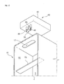
Fig. 3 is a bottom perspective view showing a first embodiment of a means for preventing electric short between first and second discharge electrodes, which is a characterizing part of an air conditioning system for automotive vehicles in accordance with the present invention; -
Fig. 4 is a section view taken along line IV-IV inFig. 3 ; -
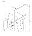
Figs. 5 to 10 are views illustrating modified examples of a water drainage rib that constitutes the means for preventing electric short between first and second discharge electrodes; -
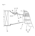
Figs. 11 and12 are section and bottom perspective views showing a second embodiment of a means for preventing electric short between first and second discharge electrodes; -
Figs. 13 and14 are section and bottom perspective views showing a modified example of an isolation baffle that constitutes the means for preventing electric short between first and second discharge electrodes in accordance with the second embodiment; -
Figs. 15 and16 are section and bottom perspective views showing a third embodiment of a means for preventing electric short between first and second discharge electrodes; -
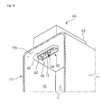
Figs. 17 and18 are section and bottom perspective views showing a fourth embodiment of a means for preventing electric short between first and second discharge electrodes; -
Figs. 19 and20 are section and bottom perspective views showing a fifth embodiment of a means for preventing electric short between first and second discharge electrodes; and -
Fig. 21 is a bottom perspective view showing a sixth embodiment of a means for preventing electric short between first and second discharge electrodes. - A preferred embodiment of an air conditioning system for automotive vehicles in accordance with the present invention will now be described in detail with reference to the accompanying drawings. The same reference numerals as used in describing the prior art will be used to designate the same elements as those of the prior art.
-
Fig. 3 is a bottom perspective view showing a characterizing part of an air conditioning system for automotive vehicles in accordance with the present invention.Fig. 4 is a section view taken along line IV-IV inFig. 3 . - Prior to describing a characterizing part of an air conditioning system for automotive vehicles in accordance with the present invention, a general aspect of the air conditioning system will be described with reference to
Figs. 1 ,3 and4 . - The air conditioning system includes an
air conditioning case 10 in which ablower 20 is installed. Theblower 20 inhales an external air or an internal air through an externalair inlet port 12 or an internalair inlet port 14 formed in theair conditioning case 10 and then feed the inhaled air to aninternal passageway 16 of theair conditioning case 10. - The air conditioning system includes an
evaporator 30 installed within theinternal passageway 16 of theair conditioning case 10. Theevaporator 30 serves to cool the air passing through theinternal passageway 16. The cooled air is introduced into a vehicle room, thereby keeping the vehicle room at a pleasant temperature. - The air conditioning system further includes an
ionizer 40 for emitting positive ions and negative ions toward the air flowing through theinternal passageway 16. Theionizer 40 is installed on the upstream side of theevaporator 30 and includes amain body 42 attached to an external surface of theair conditioning case 10, first andsecond protection pipes main body 42 toward theinternal passageway 16 in a spaced-apart relationship with each other, and first andsecond discharge electrodes second protection pipes internal passageway 16. - The first and
second protection pipes hole 17 formed in theair conditioning case 10 and extend inwardly from aside wall 16a of theinternal passageway 16. The first andsecond discharge electrodes second protection pipes internal passageway 16 at their tip ends. The first andsecond discharge electrodes internal passageway 16. - Next, the characterizing part of the present air conditioning system will be described in detail with reference to
Figs. 3 and4 . - The air conditioning system of the present invention includes an electric
short preventing means 50 for preventing electric short between the first andsecond discharge electrodes means 50 includes awater drainage rib 52 designed to drain the moisture existing between the first andsecond discharge electrodes - The
water drainage rib 52 is comprised of aconnection portion 52a connected to abottom surface 45a of thesecond protection pipe 45, i.e., the lower one of the first andsecond protection pipes water drainage portion 52b extending downwardly from theconnection portion 52a along a gravitational direction. - As can be seen in
Fig. 4 , thewater drainage portion 52b has a bottom slanting surface inclined toward theside wall 16a of theinternal passageway 16. Therefore, the bottom slanting surface is joined to theside wall 16a of theinternal passageway 16. Referring toFig. 3 , areception groove 16c for receiving thewater drainage rib 52 of thesecond protection pipe 45 is formed in theside wall 16a of theinternal passageway 16. - In case moisture is condensed in and around the
second protection pipe 45, thewater drainage rib 52 serves to rapidly drain the condensed moisture in a downward direction. At this time, the condensed moisture is guided toward and drained along theside wall 16a of theinternal passageway 16. - In this way, the moisture condensed in and around the
second protection pipe 45 is moved toward the base end of thesecond protection pipe 45 and is prevented from infiltrating into thesecond discharge electrode 48. This prevents formation of a water film between the first andsecond discharge electrodes - Since the formation of a water film between the first and
second discharge electrodes second discharge electrodes second discharge electrodes - Depending on the circumstances, the
water drainage rib 52 may be integrally formed with abottom surface 44a of thefirst protection pipe 44 as shown inFig. 5 . As in the foregoing embodiment, thewater drainage rib 52 provided in thebottom surface 44a of thefirst protection pipe 44 serves to downwardly drain the moisture condensed in and around thefirst protection pipe 44. - Therefore, the moisture is prevented from infiltrating into the
first discharge electrode 46 arranged within thefirst protection pipe 44. This prevents formation of a water film between the first andsecond discharge electrodes second discharge electrodes second discharge electrodes - It is preferred that the
water drainage rib 52 be formed on thebottom surface 45a of thesecond protection pipe 45 rather than thefirst protection pipe 44. The reason is that, if thewater drainage rib 52 is formed in thefirst protection pipe 44, the moisture drained from thewater drainage rib 52 may flow toward thesecond protection pipe 45 in a large quantity. - As a further alternative, two
water drainage ribs 52 may be formed on the bottom surfaces 44a and 45a of the first andsecond protection pipes Fig. 6 . In this case, it is possible to drain the moisture condensed in and around the first andsecond protection pipes -
Figs. 7 and8 are bottom perspective and section views illustrating a modified example of thewater drainage rib 52. Unlike the preceding embodiment, thewater drainage rib 52 of this modified example is integrally formed with theside wall 16a of theinternal passageway 16. Thewater drainage rib 52 of this modified example is comprised of aconnection portion 52a that makes contact with thebottom surface 45a of thesecond protection pipe 45 and awater drainage portion 52b extending downwardly from theconnection portion 52a along a gravitational direction. - The
water drainage rib 52 of this modified example serves to downwardly guide and drain the moisture flowing down from thebottom surface 45a of thesecond protection pipe 45. In particular, the moisture is guided along thewater drainage portion 52b and drained toward theside wall 16a of theinternal passageway 16. - Therefore, the moisture condensed in and around the
second protection pipe 45 is prevented from flowing toward the tip end of thesecond protection pipe 45 and infiltrating into thesecond discharge electrode 48. This prevents formation of a water film between the first andsecond discharge electrodes - As an alternative, the
water drainage rib 52 of this modified example may be arranged below thebottom surface 44a of thefirst protection pipe 44 as illustrated inFig. 9 . In this case, thewater drainage rib 52 serves to downwardly drain the moisture condensed in and around thefirst protection pipe 44. - Therefore, the moisture condensed in and around the
first protection pipe 44 is prevented from infiltrating into thefirst discharge electrode 46 arranged in thefirst protection pipe 44. This prevents formation of a water film between the first andsecond discharge electrodes - As a further alternative example, two
water drainage ribs 52 may be arranged below the bottom surfaces 44a and 45a of the first andsecond protection pipes Fig. 10 . In this case, it is possible to drain the whole moisture condensed in and around the first andsecond protection pipes - Referring next to
Figs. 11 and12 , there is shown a second embodiment of the electric short preventingmeans 50. The electric short preventingmeans 50 of the second embodiment is useful in case where theionizer 40 is installed in aceiling wall 16b of theinternal passageway 16. The electric short preventingmeans 50 includes anisolation baffle 60 arranged between the first andsecond discharge electrodes - The
isolation baffle 60 is integrally formed with the bottom surface of themain body 42 of theionizer 40. Theisolation baffle 60 is inserted through a through-hole 17 of theair conditioning case 10 together with the first andsecond discharge electrodes internal passageway 16. - The
isolation baffle 60 is formed in parallel with an air flow direction so as not to hinder the flow of air in theinternal passageway 16. Theisolation baffle 60 extends in a gravitational direction to downwardly guide and drain the moisture which would otherwise flow between the first andsecond discharge electrodes - Owing to the fact that the
isolation baffle 60 is designed to isolate the first andsecond discharge electrodes second discharge electrodes - This prevents formation of a water film between the first and
second discharge electrodes second discharge electrodes second discharge electrodes - Furthermore, since the
isolation baffle 60 is designed to downwardly drain the condensed moisture existing between the first andsecond discharge electrodes second discharge electrodes second discharge electrodes - Referring next to
Figs. 13 and14 , there is shown a modified example of theisolation baffle 60. Theisolation baffle 60 of the modified example is installed in theair conditioning case 10 so that it can be arranged between the first andsecond discharge electrodes isolation baffle 60 extends from the ceiling of theair conditioning case 10 into theinternal passageway 16. - In the same manner as described above, the
isolation baffle 60 of the modified example restrains the condensed moisture from flowing between the first andsecond discharge electrodes second discharge electrodes second discharge electrodes second discharge electrodes - In particular, the
isolation baffle 60 of the modified example is formed in parallel with an air flow direction so as not to hinder the flow of air in theinternal passageway 16. Theisolation baffle 60 extends in a gravitational direction to downwardly guide and drain the moisture which would otherwise flow between the first andsecond discharge electrodes - Referring next to
Figs. 15 and16 , there is shown a third embodiment of the electric short preventingmeans 50. The electric short preventingmeans 50 of the third embodiment includes a reinforcingrib 70 formed in the reinforcingrib 70 between the first andsecond discharge electrodes - The reinforcing
rib 70 is formed across theinternal passageway 16 so as to reinforce theair conditioning case 10. The reinforcingrib 70 is arranged to isolate the first andsecond discharge electrodes second discharge electrodes - This prevents formation of a water film between the first and
second discharge electrodes second discharge electrodes second discharge electrodes - In order for the reinforcing
rib 70 to be used as the electric short preventingmeans 50, there is a need to install theionizer 40 in alignment with the reinforcingrib 70. In other words, theionizer 40 needs to be mounted to theair conditioning case 10 in such a manner that the first andsecond discharge electrodes rib 70. - In this way, the electric short preventing
means 50 of the third embodiment makes use of the reinforcingrib 70 already formed with theair conditioning case 10. This eliminates the need to provide an additional component for isolating the first andsecond discharge electrodes means 50. - Referring next to
Figs. 17 and18 , there is shown a fourth embodiment of the electric short preventingmeans 50. The electric short preventingmeans 50 of the fourth embodiment is useful in case where theionizer 40 is installed in theceiling wall 16b of theinternal passageway 16. The electric short preventingmeans 50 includes amoisture isolation recess 80 formed in theceiling wall 16b to surround the first andsecond discharge electrodes - The
moisture isolation recess 80 is formed by upwardly indenting theceiling wall 16b around anelectrode insertion slot 17. Themoisture isolation recess 80 has a bottom surface positioned higher than the surface of theceiling wall 16b. Thus, themoisture isolation recess 80 serves to restrain the moisture from flowing from the remaining region of theceiling wall 16b toward the first andsecond discharge electrodes - This prevents the moisture condensed in the
ceiling wall 16b from flowing toward the first andsecond discharge electrodes second discharge electrodes second discharge electrodes second discharge electrodes - It is preferred that the
ceiling wall 16b on which themoisture isolation recess 80 is formed extends along a generally horizontal plane. This is to prevent the condensed moisture existing in aninclined ceiling wall 16d from flowing toward theceiling wall 16b on which themoisture isolation recess 80 is formed. Therefore, it is possible to restrain the condensed moisture from flowing from theinclined ceiling wall 16d toward the first andsecond discharge electrodes - Referring next to
Figs. 19 and20 , there is shown a fifth embodiment of the electric short preventingmeans 50. The electric short preventingmeans 50 of the fifth embodiment is useful in case where theionizer 40 is installed in theceiling wall 16b of theinternal passageway 16. The electric short preventingmeans 50 includes amoisture isolation wall 90 formed around the first andsecond discharge electrodes - The
moisture isolation wall 90 is integrally formed with theair conditioning case 10 in such a fashion that thetip end 92 thereof can face toward the bottom surface of theinternal passageway 16. Themoisture isolation wall 90 serves to downwardly guide and drain the moisture condensed in theceiling wall 16b of theinternal passageway 16. This prevents the moisture from flowing toward the first andsecond discharge electrodes second discharge electrodes - Consequently, this makes it possible to avoid formation of a water film between the first and
second discharge electrodes second discharge electrodes second discharge electrodes - Referring next to
Fig. 21 , there is shown a sixth embodiment of the electric short preventingmeans 50. The electric short preventingmeans 50 of the sixth embodiment includes a plurality ofwater drainage protrusions 100 arranged around the first andsecond discharge electrodes water drainage protrusions 100 protrudes in a gravitational direction. - Each of the
water drainage protrusions 100 is integrally formed with theair conditioning case 10 in such a fashion that the tip end thereof can face toward the bottom surface of theinternal passageway 16. - The
water drainage protrusions 100 serve to downwardly guide and drain the moisture condensed in theceiling wall 16b of theinternal passageway 16. This prevents the moisture from flowing toward the first andsecond discharge electrodes second discharge electrodes - While certain preferred embodiments of the invention have been described hereinabove, the present invention is not limited to these embodiments. It is to be understood that various changes and modifications may be made without departing from the scope of the invention defined in the claims.
Claims (15)
- An air conditioning system for automotive vehicles, comprising: an air conditioning case (10) having an internal passageway (16); and an ionizer (40) for emitting positive ions and negative ions into the internal passageway (16) of the air conditioning case (10), the ionizer (10) including a main body (42) and first and second discharge electrodes (46, 48) extending from the main body (42) into the internal passageway (16) in a spaced-apart relationship with each other, characterized by further comprising:an electric short preventing means (50) for preventing moisture positioned in and around the first and second discharge electrodes (46, 48) from causing electric short between the first and second discharge electrodes (46, 48).
- The air conditioning system according to claim 1, characterized in that the electric short preventing means (50) comprises a water drainage rib (52) for draining the moisture positioned in and around the first and second discharge electrodes (46, 48) to prevent the electric short between the first and second discharge electrodes (46, 48).
- The air conditioning system according to claim 2, characterized in that the water drainage rib (52) is adapted to drain the moisture positioned in and around a lower one of the first and second discharge electrodes (46, 48).
- The air conditioning system according to claim 3, characterized in that the water drainage rib (52) is joined to a side wall (16a) of the internal passageway (16) so that the moisture can be drained toward the side wall (16a).
- The air conditioning system according to any one of claims 2 to 4, characterized in that the water drainage rib (52) is integrally formed with the ionizer (40) or the water drainage rib (52) is integrally formed with the air conditioning case (10).
- The air conditioning system according to claim 1, characterized in that the electric short preventing means (50) comprises an isolation baffle (60) for restraining the moisture from flowing between the first and second discharge electrodes (46, 48) to prevent the electric short between the first and second discharge electrodes (46, 48).
- The air conditioning system according to claim 6, characterized in that the isolation baffle (60) is arranged between the first and second discharge electrodes (46, 48) and protrudes from the main body (42) into the internal passageway (16).
- The air conditioning system according to claim 6, characterized in that the isolation baffle (60) is arranged between the first and second discharge electrodes (46, 48) and protrudes from the air conditioning case (10) into the internal passageway (16).
- The air conditioning system according to any one of claims 6 to 8, characterized in that the isolation baffle (60) is formed in parallel with an air flow direction and extends in a gravitational direction so that the moisture existing between the first and second discharge electrodes (46, 48) can be drained downwardly.
- The air conditioning system according to claim 1, characterized in that the electric short preventing means (50) comprises a reinforcing rib (70) formed in the air conditioning case (10), the reinforcing rib (70) arranged between the first and second discharge electrodes (46, 48) so that the reinforcing rib (70) can restrain the moisture from flowing between the first and second discharge electrodes (46, 48) to prevent the electric short between the first and second discharge electrodes (46, 48), the first and second discharge electrodes (46, 48) mounted to the air conditioning case (10) on the both sides of the reinforcing rib (70).
- The air conditioning system according to claim 1, characterized in that the electric short preventing means (50) comprises a moisture isolation recess (80) formed in the air conditioning case (10) around the first and second discharge electrodes (46, 48) so that the moisture isolation recess (80) can restrain the moisture from flowing toward the first and second discharge electrodes (46, 48) to prevent the electric short between the first and second discharge electrodes (46, 48).
- The air conditioning system according to claim 11, characterized in that the moisture isolation recess (80) is formed by upwardly indenting the air conditioning case (10) around the first and second discharge electrodes (46, 48).
- The air conditioning system according to claim 1, characterized in that the electric short preventing means (50) comprises a moisture isolation wall (90) formed around the first and second discharge electrodes (46, 48) so that the moisture isolation wall (90) can restrain the moisture from flowing toward the first and second discharge electrodes (46, 48) to prevent the electric short between the first and second discharge electrodes (46, 48).
- The air conditioning system according to claim 13, characterized in that the moisture isolation wall (90) is formed in the air conditioning case (10) around the first and second discharge electrodes (46, 48) so that the moisture isolation wall (90) can downwardly drain the moisture flowing toward the first and second discharge electrodes (46, 48).
- The air conditioning system according to claim 1, characterized in that the electric short preventing means (50) comprises a plurality of water drainage protrusions (100) formed around the first and second discharge electrodes (46, 48) so that the water drainage protrusions (100) can restrain the moisture from flowing toward the first and second discharge electrodes (46, 48) to prevent the electric short between the first and second discharge electrodes (46, 48).
Priority Applications (2)
| Application Number | Priority Date | Filing Date | Title |
|---|---|---|---|
| EP10195955A EP2289719B1 (en) | 2007-04-12 | 2008-04-09 | Air conditioning system for automotive vehicles |
| EP10195947A EP2289718B1 (en) | 2007-04-12 | 2008-04-09 | Air conditioning system for automotive vehicles |
Applications Claiming Priority (3)
| Application Number | Priority Date | Filing Date | Title |
|---|---|---|---|
| KR1020070035924A KR100903312B1 (en) | 2007-04-12 | 2007-04-12 | Car air conditioner |
| KR1020070036273A KR100903313B1 (en) | 2007-04-13 | 2007-04-13 | Air conditioning case of vehicle air conditioning system |
| KR1020070044606A KR100903314B1 (en) | 2007-05-08 | 2007-05-08 | Car air conditioner |
Related Child Applications (2)
| Application Number | Title | Priority Date | Filing Date |
|---|---|---|---|
| EP10195955.9 Division-Into | 2010-12-20 | ||
| EP10195947.6 Division-Into | 2010-12-20 |
Publications (3)
| Publication Number | Publication Date |
|---|---|
| EP1980430A2 true EP1980430A2 (en) | 2008-10-15 |
| EP1980430A3 EP1980430A3 (en) | 2009-07-15 |
| EP1980430B1 EP1980430B1 (en) | 2011-09-14 |
Family
ID=39628751
Family Applications (3)
| Application Number | Title | Priority Date | Filing Date |
|---|---|---|---|
| EP10195947A Ceased EP2289718B1 (en) | 2007-04-12 | 2008-04-09 | Air conditioning system for automotive vehicles |
| EP10195955A Ceased EP2289719B1 (en) | 2007-04-12 | 2008-04-09 | Air conditioning system for automotive vehicles |
| EP08007053A Ceased EP1980430B1 (en) | 2007-04-12 | 2008-04-09 | Air conditioning system for automotive vehicles |
Family Applications Before (2)
| Application Number | Title | Priority Date | Filing Date |
|---|---|---|---|
| EP10195947A Ceased EP2289718B1 (en) | 2007-04-12 | 2008-04-09 | Air conditioning system for automotive vehicles |
| EP10195955A Ceased EP2289719B1 (en) | 2007-04-12 | 2008-04-09 | Air conditioning system for automotive vehicles |
Country Status (3)
| Country | Link |
|---|---|
| US (1) | US7749313B2 (en) |
| EP (3) | EP2289718B1 (en) |
| JP (3) | JP4743446B2 (en) |
Families Citing this family (18)
| Publication number | Priority date | Publication date | Assignee | Title |
|---|---|---|---|---|
| WO2007078135A1 (en) * | 2005-12-30 | 2007-07-12 | Halla Climate Control Corp. | Vehicle air purifier with a negative and positive ion generator and air conditioning system using the same |
| US8564924B1 (en) | 2008-10-14 | 2013-10-22 | Global Plasma Solutions, Llc | Systems and methods of air treatment using bipolar ionization |
| US8713959B2 (en) * | 2009-11-25 | 2014-05-06 | Panasonic Corporation | Heat generating body box housing refrigeration device |
| JP5492674B2 (en) * | 2010-06-25 | 2014-05-14 | 日立アプライアンス株式会社 | Induction heating cooker |
| JP2012067935A (en) * | 2010-09-21 | 2012-04-05 | Sharp Corp | Refrigerator |
| CN105492836B (en) * | 2014-01-23 | 2018-05-01 | 夏普株式会社 | Air conditioner |
| CN104654494A (en) * | 2014-06-26 | 2015-05-27 | 柳州市安龙机械设备有限公司 | Automotive air conditioner exhaust fan |
| JP6723682B2 (en) * | 2014-11-07 | 2020-07-15 | レルテック医療器株式会社 | Negative ion generator |
| US9847623B2 (en) | 2014-12-24 | 2017-12-19 | Plasma Air International, Inc | Ion generating device enclosure |
| WO2017085954A1 (en) | 2015-11-20 | 2017-05-26 | 株式会社デンソー | Vehicle air-conditioning device |
| DE202015106952U1 (en) * | 2015-12-21 | 2017-03-22 | Rehau Ag + Co | Air guide arrangement |
| US9660425B1 (en) | 2015-12-30 | 2017-05-23 | Plasma Air International, Inc | Ion generator device support |
| KR101762804B1 (en) * | 2016-02-15 | 2017-07-28 | 엘지전자 주식회사 | An airconditioning system for vehicles |
| DE102017121202A1 (en) * | 2017-09-13 | 2019-03-14 | Valeo Klimasysteme Gmbh | Vehicle air-conditioning outlet unit |
| KR102573538B1 (en) * | 2017-11-28 | 2023-09-01 | 한온시스템 주식회사 | Air conditioning system for automotive vehicles |
| CN113418325A (en) * | 2021-07-08 | 2021-09-21 | 平流层复合水离子(深圳)有限公司 | High-pressure ionized water molecule self-cleaning evaporator |
| DE102022202649A1 (en) | 2022-03-17 | 2023-09-21 | Mahle International Gmbh | System for a ventilation device |
| CN117190480A (en) * | 2023-09-04 | 2023-12-08 | 柳州中建科工会展运营管理有限公司 | A drainage system for central air conditioning |
Citations (2)
| Publication number | Priority date | Publication date | Assignee | Title |
|---|---|---|---|---|
| JP2004105415A (en) | 2002-09-18 | 2004-04-08 | Sakae Riken Kogyo Co Ltd | Air cleaning filter apparatus |
| KR20060102226A (en) | 2005-03-23 | 2006-09-27 | 한라공조주식회사 | Automotive air conditioner with cluster negative ion generator |
Family Cites Families (52)
| Publication number | Priority date | Publication date | Assignee | Title |
|---|---|---|---|---|
| US3936698A (en) * | 1970-03-20 | 1976-02-03 | Meyer George F | Ion generating apparatus |
| JPS521246Y2 (en) * | 1971-08-24 | 1977-01-12 | ||
| US3957374A (en) * | 1974-02-01 | 1976-05-18 | Carl Zeiss-Stiftung | Apparatus for obtaining samples of dusts for analysis by spectrochemical examination |
| US3942072A (en) * | 1974-10-18 | 1976-03-02 | Burlington Industries, Inc. | Method and system for maintaining an electrically neutral atmosphere |
| JPS532767A (en) * | 1976-06-30 | 1978-01-11 | Hitachi Plant Eng & Constr Co Ltd | Discharging electrode for electric dust collector |
| JPS6018812U (en) | 1983-07-19 | 1985-02-08 | カルソニックカンセイ株式会社 | Automotive air conditioner |
| JPS6439815A (en) * | 1987-08-05 | 1989-02-10 | Sharp Kk | Noise eliminating circuit |
| JPH03188867A (en) * | 1989-12-19 | 1991-08-16 | Toto Ltd | Ozone deodorizing device |
| JPH04114752A (en) * | 1990-09-04 | 1992-04-15 | Matsushita Electric Ind Co Ltd | air purifier |
| US5065272A (en) * | 1991-01-09 | 1991-11-12 | Elexis Corporation | Air ionizer |
| JPH057857U (en) * | 1991-07-19 | 1993-02-02 | 積水化学工業株式会社 | Bathroom unit |
| JPH0547489A (en) * | 1991-08-12 | 1993-02-26 | Kitagawa Ind Co Ltd | Ion generation device for preventing charging |
| JP2904328B2 (en) * | 1992-11-24 | 1999-06-14 | 三菱電機株式会社 | Microbial propagation prevention device |
| US5332425A (en) * | 1993-02-22 | 1994-07-26 | Hung Hsing Electric Co., Ltd. | Air purifier |
| JPH0834229A (en) * | 1994-07-21 | 1996-02-06 | Zexel Corp | Air purifier |
| JP3007343U (en) * | 1994-07-29 | 1995-02-14 | 福島 文雄 | Ion generator |
| US5707429A (en) * | 1996-09-25 | 1998-01-13 | Lewis Lint Trap, Inc. | Ionizing structure for ambient air treatment |
| JP3046951B2 (en) * | 1998-04-27 | 2000-05-29 | 株式会社セイスイ | Air purifier |
| JP2000247141A (en) | 1999-03-01 | 2000-09-12 | Zexel Corp | Negative ion generating device of air conditioning system |
| KR20000067602A (en) | 1999-04-30 | 2000-11-25 | 구자홍 | Protection assembly for power device in outdoor unit |
| JP3059438B1 (en) * | 1999-05-31 | 2000-07-04 | 株式会社オーデン | Electric dust collection unit |
| FR2794295B1 (en) * | 1999-05-31 | 2001-09-07 | Joel Mercier | ION GENERATING DEVICE |
| US6464754B1 (en) * | 1999-10-07 | 2002-10-15 | Kairos, L.L.C. | Self-cleaning air purification system and process |
| JP3287468B2 (en) * | 1999-11-15 | 2002-06-04 | 株式会社オーデン | Electric dust collection unit |
| US6294004B1 (en) * | 1999-12-21 | 2001-09-25 | Engineering Dynamics Ltd. | Structures for electrostatic V-bank air filters |
| DE10033642C1 (en) * | 2000-07-11 | 2001-08-09 | Hengst Walter Gmbh & Co Kg | Electrical separator |
| RU2182523C1 (en) * | 2001-02-08 | 2002-05-20 | Общество с ограниченной ответственностью "ВИНТЕЛ" | Device for accumulating of aerosols from gases |
| JP4903942B2 (en) * | 2001-03-15 | 2012-03-28 | 株式会社キーエンス | Ion generator |
| JP2003142228A (en) * | 2001-11-02 | 2003-05-16 | Yamatake Corp | Negative ion generator |
| JP2003187945A (en) | 2001-12-13 | 2003-07-04 | Nippon Gureen Kenkyusho:Kk | Air ion generator and supply method of air ion |
| JP2003229678A (en) * | 2002-01-31 | 2003-08-15 | Denso Corp | Housing structure of electronic control unit |
| JP2004028499A (en) * | 2002-06-27 | 2004-01-29 | Hitachi Home & Life Solutions Inc | refrigerator |
| JP2004074859A (en) * | 2002-08-12 | 2004-03-11 | Denso Corp | Negative ion generator with air purification function |
| JP4144788B2 (en) * | 2002-11-19 | 2008-09-03 | 九州日立マクセル株式会社 | Hairdressing tools |
| JP2004189147A (en) * | 2002-12-12 | 2004-07-08 | Altia Co Ltd | Minus ion generator for vehicle |
| KR20040073038A (en) | 2003-02-12 | 2004-08-19 | 한라공조주식회사 | Air conditioner for vehicle |
| JP4239692B2 (en) * | 2003-06-04 | 2009-03-18 | パナソニック電工株式会社 | Air cleaner |
| JP2005014789A (en) * | 2003-06-26 | 2005-01-20 | Nissan Motor Co Ltd | Antistatic device |
| JP4311631B2 (en) * | 2003-09-25 | 2009-08-12 | シャープ株式会社 | Ion diffusion device |
| JP5053640B2 (en) * | 2003-11-17 | 2012-10-17 | アブサルート エコロジー エスタブリッシュメント | Apparatus and method for decomposing and removing airborne oxidized particles |
| US6991532B2 (en) * | 2003-12-09 | 2006-01-31 | Valeo Climate Control Corp. | Method and apparatus for decontamination for automotive HVAC systems |
| JP4365201B2 (en) * | 2003-12-22 | 2009-11-18 | 共立電器産業株式会社 | Air cleaning activator |
| JP2005289177A (en) | 2004-03-31 | 2005-10-20 | Calsonic Kansei Corp | Air conditioner |
| US6955708B1 (en) * | 2004-08-13 | 2005-10-18 | Shaklee Corporation | Air-treatment apparatus and methods |
| JP2006244687A (en) * | 2005-02-07 | 2006-09-14 | Matsushita Electric Ind Co Ltd | Recording device |
| JP4720413B2 (en) * | 2005-03-07 | 2011-07-13 | パナソニック株式会社 | Air conditioner |
| WO2006106594A1 (en) * | 2005-04-04 | 2006-10-12 | Shimizu Corporation | Air ion conveyance device and air ion conveyance system |
| JP2006290001A (en) * | 2005-04-05 | 2006-10-26 | Denso Corp | Vehicle air purifier |
| FR2888054A1 (en) * | 2005-07-04 | 2007-01-05 | Genie Et Environnement Sarl | ION GENERATING DEVICE |
| US7537647B2 (en) * | 2005-08-10 | 2009-05-26 | S.C. Johnson & Son, Inc. | Air purifier |
| US7601204B2 (en) * | 2006-09-06 | 2009-10-13 | Trane International Inc. | Air conditioning apparatus with integrated air filtration system |
| US7497898B2 (en) * | 2006-10-31 | 2009-03-03 | Smc Corporation | Ionizer |
-
2008
- 2008-04-08 JP JP2008100371A patent/JP4743446B2/en not_active Expired - Fee Related
- 2008-04-09 EP EP10195947A patent/EP2289718B1/en not_active Ceased
- 2008-04-09 EP EP10195955A patent/EP2289719B1/en not_active Ceased
- 2008-04-09 EP EP08007053A patent/EP1980430B1/en not_active Ceased
- 2008-04-10 US US12/101,067 patent/US7749313B2/en active Active
-
2011
- 2011-03-30 JP JP2011076219A patent/JP5244939B2/en not_active Expired - Fee Related
- 2011-03-30 JP JP2011076218A patent/JP5449244B2/en active Active
Patent Citations (2)
| Publication number | Priority date | Publication date | Assignee | Title |
|---|---|---|---|---|
| JP2004105415A (en) | 2002-09-18 | 2004-04-08 | Sakae Riken Kogyo Co Ltd | Air cleaning filter apparatus |
| KR20060102226A (en) | 2005-03-23 | 2006-09-27 | 한라공조주식회사 | Automotive air conditioner with cluster negative ion generator |
Also Published As
| Publication number | Publication date |
|---|---|
| JP4743446B2 (en) | 2011-08-10 |
| JP2011126541A (en) | 2011-06-30 |
| EP2289719A1 (en) | 2011-03-02 |
| JP2008260520A (en) | 2008-10-30 |
| JP5244939B2 (en) | 2013-07-24 |
| EP1980430B1 (en) | 2011-09-14 |
| JP5449244B2 (en) | 2014-03-19 |
| EP2289718B1 (en) | 2012-02-15 |
| EP2289719B1 (en) | 2012-02-15 |
| JP2011126540A (en) | 2011-06-30 |
| US7749313B2 (en) | 2010-07-06 |
| US20080251236A1 (en) | 2008-10-16 |
| EP1980430A3 (en) | 2009-07-15 |
| EP2289718A1 (en) | 2011-03-02 |
Similar Documents
| Publication | Publication Date | Title |
|---|---|---|
| US7749313B2 (en) | Air conditioning system for automotive vehicles | |
| CN101284489B (en) | Air conditioning system for automotive vehicles | |
| CN103648809B (en) | Interior environment system and railway vehicle | |
| US20140029155A1 (en) | Ion generator mounting device | |
| JP4722165B2 (en) | Air conditioner | |
| CN104093990A (en) | Sound-proofing housing for a respirator | |
| GB2534013A (en) | Power converter and rolling stock including the same | |
| KR100903314B1 (en) | Car air conditioner | |
| KR100914416B1 (en) | Ionizer of air conditioning system for automotive vehicles | |
| JP3876864B2 (en) | Indoor unit of air conditioner | |
| JP2023024436A (en) | Air conditioning indoor unit and air conditioner | |
| JP6398726B2 (en) | Blower | |
| JP2003156228A (en) | Air conditioner | |
| JP2001201169A (en) | Air conditioner and air cleaner | |
| JP2004141848A (en) | Ion generator and air conditioner | |
| JP2014020578A (en) | Air conditioner | |
| JP2003222339A (en) | High frequency heating equipment | |
| KR101565406B1 (en) | Air conditioner | |
| KR20030000418A (en) | A filter's installation structure of the air-conditioner | |
| JP2004197439A (en) | Ventilation structure of building | |
| KR100529920B1 (en) | An indoor unit of duct type air-conditioner | |
| JP2005214596A (en) | Blower | |
| WO2016002972A1 (en) | Air purifier | |
| KR20090071029A (en) | Car air conditioner | |
| JPH10193957A (en) | Ceiling cooler unit for vehicles |
Legal Events
| Date | Code | Title | Description |
|---|---|---|---|
| PUAI | Public reference made under article 153(3) epc to a published international application that has entered the european phase |
Free format text: ORIGINAL CODE: 0009012 |
|
| AK | Designated contracting states |
Kind code of ref document: A2 Designated state(s): AT BE BG CH CY CZ DE DK EE ES FI FR GB GR HR HU IE IS IT LI LT LU LV MC MT NL NO PL PT RO SE SI SK TR |
|
| AX | Request for extension of the european patent |
Extension state: AL BA MK RS |
|
| PUAL | Search report despatched |
Free format text: ORIGINAL CODE: 0009013 |
|
| AK | Designated contracting states |
Kind code of ref document: A3 Designated state(s): AT BE BG CH CY CZ DE DK EE ES FI FR GB GR HR HU IE IS IT LI LT LU LV MC MT NL NO PL PT RO SE SI SK TR |
|
| AX | Request for extension of the european patent |
Extension state: AL BA MK RS |
|
| 17P | Request for examination filed |
Effective date: 20100108 |
|
| 17Q | First examination report despatched |
Effective date: 20100223 |
|
| AKX | Designation fees paid |
Designated state(s): DE FR GB |
|
| GRAP | Despatch of communication of intention to grant a patent |
Free format text: ORIGINAL CODE: EPIDOSNIGR1 |
|
| GRAS | Grant fee paid |
Free format text: ORIGINAL CODE: EPIDOSNIGR3 |
|
| GRAA | (expected) grant |
Free format text: ORIGINAL CODE: 0009210 |
|
| AK | Designated contracting states |
Kind code of ref document: B1 Designated state(s): DE FR GB |
|
| REG | Reference to a national code |
Ref country code: GB Ref legal event code: FG4D |
|
| REG | Reference to a national code |
Ref country code: DE Ref legal event code: R096 Ref document number: 602008009696 Country of ref document: DE Effective date: 20111124 |
|
| PLBE | No opposition filed within time limit |
Free format text: ORIGINAL CODE: 0009261 |
|
| STAA | Information on the status of an ep patent application or granted ep patent |
Free format text: STATUS: NO OPPOSITION FILED WITHIN TIME LIMIT |
|
| 26N | No opposition filed |
Effective date: 20120615 |
|
| REG | Reference to a national code |
Ref country code: DE Ref legal event code: R097 Ref document number: 602008009696 Country of ref document: DE Effective date: 20120615 |
|
| REG | Reference to a national code |
Ref country code: DE Ref legal event code: R082 Ref document number: 602008009696 Country of ref document: DE Representative=s name: KOEPE & PARTNER PATENTANWAELTE, DE |
|
| REG | Reference to a national code |
Ref country code: FR Ref legal event code: CD Owner name: HALLA VISTEON CLIMATE CONTROL CORPORATION Effective date: 20130827 |
|
| REG | Reference to a national code |
Ref country code: DE Ref legal event code: R082 Ref document number: 602008009696 Country of ref document: DE Representative=s name: SCHWABE SANDMAIR MARX PATENTANWAELTE RECHTSANW, DE Effective date: 20130910 Ref country code: DE Ref legal event code: R081 Ref document number: 602008009696 Country of ref document: DE Owner name: HANON SYSTEMS, KR Free format text: FORMER OWNER: HALLA CLIMATE CONTROL CORP., DAEJEON, KR Effective date: 20130910 Ref country code: DE Ref legal event code: R082 Ref document number: 602008009696 Country of ref document: DE Representative=s name: KOEPE & PARTNER PATENTANWAELTE, DE Effective date: 20130910 Ref country code: DE Ref legal event code: R081 Ref document number: 602008009696 Country of ref document: DE Owner name: HALLA VISTEON CLIMATE CONTROL CORP., KR Free format text: FORMER OWNER: HALLA CLIMATE CONTROL CORP., DAEJEON, KR Effective date: 20130910 |
|
| REG | Reference to a national code |
Ref country code: FR Ref legal event code: PLFP Year of fee payment: 9 |
|
| REG | Reference to a national code |
Ref country code: DE Ref legal event code: R082 Ref document number: 602008009696 Country of ref document: DE Representative=s name: SCHWABE SANDMAIR MARX PATENTANWAELTE RECHTSANW, DE Ref country code: DE Ref legal event code: R082 Ref document number: 602008009696 Country of ref document: DE Representative=s name: SSM SANDMAIR PATENTANWAELTE RECHTSANWALT PARTN, DE |
|
| REG | Reference to a national code |
Ref country code: DE Ref legal event code: R082 Ref document number: 602008009696 Country of ref document: DE Representative=s name: SCHWABE SANDMAIR MARX PATENTANWAELTE RECHTSANW, DE Ref country code: DE Ref legal event code: R081 Ref document number: 602008009696 Country of ref document: DE Owner name: HANON SYSTEMS, KR Free format text: FORMER OWNER: HALLA VISTEON CLIMATE CONTROL CORP., DAEJEON, KR Ref country code: DE Ref legal event code: R082 Ref document number: 602008009696 Country of ref document: DE Representative=s name: SSM SANDMAIR PATENTANWAELTE RECHTSANWALT PARTN, DE |
|
| REG | Reference to a national code |
Ref country code: FR Ref legal event code: CD Owner name: HANON SYSTEMS Effective date: 20161212 |
|
| REG | Reference to a national code |
Ref country code: FR Ref legal event code: PLFP Year of fee payment: 10 |
|
| REG | Reference to a national code |
Ref country code: FR Ref legal event code: PLFP Year of fee payment: 11 |
|
| P01 | Opt-out of the competence of the unified patent court (upc) registered |
Effective date: 20230615 |
|
| PGFP | Annual fee paid to national office [announced via postgrant information from national office to epo] |
Ref country code: GB Payment date: 20240215 Year of fee payment: 17 |
|
| PGFP | Annual fee paid to national office [announced via postgrant information from national office to epo] |
Ref country code: FR Payment date: 20240213 Year of fee payment: 17 |
|
| PGFP | Annual fee paid to national office [announced via postgrant information from national office to epo] |
Ref country code: DE Payment date: 20240213 Year of fee payment: 17 |
|
| REG | Reference to a national code |
Ref country code: DE Ref legal event code: R119 Ref document number: 602008009696 Country of ref document: DE |
|
| GBPC | Gb: european patent ceased through non-payment of renewal fee |
Effective date: 20250409 |
|
| PG25 | Lapsed in a contracting state [announced via postgrant information from national office to epo] |
Ref country code: DE Free format text: LAPSE BECAUSE OF NON-PAYMENT OF DUE FEES Effective date: 20251104 |
|
| PG25 | Lapsed in a contracting state [announced via postgrant information from national office to epo] |
Ref country code: GB Free format text: LAPSE BECAUSE OF NON-PAYMENT OF DUE FEES Effective date: 20250409 |
|
| PG25 | Lapsed in a contracting state [announced via postgrant information from national office to epo] |
Ref country code: FR Free format text: LAPSE BECAUSE OF NON-PAYMENT OF DUE FEES Effective date: 20250430 |