-
The present invention relates to a bending machine, which is intended for bending material, and which includes bending elements, as well as an apparatus for operating and controlling the bending machine, measuring elements being connected to the bending elements, for determining the bending angle when operating the bending machine.
-
So called free bending, which is also referred to as air-gap bending, is used particularly when bending metallic sheet and bar material. In bending of this kind, the blank being bent only touches the two points of the die, and the ram. Free pressing permits a large number of different pieces to be manufactured using a small number of tools, by only altering the control setting of the bending machine and/or by changing the die and ram. In practice, spring-back of the blank occurs in free pressing, which is taken into account by using a sufficient amount of over bending. The magnitude of the spring-back depends on several variables, for example, the thickness, grade, and hardness of the material, as well as the bending angle.
-
Modern bending machines are numerically controlled and largely automated. In other words, after making the settings even large batches of similar blanks can be bent rapidly and accurately. The settings can concern directly the operating device driving the ram, which can, however, lead to inaccuracies in the finished product. Thus various ways have been developed to determine the real bending angle, which can in turn be used to control the bending machine. The question is then of a kind of feedback, by means of which good bending accuracy can be achieved in relation to the bending angle.
-
German utility model number
8234901 discloses a bending machine, which is equipped with an electronic angle measuring system. The two points of the die are formed from two flattened parallel die pins, which are arranged to rotate around their longitudinal axes. In bending, each die pin rotates in the opposite direction and the angles of rotation of both are measured. By summing these angles of rotation, the bending angle reached is measured, and is utilized, for example, as feedback in the control devices. This preserves the accuracy of the bending machine, despite possible disturbances in the structure or operation of the bending machine. In addition to sheet and bar material, various profiles and pipes are also bent.
US patent number 5259224 discloses a pipe-bending machine, in which the end of the pipe is locked in the jaws of the die. The rest of the pipe is supported on the ram. When operating the pipe-bending machine, the die rotates and the ram moves. Measuring elements are fitted in connection with both of these, in order to determine the real bending angle. There can also be several dies.
-
Electronic elements for measuring the angle of rotation are integrated in the die. In such a case, the die becomes large and there must be electronic elements in each die. In addition, each die must also have its own operating device to return the die pins. This increases the purchase and operating costs of the bending machine. Also the die itself is an expensive tool. Correspondingly, in terms of the use of the bending machine a significant drawback is the location of electronic elements in the working area. In other words, the elements are in danger of being broken when the blank is placed in, or removed from the bending machine. Sometimes the elements can even entirely prevent the blank from being placed in the bending machine. In addition, when changing the dies electrical and pneumatic connections must be made. At the same time, erroneous connections are possible. The same problems appear in other bending machines too. For example, in the pipe-bending machine it is difficult to change the die and a poor contact between the measuring element and the die can lead to inaccuracies. In addition, the measuring elements can be broken when the pipe is being placed or removed.
-
The invention is intended to create a new type of bending machine, by means of which the drawbacks of the prior art can be avoided. The characteristic features of the present invention are stated in the accompanying Claims. In the bending machine according to the invention, the measuring elements are located in a new and surprising manner, so that their breakage is avoided. At the same time, the bending elements can be made simpler and cheaper than previously. The measuring elements can be used in connection with various kinds of bending elements while the changing of the bending elements is simple and quick. Further, the measuring elements can be fitted to very different kinds of bending machine. The measuring elements according to the invention can also be used in manually controlled bending machines.
-
In the following, the invention is described in detail with reference to the accompanying drawings showing some embodiments of the invention, in which
- Figure 1
- shows a schematic drawings of the bending machine according to the invention,
- Figure 2a
- shows the die and ram of the bending machine according to the invention, prior to the work stroke,
- Figure 2b
- shows the ram of Figure 2a at the end of the work stroke,
- Figure 3
- shows the arrangement according to the invention in connection with the die pin, with the components separated from each other, and
- Figure 4
- shows a second embodiment of the arrangement according to the invention, according to Figure 3.
-
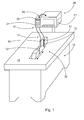
Generally, a bending machine intended for bending a material includes bending elements and an apparatus for operating and controlling the bending machine. In addition, measuring elements are connected to the bending elements, for determining the bending angle when operating the bending machine. According to the invention, the measuring elements are fitted structurally separately from the bending elements and the measuring elements are connected to the bending elements by means of a rotationally rigid connecting element. The bending machine, intended for the free bending of sheet or bar material, is shown in Figure 1. The invention can also be applied in other bending machines, for example, in profile and pipe-bending machines.
-
In Figure 1, the bending machine includes, as bending elements 32, a die 11 and a ram 12. Also included is an apparatus 13 for operating and controlling the bending machine. In Figure 1, the ram moves horizontally, so that the plane 14 belonging to the bending machine can be used to support the blank being bent. Alternatively, the ram is often arranged to move vertically. In any event, the ram generally performs the actual work movement while the die remains stationary. On the other hand, the die too can have various directions of movement, but these are largely intended for positioning the die in the desired manner.
-
Often certain kinds of die are used, in which the two points of the die are formed from flattened die pins. In that case, the parallel die pins rotate around their longitudinal axes when the die is used for bending. Especially to achieve high precision, it will be desired to know the real bending angle reached. For this reason, measuring elements 16, which are arranged to measure the angle of rotation of the die pins 15, are connected to the die pins 15. In other words, the difference in angle of the die pins 15 is defined, in order to determine the bending angle reached. According to the invention, the measuring elements 16 are fitted structurally separately from the die 11. In other words, the measuring elements are not attached to the die. This avoids the measuring elements being broken during bending, or when the blank is set in place or removed. At the same time, it is possible to use simpler dies than previously, which for its part reduces the purchase and operating costs of the bending machine. According to the invention, the measuring elements 16 are, in addition, connected to the die pins 15 by means of a rotationally rigid connector element 17. In addition, the connector element 17 is preferably flexible. Thus the measuring elements can be freely located. If necessary, the die too can be arranged to be moveable. The rotational angle of the die pins will also be transmitted accurately, despite the distance of the measuring elements.
-
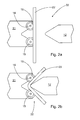
According to the invention, the connector element 17 is attached to the die pins 15, or more generally to the bending elements, in a quick-release manner. Thus, when changing the die the connector element can be detached and connected without the use of tools. Figures 2a, 2b, 3 and 4 show a square hole 18 machined in the end of the die pin 15, a corresponding square pin 19 being arranged in the end of the connector element 17 (Figures 3 and 4). Thus the quick-release attachment is preferably based on shape locking, the shape of which can, of course, vary in different applications. The shape locking is ensured by using a sufficiently tight fit, or separate locking. The essential feature is, however, a lack of clearance in the direction of rotation, to preserve precision.
-
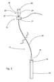
The die pins and measuring elements can be connected to each other in different ways. The apparatus preferably includes one connector element 17 and one measuring element 16 for each die pin 15, Thus the construction of the arrangement is kept simple and the angle of rotation of each die pin can be determined precisely. Figure 3 shows the arrangement according to the invention, in the case of one die pin 15. According to the invention, the connector element 17 is a mechanical cable shaft 20, which is flexible, but which transmits accurately the mechanical rotational movement of the die pin to the measuring element. The rotational angle can also be determined using different kinds of measuring element, which are preferably electronic or mechanical angle sensors. According to the invention, the measuring element 16 is preferably a pulse sensor 21.
-
Modern pulse sensors are extremely accurate and above all small and durable. It is preferable to use a pulse sensor with a resolution of at least 1000 pulses per rotation. Pulse sensors that are even more precise than this exist and can be used to distinguish between rising and falling pulses. In that case a resolution of several thousand rotation pulses can be achieved, so that the accuracy of the arrangement in relation to the bending angle will be less than a tenth of a degree.
-
Figure 2a shows part of the blank 22 being bent, which is placed against the die pins 15 of the die 11. Correspondingly, the measuring elements can, if necessary, be calibrated by setting a measuring piece against the die pins and setting the measuring elements to zero (not shown). After placing the blank 22, the ram 12 begins its work stroke, during which the blank 22 bends while the die pins 15 rotate. In Figure 2b, the ram 12 is at the end of its work stroke and the die pins 15 have rotated along with the blank 22. Once the preset work stroke has been achieved, the ram returns to its initial position, after which it can be decided, on the basis of the measuring results of the measuring elements, whether the desired bending angle has been reached. The measuring elements can also be arranged as feedback for the control apparatus. In that case, when the work stroke ends, the ram returns only slightly more than the spring-back of the blank. At the same time, the die pins rotate slightly backwards. If the bending angle measured after the spring-back is greater than the desired bending angle, the ram presses again slightly farther, to achieve the desired bending angle. Generally, the spring-back of the blank is taken into account already in the setting values, but the feedback of the measuring elements will bring greater accuracy and repeatability to free bending and other forms of bending.
-
A single bending machine can include several different bending elements, such as dies and rams, which can be changed to bend different blanks to different angles. Generally, the height of the die and ram is at least the width of the blank, or greater than it. Usually, the height of the tool is 100 - 300 mm. When bending has ended, the blank is removed from the bending machine. The die pins then remain, however, in the rotated position and must be rotated back to the initial position. For this purpose the bending machine includes an operating element 23 for rotating the die pins 15, which operating element 23 is fitted to the end of the connector element 17 on side facing the measuring element 16. In other words, the operating element too is separate from the die and the torque of the operating element is transmitted to the die pins by means of a flexible, but rotationally rigid connector element. According to the invention, the operating element 23 is a linear cylinder 24, which is fitted in connection with the measuring element 16 as a continuation of the connector element 17. The cylinder in question is small and reliable in operation. After the return rotation of the die pins, the pressure is released from the cylinder, which avoids the cylinder affecting the measuring result. In place of a linear cylinder, it is also possible to use a rotary cylinder. In a rotary cylinder, the linear movement of the piston 25 is converted, for example with the aid of nesting helical gears, into a rotary movement. By adjusting the feed pressure, the piston 25 is moved and through the gears rotates a shaft 26 (Figures 3 and 4).
-
In Figure 3, the various components of the arrangement are shown separated from each other, for reasons of clarity. When operating the bending machine, the square pin 19 is fitted into the square hole 18 of the die pin 15. Correspondingly, the cable shaft 20 is fitted to the first end of the shaft 27 of the pulse sensor 21, the linear cylinder 24 being at the other end of the shaft 27 in question. The arrangement in question can be created from standard components, which can be selected case-specifically to be suitable for each application. Some operating elements can even incorporate in themselves the pulse sensor or a corresponding element, which can be used according to the invention to determine the angle of rotation of the die pins. In other words, the measuring element is integrated in the operating element, which further simplifies the construction.
-
Figure 4 shows a second embodiment of the connector element according to the invention according to Figure 3. The same reference numbers are used for components that are functionally the same. In this case, the rotationally rigid connector shaft 17 is formed from a cardan shaft 31, which is preferably also at least slightly telescopic. This allows the cardan shaft to be easily removed from the die pin when the die is changed. A cardan shaft or other connecting element more rigid than a cable shaft can be used in applications, in which the die remains in place. On the other hand, a telescopic cardan shaft will permit small movements.
-
The bending machine of Figure 1 is numerically controlled and its apparatus 13 includes control means 28. In the control means, there are, for example, values entered for each grade of blank and the desired bending angle. The measuring elements 16 are preferably fitted to the control means, in which case they will be well protected. In Figure 1, the measuring elements fitted to the control means are shown by broken lines. On the other hand, the measuring elements 16 can be fitted to a separate auxiliary device 29. In that case, the arrangement according to the invention can be used even in manually controlled bending machines. The auxiliary device 29 preferably includes a display element 30, from which the operator can read the real bending angle achieved. According to Figure 1, the separate auxiliary device 29 can be attached to the control means 28 both structurally and electrically. The desired feedback will then be provided for the control means.
-
The invention can also be applied in other bending machines. For example, in a pipe-bending machine the connector element can be attached to some rotating or turning structure, for example, the die. This will avoid clearances and the construction of the bending machine will be simplified in other ways too. At the same time, the changing of the bending elements will be simple and quick. In addition to metal, it is also possible to use the bending machine to bend other materials, such as various plastics.
-
By means of the bending machine according to the invention and of the new location of the measuring elements, numerous advantages are gained. The measuring elements are far from the bending point, which will avoid their detrimental effect on the actual bending. At the same time, the measuring elements are well protected. In addition, the die of the bending machine will become clearly cheaper than previously and, if necessary, the die can be made to be moveable. The electrical connections too need only be made once while the measuring arrangement can even be made to be moveable. By means of the mechanical, but preferably flexible connection of the bending elements, for example, the rotation of the die pins can be transferred accurately to the measuring elements.