EP1979768B2 - Multilayer body with microlens arrangement - Google Patents
Multilayer body with microlens arrangement Download PDFInfo
- Publication number
- EP1979768B2 EP1979768B2 EP07702795.1A EP07702795A EP1979768B2 EP 1979768 B2 EP1979768 B2 EP 1979768B2 EP 07702795 A EP07702795 A EP 07702795A EP 1979768 B2 EP1979768 B2 EP 1979768B2
- Authority
- EP
- European Patent Office
- Prior art keywords
- layer
- microlenses
- multilayer body
- body according
- micropatterns
- Prior art date
- Legal status (The legal status is an assumption and is not a legal conclusion. Google has not performed a legal analysis and makes no representation as to the accuracy of the status listed.)
- Active
Links
Images
Classifications
-
- B—PERFORMING OPERATIONS; TRANSPORTING
- B42—BOOKBINDING; ALBUMS; FILES; SPECIAL PRINTED MATTER
- B42D—BOOKS; BOOK COVERS; LOOSE LEAVES; PRINTED MATTER CHARACTERISED BY IDENTIFICATION OR SECURITY FEATURES; PRINTED MATTER OF SPECIAL FORMAT OR STYLE NOT OTHERWISE PROVIDED FOR; DEVICES FOR USE THEREWITH AND NOT OTHERWISE PROVIDED FOR; MOVABLE-STRIP WRITING OR READING APPARATUS
- B42D25/00—Information-bearing cards or sheet-like structures characterised by identification or security features; Manufacture thereof
- B42D25/30—Identification or security features, e.g. for preventing forgery
- B42D25/328—Diffraction gratings; Holograms
-
- B—PERFORMING OPERATIONS; TRANSPORTING
- B42—BOOKBINDING; ALBUMS; FILES; SPECIAL PRINTED MATTER
- B42D—BOOKS; BOOK COVERS; LOOSE LEAVES; PRINTED MATTER CHARACTERISED BY IDENTIFICATION OR SECURITY FEATURES; PRINTED MATTER OF SPECIAL FORMAT OR STYLE NOT OTHERWISE PROVIDED FOR; DEVICES FOR USE THEREWITH AND NOT OTHERWISE PROVIDED FOR; MOVABLE-STRIP WRITING OR READING APPARATUS
- B42D25/00—Information-bearing cards or sheet-like structures characterised by identification or security features; Manufacture thereof
- B42D25/20—Information-bearing cards or sheet-like structures characterised by identification or security features; Manufacture thereof characterised by a particular use or purpose
- B42D25/29—Securities; Bank notes
-
- B—PERFORMING OPERATIONS; TRANSPORTING
- B42—BOOKBINDING; ALBUMS; FILES; SPECIAL PRINTED MATTER
- B42D—BOOKS; BOOK COVERS; LOOSE LEAVES; PRINTED MATTER CHARACTERISED BY IDENTIFICATION OR SECURITY FEATURES; PRINTED MATTER OF SPECIAL FORMAT OR STYLE NOT OTHERWISE PROVIDED FOR; DEVICES FOR USE THEREWITH AND NOT OTHERWISE PROVIDED FOR; MOVABLE-STRIP WRITING OR READING APPARATUS
- B42D25/00—Information-bearing cards or sheet-like structures characterised by identification or security features; Manufacture thereof
- B42D25/40—Manufacture
- B42D25/45—Associating two or more layers
- B42D25/465—Associating two or more layers using chemicals or adhesives
- B42D25/47—Associating two or more layers using chemicals or adhesives using adhesives
-
- G—PHYSICS
- G02—OPTICS
- G02B—OPTICAL ELEMENTS, SYSTEMS OR APPARATUS
- G02B3/00—Simple or compound lenses
- G02B3/0006—Arrays
- G02B3/0037—Arrays characterized by the distribution or form of lenses
- G02B3/0043—Inhomogeneous or irregular arrays, e.g. varying shape, size, height
-
- G—PHYSICS
- G02—OPTICS
- G02B—OPTICAL ELEMENTS, SYSTEMS OR APPARATUS
- G02B3/00—Simple or compound lenses
- G02B3/0006—Arrays
- G02B3/0037—Arrays characterized by the distribution or form of lenses
- G02B3/005—Arrays characterized by the distribution or form of lenses arranged along a single direction only, e.g. lenticular sheets
-
- G—PHYSICS
- G02—OPTICS
- G02B—OPTICAL ELEMENTS, SYSTEMS OR APPARATUS
- G02B3/00—Simple or compound lenses
- G02B3/0006—Arrays
- G02B3/0037—Arrays characterized by the distribution or form of lenses
- G02B3/0062—Stacked lens arrays, i.e. refractive surfaces arranged in at least two planes, without structurally separate optical elements in-between
- G02B3/0068—Stacked lens arrays, i.e. refractive surfaces arranged in at least two planes, without structurally separate optical elements in-between arranged in a single integral body or plate, e.g. laminates or hybrid structures with other optical elements
-
- G—PHYSICS
- G07—CHECKING-DEVICES
- G07D—HANDLING OF COINS OR VALUABLE PAPERS, e.g. TESTING, SORTING BY DENOMINATIONS, COUNTING, DISPENSING, CHANGING OR DEPOSITING
- G07D7/00—Testing specially adapted to determine the identity or genuineness of valuable papers or for segregating those which are unacceptable, e.g. banknotes that are alien to a currency
- G07D7/003—Testing specially adapted to determine the identity or genuineness of valuable papers or for segregating those which are unacceptable, e.g. banknotes that are alien to a currency using security elements
-
- B42D2033/04—
-
- B42D2035/20—
-
- B42D2035/44—
-
- B42D2035/50—
-
- G—PHYSICS
- G02—OPTICS
- G02B—OPTICAL ELEMENTS, SYSTEMS OR APPARATUS
- G02B3/00—Simple or compound lenses
- G02B3/0006—Arrays
-
- G—PHYSICS
- G02—OPTICS
- G02B—OPTICAL ELEMENTS, SYSTEMS OR APPARATUS
- G02B3/00—Simple or compound lenses
- G02B3/0006—Arrays
- G02B3/0012—Arrays characterised by the manufacturing method
- G02B3/0018—Reflow, i.e. characterized by the step of melting microstructures to form curved surfaces, e.g. manufacturing of moulds and surfaces for transfer etching
-
- G—PHYSICS
- G02—OPTICS
- G02B—OPTICAL ELEMENTS, SYSTEMS OR APPARATUS
- G02B3/00—Simple or compound lenses
- G02B3/0006—Arrays
- G02B3/0012—Arrays characterised by the manufacturing method
- G02B3/0031—Replication or moulding, e.g. hot embossing, UV-casting, injection moulding
Definitions
- the invention relates to a multi-layer body with a microlens arrangement, which can preferably be used as an optical security element.
- Optical security elements are used in window banknotes, ID cards, passports and similar security documents in order to be able to check the authenticity of these documents with simple means and to make the forgery of the documents more difficult.
- Solutions for optical security elements which provide microlenses for generating optical effects.
- WO 03/061983 A1 describes an optical security element with a surface structure that has a large number of micro-optical structures that are arranged in a specific pattern.
- the micro-optical structures are, for example, cylindrical lenses that interact with light-collecting structures and thus combine two-dimensionally arranged micro-images into a stereo image in the eye of an observer.
- EP 0 698 256 B2 describes an optical security element comprising a regular two-dimensional array of spherical microlenses superimposed on a regular array of substantially identical printed microimages, the size and number of perceptible images depending on how precisely the microimages and microlenses are aligned are. With exact alignment, an image can be perceived in its maximum size; with increasing deviation, the number of images increases and the image size decreases. Configurations provide, for example, for the generation of stereo images.
- U.S. 2002/0012447 A1 a method and a device are described in which, among other things, microlens arrangements placed over geometric structures produce characteristic Moiré patterns.
- the Moiré pattern produced in this way will be used for the authenticity check by carrying out a comparison with a reference pattern.
- EP 1 238 373 B1 describes a method and a device for generating a characteristic moire intensity profile by superimposing a main screen and a basic screen.
- the main raster can be a microlens arrangement: the authenticity check is provided by comparing the moiré intensity profile with a moiré intensity profile stored in advance.
- the object of the invention is now to create a multi-layer body that can be used as an optical security element, that can be produced inexpensively and has optical effects that are easily recognizable and at the same time amazing or surprising and therefore easy to remember.
- the multi-layer body according to the invention therefore has first partial regions in which at least the second layer is opaque; and it has second partial regions in which all layers of the multi-layer body are transparent.
- the multi-layer body is continuously transparent, ie the layers of the multi-layer body are transparent in the area of the second partial areas.
- the microlenses formed in one of the first layers form an imaging optical system suitable for enlarging the micropatterns. One pixel of the micropattern per microlens is selected by the microlenses.
- the micropattern consists of first partial areas that appear opaque to the human observer or the human eye, i.e. impermeable to light (due to absorption or reflection of the incident light) and second partial areas that appear transparent to the human observer or the human eye, i.e. translucent .
- the overall impression created in this way shows transparent image areas that change their position depending on the viewing direction, so that it can appear that a transparent image area is floating in front of an opaque background. Images may appear to appear behind the surface of the multilayer body, or in front of or within its surface, depending on whether the microlens pitch is smaller or larger than the microimage pitch.
- images can be reversed or rotated, i.e. the images can be enlarged versions of the micropatterns (magnification >1) or the images can be reversed or rotated versions of the micropatterns (magnification ⁇ -1).
- the multi-layer body when viewed from the rear, appears as an opaque surface which can show information in the form of a grayscale image, for example.
- This apparent contradiction between the two optical impressions can be seen in reflected light as well as in transmitted light and is very noticeable and memorable.
- the area proportion of the opaque first sub-areas to the total area of the first and second sub-areas is 20% to 60%.
- the effect described above is particularly pronounced in this area.
- the pictorial representation may be a geometric figure, one or more alphanumeric characters, or a logo.
- the micropattern can be a currency symbol, for example a euro or dollar sign.
- Further interesting optical effects can be formed by combining the above-mentioned configurations of the micropatterns with the background area.
- an alphanumeric character can be displayed in front of a holographic background, ie the first opaque partial area can be in the form of a hologram or KINEGRAM® .
- a holographic background area may appear perforated by the euro or dollar sign mentioned above, which in turn, act like a keyhole, drawing the eye to a transparent luminous surface.
- the euro or dollar sign can appear to move across the hologram when you change the viewing direction.
- the quality of the hologram or KINEGRAM ® may be limited somewhat by the microlenses, although the microlenses do not magnify the hologram or KINEGRAM ® .
- the microlenses can be formed, for example, by hot embossing into a thermoplastic film or by embossing and curing a UV-curable layer. These production processes are known from the production of multi-layer transfer foils.
- the microlenses can also be produced by intaglio printing, whereby the different refractive indices of the microlenses and the carrier material can sometimes result in a loss of brightness as a result of total refraction at the interface for large image angles.
- the microlenses can also be formed by melting separated surface areas, the melted surface areas assuming a spherical shape as a result of surface tension. It is also possible to design aspherical lenses, which can have significant advantages in terms of depth of focus and angle of view.
- Aspheric lenses can be created using the so-called reflow method in combination with reactive ion etching or greyscale technologies (e.g. HEBS glass or production with electron beam). It is also possible for the microlenses to be implemented as diffractive microlenses (against air or embedded in further material layers), as diffractive lenses (i.e. as a corresponding embossed or volume hologram) or implemented as a gradient index in an optically transparent layer.
- the micropatterns form pixels of a gray scale image, the dimensions of the pixels being ⁇ 300 ⁇ m.
- the grayscale image is an image whose pixels differ in terms of their gray value.
- the gray value can generally be understood as the brightness value of a color area.
- the basic color of a grayscale image therefore does not have to be gray.
- a grayscale image can also be colored, as is known from sepia-toned black-and-white photos, for example.
- the color of the greyscale image can also be determined by the color of the material provided for the construction of the micropatterns, for example the greyscale image can appear gold-colored if gold is used or have the hue of gold if an ink is used.
- the micropattern is made up of two layers which produce a different color impression, so that when the front side is viewed a different color impression is formed than when the back side is viewed. Provision can also be made to apply one of the layers over the entire surface and to make it transparent for a limited spectral range.
- the pixels can also be iridescent pixels in different colors. As described above, the micro-patterns can have different gray values that form a gray scale.
- micropatterns can have a different gray value by varying the opacity of the first partial areas and/or the transparency of the second partial areas.
- the pixels accordingly have a different reflectivity (if viewing in incident light is intended) or a different opacity (if viewing in transmitted light is intended).
- Opacity is a measure of the opacity of materials.
- transparency which is a measure for the translucency of materials.
- Opacity and transparency are due to optical density or absorbance, which is a measure of the attenuation of radiation, such as light, in a medium.
- the proportion of transmitted radiation is referred to as transmittance.
- Optical density is the negative logarithm of the transmittance.
- the division into opaque first partial areas and transparent second partial areas is such that the opaque first partial areas are significantly less transparent than the transparent second partial areas and in particular by a human observer opaque and transparent partial areas are recognizable as such and clearly distinguishable from one another .
- the enlarged micro-pattern generally appears with a homogeneous gray value despite the variation in the gray value of the micro-pattern.
- the naked eye is not able to recognize the above-described pixels with dimensions ⁇ 300 ⁇ m as a micro-pattern. It may even be unable to resolve the micropatterned pixels as separate pixels, so it only sees the grayscale image as a whole.
- the microlenses and the micropatterns have a repetitive arrangement.
- the grid can be a grid-like grid with orthogonal boundary lines. However, it can also be a different grid, for example a hexagonal grid.
- the grid can also be designed with oblique boundary lines or rotated at an angle to the boundary edges of the multilayer body.
- the microlenses and the micropatterns are each arranged in a two-dimensional grid, the grid width being in particular 20 ⁇ m to 50 ⁇ m.
- Microlens rasters and micropattern rasters can also be rotated in relation to each other (possibly very little, such as a few tenths of a degree), especially if the raster widths are identical.
- the raster of the microlenses and the micropattern are different.
- a moiré effect can be produced, which can be a characteristic optical feature.
- the raster width of the microlenses and/or the micropattern is constant.
- ⁇ x(x,y) and ⁇ y(x,y) are constant (x,y: coordinate axes of the plane spanned by the surface of the multilayer body; ⁇ x, ⁇ y: spacing of the micropatterns in the x or y direction from each other).
- the grid width of the microlenses and/or the micropattern is variable.
- a variable raster width can, for example, trigger the Moiré effect mentioned above, but it can also be used to assign the pixels of the micropattern to the microlenses and thus have a creative influence on the formation of the enlarged micropattern(s).
- the screen width can vary due to a specially defined mathematical function.
- micro-patterns themselves can also change, for example several micro-patterns can be arranged in partial grids. In this way, for example, a spiral arrangement can be provided.
- a number of different micropatterns can be arranged in an ordered arrangement, as a result of which a stereo or pseudo-stereo effect can be formed, for example. Provision can also be made to display different enlarged micropatterns at different viewing angles, as a result of which a movement effect or a morphing effect can be generated, for example.
- the micro-lenses and the micro-patterns are arranged in register.
- the arrangement in the register is not mandatory for the formation of the above described optical effects, but particularly well reproducible results are achieved in this way. Imitations, which are produced, for example, by superimposing separately produced microlens arrays and micropattern arrays, can only be produced with a great deal of effort and with consistent quality.
- the arrangement in the register can also be provided for non-repetitive rasters, for example for deformed, transformed or distorted rasters.
- the micropatterns of the second layer are each formed by a transparent second partial area designed as a microhole and by an opaque first partial area of the second layer that completely surrounds the second partial area. It is further provided that the microlenses and the microholes have a repetitive arrangement. It is advantageously provided that the microlenses and the microholes are each arranged in a two-dimensional grid. The two grids preferably match, so that a microlens is assigned to each microhole. Although the microholes can be formed with any contour, the circular hole contour corresponding to the microlens shape is preferred.
- the microlenses and the microholes are arranged in register, with the focal points of the microlenses corresponding to the centers of the microholes. In this way, exactly one microlens is arranged over a microhole, with the microhole being located in the focal plane of the microlens. It is further provided that the diameter of the microlens is larger than the diameter of the microhole. In this way, the multi-layer body according to the invention is designed as a direction-dependent filter. If a light source is arranged in front of the rear side of the multi-layer body, the microholes act as screens which only allow some of the rays of the light source impinging on the multi-layer body to pass through.
- the multi-layer body can therefore be used, for example, as sun protection.
- a light source is arranged in front of the front side of the multi-layer body, the micro-lenses focus the rays and direct them through the micro-holes in a concentrated manner. In this way, almost all of the rays impinging on the multi-layer body are let through, and the rear side of the multi-layer body appears as a transparently luminous surface.
- the diameter of the microhole is 1% to 50% of the diameter of the microlens.
- the multi-layer body described above can be formed, for example, as the transfer layer of a transfer film that can be applied to window panes or the like.
- the film can also be applied to 180° pivotable slats of a sun protection device arranged in front of or behind a window, which form a continuous surface in the two end positions.
- the sun protection device can be used in one position of the slats as a highly effective sun protection and in the other position of the slats as a highly translucent privacy screen. In the 90° intermediate position, it can provide a view through the window pane.
- the second layer has a surface structure with a different depth-to-width ratio in the opaque first partial areas and in the transparent second partial areas.
- the thickness of the second layer can be adjusted using the depth-to-width ratio of the surface structure of the first layer to which the second layer is applied. Provision can be made for the second layer to be applied with a constant areal density, for example by sputtering.
- the effective thickness of the second layer is the smaller, the higher the depth-to-width ratio of said surface structure is.
- the dimensionless depth-to-width ratio often also referred to as the aspect ratio, is a characteristic feature for the surface enlargement of preferably periodic structures.
- Such a structure has “mountains” and “valleys” in a periodic sequence. Depth is the distance between “mountain” and “valley”, width is the distance between two “mountains”. The higher the depth-to-width ratio, the steeper the "mountain flanks” are and the thinner a metallic layer deposited on the "mountain flanks” is formed. This effect is comparable to the deposition of snow on sloping roofs.
- first layers and the second layer together have a thickness of 10 ⁇ m to 1000 ⁇ m.
- first layers and the second layer together have a thickness of 15 ⁇ m to 50 ⁇ m. Small layer thicknesses make the multi-layer body particularly suitable for introducing into windows of paper carriers, which remain flexible in this way.
- the second layer is provided with one or more transparent third layers on the side facing away from the first layer, which has a surface profile on its surface facing away from the second layer that forms an arrangement of a large number of second microlenses and that the thickness of this third layer or this third layer and one or more further third layers arranged between this third layer and the second layer corresponds approximately to the focal length of the second microlenses.
- the second lenses are aimed at the back of the micro-patterns and can therefore produce a mirror image enlarged image of the micro-patterns.
- the Micro-patterns comprise first and second micro-patterns, the first and second micro-patterns being arranged in sub-grids forming a grid.
- the second microlenses can produce a magnified image that is not a mirrored image produced by the first microlenses.
- the microlenses have a different color. Because of the small diameter of the microlenses, it can be provided that the colored microlenses form an area with such dimensions that it can be perceived with the naked eye.
- a further interesting optical effect can be achieved if it is provided that microlenses of the first and the third layer arranged opposite one another are designed to be colored in a complementary manner. In this way, the transparency of the enlarged micro-patterns can be eliminated because the two opposing micro-lenses filter out all light colors. The effect can also only be formed for a range of tilting angles of the multi-layer body.
- the first layer and/or the third layer has or has microlenses with at least two different diameters. It can be provided that microlenses with the same diameter form a region. Furthermore, it can be provided that the area formed by the microlenses with the same diameter can be detected tactilely. The addition of a tactile effect to the optical effect caused by the multi-layer body is not only of interest with regard to equal opportunities for visually impaired people. In this way, the anti-counterfeiting security of the multi-layer body according to the invention is further increased. Provision can be made for microlenses with different diameters to have different focal lengths.
- the microlenses are lenses of the same design, for example hemispherical lenses, then the focal length of the microlenses decreases as the diameter decreases.
- the microlenses with the smaller diameter are to be arranged recessed so that the condition mentioned above is met, that the layer thickness is approximately the same as the focal length of the microlens.
- Such a recessed arrangement can facilitate tactile sensing.
- the microlenses with different diameters have the same focal length.
- the microlenses with a smaller diameter can be designed as sections of the microlenses with a larger diameter. With such a design, the areas can be designed to be tactilely detectable and not or barely detectable optically.
- microlenses can be in the form of refractive lenses. This was assumed in the previous description, with this conventional design being advantageous at least for the tactile effect. However, it can also be provided that the microlenses are in the form of diffractive lenses. However, the production of diffractive lenses with a large numerical aperture is difficult and involves increased production costs due to the formation of very fine structures.
- the microlenses are covered with a fourth layer, the difference in refractive index between the fourth layer and the layer in which the microlenses are molded being >0.2.
- the fourth layer is a protective layer. Such a layer can protect the microlenses from damage or from contamination.
- the fourth layer is an adhesive layer.
- the multi-layer body can be the transfer layer of a transfer film.
- the adhesive layer can also be arranged on the outside of the second layer.
- the microlenses are covered by the protective layer and the adhesive layer is applied to the outside of the second layer. Such an arrangement can be preferred for the above-described use of the multi-layer body as light protection.
- the second layer is a metallic layer, or that the second layer is a high-index dielectric layer, or that the second layer is a colored pigment layer, or that the second layer is a thin-film layer, or that the second layer is a colored photoresist layer, or that the second layer is a colored lacquer layer or that the second layer is a thin carbon black colored layer.
- This list of examples can be expanded without departing from the scope of the invention, provided that layers are involved that allow the formation of micropatterns.
- the second layer can also be the surface of the first layer that faces away from the microlenses and into which, for example, the micropatterns are introduced as matt structures. It is therefore only important to bring micropatterns formed from opaque and transparent areas into the focal plane of the microlenses.
- the above-mentioned formations of the second layer enable the formation of numerous optical effects which improve the appearance of the enlarged images of the micro-patterns and/or the Grayscale image can affect. This can also involve optical effects which do not occur in visible light or which are based on the fact that the second layer is able to convert invisible radiation, for example UV light, into visible light. Special color pigments are particularly suitable for this purpose.
- An object of value for example a credit card, bank note or ID card, is provided with a multi-layer body of the type described above arranged in a window.
- a transparent body, in particular a pane of glass, coated with a multi-layer body of the type described above is also provided.
- the use of the multi-layer body according to the invention is not limited to these two applications.
- the multilayer body according to the invention can be used, for example, for decorative purposes or for effect lights.
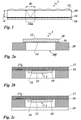
- FIG. 1 shows a multi-layer body 1 designed as a film, which has a carrier layer 10 in whose upper side microlenses 12 are molded.
- the microlenses 12 are spherical lenses which are distributed in a regular two-dimensional arrangement on the upper side of the carrier layer 10 .
- the microlenses 12 are arranged in dense packing, ie adjacent microlenses touch one another or are at a distance which is negligible in relation to their diameter. In the case of diameters of a few 10 ⁇ m, however, the distance, which is in the order of a few ⁇ m, is no longer negligible.
- the diameter D of the microlenses 12 is selected in the range from 10 ⁇ m to 50 ⁇ m.
- the underside of the carrier layer 10 is provided with a metallic layer 14 that has been removed in some areas and is covered by an adhesive layer 16 .
- Micropatterns 14m are molded into the metallic layer 14, with each micropattern 14m being assigned a microlens.
- the micro-patterns 14m are made of areas where the metallic layer 14 is preserved and formed from areas where the metallic layer is removed. The areas provided with the metallic layer appear as opaque portions and the areas where the metallic layer is removed appear as transparent portions.
- the transparent partial areas form a pictorial representation, for example a geometric figure and/or one or more alphanumeric characters and/or a logo and/or a partial area of a hologram or a KINEGRAM® .
- the opaque sections form a background from which the pictorial representation stands out.
- the proportion of the area of the opaque first partial areas to the total area of the first and second partial areas can be between 20% and 60%.
- the enlarged image of the micropattern or the imaged partial area of the micropattern created by the microlens 12 is in infinity, ie it can be viewed by an unaccommodated eye.
- the micropattern 14m must be in the focal plane of the microlens 12. Therefore, the thickness d of the support layer 10 is selected to be approximately equal to the focal length of the microlens 12.
- the optically effective thickness d of the carrier layer 10 measured from the flat side of the microlenses to the underside of the carrier film 10 (see 1 ), can range from 10 ⁇ m to 1000 ⁇ m. For window banknotes or the like, a range of 15 ⁇ m to 50 ⁇ m may be preferred. Depending on the configuration of the microlenses, the total thickness of the carrier layer can be greater than the optically effective thickness d by the amount of the lens thickness.
- the carrier layer 10 can be formed from a PET film, PEN film or the like or a similar thermoplastic material into which the microlenses are embossed by thermal molding. However, it can also be a PET film that is coated with a UV-curable lacquer or a UV-curable lacquer layer that is cured after molding.
- a particularly simple alignment of the micropatterns 14m in register can be achieved if the metallic layer 14 is formed with such a thickness that a photoresist layer applied to the metallic layer 14 can be exposed through the metallic layer, with the imaging of the micropatterns 14m through takes place through the microlenses 12.
- the carrier layer 10 is provided on its underside with a surface structure which, depending on the depth-to-width ratio of the surface structure in the metallic layer 14 then applied by sputtering or the like, areas with different transparency, ie formed with different thickness.
- the metallic layer 14 can also be used as an exposure mask for the photoresist.
- the dimensionless depth-to-width ratio is a characteristic feature for the surface enlargement of preferably periodic structures.
- Such a structure forms “mountains” and “valleys” in a periodic sequence.
- Depth is the distance between "mountain” and “valley”
- width is the distance between two "mountains”.
- This effect can also be observed when dealing with discretely distributed "valleys” which can be arranged at a distance from one another which is many times greater than the depth of the "valleys".
- the depth of the "valley” should be related to the width of the "valley” in order to accurately describe the geometry of the "valley” by specifying the depth-to-width ratio.
- the Figures 2a to 2c now show examples of the arrangement of the multi-layer body 1 on a carrier 20 formed with a window 20f, which can be a window bank note, for example.
- FIG. 12 shows a first example of an arrangement in which the multi-layer body 1 is applied to the window 20f with the aid of the adhesive layer 16.
- FIG. It's about the Figures 2a to 2c to schematic representations. It is possible, for example, for the paper carrier 20 to be pressed together in the area of the window 20f when the multi-layer body 1 is applied so that the surface of the carrier layer 10 is arranged flush with the surface of the carrier 10 .
- FIG. 12 shows a second arrangement example in which the multi-layer body 1 is arranged in the window 20f, with the microlenses 12 pointing to the back of the carrier 20.
- Adhesive layer 16 overlaps window 20f with the back of backing layer 10 flush with the front of backing 20.
- FIG. The microlenses 12 of the multilayer body 1 have therefore to the back of the carrier 20.
- the adhesive layer 16 is covered on its back by a first protective layer 17, wherein in the in Figure 2b illustrated embodiment, an optically active layer 17o is formed between the protective layer 17 and the adhesive layer 16 in an area arranged next to the window 20f, which layer can be, for example, a hologram or a ClNEGRAM® .
- FIG. 12 now shows a third example arrangement in which the multi-layer body 1 is completely encapsulated by the rear side of the window 20f being covered by a second protective layer 19.
- FIG. This can be a thermoplastic adhesive, but an adhesive layer can also be provided between the protective layer 19 and the back of the carrier 20 .
- the fully encapsulated multi-layer body 1 is particularly well protected against damage and/or soiling and can therefore preferably be provided for window banknotes.
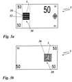
- a bank note 3 has a window 30 into which the multi-layer body 1 is introduced. Provision can also be made for the banknote to have a number of windows.
- the multi-layer body 1 can, for example, be a section of a foil strip 32, the edges of which Figure 3a are indicated by broken dashed lines, the foil strip 32 being positioned in such a way that the multi-layer body 1 completely fills the window 300 of the bank note 3 .
- the micropatterns are designed so that a number of euro currency symbols 34 are visible when the banknote 3 is viewed from the front.
- the euro currency symbols 34 appear to a viewer to float above, below or within the surface of the banknote and change position relative to the surface of the banknote 3 as the viewing angle changes.
- the euro currency symbols 34 appear transparent to the viewer's eye ( Figure 3a ), an effect that is contradictory when the window is viewed from the back of the note ( Figure 3b ).
- the observer sees in the window 30 of the banknote 3 a greyscale image 36 which is formed from the micropatterns 14m which cannot be resolved by the naked human eye.
- the pixels of the gray scale image 36 are formed from two different micropatterns 14m which are arranged in a grid, for example in a 50%/50% grid.
- the multi-layer body 1 arranged in the window 30 of the bank note 3 creates an interesting optical effect that is easy to imprint and allows a real bank note to be distinguished from a copied bank note at first glance.
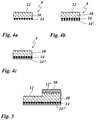
- the Figures 4a to 4c now show embodiment variants of the metallic layer 14 designed as a microimage layer.
- Figure 4a shows a multi-layer body 4, which is formed from the carrier layer 10, which has the microlenses 12 on its front side, and from the metallic layer 14, which is applied to the rear side of the carrier layer 10.
- the layer 14 can be made of gold, for example.
- FIG. 4 now shows a multi-layer body 4′ in which a further metallic layer 14′ is applied to the metallic layer 14, with both layers having the same structure. In this way, each area of a micropattern is formed of two superimposed layers 14 and 14'.
- the second layer can be silver, for example.
- the micro-patterns visible from the front appear in a golden setting, while the greyscale image visible from the back is silver.
- Figure 4c shows a multi-layer body 4", in which the layer 14 is covered with a layer 14", which also fills the areas in which the layer 14 has been partially removed.
- the layer 14" can be a metallic layer, but it can also be provided that the layer 14" is in the form of a color layer and is printed on. It can also be provided that the layer 14" is designed as a layer that is transparent in a spectral range, so that other interesting optical effects can be achieved.
- the figure 5 now shows a multi-layer body 5 which is constructed like the multi-layer body 4", but a section of the carrier layer 10 is covered with a protective layer 50.
- the carrier layer 14" has the focal length of which can differ from the microlenses 12 .
- the protective layer 50 and the carrier layer 10 differ in their refractive indices, so that the effect of the microlenses 12 is retained.
- the thickness of the support layer must be adjusted so that the layer 14 is again placed in the focal plane of the microlenses 12'.
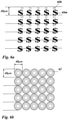
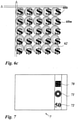
- FIGS. 6a to 6c show the effect of the individual layers of a multi-layer body according to the invention 6.
- Figure 6a shows micropatterns 60m, which are arranged in a square grid with a grid width of 40 ⁇ m.
- the micro-patterns 60m have a transparent dollar symbol as a pictorial representation, which for ease of representation is Figure 6a and 6c is shown blacked out.
- Captured image areas 60b are arranged to include different areas of the micropatterns 60m, respectively.
- the microlenses 62 shown are arranged in a square grid with a grid width of 40 ⁇ m. As in Figure 6c recognizable, both grids are around offset against each other by an amount ⁇ .
- micropattern grid is larger than the microlens grid ( ⁇ >0) or the micropattern grid is smaller than the microlens grid ( ⁇ 0).
- the alignment of the micropatterns can be provided differently.
- the micropatterns can have the same orientation as the enlarged images, ie aligned parallel to them; they can be upside down, ie aligned antiparallel to one another, and they can be arranged at an angle to one another, with an angle of about 90° being preferred.
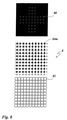
- the window banknote 7 shows the front view of a second window banknote 7, with the multilayer body 6 in the window 70 of the banknote 7 in Figures 6a to 6c is arranged.
- the window banknote 7 also has a KlNEGRAM® (71) and an embossed value (72).
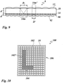
- microholes 80 form a pattern congruent to micropatterns 84m.
- a greater depth of field is achieved with the imaging of the micropattern 84m, the luminous intensity of the imaging decreases. Therefore, a layer with microlenses 82 is provided, which focus the light falling through the microholes 80 .
- Microlenses 82 and microholes 80 are associated 1:1 with one another and are exactly in register with one another.
- the microholes 80 form a "Swiss cross" with the dimensions 10 mm x 10 mm.
- the microlens array has the same dimensions of 10 mm x 10 mm. The effect of the microhole array is that it is seen accurately when the light collected by the microlenses is projected through the microholes 80 into the field of view.
- microhole fields next to one another in the register, which are illuminated at two angles by the microlens field, for example with laser light. In this way, a three-dimensional image of an object can be generated very easily using a complex of microhole fields.
- a microlens layer 90 is arranged on the side of the metallic layer 14 facing away from the carrier layer 10, in which microlenses 92 are molded on the outside.
- the microlenses 92 are spherical or aspherical lenses that are distributed on the outside of the microlens layer 90 in a regular two-dimensional array.
- the microlenses 92 are arranged in dense packing, ie adjacent microlenses touch one another or are at a distance that is negligible in relation to their diameter, provided their diameter is large compared to the usual distance of a few ⁇ m.
- the microlenses 92 have a diameter D′ which is smaller than the diameter D of the microlenses 12 formed on the carrier layer 10 .
- the focal length of the microlenses 92 is also smaller than the focal length of the microlenses 12, which is why the thickness d' of the microlens layer 90 is also smaller than the thickness of the carrier layer 10. Due to the different parameters of the microlenses 12 and 92, in particular the focal length and the diameter, a different visual impression is formed by the carrier layer 10 and the microlens layer 90, respectively. An observer now sees transparently appearing, differently enlarged images of different areas of the metallic layer 14, which appear to be floating at different heights above the multi-layer body and which change their position when the viewing angle changes.
- micropatterns 14m and 14m' which are each assigned to the microlenses 12 and 92, respectively.
- the micro-patterns 14m and 14m' are arranged in a 50%/50% grid.
- FIG. 10 shows a plan view of a non-claimed multi-layer body 100, the layer structure of which is that of the multi-layer body 1 in 1 is equivalent to.
- Molded into the outer surface of the carrier layer 10 are microlenses 102 and 102' of different diameters.
- the microlenses 102' have a smaller diameter than the microlenses 102.
- the diameter of the microlenses 102 is twice the diameter of the microlenses 102'.
- the microlenses 102' form a coherent L-shaped pattern area 104, the microlenses 102 form a rectangular background area 106.
- both microlens areas form a different optical impression, for example the illusion of image information floating at different heights.
- the microlenses 102 and 102' have the same focal length.
- the thickness d of the support layer 10 is constant and the vertices of the microlenses 102' are at a lower level than the vertices of the microlenses 102, the microlenses 102 and 102' being formed with a similar radius of curvature.
- the microlenses 102 can they are, for example, spherical caps whose plane surface is delimited by a great circle, and the microlenses 102' can be spherical caps whose plane surface is delimited by a small circle, the microlenses 102' consequently having a smaller thickness than the microlenses 102.
- the microlenses 102 and 102' can also be designed with different radiuses of curvature, so that the focal lengths of the two microlenses are different.
- the thickness d of the carrier layer 10 is designed differently in the above two areas, so that both in the background area 106, which is covered by the microlenses 102, and in the pattern area 104, which is covered by the microlenses 102 ' covered in the metallic layer 14 (in 10 not shown) formed micropatterns are respectively arranged in the focal plane of the microlenses 102, 102'.
- the L-shaped area formed by the microlenses 102' can also be detected tactilely. Such a property makes imitation considerably more difficult and also enables visually impaired people to check the authenticity.
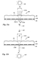
- FIG. 11a and 11b now show a non-claimed multi-layer body, 110, which is essentially like that above in 1 multi-layer body 1 shown is formed, but instead of the metallic layer 14 removed in certain areas, a metallic layer 114 provided with microholes 114l is provided. The microholes 114l are arranged at the focal point of the microlenses 12.
- FIG. The multi-layer body 110 is in Figure 11a illuminated by a light source 112 from the front. An observer 111 symbolized by an eye looks at the back of the multi-layer body 110.
- Figure 11b shows the multi-layer body 110 when illuminated from the rear; the viewer 111 is now looking at the front side of the multi-layer body 110.
- the microlenses 12 collect light rays incident from the front side of the multilayer body 110 of a beam 112v having the diameter D′ emanating from the light source 112 and concentrate them on the microholes 114l.
- the microholes 114l which have a diameter d' ⁇ D', appear to be enlarged by the bundles of rays 112v fanning out behind them, so that the totality of the microholes 114l gives the viewer 111 the optical impression of a luminous transparent surface.
- Figure 11b pass from the back of the multi-layer body 110 through the microholes 114l beams 112r with the diameter d 'through and due to the optical effect of the micro lenses 12 on the front of the multi-layer body 110 have the diameter D'>d'. Due to the enlargement of the bundles of rays 112r, their luminance falls, so that the multi-layer body appears as a light-shielding filter to the observer 111 who looks at its front side.
- the multi-layer body 110 is therefore a direction-dependent filter that can be applied to window panes, for example, as privacy protection.
Description
Die Erfindung betrifft einen Mehrschichtkörper mit einer Mikrolinsen-Anordnung, der vorzugsweise als optisches Sicherheitselement verwendbar ist.The invention relates to a multi-layer body with a microlens arrangement, which can preferably be used as an optical security element.
Optische Sicherheitselemente finden Anwendung in Fensterbanknoten, ID-Karten, Reisepässen und ähnlichen Sicherheitsdokumenten, um die Echtheit dieser Dokumente mit einfachen Mitteln überprüfen zu können und die Fälschung der Dokumente zu erschweren.Optical security elements are used in window banknotes, ID cards, passports and similar security documents in order to be able to check the authenticity of these documents with simple means and to make the forgery of the documents more difficult.
Es sind Lösungen für optische Sicherheitselemente bekannt, die Mikrolinsen zur Erzeugung optischer Effekte vorsehen.Solutions for optical security elements are known which provide microlenses for generating optical effects.
In
In
In
In
Der Erfindung liegt nun die Aufgabe zugrunde, einen Mehrschichtkörper zu schaffen, der als optisches Sicherheitselement verwendbar ist, das kostengünstig herstellbar ist und optische Effekte zeigt, die für jedermann leicht erkennbar und zugleich verblüffend oder überraschend und deshalb leicht einprägsam sind.In
In
In
The object of the invention is now to create a multi-layer body that can be used as an optical security element, that can be produced inexpensively and has optical effects that are easily recognizable and at the same time amazing or surprising and therefore easy to remember.
Die Aufgabe der Erfindung wird mit den in Anspruch 1 definierten Merkmalen gelöst.The object of the invention is achieved with the features defined in
Der erfindungsgemäße Mehrschichtkörper weist also erste Teilbereiche auf, in denen zumindest die zweite Schicht opak ausgebildet ist; und er weist zweite Teilbereiche auf, in denen alle Schichten des Mehrschichtkörpers transparent ausgebildet sind. Im Bereich der zweiten Teilbereiche ist der Mehrschichtkörper durchgehend transparent, d.h., die Schichten des Mehrschichtkörpers sind im Bereich der zweiten Teilbereiche transparent ausgebildet.
Ein solcher Mehrschichtkörper bildet bei der Betrachtung von der Vorderseite her und von der Rückseite her sehr unterschiedliche optische Effekte aus, die ein schwer nachahmbares Sicherheitsmerkmal bilden. Die in einer der ersten Schichten ausgeformten Mikrolinsen bilden ein optisches Abbildungssystem, das zur Vergrößerung der Mikromuster geeignet ist. Durch die Mikrolinsen wird jeweils ein Bildpunkt des Mikromusters pro Mikrolinse selektiert. Durch die Mikrolinsen geschieht dies sehr lichtstark, prinzipiell würde eine Lochmaske aber auch funktionieren. Das Mikromuster besteht aus ersten Teilbereichen, die für den menschlichen Betrachter bzw. das menschliche Auge opak, also lichtundurchlässig (durch Absorption oder Reflexion des einfallenden Lichtes) erscheinen und zweiten Teilbereichen, die für den menschlichen Betrachter bzw. das menschliche Auge transparent, also lichtdurchlässig erscheinen. Der auf diese Weise erzeugte Gesamteindruck zeigt transparente Bildbereiche, die in Abhängigkeit von der Blickrichtung ihre Lage wechseln, so daß es scheinen kann, daß ein transparenter Bildbereich vor einem opaken Hintergrund schwebt. Bilder können scheinbar hinter der Oberfläche des Mehrschichtkörpers erscheinen oder vor oder in dessen Oberfläche, abhängig davon, ob die Rasterweite der Mikrolinsen kleiner oder größer als die Rasterweite der Mikrobilder ist. Wenn die beiden Rasterweiten exakt gleich sind, jedoch etwas gegeneinander verdreht sind, ist der interessante Effekt zu beobachten, daß sich Bilder von links nach rechts zu bewegen scheinen, wenn der Mehrschichtkörper etwas zurück und vor bewegt wird und Bilder sich vor und zurück zu bewegen scheinen, wenn der Mehrschichtkörper nach links und rechts bewegt wird.The multi-layer body according to the invention therefore has first partial regions in which at least the second layer is opaque; and it has second partial regions in which all layers of the multi-layer body are transparent. In the area of the second partial areas, the multi-layer body is continuously transparent, ie the layers of the multi-layer body are transparent in the area of the second partial areas.
When viewed from the front and from the rear, such a multi-layer body forms very different optical effects, which form a security feature that is difficult to imitate. The microlenses formed in one of the first layers form an imaging optical system suitable for enlarging the micropatterns. One pixel of the micropattern per microlens is selected by the microlenses. Due to the microlenses, this happens very brightly, but in principle a shadow mask would also work. The micropattern consists of first partial areas that appear opaque to the human observer or the human eye, i.e. impermeable to light (due to absorption or reflection of the incident light) and second partial areas that appear transparent to the human observer or the human eye, i.e. translucent . The overall impression created in this way shows transparent image areas that change their position depending on the viewing direction, so that it can appear that a transparent image area is floating in front of an opaque background. Images may appear to appear behind the surface of the multilayer body, or in front of or within its surface, depending on whether the microlens pitch is smaller or larger than the microimage pitch. If the two screen rulings are exactly the same but are slightly skewed from each other, the interesting effect is observed that when the composite is moved back and forth slightly, images appear to move from left to right and images appear to move back and forth , when the laminated body is moved left and right.
Es ist weiter möglich, daß Bilder seitenverkehrt bzw. gedreht dargestellt werden, d.h. die Bilder können vergrößerte Versionen der Mikromuster sein (Vergrößerung > 1) oder die Bilder können seitenverkehrte bzw. gedrehte Versionen der Mikromuster sein (Vergrößerung < -1).It is also possible for images to be reversed or rotated, i.e. the images can be enlarged versions of the micropatterns (magnification >1) or the images can be reversed or rotated versions of the micropatterns (magnification <-1).
Bei der Betrachtung von der Rückseite her erscheint der Mehrschichtkörper dagegen als opake Fläche, die beispielsweise eine Information in Art eines Graustufenbildes zeigen kann. Dieser scheinbare Widerspruch zwischen den beiden optischen Eindrücken zeigt sich sowohl im Auflicht als auch im Durchlicht und ist sehr auffällig und einprägsam.On the other hand, when viewed from the rear, the multi-layer body appears as an opaque surface which can show information in the form of a grayscale image, for example. This apparent contradiction between the two optical impressions can be seen in reflected light as well as in transmitted light and is very noticeable and memorable.
Unvermeidliche Fertigungstoleranzen bezüglich des Radius der Mikrolinsen, der Brechzahl und der Dicke der Mikrolinsenschicht beeinträchtigen die Funktionsfähigkeit des erfindungsgemäßen Mehrschichtkörpers nicht. Wie Versuche ergeben haben, kann die Dicke der Mikrolinsenschicht zwischen 10% bis 20% der Brennweite vom Sollwert abweichen.Unavoidable manufacturing tolerances regarding the radius of the microlenses, the refractive index and the The thickness of the microlens layer does not impair the functionality of the multilayer body according to the invention. Tests have shown that the thickness of the microlens layer can deviate from the target value by between 10% and 20% of the focal length.
Vorteilhafte Ausgestaltungen der Erfindung sind in den Unteransprüchen bezeichnet.Advantageous configurations of the invention are specified in the dependent claims.
Es kann vorgesehen sein, daß die transparenten zweiten Teilbereiche eine bildliche Darstellung bilden, und daß die opaken ersten Teilbereiche einen Hintergrundbereich bilden, von dem sich die bildliche Darstellung abhebt. Hierdurch ergeben sich weitere interessante Effekte. Es kann beispielsweise der Eindruck entstehen, durch ein Schlüsselloch zu schauen und dabei auf eine leuchtende Fläche zu blicken. Dieser Schlüssellocheffekt ist unerwartet, weil der Betrachter auf eine scheinbar durchgängig opake Fläche blickt, wenn er einen anderen Betrachtungswinkel wählt oder den Mehrschichtkörper von der anderen Seite betrachtet.Provision can be made for the transparent second partial areas to form a pictorial representation and for the opaque first partial areas to form a background area from which the pictorial representation stands out. This results in further interesting effects. For example, the impression can arise of looking through a keyhole and looking at a luminous surface. This keyhole effect is unexpected because the viewer is looking at what appears to be a consistently opaque surface if he selects a different viewing angle or looks at the multi-layer body from the other side.
Weiter kann vorgesehen sein, daß der Flächenanteil der opaken ersten Teilbereiche zur Gesamtfläche der ersten und zweiten Teilbereiche 20% bis 60% ist. In diesem Bereich ist der oben beschriebene Effekt besonders signifikant ausgeprägt. Je höher der Flächenanteil der opaken Teilbereiche an der Gesamtfläche ist, desto kleiner sind die den Schlüssellocheffekt bildenden transparenten Bildbereiche und umgekehrt.Furthermore, it can be provided that the area proportion of the opaque first sub-areas to the total area of the first and second sub-areas is 20% to 60%. The effect described above is particularly pronounced in this area. The higher the proportion of the area of the opaque partial areas in the total area, the smaller are the transparent image areas forming the keyhole effect and vice versa.
Es kann vorgesehen sein, daß es sich bei der bildlichen Darstellung um eine geometrische Figur, um ein oder mehrere alphanumerisches Zeichen oder um ein Logo handelt. Wenn der erfindungsgemäße Mehrschichtkörper als Sicherheitselement in einer mit einem Fenster ausgebildeten Banknote eingesetzt wird, kann es sich bei dem Mikromuster um ein Währungssymbol handeln, beispielsweise um ein Euro- oder Dollar-Zeichen. Durch die Kombination der vorstehend genannten Ausbildungen der Mikromuster mit dem Hintergrundbereich können weitere interessante optische Effekte ausgebildet werden. So kann beispielsweise ein alphanumerisches Zeichen vor einem holographischen Hintergrund dargestellt werden, d.h. der erste opake Teilbereich kann als Hologramm oder KINEGRAM® ausgebildet sein. Beispielsweise kann ein holografischer Hintergrundbereich durch das vorstehend genannte Euro- oder Dollar-Zeichen perforiert erscheinen, die wiederum wie ein Schlüsselloch den Blick auf eine transparente leuchtende Fläche lenken. Dabei kann das Euro- oder Dollar-Zeichen beim Ändern der Betrachtungsrichtung scheinbar über das Hologramm wandern. Das Hologramm oder KINEGRAM® kann in seiner Qualität durch die Mikrolinsen etwas eingeschränkt sein, wobei die Mikrolinsen für das Hologramm oder KINEGRAM® nicht vergrößernd wirken.The pictorial representation may be a geometric figure, one or more alphanumeric characters, or a logo. If the multi-layer body according to the invention is used as a security element in a banknote provided with a window, the micropattern can be a currency symbol, for example a euro or dollar sign. Further interesting optical effects can be formed by combining the above-mentioned configurations of the micropatterns with the background area. For example, an alphanumeric character can be displayed in front of a holographic background, ie the first opaque partial area can be in the form of a hologram or KINEGRAM® . For example, a holographic background area may appear perforated by the euro or dollar sign mentioned above, which in turn, act like a keyhole, drawing the eye to a transparent luminous surface. The euro or dollar sign can appear to move across the hologram when you change the viewing direction. The quality of the hologram or KINEGRAM ® may be limited somewhat by the microlenses, although the microlenses do not magnify the hologram or KINEGRAM ® .
Die Mikrolinsen können beispielsweise durch Heißprägen in eine thermoplastische Folie oder durch Prägen und Aushärten einer UV-härtbaren Schicht geformt werden. Diese Herstellungsverfahren sind aus der Herstellung von mehrschichtigen Übertragungsfolien bekannt. Die Mikrolinsen können auch durch Intagliodruck erzeugt werden, wobei durch unterschiedliche Brechzahlen der Mikrolinsen und des Trägermaterials u.U. ein Helligkeitsverlust eintreten kann infolge von Totalbrechung an der Grenzfläche für große Bildwinkel. Die Mikrolinsen können auch durch Aufschmelzen von abgetrennten Oberflächenbereichen gebildet werden, wobei die aufgeschmolzenen Oberflächenbereiche infolge der Oberflächenspannung eine Kugelform einnehmen. Es ist auch möglich, asphärische Linsen auszuformen, die beträchtliche Vorteile bezügliche der Tiefenschärfe und dem Abbildungswinkel haben können. Asphärische Linsen können erzeugt werden mit der sog. Reflow-Methode in Kombination mit reaktivem lonenätzen oder Graustufen-Technologien (z.B. HEBS-Glas oder Erzeugung mit Elektronenstrahl). Weiter ist es möglich, daß die Mikrolinsen als diffraktive Mikrolinsen (gegen Luft oder eingebettet in weiteren Materialschichten), als diffraktive Linsen (d.h. als entsprechendes Präge- oder Volumenhologramm) oder realisiert als Gradienten-Index in einer optisch transparenten Schicht realisiert sind.The microlenses can be formed, for example, by hot embossing into a thermoplastic film or by embossing and curing a UV-curable layer. These production processes are known from the production of multi-layer transfer foils. The microlenses can also be produced by intaglio printing, whereby the different refractive indices of the microlenses and the carrier material can sometimes result in a loss of brightness as a result of total refraction at the interface for large image angles. The microlenses can also be formed by melting separated surface areas, the melted surface areas assuming a spherical shape as a result of surface tension. It is also possible to design aspherical lenses, which can have significant advantages in terms of depth of focus and angle of view. Aspheric lenses can be created using the so-called reflow method in combination with reactive ion etching or greyscale technologies (e.g. HEBS glass or production with electron beam). It is also possible for the microlenses to be implemented as diffractive microlenses (against air or embedded in further material layers), as diffractive lenses (i.e. as a corresponding embossed or volume hologram) or implemented as a gradient index in an optically transparent layer.
Wie oben beschrieben ist vorgesehen, daß die Mikromuster Bildpunkte eines Graustufenbildes bilden, wobei die Abmessungen der Bildpunkte < 300 µm sind. Bei dem Graustufenbild handelt es sich um ein Bild, dessen Bildpunkte sich durch ihren Grauwert unterscheiden.
Der Grauwert kann im allgemeinen als Helligkeitswert einer Farbfläche verstanden sein. Die Grundfarbe eines Graustufenbildes muß deshalb nicht Grau sein. Ein Graustufenbild kann auch eingefärbt sein, wie beispielsweise von sepiagetönten Schwarzweiß-Fotos bekannt. Die Farbe des Graustufenbildes kann auch durch die Farbe des für den Aufbau der Mikromuster vorgesehenen Materials bestimmt sein, zum Beispiel kann das Graustufenbild bei Verwendung von Gold goldfarben erscheinen oder bei einer Druckfarbe deren Farbton aufweisen. Weiter kann vorgesehen sein, daß das Mikromuster aus zwei Schichten aufgebaut ist, die einen unterschiedlichen Farbeindruck hervorrufen, so daß bei Betrachtung der Vorderseite ein anderer Farbeindruck ausgebildet ist als bei Betrachtung der Rückseite. Es kann auch vorgesehen sein, eine der Schichten vollflächig aufzubringen und für einen begrenzten Spektralbereich transparent auszubilden. Es kann sich bei den Bildpunkten auch um in verschiedenen Farben irisierende Bildpunkte handeln. Wie weiter oben beschrieben, können die Mikromuster unterschiedliche Grauwerte aufweisen, die eine Graustufenskala bilden.As described above, it is provided that the micropatterns form pixels of a gray scale image, the dimensions of the pixels being <300 μm. The grayscale image is an image whose pixels differ in terms of their gray value.
The gray value can generally be understood as the brightness value of a color area. The basic color of a grayscale image therefore does not have to be gray. A grayscale image can also be colored, as is known from sepia-toned black-and-white photos, for example. The color of the greyscale image can also be determined by the color of the material provided for the construction of the micropatterns, for example the greyscale image can appear gold-colored if gold is used or have the hue of gold if an ink is used. It can further be provided that the micropattern is made up of two layers which produce a different color impression, so that when the front side is viewed a different color impression is formed than when the back side is viewed. Provision can also be made to apply one of the layers over the entire surface and to make it transparent for a limited spectral range. The pixels can also be iridescent pixels in different colors. As described above, the micro-patterns can have different gray values that form a gray scale.
Es kann vorgesehen sein, daß Mikromuster einen unterschiedlichen Grauwert aufweisen, indem die Opazität der ersten Teilbereiche und/oder die Transparenz der zweiten Teilbereiche variiert ist. Die Bildpunkte weisen demnach ein unterschiedliches Reflexionsvermögen auf (wenn Betrachtung im Auflicht vorgesehen ist) oder eine unterschiedliche Opazität auf (wenn Betrachtung im Durchlicht vorgesehen ist). Die Opazität ist ein Maß für die Lichtundurchlässigkeit von Stoffen. Das Gegenteil der Opazität ist die Transparenz, die ein Maß für die Lichtdurchlässigkeit von Stoffen ist. Opazität und Transparenz sind auf die optische Dichte oder Extinktion zurückzuführen, die ein Maß für die Abschwächung einer Strahlung, zum Beispiel Licht, in einem Medium ist. Der Anteil der durchgelassenen Strahlung wird als Transmissionsgrad bezeichnet. Die optische Dichte ist der negative dekadische Logarithmus des Transmissionsgrades. Die Einteilung in opake erste Teilbereiche und transparente zweite Teilbereiche ist bezüglich dieser Ausführungsform der Erfindung so, daß die opaken ersten Teilbereiche deutlich weniger transparent sind als die transparenten zweiten Teilbereiche und insbesondere durch einen menschlichen Beobachter opake und transparente Teilbereiche als solche erkennbar und deutlich voneinander unterscheidbar sind.Provision can be made for micropatterns to have a different gray value by varying the opacity of the first partial areas and/or the transparency of the second partial areas. The pixels accordingly have a different reflectivity (if viewing in incident light is intended) or a different opacity (if viewing in transmitted light is intended). Opacity is a measure of the opacity of materials. The opposite of opacity is transparency, which is a measure for the translucency of materials. Opacity and transparency are due to optical density or absorbance, which is a measure of the attenuation of radiation, such as light, in a medium. The proportion of transmitted radiation is referred to as transmittance. Optical density is the negative logarithm of the transmittance. With regard to this embodiment of the invention, the division into opaque first partial areas and transparent second partial areas is such that the opaque first partial areas are significantly less transparent than the transparent second partial areas and in particular by a human observer opaque and transparent partial areas are recognizable as such and clearly distinguishable from one another .
Durch die weiter oben beschriebene bildpunktweise Vergrößerung der Bildpunkte der Mikromuster erscheint das vergrößerte Mikromuster trotz Variation des Grauwertes der Mikromuster im allgemeinen mit homogenem Grauwert. Es ist jedoch auch möglich, das von der Rückseite des erfindungsgemäßen Mehrschichtkörpers sichtbare Graustufenbild so auszubilden, daß sich bei der Betrachtung des von der Vorderseite des Mehrschichtkörpers her sichtbaren vergrößerten Abbildes ein weiterer interessanter optischer Effekt einstellt, beispielsweise daß die vergrößerte bildliche Darstellung einen Transparenzverlauf aufweist und/oder daß der opake Hintergrundbereich einen Opazitätsverlauf aufweist. Es ist also möglich, Bildpunkte mit unterschiedlichen Grauwerten für ein Graustufenbild bereitzustellen, das von der den Mikrolinsen abgewandten Seite der zweiten Schicht her sichtbar ist.As a result of the pixel-by-pixel enlargement of the pixels of the micro-pattern described above, the enlarged micro-pattern generally appears with a homogeneous gray value despite the variation in the gray value of the micro-pattern. However, it is also possible to form the greyscale image visible from the back of the multi-layer body according to the invention in such a way that when the enlarged image visible from the front of the multi-layer body is viewed, another interesting optical effect occurs, for example that the enlarged pictorial representation has a transparency gradient and /or that the opaque background area has an opacity gradient. It is thus possible to provide image points with different gray values for a gray scale image which is visible from the side of the second layer which is remote from the microlenses.
Das unbewaffnete Auge ist nicht in der Lage, die oben beschriebenen Bildpunkte der Abmessungen < 300 µm als ein Mikromuster zu erkennen. Es kann sogar nicht in der Lage sein, die aus Mikromustern gebildeten Bildpunkte als getrennte Bildpunkte aufzulösen, so daß es das Graustufenbild nur in seiner Gesamtheit wahrnimmt.The naked eye is not able to recognize the above-described pixels with dimensions < 300 µm as a micro-pattern. It may even be unable to resolve the micropatterned pixels as separate pixels, so it only sees the grayscale image as a whole.
In einer weiteren vorteilhaften Ausgestaltung ist vorgesehen, daß die Mikrolinsen und die Mikromuster eine repetitive Anordnung aufweisen.
Bei dem Raster kann es sich um ein gitterförmiges Raster handeln mit orthogonalen Begrenzungslinien. Es kann sich aber auch um ein anderes Raster handeln, beispielsweise um ein hexagonales Raster. Das Raster kann auch mit schiefwinkligen Begrenzungslinien ausgebildet sein oder zu den Begrenzungskanten des Mehrschichtkörpers um einen Winkel gedreht sein.In a further advantageous embodiment it is provided that the microlenses and the micropatterns have a repetitive arrangement.
The grid can be a grid-like grid with orthogonal boundary lines. However, it can also be a different grid, for example a hexagonal grid. The grid can also be designed with oblique boundary lines or rotated at an angle to the boundary edges of the multilayer body.
Es kann vorgesehen sein, daß die Mikrolinsen und die Mikromuster jeweils in einem zweidimensionalen Raster angeordnet sind, wobei die Rasterweite insbesondere 20 µm bis 50 µm beträgt.It can be provided that the microlenses and the micropatterns are each arranged in a two-dimensional grid, the grid width being in particular 20 μm to 50 μm.
Es kann weiter vorgesehen sein, daß die Raster der Mikrolinsen und der Mikromuster übereinstimmen. Mikrolinsenraster und Mikromusterraster können auch gegeneinander verdreht sein (u.U. sehr wenig, wie zum Beispiel einige Zehntel Grad), vor allem für den Fall, daß die Rasterweiten identisch sind.Provision can also be made for the grid of the microlenses and the micropattern to match. Microlens rasters and micropattern rasters can also be rotated in relation to each other (possibly very little, such as a few tenths of a degree), especially if the raster widths are identical.
Alternativ kann vorgesehen sein, daß die Raster der Mikrolinsen und der Mikromuster verschieden sind. Es kann so beispielsweise ein Moire-Effekt erzeugt sein, der ein charakteristisches optisches Merkmal sein kann.Alternatively, it can be provided that the raster of the microlenses and the micropattern are different. In this way, for example, a moiré effect can be produced, which can be a characteristic optical feature.
In einerweiteren Ausgestaltung ist vorgesehen, daß die Rasterweite der Mikrolinsen und/oder der Mikromuster konstant ist. Bei konstanter Rasterweite sind Δx(x,y) und Δy(x,y) konstant (x,y: Koordinaten-Achsen der von der Oberfläche des Mehrschichtkörpers aufgespannten Ebene; Δx, Δy: Abstand der Mikromuster in x- bzw. y-Richtung voneinander). Es kann vorgesehen sein, daß das Mikrolinsen-Array und das Mikromuster-Array identische Raster aufweisen, die jedoch gegeneinander verdreht sind.In a further embodiment it is provided that the raster width of the microlenses and/or the micropattern is constant. With a constant grid width, Δx(x,y) and Δy(x,y) are constant (x,y: coordinate axes of the plane spanned by the surface of the multilayer body; Δx, Δy: spacing of the micropatterns in the x or y direction from each other). Provision can be made for the microlens array and the micropattern array to have identical grids which, however, are rotated in relation to one another.
Es kann aber auch vorgesehen sein, daß die Rasterweite der Mikrolinsen und/oder der Mikromuster variabel ist. Die Rasterweite kann dann von den Koordinaten eines Punktes abhängig sein, also ![]()
![]()
![]()
![]()
Eine variable Rasterweite kann beispielsweise den weiter oben genannten Moire-Effekt auslösen, sie kann aber auch dafür genutzt werden, um den Mikrolinsen die Bildpunkte der Mikromuster zuzuordnen und so gestalterischen Einfluß auf die Ausbildung des bzw. der vergrößerten Mikromuster zu nehmen. Die Rasterweite kann beispielsweise aufgrund einer speziell definierten mathematischen Funktion variieren.A variable raster width can, for example, trigger the Moiré effect mentioned above, but it can also be used to assign the pixels of the micropattern to the microlenses and thus have a creative influence on the formation of the enlarged micropattern(s). For example, the screen width can vary due to a specially defined mathematical function.
Es kann weiter vorgesehen sein, daß die Raster der Mikrolinsen und der Mikromuster zueinander versetzt sind.Provision can also be made for the grids of the microlenses and the micropatterns to be offset in relation to one another.
Die Mikromuster selber können sich auch ändern, beispielsweise können mehrere Mikromuster in Teilrastern angeordnet sein. Auf diese Weise kann beispielsweise eine spiralförmige Anordnung vorgesehen sein.The micro-patterns themselves can also change, for example several micro-patterns can be arranged in partial grids. In this way, for example, a spiral arrangement can be provided.
Es können mehrere unterschiedliche Mikromuster in geordneter Anordnung angeordnet sein, wodurch beispielsweise ein Stereo- oder Pseudostereo-Effekt ausgebildet werden kann. Es kann auch vorgesehen sein, bei unterschiedlichem Betrachtungswinkel unterschiedliche vergrößerte Mikromuster darzustellen, wodurch beispielsweise ein Bewegungseffekt oder ein Morphing-Effekt erzeugbar ist.A number of different micropatterns can be arranged in an ordered arrangement, as a result of which a stereo or pseudo-stereo effect can be formed, for example. Provision can also be made to display different enlarged micropatterns at different viewing angles, as a result of which a movement effect or a morphing effect can be generated, for example.
In einer weiteren vorteilhaften Ausgestaltung ist vorgesehen, daß die Mikrolinsen und die Mikromuster im Register angeordnet sind. Die Anordnung im Register ist zwar nicht zwingend für die Ausbildung der vorstehend beschriebenen optischen Effekte, doch werden auf diese Weise besonders gut reproduzierbare Ergebnisse erreicht. Nachahmungen, die beispielsweise durch Übereinanderfügen getrennt hergestellter Mikrolinsenarrays und Mikromusterarrays erzeugt werden, sind nur mit hohem Aufwand in gleichbleibender Qualität herstellbar. Die Anordnung im Register kann auch vorgesehen sein für nicht-repetitive Raster, beispielsweise für deformierte, transformierte oder verzerrte Raster.In a further advantageous embodiment it is provided that the micro-lenses and the micro-patterns are arranged in register. The arrangement in the register is not mandatory for the formation of the above described optical effects, but particularly well reproducible results are achieved in this way. Imitations, which are produced, for example, by superimposing separately produced microlens arrays and micropattern arrays, can only be produced with a great deal of effort and with consistent quality. The arrangement in the register can also be provided for non-repetitive rasters, for example for deformed, transformed or distorted rasters.
In einer nicht beanspruchten Ausgestaltung ist vorgesehen, daß die Mikromuster der zweiten Schicht jeweils von einem als Mikroloch ausgebildeten transparenten zweiten Teilbereich und von einem den zweiten Teilbereich vollständig umgebenden opaken ersten Teilbereich der zweiten Schicht gebildet sind..
Weiter ist vorgesehen, daß die Mikrolinsen und die Mikrolöcher eine repetitive Anordnung aufweisen. Vorteilhafterweise ist vorgesehen, daß die Mikrolinsen und die Mikrolöcher jeweils in einem zweidimensionalen Raster angeordnet sind. Vorzugsweise stimmen die beiden Raster überein, so daß zu jedem Mikroloch eine Mikrolinse zugeordnet ist. Die Mikrolöcher können zwar mit beliebiger Kontur ausgebildet sein, doch ist die mit der Mikrolinsenform korrespondierende kreisförmige Lochkontur bevorzugt.
Weiter kann vorgesehen sein, daß die Mikrolinsen und die Mikrolöcher im Register angeordnet sind, wobei die Brennpunkte der Mikrolinsen mit den Mittelpunkten der Mikrolöcher korrespondieren. Auf diese Weise ist also genau eine Mikrolinse über einem Mikroloch angeordnet, wobei sich das Mikroloch in der Brennebene der Mikrolinse befindet.
Es ist weiter vorgesehen, daß der Durchmesser der Mikrolinse größer als der Durchmesser des Mikrolochs ist. Auf diese Weise ist der erfindungsgemäße Mehrschichtkörper als ein richtungsabhängiges Filter ausgebildet. Wenn vor der Rückseite des Mehrschichtkörpers eine Lichtquelle angeordnet ist, wirken die Mikrolöcher als Blenden, die nur einen Teil der auf den Mehrschichtkörper auftreffenden Strahlen der Lichtquelle hindurchtreten lassen. Der Mehrschichtkörper kann also in einer solchen Anordnung beispielsweise als Sonnenschutz verwendet werden. Wenn jedoch vor der Vorderseite des Mehrschichtkörpers eine Lichtquelle angeordnet ist, bündeln die Mikrolinsen die Strahlen und leiten sie konzentriert durch die Mikrolöcher hindurch. Auf diese Weise werden nahezu alle auf den Mehrschichtkörper auftreffenden Strahlen hindurchgelassen, und die Rückseite des Mehrschichtkörpers erscheint als transparent leuchtende Fläche.In an embodiment that is not claimed, it is provided that the micropatterns of the second layer are each formed by a transparent second partial area designed as a microhole and by an opaque first partial area of the second layer that completely surrounds the second partial area.
It is further provided that the microlenses and the microholes have a repetitive arrangement. It is advantageously provided that the microlenses and the microholes are each arranged in a two-dimensional grid. The two grids preferably match, so that a microlens is assigned to each microhole. Although the microholes can be formed with any contour, the circular hole contour corresponding to the microlens shape is preferred.
It can further be provided that the microlenses and the microholes are arranged in register, with the focal points of the microlenses corresponding to the centers of the microholes. In this way, exactly one microlens is arranged over a microhole, with the microhole being located in the focal plane of the microlens.
It is further provided that the diameter of the microlens is larger than the diameter of the microhole. In this way, the multi-layer body according to the invention is designed as a direction-dependent filter. If a light source is arranged in front of the rear side of the multi-layer body, the microholes act as screens which only allow some of the rays of the light source impinging on the multi-layer body to pass through. In such an arrangement, the multi-layer body can therefore be used, for example, as sun protection. However, if a light source is arranged in front of the front side of the multi-layer body, the micro-lenses focus the rays and direct them through the micro-holes in a concentrated manner. In this way, almost all of the rays impinging on the multi-layer body are let through, and the rear side of the multi-layer body appears as a transparently luminous surface.
Es kann vorgesehen sein, daß der Durchmesser des Mikrolochs 1 % bis 50 % des Durchmessers der Mikrolinse beträgt.It can be provided that the diameter of the microhole is 1% to 50% of the diameter of the microlens.
Der vorstehend beschriebene Mehrschichtkörper kann beispielsweise als die Übertragungslage einer Transferfolie ausgebildet sein, die auf Fensterscheiben oder dergleichen aufbringbar ist. Die Folie kann auch auf um 180° schwenkbare Lamellen einer vor oder hinter einem Fenster angeordneten Sonnenschutzvorrichtung aufgebracht werden, die in den beiden Endstellungen eine durchgehende Fläche bilden. Die Sonnenschutzvorrichtung kann in der einen Stellung der Lamellen als hoch wirksamer Sonnenschutz und in der anderen Stellung der Lamellen als hoch lichtdurchlässiger Sichtschutz verwendet werden. In der 90°-Zwischenstellung kann sie den Blick durch die Fensterscheibe freigeben.The multi-layer body described above can be formed, for example, as the transfer layer of a transfer film that can be applied to window panes or the like. The film can also be applied to 180° pivotable slats of a sun protection device arranged in front of or behind a window, which form a continuous surface in the two end positions. The sun protection device can be used in one position of the slats as a highly effective sun protection and in the other position of the slats as a highly translucent privacy screen. In the 90° intermediate position, it can provide a view through the window pane.
Die Herstellung der feinen Strukturen der Mikromuster kann erleichtert sein, wenn vorgesehen ist, daß die zweite Schicht in den opaken ersten Teilbereichen und in den transparenten zweiten Teilbereichen eine Oberflächenstruktur mit unterschiedlichem Tiefen-zu-Breiten-Verhältnis aufweist. Die Dicke der zweiten Schicht kann mit Hilfe des Tiefen-zu-Breiten-Verhältnisses der Oberflächenstruktur der ersten Schicht eingestellt werden, auf die die zweite Schicht aufgebracht ist. Es kann vorgesehen sein, daß die zweite Schicht mit konstanter Flächendichte aufgebracht wird, beispielsweise durch Sputtern. Die effektive Dicke der zweiten Schicht ist dabei um so geringer, je höher das Tiefen-zu-Breiten-Verhältnis der besagten Oberflächenstruktur ist. Das dimensionslose Tiefen-zu-Breiten-Verhältnis, häufig auch als Aspektrate bezeichnet, ist ein kennzeichnendes Merkmal für die Oberflächenvergrößerung vorzugsweise periodischer Strukturen. Eine solche Struktur weist in periodischer Abfolge "Berge" und "Täler" auf. Als Tiefe ist hier der Abstand zwischen "Berg" und "Tal" bezeichnet, als Breite der Abstand zwischen zwei "Bergen". Je höher nun das Tiefen-zu-Breiten-Verhältnis ist, desto steiler sind die "Bergflanken" ausgebildet und desto dünner ist eine auf den "Bergflanken" abgeschiedene metallische Schicht ausgebildet. Dieser Effekt ist vergleichbar mit der Ablagerung von Schnee auf schrägen Dächern.The production of the fine structures of the micropatterns can be facilitated if it is provided that the second layer has a surface structure with a different depth-to-width ratio in the opaque first partial areas and in the transparent second partial areas. The thickness of the second layer can be adjusted using the depth-to-width ratio of the surface structure of the first layer to which the second layer is applied. Provision can be made for the second layer to be applied with a constant areal density, for example by sputtering. The effective thickness of the second layer is the smaller, the higher the depth-to-width ratio of said surface structure is. The dimensionless depth-to-width ratio, often also referred to as the aspect ratio, is a characteristic feature for the surface enlargement of preferably periodic structures. Such a structure has "mountains" and "valleys" in a periodic sequence. Depth is the distance between "mountain" and "valley", width is the distance between two "mountains". The higher the depth-to-width ratio, the steeper the "mountain flanks" are and the thinner a metallic layer deposited on the "mountain flanks" is formed. This effect is comparable to the deposition of snow on sloping roofs.
Weiter ist vorgesehen, daß die ersten Schichten und die zweite Schicht zusammen eine Dicke von 10 µm bis 1000 µm aufweisen.It is further provided that the first layers and the second layer together have a thickness of 10 μm to 1000 μm.
In einer weiteren Ausgestaltung ist vorgesehen, daß die ersten Schichten und die zweite Schicht zusammen eine Dicke von 15 µm bis 50 µm aufweisen. Kleine Schichtdicken machen den Mehrschichtkörper besonders geeignet zum Einbringen in Fenster von Papierträgern, die auf diese Weise flexibel bleiben.In a further embodiment it is provided that the first layers and the second layer together have a thickness of 15 μm to 50 μm. Small layer thicknesses make the multi-layer body particularly suitable for introducing into windows of paper carriers, which remain flexible in this way.
In einer weiteren vorteilhaften Ausgestaltung ist vorgesehen, daß die zweite Schicht auf der der ersten Schicht abgewandten Seite mit einer oder mehreren transparenten dritten Schichten versehen ist, die auf ihrer der zweiten Schicht abgewandten Oberfläche ein Oberflächenprofil aufweist, das eine Anordnung einer Vielzahl von zweiten Mikrolinsen bildet, und daß die Dicke dieser dritten Schicht oder dieser dritten Schicht und zwischen dieser dritten Schicht und der zweiten Schicht angeordneten ein oder mehreren weiteren dritten Schichten in etwa der Brennweite der zweiten Mikrolinsen entspricht. Die zweiten Linsen sind auf die Rückseite der Mikromuster gerichtet und können deshalb von den Mikromustern ein spiegelbildliches vergrößertes Abbild erzeugen.In a further advantageous embodiment, the second layer is provided with one or more transparent third layers on the side facing away from the first layer, which has a surface profile on its surface facing away from the second layer that forms an arrangement of a large number of second microlenses and that the thickness of this third layer or this third layer and one or more further third layers arranged between this third layer and the second layer corresponds approximately to the focal length of the second microlenses. The second lenses are aimed at the back of the micro-patterns and can therefore produce a mirror image enlarged image of the micro-patterns.
Es kann aber auch vorgesehen sein, daß die Mikromuster erste und zweite Mikromuster umfassen, wobei die ersten und die zweiten Mikromuster in Teilrastern angeordnet sind, die einen Raster bilden. Auf diese Weise können die zweiten Mikrolinsen ein vergrößertes Abbild erzeugen, bei dem es sich nicht um ein gespiegeltes von den ersten Mikrolinsen erzeugtes Abbild handelt.But it can also be provided that the Micro-patterns comprise first and second micro-patterns, the first and second micro-patterns being arranged in sub-grids forming a grid. In this way, the second microlenses can produce a magnified image that is not a mirrored image produced by the first microlenses.
Vorteilhafterweise kann vorgesehen sein, daß der Raster ein 50%/50%-Raster ist.Provision can advantageously be made for the grid to be a 50%/50% grid.
In einer weiteren Ausgestaltung ist vorgesehen, daß mindestens einige der Mikrolinsen eine unterschiedliche Farbe aufweisen. Wegen des geringen Durchmessers der Mikrolinsen kann vorgesehen sein, daß die eingefärbten Mikrolinsen einen Bereich mit solchen Abmessungen bilden, daß er mit unbewaffnetem Auge wahrnehmbar ist.In a further embodiment it is provided that at least some of the microlenses have a different color. Because of the small diameter of the microlenses, it can be provided that the colored microlenses form an area with such dimensions that it can be perceived with the naked eye.
Es kann vorgesehen sein, daß die Mikrolinsen ein farbliches Muster bilden.Provision can be made for the microlenses to form a colored pattern.
Ein weiterer interessanter optischer Effekt ist erzielbar, wenn vorgesehen ist, daß einander gegenüberliegend angeordnete Mikrolinsen der ersten und der dritten Schicht komplementär gefärbt ausgebildet sind. Auf diese Weise kann die Transparenz der vergrößerten Mikromuster aufgehoben werden, weil jeweils die beiden gegenüberliegenden Mikrolinsen alle Lichtfarben ausfiltern. Der Effekt kann auch nur für einen Kippwinkelbereich des Mehrschichtkörpers ausgebildet werden.A further interesting optical effect can be achieved if it is provided that microlenses of the first and the third layer arranged opposite one another are designed to be colored in a complementary manner. In this way, the transparency of the enlarged micro-patterns can be eliminated because the two opposing micro-lenses filter out all light colors. The effect can also only be formed for a range of tilting angles of the multi-layer body.
In einer weiteren nicht beanspruchten Ausgestaltung ist vorgesehen, daß die erste Schicht und/oder die dritte Schicht Mikrolinsen mit mindestens zwei unterschiedlichen Durchmessern aufweisen bzw. aufweist.
Es kann vorgesehen sein, daß Mikrolinsen mit gleichem Durchmesser einen Bereich bilden.
Weiter kann vorgesehen sein, daß der Bereich, den die Mikrolinsen mit gleichem Durchmesser bilden, taktil erfaßbar ist. Die Ergänzung des durch den Mehrschichtkörper hervorgerufenen optischen Effekts durch einen taktilen Effekt ist nicht nur im Hinblick auf die Chancengleichheit für sehbehinderte Personen von Interesse. Auf diese Weise wird auch die Fälschungssicherheit des erfindungsgemäßen Mehrschichtkörpers nochmals erhöht.
Es kann vorgesehen sein, daß Mikrolinsen mit unterschiedlichem Durchmesser eine unterschiedliche Brennweite aufweisen. Wenn es sich bei den Mikrolinsen um Linsen gleicher Ausbildung handelt, z.B. um halbkugelige Linsen, dann sinkt die Brennweite der Mikrolinsen mit sinkendem Durchmesser. In einem solchen Fall sind die Mikrolinsen mit dem kleineren Durchmesser vertieft anzuordnen, damit die weiter oben genannte Bedingung erfüllt ist, daß die Schichtdicke in etwa der Brennweite der Mikrolinse gleich ist. Eine solche vertiefte Anordnung kann die taktile Erfassung erleichtern.
Alternativ kann vorgesehen sein, daß Mikrolinsen mit unterschiedlichem Durchmesser eine gleiche Brennweite aufweisen. Dazu können die Mikrolinsen mit kleinerem Durchmesser als Abschnitte der Mikrolinsen mit größerem Durchmesser ausgebildet sein. Bei einer solchen Ausbildung können die Bereiche taktil erfaßbar und optisch nicht oder kaum erkennbar ausgebildet sein.In a further embodiment not claimed, it is provided that the first layer and/or the third layer has or has microlenses with at least two different diameters.
It can be provided that microlenses with the same diameter form a region.
Furthermore, it can be provided that the area formed by the microlenses with the same diameter can be detected tactilely. The addition of a tactile effect to the optical effect caused by the multi-layer body is not only of interest with regard to equal opportunities for visually impaired people. In this way, the anti-counterfeiting security of the multi-layer body according to the invention is further increased.
Provision can be made for microlenses with different diameters to have different focal lengths. If the microlenses are lenses of the same design, for example hemispherical lenses, then the focal length of the microlenses decreases as the diameter decreases. In such a case, the microlenses with the smaller diameter are to be arranged recessed so that the condition mentioned above is met, that the layer thickness is approximately the same as the focal length of the microlens. Such a recessed arrangement can facilitate tactile sensing.
Alternatively it can be provided that microlenses with different diameters have the same focal length. For this purpose, the microlenses with a smaller diameter can be designed as sections of the microlenses with a larger diameter. With such a design, the areas can be designed to be tactilely detectable and not or barely detectable optically.
Es kann vorgesehen sein, daß die Mikrolinsen als refraktive Linsen ausgebildet sind. Davon wurde in der bisherigen Beschreibung ausgegangen, wobei diese herkömmliche Ausbildung mindestens für den taktilen Effekt von Vorteil ist. Es kann aber auch vorgesehen sein, daß die Mikrolinsen als diffraktive Linsen ausgebildet sind. Die Erzeugung von diffraktiven Linsen großer numerischer Apertur ist allerdings schwierig und wegen der Ausbildung sehr feiner Strukturen mit einem erhöhten Fertigungsaufwand verbunden.Provision can be made for the microlenses to be in the form of refractive lenses. This was assumed in the previous description, with this conventional design being advantageous at least for the tactile effect. However, it can also be provided that the microlenses are in the form of diffractive lenses. However, the production of diffractive lenses with a large numerical aperture is difficult and involves increased production costs due to the formation of very fine structures.
In einer weiteren nicht beanspruchten Ausgestaltung des erfindungsgemäßen Mehrschichtkörpers ist vorgesehen, daß die Mikrolinsen mit einer vierten Schicht bedeckt sind, wobei der Brechzahlunterschied zwischen der vierten Schicht und der Schicht, in die die Mikrolinsen abgeformt sind, > 0,2 ist.
Es kann vorgesehen sein, daß die vierte Schicht eine Schutzschicht ist. Eine solche Schicht kann die Mikrolinsen vor Beschädigung oder vor Verschmutzung schützen.
Weiter kann vorgesehen sein, daß die vierte Schicht eine Kleberschicht ist. Weiter oben wurde bereits ausgeführt, daß es sich bei dem Mehrschichtkörper um die Übertragungslage einer Transferfolie handeln kann. Die Kleberschicht kann auch auf der Außenseite der zweiten Schicht angeordnet sein. Es kann auch vorgesehen sein, daß die Mikrolinsen durch die Schutzschicht bedeckt sind und auf der Außenseite der zweiten Schicht die Kleberschicht aufgebracht ist. Eine solche Anordnung kann für die weiter oben beschriebene Verwendung des Mehrschichtkörpers als Lichtschutz bevorzugt sein.In a further embodiment of the multilayer body according to the invention, the microlenses are covered with a fourth layer, the difference in refractive index between the fourth layer and the layer in which the microlenses are molded being >0.2.
It can be provided that the fourth layer is a protective layer. Such a layer can protect the microlenses from damage or from contamination.
It can further be provided that the fourth layer is an adhesive layer. It has already been stated above that the multi-layer body can be the transfer layer of a transfer film. The adhesive layer can also be arranged on the outside of the second layer. It can also be provided that the microlenses are covered by the protective layer and the adhesive layer is applied to the outside of the second layer. Such an arrangement can be preferred for the above-described use of the multi-layer body as light protection.
Was die Ausbildung der zweiten Schicht betrifft, können zahlreiche Ausführungen vorgesehen sein.As far as the formation of the second layer is concerned, numerous implementations can be envisaged.
Es kann vorgesehen sein, daß die zweite Schicht eine metallische Schicht ist oder daß die zweite Schicht eine hochbrechende dielektrische Schicht ist oder daß die zweite Schicht eine Farbpigmentschicht ist oder daß die zweite Schicht eine Dünnfilmschicht ist oder daß die zweite Schicht eine eingefärbte Photoresistschicht ist oder daß die zweite Schicht eine eingefärbte Lackschicht ist oder daß die zweite Schicht eine dünne rußeingefärbte Schicht ist. Diese beispielhafte Aufzählung kann erweitert werden, ohne den Bereich der Erfindung zu verlassen, sofern es sich um Schichten handelt, welche die Ausbildung der Mikromuster zulassen. So kann es sich beispielsweise bei der zweiten Schicht auch um die den Mikrolinsen abgewandte Oberfläche der ersten Schicht handeln, in die beispielsweise die Mikromuster als Mattstrukturen eingebracht sind. Es kommt also nur darauf an, in die Brennebene der Mikrolinsen Mikromuster zu bringen, die aus opaken und aus transparenten Bereichen gebildet sind.It can be provided that the second layer is a metallic layer, or that the second layer is a high-index dielectric layer, or that the second layer is a colored pigment layer, or that the second layer is a thin-film layer, or that the second layer is a colored photoresist layer, or that the second layer is a colored lacquer layer or that the second layer is a thin carbon black colored layer. This list of examples can be expanded without departing from the scope of the invention, provided that layers are involved that allow the formation of micropatterns. For example, the second layer can also be the surface of the first layer that faces away from the microlenses and into which, for example, the micropatterns are introduced as matt structures. It is therefore only important to bring micropatterns formed from opaque and transparent areas into the focal plane of the microlenses.
Die vorstehend genannten Ausbildungen der zweiten Schicht ermöglichen die Ausbildung zahlreicher optischer Effekte, welche das Erscheinungsbild der vergrößerten Abbildungen der Mikromuster und/oder des Graustufenbildes beeinflussen können. Es kann sich dabei auch um optische Effekte handeln, die im sichtbaren Licht nicht auftreten oder die darauf beruhen, daß die zweite Schicht unsichtbare Strahlung, beispielsweise UV-Licht in sichtbares Licht zu wandeln vermag. Dazu sind insbesondere spezielle Farbpigmente geeignet.The above-mentioned formations of the second layer enable the formation of numerous optical effects which improve the appearance of the enlarged images of the micro-patterns and/or the Grayscale image can affect. This can also involve optical effects which do not occur in visible light or which are based on the fact that the second layer is able to convert invisible radiation, for example UV light, into visible light. Special color pigments are particularly suitable for this purpose.
Es ist ein Wertgegenstand, beispielsweise Kreditkarte, Banknote oder Ausweis, mit einem in einem Fenster angeordneten Mehrschichtkörper der vorstehend beschriebenen Art vorgesehen.An object of value, for example a credit card, bank note or ID card, is provided with a multi-layer body of the type described above arranged in a window.
Weiter ist ein transparenter Körper, insbesondere Glasscheibe, beschichtet mit einem Mehrschichtkörper der vorstehend beschriebenen Art, vorgesehen.A transparent body, in particular a pane of glass, coated with a multi-layer body of the type described above is also provided.
Die Verwendung des erfindungsgemäßen Mehrschichtkörpers ist jedoch nicht auf diese beiden Anwendungen beschränkt. Neben technischen Anwendungen als richtungsabhängiges Licht- bzw. Strahlenschutz-Filter kann der erfindungsgemäße Mehrschichtkörper beispielsweise zu Dekorationszwecken oder für Effektleuchten Verwendung finden.However, the use of the multi-layer body according to the invention is not limited to these two applications. In addition to technical applications as a direction-dependent light or radiation protection filter, the multilayer body according to the invention can be used, for example, for decorative purposes or for effect lights.
Im folgenden wird die Erfindung anhand von mehreren Ausführungsbeispielen unter Zuhilfenahme der beiliegenden Zeichnungen beispielhaft verdeutlicht.In the following, the invention is illustrated by way of example on the basis of several exemplary embodiments with the aid of the accompanying drawings.
Es zeigen:
- Fig. 1
- eine schematische Schnittdarstellung eines ersten Ausführungsbeispiels des erfindungsgemäßen Mehrschichtkörpers;
- Fig. 2a
- eine schematische Schnittdarstellung eines ersten Anordnungsbeispiels des Mehrschichtkörpers in
Fig. 1 ; - Fig. 2b
- eine schematische Schnittdarstellung eines zweiten Anordnungsbeispiels des Mehrschichtkörpers in
Fig. 1 ; - Fig. 2c
- eine schematische Schnittdarstellung eines dritten Anordnungsbeispiels des Mehrschichtkörpers in
Fig. 1 ; - Fig. 3a
- die Vorderansicht einer ersten Fensterbanknote mit dem Mehrschichtkörper aus
Fig. 1 in schematischer Darstellung; - Fig. 3b
- die Rückansicht der Fensterbanknote in
Fig. 3a ; - Fig. 4a
- eine erste Ausführungsvariante einer Mikrobildschicht des Mehrschichtkörpers in
Fig. 1 ; - Fig. 4b
- eine zweite Ausführungsvariante einer Mikrobildschicht des Mehrschichtkörpers in
Fig. 1 ; - Fig. 4c
- eine dritte Ausführungsvariante einer Mikrobildschicht des Mehrschichtkörpers in
Fig. 1 ; - Fig. 5
- eine schematische Schnittdarstellung eines zweiten Ausführungsbeispiels des erfindungsgemäßen Mehrschichtkörpers;
- Fig. 6a bis 6c
- Darstellungen zur Erläuterung des Funktionsprinzips des Mehrschichtkörpers in
Fig. 1 ; - Fig. 7
- die Vorderansicht einer zweiten Fensterbanknote mit Mikrobildschicht in
Fig. 6a bis 6c ; - Fig. 8
- eine schematische Darstellung eines dritten Ausführungsbeispiels des erfindungsgemäßen Mehrschichtkörpers;
- Fig. 9
- eine schematische Schnittdarstellung eines vierten Ausführungsbeispiels des erfindungsgemäßen Mehrschichtkörpers;
- Fig. 10
- eine Draufsicht eines fünften Ausführungsbeispiels eines erfindungsgemäßen Mehrschichtkörpers in schematischer Darstellung;
- Fig. 11a,11b
- schematische Schnittdarstellungen eines sechsten Ausführungsbeispiels des erfindungsgemäßen Mehrschichtkörpers.
- 1
- a schematic sectional view of a first embodiment of the multi-layer body according to the invention;
- Figure 2a
- a schematic sectional view of a first example arrangement of the multi-layer body in
1 ; - Figure 2b
- a schematic sectional view of a second example arrangement of the multi-layer body in
1 ; - Figure 2c
- a schematic sectional view of a third example arrangement of the multi-layer body in
1 ; - Figure 3a
- the front view of a first window bank note with the
multi-layer body 1 in schematic representation; - Figure 3b
- the back view of the windows banknote in
Figure 3a ; - Figure 4a
- a first embodiment variant of a microimage layer of the multi-layer body in
1 ; - Figure 4b
- a second embodiment of a microimage layer of the multi-layer body in
1 ; - Figure 4c
- a third embodiment of a microimage layer of the multi-layer body in
1 ; - figure 5
- a schematic sectional view of a second embodiment of the multi-layer body according to the invention;
- Figures 6a to 6c
- Representations to explain the functional principle of the multi-layer body in
1 ; - 7
- the front view of a second window banknote with microimage layer in
Figures 6a to 6c ; - 8
- a schematic representation of a third embodiment of the multi-layer body according to the invention;
- 9
- a schematic sectional view of a fourth embodiment of the multi-layer body according to the invention;
- 10
- a plan view of a fifth embodiment of a multi-layer body according to the invention in a schematic representation;
- 11a, 11b
- schematic sectional views of a sixth embodiment of the multi-layer body according to the invention.
Der Durchmesser D der Mikrolinsen 12 ist im Bereich von 10 µm bis 50 µm gewählt.
Die Unterseite der Trägerschicht 10 ist mit einer bereichsweise entfernten metallischen Schicht 14 versehen, die von einer Kleberschicht 16 bedeckt ist. In die metallische Schicht 14 sind Mikromuster 14m abgeformt, wobei jedem Mikromuster 14m eine Mikrolinse zugeordnet ist. Die Mikromuster 14m sind aus Bereichen, in denen die metallische Schicht 14 erhalten ist, und aus Bereichen, in denen die metallische Schicht entfernt ist, gebildet. Die mit der metallischen Schicht versehenen Bereiche erscheinen als opake Teilbereiche, und die Bereiche, in denen die metallische Schicht entfernt ist, erscheinen als transparente Teilbereiche. Die transparenten Teilbereiche bilden eine bildliche Darstellung, beispielsweise eine geometrische Figur und/oder ein oder mehrere alphanumerische Zeichen und oder ein Logo und/oder einen Teilbereich eines Hologramms oder eines KINEGRAM®. Die opaken Teilbereiche bilden einen Hintergrund, von dem sich die bildliche Darstellung abhebt. Der Flächenanteil der opaken ersten Teilbereiche zur Gesamtfläche der ersten und zweiten Teilbereiche kann zwischen 20% bis 60% sein.The diameter D of the
The underside of the
Es ist vorgesehen, daß das von der Mikrolinse 12 entworfene vergrößerte Abbild des Mikromusters bzw. des abgebildeten Teilbereichs des Mikromusters im Unendlichen liegt, d.h. von einem nicht akkommodierten Auge betrachtet werden kann. Dazu muß sich das Mikromuster 14m in der Brennebene der Mikrolinse 12 befinden. Deshalb ist die Dicke d der Trägerschicht 10 so gewählt, daß sie annähernd gleich der Brennweite der Mikrolinse 12 ist.
Für eine Linse, bei der die Bildweite unendlich ist, besteht folgender Zusammenhang zwischen Brennweite f, Brechzahl n und Krümmungsradius r: ![]()
Die optisch wirksame Dicke d der Trägerschicht 10, gemessen von der Planseite der Mikrolinsen bis zur Unterseite der Trägerfolie 10 (siehe
For a lens with an infinite image distance, the following relationship exists between focal length f, refractive index n and radius of curvature r:![]()
The optically effective thickness d of the
Die Trägerschicht 10 kann aus einer PET-Folie, PEN-Folie o.ä. oder einem ähnlichen thermoplastischen Kunststoff gebildet sein, in das die Mikrolinsen durch thermisches Formen eingeprägt sind. Es kann sich aber auch um eine PET-Folie handeln, die mit einem UV-härtbaren Lack beschichtet ist oder um eine UV-härtbare Lackschicht handeln, die nach dem Ausformen gehärtet ist.The
Eine besonders einfache Ausrichtung der Mikromuster 14m im Register kann erreicht werden, wenn die metallische Schicht 14 in einer solchen Stärke ausgebildet wird, daß eine auf die metallische Schicht 14 aufgebrachte Photoresistschicht durch die metallische Schicht hindurch belichtet werden kann, wobei die Abbildung der Mikromuster 14m durch die Mikrolinsen 12 hindurch erfolgt.A particularly simple alignment of the
Es kann aber auch vorgesehen sein, daß die Trägerschicht 10 auf ihrer Unterseite mit einer Oberflächenstruktur versehen ist, die in Abhängigkeit vom Tiefen-zu-Breiten-Verhältnis der Oberflächenstruktur in der danach durch Sputtern oder dergleichen aufgebrachten metallischen Schicht 14 Bereiche mit unterschiedlicher Transparenz, d.h. mit unterschiedlicher Dicke ausbildet. Auf diese Weise kann die metallische Schicht 14 zugleich als Belichtungsmaske für den Photoresist verwendet werden.However, it can also be provided that the
Das dimensionslose Tiefen-zu-Breiten-Verhältnis, häufig auch als Aspektrate bezeichnet, ist ein kennzeichnendes Merkmal für die Oberflächenvergrößerung vorzugsweise periodischer Strukturen. Eine solche Struktur bildet in periodischer Abfolge "Berge" und "Täler" aus. Als Tiefe ist hier der Abstand zwischen "Berg" und "Tal" bezeichnet, als Breite der Abstand zwischen zwei "Bergen". Je höher nun das Tiefen-zu-Breiten-Verhältnis ist, desto steiler sind die "Bergflanken" ausgebildet und desto dünner ist eine auf den "Bergflanken" abgeschiedene metallische Schicht ausgebildet. Dieser Effekt ist auch zu beobachten, wenn es sich um diskret verteilte "Täler" handelt, die in einem Abstand zueinander angeordnet sein können, der um ein Vielfaches größer als die Tiefe der "Täler" ist. In einem solchen Fall ist die Tiefe des "Tales" zur Breite des "Tales" ins Verhältnis zu setzen, um durch Angabe des Tiefen-zu-Breiten-Verhältnisses die Geometrie des "Tales" zutreffend zu beschreiben.The dimensionless depth-to-width ratio, often also referred to as the aspect ratio, is a characteristic feature for the surface enlargement of preferably periodic structures. Such a structure forms "mountains" and "valleys" in a periodic sequence. Depth is the distance between "mountain" and "valley", width is the distance between two "mountains". The higher the depth-to-width ratio, the steeper the "mountain flanks" are and the thinner a metallic layer deposited on the "mountain flanks" is formed. This effect can also be observed when dealing with discretely distributed "valleys" which can be arranged at a distance from one another which is many times greater than the depth of the "valleys". In such a case, the depth of the "valley" should be related to the width of the "valley" in order to accurately describe the geometry of the "valley" by specifying the depth-to-width ratio.
Es ist also möglich, mit Hilfe des Tiefen-zu-Breiten-Verhältnisses die effektive Dicke der metallischen Schicht einzustellen.It is therefore possible to set the effective thickness of the metallic layer using the depth-to-width ratio.
Die
Die
Die
Eine Banknote 3 weist ein Fenster 30 auf, in das der Mehrschichtkörper 1 eingebracht ist. Es kann auch vorgesehen sein, daß die Banknote mehrere Fenster aufweist. Der Mehrschichtkörper 1 kann beispielsweise ein Abschnitt eines Folienstreifens 32 sein, dessen Ränder in
In dem in
Bei der Betrachtung der Rückseite der Banknote 3 (
Die
Looking at the back of the banknote 3 (
the
Die
Die
Die in
In the
Mikrolinsen 82 und Mikrolöcher 80 sind 1:1 einander zugeordnet und befinden sich exakt zueinander im Register. In dem dargestellten Ausführungsbeispiel bilden die Mikrolöcher 80 ein "Schweizer Kreuz" mit den Abmessungen 10 mm x 10 mm. In den gleichen Abmessungen 10 mm x 10 mm ist das Mikrolinsen-Feld ausgebildet. Der Effekt des Mikroloch-Feldes besteht darin, daß es exakt erblickt wird, wenn das durch die Mikrolinsen gebündelte Licht durch die Mikrolöcher 80 in das Gesichtsfeld projiziert wird.Microlenses 82 and
Es ist möglich, nebeneinander Mikroloch-Felder im Register anzuordnen, die durch das Mikrolinsen-Feld beispielsweise mit Laserlicht unter zwei Winkeln beleuchtet werden. Auf diese Weise kann sehr einfach durch einen Komplex von Mikroloch-Feldern ein dreidimensionales Bild eines Objektes erzeugt werden.It is possible to arrange microhole fields next to one another in the register, which are illuminated at two angles by the microlens field, for example with laser light. In this way, a three-dimensional image of an object can be generated very easily using a complex of microhole fields.
In dem in
Auf Grund der unterschiedlichen Parameter der Mikrolinsen 12 und 92, insbesondere der Brennweite und des Durchmessers, ist ein unterschiedlicher visueller Eindruck durch die Trägerschicht 10 bzw. die Mikrolinsenschicht 90 ausgebildet. Ein Betrachter erblickt nun transparent erscheinende unterschiedlich vergrößerte Abbilder von unterschiedlichen Bereichen der metallischen Schicht 14, die in unterschiedlicher Höhe über dem Mehrschichtkörper zu schweben scheinen und die bei Änderung des Betrachtungswinkels ihre Lage ändern. Dieser Effekt ergibt sich nicht direkt durch die Brennweiten der Mikrolinsen, sondern durch die unterschiedlichen Rasterweiten der Mikrobilder und Mikrolinsen. In dem in
Due to the different parameters of the
Allein auf Grund der unterschiedlichen Ausbildung der Mikrolinsen 102 und 102' bilden beide Mikrolinsen-Bereiche einen unterschiedlichen optischen Eindruck aus, beispielsweise die Illusion von in unterschiedlicher Höhe schwebender Bildinformationen. Es kann auch vorgesehen sein, daß die Bereiche unterschiedlich gefärbten Mikromustern zugeordnet sind, wobei die Färbung durch Farbpigmente und/oder durch Materialfärbung und/oder durch physikalische Effekte, wie sie beispielsweise an Dünnschichtsystemen zu beobachten sind, hervorgerufen sein kann.Due to the different design of the
Es kann vorgesehen sein, daß die Mikrolinsen 102 und 102' die gleiche Brennweite haben. In diesem Fall ist die Dicke d der Trägerschicht 10 konstant und die Scheitel der Mikrolinsen 102' liegen auf einem niedrigerem Niveau als die Scheitel der Mikrolinsen 102, wobei die Mikrolinsen 102 und 102' mit ähnlichem Krümmungsradius ausgebildet sind. Bei den Mikrolinsen 102 kann es sich beispielsweise um Kugelkalotten handeln, deren Planfläche durch einen Großkreis begrenzt ist und bei den Mikrolinsen 102' kann es sich um Kugelkalotten handeln, deren Planfläche durch einen Kleinkreis begrenzt ist, wobei die Mikrolinsen 102' folglich eine geringere Dicke als die Mikrolinsen 102 haben.It can be provided that the
Es kann aber auch vorgesehen sein, die Mikrolinsen 102 und 102' mit unterschiedlichem Krümmungsradius auszubilden, so daß die Brennweiten beider Mikrolinsen unterschiedlich sind. In diesem Fall ist vorgesehen, daß die Dicke d der Trägerschicht 10 in den o.g. beiden Bereichen unterschiedlich ausgebildet ist, so daß sowohl in dem Hintergrundbereich 106, der von den Mikrolinsen 102 bedeckt ist, als auch in dem Musterbereich 104, der von den Mikrolinsen 102' bedeckt ist, die in der metallischen Schicht 14 (in
In dem in
Die
In
In
In
In
Bei dem Mehrschichtkörper 110 handelt es sich also um ein richtungsabhängiges Filter, das beispielsweise als Blickschutz auf Fensterscheiben aufgebracht werden kann.The
Claims (24)
- Multilayer body for viewing from the front and rear side in transmitted light and/or in incident light, wherein the multilayer body (1, 3, 4, 5) has one or more transparent first layers (10) and has a second layer (14, 54) which has a plurality of micropatterns made of one or more opaque first sub-regions and one or more transparent second sub-regions, wherein in the opaque first sub-regions and in the transparent second sub-regions, the second layer (14, 54) has a surface structure having a different depth-to-width ratio, wherein the multilayer body is formed to be continuously transparent in the region of the second sub-regions, wherein one of the first layers (10) has a surface profile on its surface facing away from the second layer (14, 54), said surface profile forming an arrangement of a plurality of first microlenses (12), wherein the microlenses (12) have a diameter smaller than 50 µm and in each case, one pixel of the micropattern per microlens is selected by the microlenses (12), and wherein the thickness of this first layer (10) or this first layer (10) and one or more further first layers (10) arranged between this first layer (10) and the second layer (14, 54) corresponds approximately to the focal length of the first microlenses (12), wherein the micropatterns form pixels of a greyscale image and the dimensions of the pixels are < 300 µm, and wherein the greyscale image is visible from the side of the second layer, said side facing away from the microlenses.
- Multilayer body according to claim 1,
characterised in that
the transparent second sub-regions form a pictorial representation and the opaque first sub-regions form a background region from which the pictorial representation stands out. - Multilayer body according to claim 1 or 2,
characterised in that
the area ratio of the opaque first sub-regions to the total area of the first and second sub-regions is 20% to 60%. - Multilayer body according to claim 2,
characterised that the pictorial representation is a geometric figure, one or more alphanumeric characters or a logo. - Multilayer body according to one of the preceding claims,
characterised in that
the microlenses (12, 32) and the micropatterns (14m) have a repetitive arrangement. - Multilayer body according to claim 5,
characterised in that
the microlenses (12, 32) and the micropatterns (14m) are respectively arranged in a two-dimensional grid, wherein the grid width is, in particular, 20 µm to 50 µm. - Multilayer body according to claim 6,
characterised in that
the grids of the microlenses (12, 32) and of the micropatterns (14m) match. - Multilayer body according to claim 6,
characterised in that
the grids of the microlenses (12, 32) and the micropatterns (14m) are different. - Multilayer body according to claim 6,
characterised in that
the grid width of the microlenses (12, 32) and/or the micropatterns (14m) is constant. - Multilayer body according to claim 6,
characterised in that
the grid width of the microlenses (12, 32) and/or the micropatterns (14m) is variable. - Multilayer body according to one of claims 7 to 10,
characterised in that
the grids of the microlenses (12, 32) and the micropatterns (14m) are offset from one another. - Multilayer body according to one of claims 5 to 10,
characterised in that
the microlenses (12, 32) and the micropatterns (14m) are arranged in register. - Multilayer body according to one of the preceding claims,
characterised in that
the micropatterns (14m) have a different grey-scale value by the opacity of the first sub-regions and/or the transparency of the second sub-regions being varied. - Multilayer body according to claim 1,
characterised in that
the micropatterns of the second layer (14, 54) are respectively formed from a transparent second sub-region formed as a microhole (541) and from an opaque first sub-region of the second layer (14, 54), said first sub-region fully surrounding the second sub-region. - Multilayer body according to one of the preceding claims,
characterised in that
together, the first layers (10) and the second layer (14, 54) have a thickness from 10 µm to 1000 µm. - Multilayer body according to claim 15,
characterised in that
together, the first layers (10) and the second layer (14, 54) have a thickness from 15 µm to 50 µm. - Multilayer body according to one of the preceding claims,
characterised in that
the second layer (14, 54) is provided with one or more transparent third layers (30) on the side facing away from the first layer (10), said first layer having the first microlenses, said third layer having a surface profile on its surface facing away from the second layer (14, 54), said surface profile forming an arrangement of a plurality of second microlenses (32), and the thickness of this third layer (30) or this third layer and one or more further third layers (30) arranged between this third layer (30) and the second layer (14, 54) corresponds approximately to the focal length of the second microlenses (32). - Multilayer body according to claim 17,
characterised in that
the micropatterns respectively comprise first and second micropatterns, wherein the first and the second micropatterns are arranged in sub-grids which form a grid. - Multilayer body according to claim 18,
characterised in that
the grid is a 50%/50% grid. - Multilayer body according to claim 19,
characterised in that
microlenses (12, 32) of the first layer (10) and of the second layer (30), said microlenses being arranged opposite each other, are formed with complementary colouring. - Multilayer body according to one of the preceding claims,
characterised in that
the microlenses (12, 32, 42, 42') are formed as refractive lenses. - Multilayer body according to one of claims 1 to 20,
characterised in that
the microlenses (12, 32, 42, 42') are formed as diffractive lenses. - Object of value, for example credit card, bank note or identity card, having a multilayer body according to claim 1 to 22 arranged in a window.
- Transparent body, in particular glass sheet, having a multilayer body according to claim 1 to 22.
Applications Claiming Priority (2)
| Application Number | Priority Date | Filing Date | Title |
|---|---|---|---|
| DE102006005000.2A DE102006005000B4 (en) | 2006-02-01 | 2006-02-01 | Multi-layer body with microlens arrangement |
| PCT/EP2007/000338 WO2007087984A1 (en) | 2006-02-01 | 2007-01-16 | Multilayer body with microlens arrangement |
Publications (3)
| Publication Number | Publication Date |
|---|---|
| EP1979768A1 EP1979768A1 (en) | 2008-10-15 |
| EP1979768B1 EP1979768B1 (en) | 2018-09-26 |
| EP1979768B2 true EP1979768B2 (en) | 2022-02-16 |
Family
ID=37876957
Family Applications (1)
| Application Number | Title | Priority Date | Filing Date |
|---|---|---|---|
| EP07702795.1A Active EP1979768B2 (en) | 2006-02-01 | 2007-01-16 | Multilayer body with microlens arrangement |
Country Status (7)
| Country | Link |
|---|---|
| US (1) | US8094376B2 (en) |
| EP (1) | EP1979768B2 (en) |
| AU (1) | AU2007211654C1 (en) |
| CA (1) | CA2636813C (en) |
| DE (1) | DE102006005000B4 (en) |
| TW (1) | TWI441744B (en) |
| WO (1) | WO2007087984A1 (en) |
Families Citing this family (60)
| Publication number | Priority date | Publication date | Assignee | Title |
|---|---|---|---|---|
| DE102007029203A1 (en) * | 2007-06-25 | 2009-01-08 | Giesecke & Devrient Gmbh | security element |
| DE102007029204A1 (en) | 2007-06-25 | 2009-01-08 | Giesecke & Devrient Gmbh | security element |
| DE102007049512B4 (en) | 2007-10-15 | 2010-09-30 | Ovd Kinegram Ag | Multi-layer body and method for producing a multi-layer body |
| DE102007062089A1 (en) | 2007-12-21 | 2009-07-02 | Giesecke & Devrient Gmbh | Method for creating a microstructure |
| DE102008029638A1 (en) | 2008-06-23 | 2009-12-24 | Giesecke & Devrient Gmbh | security element |
| DE102008046511A1 (en) | 2008-09-10 | 2010-03-11 | Giesecke & Devrient Gmbh | representation arrangement |
| US8403538B2 (en) * | 2008-09-30 | 2013-03-26 | Tyco Electronics Corporation | Color homogenizing optical assembly |
| DE102009007779C5 (en) * | 2009-02-04 | 2017-07-27 | Bundesdruckerei Gmbh | A method for producing a visually perceptible without technical aids security feature, security feature for plastic-based value or security document and document with at least one such security feature |
| WO2010115235A1 (en) | 2009-04-06 | 2010-10-14 | Reserve Bank Of Australia | Security document with an optically variable image and method of manufacture |
| EP2449547B1 (en) | 2009-06-30 | 2016-09-21 | 3M Innovative Properties Company | Electronic displays and metal micropatterned substrates having a graphic |
| DE102009040975A1 (en) * | 2009-09-11 | 2011-03-24 | Ovd Kinegram Ag | Multi-layer body |
| DE102009048145A1 (en) * | 2009-10-02 | 2011-04-07 | Giesecke & Devrient Gmbh | Disk with window |
| US9025251B2 (en) | 2009-12-11 | 2015-05-05 | Opsec Security Group, Inc. | Optically variable devices, security device and article employing same, and associated method of creating same |
| DE102009058602A1 (en) * | 2009-12-17 | 2011-06-22 | Giesecke & Devrient GmbH, 81677 | Security element and manufacturing method for it |
| DE102009060191A1 (en) * | 2009-12-23 | 2011-06-30 | Giesecke & Devrient GmbH, 81677 | Method for producing a micro-optical representation arrangement |
| EP2593748A1 (en) * | 2010-07-16 | 2013-05-22 | Koninklijke Philips Electronics N.V. | A light projector and vision system for distance determination |
| DE102010047873A1 (en) * | 2010-09-21 | 2012-03-22 | Christian Heinrich | Control element e.g. thin-film transistor image screen, for switching signal and/or adjusting signal strength, for e.g. bath, has contactless sensor attached behind static transparent visual element that includes three-dimensional motif |
| FR2969670B1 (en) * | 2010-12-22 | 2013-09-20 | Arjowiggins Security | ELEMENT FOR SAFETY DOCUMENT HAVING AN OPTICAL STRUCTURE |
| WO2012136902A1 (en) * | 2011-04-05 | 2012-10-11 | Franck Guigan | Security barcode |
| DE102011112554A1 (en) * | 2011-09-06 | 2013-03-07 | Giesecke & Devrient Gmbh | Method for producing a security paper and microlens thread |
| DE102011117044B4 (en) | 2011-10-27 | 2019-05-29 | Bundesdruckerei Gmbh | security element |
| DE102011121588A1 (en) | 2011-12-20 | 2013-06-20 | Giesecke & Devrient Gmbh | Security element for security papers, documents of value or the like |
| DE102012007747A1 (en) * | 2012-04-18 | 2013-10-24 | Giesecke & Devrient Gmbh | Optically variable security element |
| DE102012014414A1 (en) | 2012-07-20 | 2014-01-23 | Giesecke & Devrient Gmbh | Security element for security papers, documents of value or the like |
| CN105339180B (en) | 2013-03-15 | 2018-05-11 | 光学物理有限责任公司 | Optical safety equipment |
| DE102013007484A1 (en) * | 2013-04-29 | 2014-10-30 | Giesecke & Devrient Gmbh | Optically variable security element |
| US9243169B2 (en) * | 2013-05-16 | 2016-01-26 | Sicpa Holding Sa | Security laminate |
| DE102013009972A1 (en) | 2013-06-14 | 2014-12-18 | Giesecke & Devrient Gmbh | security element |
| CN103317229B (en) * | 2013-07-11 | 2016-01-20 | 苏州大学 | Method and system write comments on a document by a kind of label |
| FR3014741A1 (en) * | 2013-12-13 | 2015-06-19 | Arjowiggins Security | SECURITY STRUCTURE |
| US10766292B2 (en) | 2014-03-27 | 2020-09-08 | Crane & Co., Inc. | Optical device that provides flicker-like optical effects |
| CN106414102B (en) | 2014-03-27 | 2019-11-19 | 光学物理有限责任公司 | Generate the optical device of the optical effect of similar flashing |
| DE102014004941A1 (en) | 2014-04-04 | 2015-10-08 | Giesecke & Devrient Gmbh | Security element for security papers, documents of value or the like |
| CN108583058B (en) | 2014-07-17 | 2020-11-10 | 光学物理有限责任公司 | Improved polymer sheet for making polymeric security documents |
| DE102014011425A1 (en) | 2014-07-31 | 2016-02-04 | Giesecke & Devrient Gmbh | Security element for the production of value documents |
| RU2712604C2 (en) | 2015-02-11 | 2020-01-29 | КРАНЕ и КО., ИНК. | Method of applying protective device on substrate surface |
| AU2015100643B4 (en) * | 2015-05-15 | 2015-10-22 | Ccl Secure Pty Ltd | Shaped microlenses |
| KR20180008539A (en) * | 2015-05-15 | 2018-01-24 | 씨씨엘 씨큐어 피티와이 엘티디 | Molded micro lens |
| GB2553964A (en) * | 2015-05-21 | 2018-03-21 | Ccl Secure Pty Ltd | Diffractive device having embedded light source mechanism |
| DE112016001903T5 (en) * | 2015-05-21 | 2018-01-04 | Ccl Secure Pty Ltd | Optical device with combined microlenses |
| GB2549215B (en) * | 2015-06-10 | 2018-07-25 | De La Rue Int Ltd | Security devices and methods of manufacture thereof |
| MA42904A (en) * | 2015-07-10 | 2018-05-16 | De La Rue Int Ltd | PROCESSES FOR MANUFACTURING SAFETY DOCUMENTS AND SAFETY DEVICES |
| WO2017035437A1 (en) * | 2015-08-27 | 2017-03-02 | Crane Security Technologies, Inc. | Single or dual transfer process for preparing and transfering sharply defined single elements to objects to be protected |
| US10286716B2 (en) * | 2015-10-27 | 2019-05-14 | Ecole Polytechnique Fédérale Lausanne (EPFL) | Synthesis of superposition shape images by light interacting with layers of lenslets |
| DE102015015991A1 (en) | 2015-12-10 | 2017-06-14 | Giesecke & Devrient Gmbh | Security element with lenticular image |
| DE102015016751A1 (en) | 2015-12-23 | 2017-06-29 | Giesecke & Devrient Gmbh | Security element for security papers, documents of value or the like |
| CN105572940B (en) * | 2016-02-03 | 2019-05-24 | 京东方科技集团股份有限公司 | Liquid crystal display panel and preparation method thereof, display device |
| DE102016109193A1 (en) | 2016-05-19 | 2017-11-23 | Ovd Kinegram Ag | Method for producing security elements with a lenticular flip |
| US10270947B2 (en) * | 2016-09-15 | 2019-04-23 | Microsoft Technology Licensing, Llc | Flat digital image sensor |
| US10616453B2 (en) * | 2017-01-11 | 2020-04-07 | Nokia Technologies Oy | Audio and visual system including a mask functioning for a camera module and an audio transducer module |
| CN106864161B (en) * | 2017-01-19 | 2020-05-08 | 浙江理工大学 | Security feature identification method and reflective security element film |
| RU2760808C2 (en) | 2017-02-10 | 2021-11-30 | Крейн Энд Ко., Инк. | Machine-readable optical protective apparatus |
| CN108454264B (en) * | 2017-02-20 | 2020-09-29 | 中钞特种防伪科技有限公司 | Optical anti-counterfeiting element and optical anti-counterfeiting product using same |
| FR3084207B1 (en) * | 2018-07-19 | 2021-02-19 | Isorg | OPTICAL SYSTEM AND ITS MANUFACTURING PROCESS |
| US10701280B1 (en) | 2019-01-28 | 2020-06-30 | Eagle Technology, Llc | Optical device including pinhole array aperture and related methods |
| CN111619262B (en) * | 2019-02-28 | 2021-05-11 | 中钞特种防伪科技有限公司 | Optical anti-counterfeiting element and anti-counterfeiting product |
| CN111716939B (en) * | 2019-03-19 | 2021-10-26 | 中钞特种防伪科技有限公司 | Optical anti-counterfeiting element and optical anti-counterfeiting product |
| GB2584597B (en) * | 2019-03-28 | 2023-01-18 | De La Rue Int Ltd | Security device and method of manufacture thereof |
| CN110774795B (en) * | 2019-10-12 | 2021-06-08 | 中钞印制技术研究院有限公司 | Security element and method for producing a security element |
| DE102019135724A1 (en) * | 2019-12-23 | 2021-06-24 | Temicon Gmbh | Optical transmission element |
Citations (12)
| Publication number | Priority date | Publication date | Assignee | Title |
|---|---|---|---|---|
| EP0698256A1 (en) † | 1993-05-11 | 1996-02-28 | De La Rue Holographics Ltd | Security device |
| DE19729918A1 (en) † | 1997-07-04 | 1999-01-07 | Bundesdruckerei Gmbh | Security and / or value document |
| US20020012447A1 (en) † | 1996-07-05 | 2002-01-31 | Isaac Amidror | Authentication of documents and valuable articles by using moire intensity profiles |
| US20020027300A1 (en) † | 2000-02-24 | 2002-03-07 | Hartmann Daniel M. | Precision fabrication of diverse polymer microstructures by use of the hydrophobic effect, including microlens arrays, microlenses self-aligned to optical fibers, conductive bump bonds self-aligned to bump pads, and bonds between mutually perpendicular substrates |
| EP1238373A1 (en) † | 1999-11-29 | 2002-09-11 | Ecole Polytechnique Féderale de Lausanne (EPFL) | New methods and apparatus for authentication of documents by using the intensity profile of moire patterns |
| WO2003052680A1 (en) † | 2001-12-18 | 2003-06-26 | Digimarc Id System, Llc | Multiple image security features for identification documents and methods of making same |
| WO2003061983A1 (en) † | 2002-01-24 | 2003-07-31 | Nanoventions, Inc. | Micro-optics for article identification |
| US6700702B2 (en) † | 2001-02-07 | 2004-03-02 | Corning Incorporated | High-contrast screen with random microlens array |
| US20050057036A1 (en) † | 1998-07-02 | 2005-03-17 | Ahlers Benedikt H. | Security and/or value document |
| WO2005052650A2 (en) † | 2003-11-21 | 2005-06-09 | Nanoventions, Inc. | Micro-optic security and image presentation system |
| WO2005106601A2 (en) † | 2004-04-30 | 2005-11-10 | De La Rue International Limited | Arrays of microlenses and arrays of microimages on transparent security substrates |
| US20070058260A1 (en) † | 2004-11-22 | 2007-03-15 | Steenblik Richard A | Image presentation and micro-optic security system |
Family Cites Families (7)
| Publication number | Priority date | Publication date | Assignee | Title |
|---|---|---|---|---|
| EP0219012B1 (en) * | 1985-10-15 | 1993-01-20 | GAO Gesellschaft für Automation und Organisation mbH | Data carrier with an optical authenticity feature, and method of making and checking the data carrier |
| US5351151A (en) | 1993-02-01 | 1994-09-27 | Levy George S | Optical filter using microlens arrays |
| US5642226A (en) * | 1995-01-18 | 1997-06-24 | Rosenthal; Bruce A. | Lenticular optical system |
| BR9806836A (en) | 1997-11-05 | 2000-03-14 | Koninkl Philips Electronics Nv | Transparent sheet, object, mold and set of molds for use in the manufacture of a transparent sheet, and the process of making a transparent sheet. |
| US6301363B1 (en) | 1998-10-26 | 2001-10-09 | The Standard Register Company | Security document including subtle image and system and method for viewing the same |
| WO2002040291A2 (en) | 2000-11-02 | 2002-05-23 | Taylor Corporation | Lenticular card and processes for making |
| DE202004019493U1 (en) | 2004-12-17 | 2005-02-17 | Schreiner Group Gmbh & Co. Kg | Plaque for displaying information and decoration comprises a base, a lenticular film arranged on the base, and a transparent covering film arranged over the film |
-
2006
- 2006-02-01 DE DE102006005000.2A patent/DE102006005000B4/en active Active
-
2007
- 2007-01-16 WO PCT/EP2007/000338 patent/WO2007087984A1/en active Application Filing
- 2007-01-16 US US12/223,057 patent/US8094376B2/en not_active Expired - Fee Related
- 2007-01-16 AU AU2007211654A patent/AU2007211654C1/en active Active
- 2007-01-16 EP EP07702795.1A patent/EP1979768B2/en active Active
- 2007-01-16 CA CA2636813A patent/CA2636813C/en active Active
- 2007-01-17 TW TW096101665A patent/TWI441744B/en active
Patent Citations (12)
| Publication number | Priority date | Publication date | Assignee | Title |
|---|---|---|---|---|
| EP0698256A1 (en) † | 1993-05-11 | 1996-02-28 | De La Rue Holographics Ltd | Security device |
| US20020012447A1 (en) † | 1996-07-05 | 2002-01-31 | Isaac Amidror | Authentication of documents and valuable articles by using moire intensity profiles |
| DE19729918A1 (en) † | 1997-07-04 | 1999-01-07 | Bundesdruckerei Gmbh | Security and / or value document |
| US20050057036A1 (en) † | 1998-07-02 | 2005-03-17 | Ahlers Benedikt H. | Security and/or value document |
| EP1238373A1 (en) † | 1999-11-29 | 2002-09-11 | Ecole Polytechnique Féderale de Lausanne (EPFL) | New methods and apparatus for authentication of documents by using the intensity profile of moire patterns |
| US20020027300A1 (en) † | 2000-02-24 | 2002-03-07 | Hartmann Daniel M. | Precision fabrication of diverse polymer microstructures by use of the hydrophobic effect, including microlens arrays, microlenses self-aligned to optical fibers, conductive bump bonds self-aligned to bump pads, and bonds between mutually perpendicular substrates |
| US6700702B2 (en) † | 2001-02-07 | 2004-03-02 | Corning Incorporated | High-contrast screen with random microlens array |
| WO2003052680A1 (en) † | 2001-12-18 | 2003-06-26 | Digimarc Id System, Llc | Multiple image security features for identification documents and methods of making same |
| WO2003061983A1 (en) † | 2002-01-24 | 2003-07-31 | Nanoventions, Inc. | Micro-optics for article identification |
| WO2005052650A2 (en) † | 2003-11-21 | 2005-06-09 | Nanoventions, Inc. | Micro-optic security and image presentation system |
| WO2005106601A2 (en) † | 2004-04-30 | 2005-11-10 | De La Rue International Limited | Arrays of microlenses and arrays of microimages on transparent security substrates |
| US20070058260A1 (en) † | 2004-11-22 | 2007-03-15 | Steenblik Richard A | Image presentation and micro-optic security system |
Also Published As
| Publication number | Publication date |
|---|---|
| US20100277805A1 (en) | 2010-11-04 |
| DE102006005000B4 (en) | 2016-05-04 |
| CA2636813C (en) | 2014-09-16 |
| AU2007211654A1 (en) | 2007-08-09 |
| AU2007211654C1 (en) | 2014-11-27 |
| WO2007087984A1 (en) | 2007-08-09 |
| DE102006005000A1 (en) | 2007-08-09 |
| AU2007211654B2 (en) | 2012-09-06 |
| EP1979768B1 (en) | 2018-09-26 |
| CA2636813A1 (en) | 2007-08-09 |
| TW200734205A (en) | 2007-09-16 |
| US8094376B2 (en) | 2012-01-10 |
| EP1979768A1 (en) | 2008-10-15 |
| TWI441744B (en) | 2014-06-21 |
Similar Documents
| Publication | Publication Date | Title |
|---|---|---|
| EP1979768B2 (en) | Multilayer body with microlens arrangement | |
| DE102007005884B4 (en) | security document | |
| EP2040934B2 (en) | Security element | |
| EP1893416B2 (en) | Security document | |
| DE102004044458B4 (en) | The security document | |
| DE102009032697B3 (en) | Multi-layer body | |
| EP2475529B1 (en) | Multilayer body | |
| EP2385902B1 (en) | Security element and security paper | |
| DE102005028162A1 (en) | Security element for protecting valuable objects, e.g. documents, includes focusing components for enlarging views of microscopic structures as one of two authenication features | |
| DE102010050031A1 (en) | Security element and method for producing a security element | |
| DE102011121588A1 (en) | Security element for security papers, documents of value or the like | |
| DE102009022612A1 (en) | Security element, security system and manufacturing method therefor | |
| EP2853411B1 (en) | Security element with lenticular image | |
| EP2889152B1 (en) | Security element for displaying at least one optically variable item of information | |
| DE102016015393A1 (en) | Security element with reflective surface area | |
| EP2727742B1 (en) | Security element with lenticular image | |
| DE112017001373T5 (en) | Micro-optical device with double-sided optical effect | |
| WO2016110493A1 (en) | Method for producing security elements, and security elements | |
| WO2003084765A2 (en) | Security element for use as photocopy protection | |
| DE112017003094T5 (en) | Deep-printed devices and methods of making such devices | |
| EP3648983B1 (en) | Optically variable security arrangement | |
| DE102009004251B3 (en) | Security element and method for producing a security element |
Legal Events
| Date | Code | Title | Description |
|---|---|---|---|
| PUAI | Public reference made under article 153(3) epc to a published international application that has entered the european phase |
Free format text: ORIGINAL CODE: 0009012 |
|
| 17P | Request for examination filed |
Effective date: 20080331 |
|
| AK | Designated contracting states |
Kind code of ref document: A1 Designated state(s): AT BE BG CH CY CZ DE DK EE ES FI FR GB GR HU IE IS IT LI LT LU LV MC NL PL PT RO SE SI SK TR |
|
| DAX | Request for extension of the european patent (deleted) | ||
| 17Q | First examination report despatched |
Effective date: 20130402 |
|
| REG | Reference to a national code |
Ref country code: DE Ref legal event code: R079 Ref document number: 502007016405 Country of ref document: DE Free format text: PREVIOUS MAIN CLASS: G02B0003000000 Ipc: B42D0025290000 |
|
| RIC1 | Information provided on ipc code assigned before grant |
Ipc: G02B 3/00 20060101ALI20180516BHEP Ipc: B42D 25/00 20140101ALI20180516BHEP Ipc: B42D 25/47 20140101ALI20180516BHEP Ipc: B42D 25/29 20140101AFI20180516BHEP Ipc: G07D 7/00 20160101ALI20180516BHEP Ipc: B42D 25/328 20140101ALI20180516BHEP |
|
| GRAP | Despatch of communication of intention to grant a patent |
Free format text: ORIGINAL CODE: EPIDOSNIGR1 |
|
| STAA | Information on the status of an ep patent application or granted ep patent |
Free format text: STATUS: GRANT OF PATENT IS INTENDED |
|
| INTG | Intention to grant announced |
Effective date: 20180625 |
|
| GRAS | Grant fee paid |
Free format text: ORIGINAL CODE: EPIDOSNIGR3 |
|
| GRAA | (expected) grant |
Free format text: ORIGINAL CODE: 0009210 |
|
| STAA | Information on the status of an ep patent application or granted ep patent |
Free format text: STATUS: THE PATENT HAS BEEN GRANTED |
|
| AK | Designated contracting states |
Kind code of ref document: B1 Designated state(s): AT BE BG CH CY CZ DE DK EE ES FI FR GB GR HU IE IS IT LI LT LU LV MC NL PL PT RO SE SI SK TR |
|
| REG | Reference to a national code |
Ref country code: GB Ref legal event code: FG4D Free format text: NOT ENGLISH |
|
| REG | Reference to a national code |
Ref country code: CH Ref legal event code: EP |
|
| REG | Reference to a national code |
Ref country code: AT Ref legal event code: REF Ref document number: 1045543 Country of ref document: AT Kind code of ref document: T Effective date: 20181015 |
|
| REG | Reference to a national code |
Ref country code: IE Ref legal event code: FG4D Free format text: LANGUAGE OF EP DOCUMENT: GERMAN |
|
| REG | Reference to a national code |
Ref country code: DE Ref legal event code: R096 Ref document number: 502007016405 Country of ref document: DE |
|
| REG | Reference to a national code |
Ref country code: SE Ref legal event code: TRGR |
|
| REG | Reference to a national code |
Ref country code: NL Ref legal event code: MP Effective date: 20180926 |
|
| PG25 | Lapsed in a contracting state [announced via postgrant information from national office to epo] |
Ref country code: LT Free format text: LAPSE BECAUSE OF FAILURE TO SUBMIT A TRANSLATION OF THE DESCRIPTION OR TO PAY THE FEE WITHIN THE PRESCRIBED TIME-LIMIT Effective date: 20180926 Ref country code: SE Free format text: LAPSE BECAUSE OF FAILURE TO SUBMIT A TRANSLATION OF THE DESCRIPTION OR TO PAY THE FEE WITHIN THE PRESCRIBED TIME-LIMIT Effective date: 20180926 Ref country code: BG Free format text: LAPSE BECAUSE OF FAILURE TO SUBMIT A TRANSLATION OF THE DESCRIPTION OR TO PAY THE FEE WITHIN THE PRESCRIBED TIME-LIMIT Effective date: 20181226 Ref country code: GR Free format text: LAPSE BECAUSE OF FAILURE TO SUBMIT A TRANSLATION OF THE DESCRIPTION OR TO PAY THE FEE WITHIN THE PRESCRIBED TIME-LIMIT Effective date: 20181227 Ref country code: FI Free format text: LAPSE BECAUSE OF FAILURE TO SUBMIT A TRANSLATION OF THE DESCRIPTION OR TO PAY THE FEE WITHIN THE PRESCRIBED TIME-LIMIT Effective date: 20180926 |
|
| REG | Reference to a national code |
Ref country code: LT Ref legal event code: MG4D |
|
| PG25 | Lapsed in a contracting state [announced via postgrant information from national office to epo] |
Ref country code: LV Free format text: LAPSE BECAUSE OF FAILURE TO SUBMIT A TRANSLATION OF THE DESCRIPTION OR TO PAY THE FEE WITHIN THE PRESCRIBED TIME-LIMIT Effective date: 20180926 |
|
| PG25 | Lapsed in a contracting state [announced via postgrant information from national office to epo] |
Ref country code: CZ Free format text: LAPSE BECAUSE OF FAILURE TO SUBMIT A TRANSLATION OF THE DESCRIPTION OR TO PAY THE FEE WITHIN THE PRESCRIBED TIME-LIMIT Effective date: 20180926 Ref country code: IT Free format text: LAPSE BECAUSE OF FAILURE TO SUBMIT A TRANSLATION OF THE DESCRIPTION OR TO PAY THE FEE WITHIN THE PRESCRIBED TIME-LIMIT Effective date: 20180926 Ref country code: RO Free format text: LAPSE BECAUSE OF FAILURE TO SUBMIT A TRANSLATION OF THE DESCRIPTION OR TO PAY THE FEE WITHIN THE PRESCRIBED TIME-LIMIT Effective date: 20180926 Ref country code: PL Free format text: LAPSE BECAUSE OF FAILURE TO SUBMIT A TRANSLATION OF THE DESCRIPTION OR TO PAY THE FEE WITHIN THE PRESCRIBED TIME-LIMIT Effective date: 20180926 Ref country code: IS Free format text: LAPSE BECAUSE OF FAILURE TO SUBMIT A TRANSLATION OF THE DESCRIPTION OR TO PAY THE FEE WITHIN THE PRESCRIBED TIME-LIMIT Effective date: 20190126 Ref country code: NL Free format text: LAPSE BECAUSE OF FAILURE TO SUBMIT A TRANSLATION OF THE DESCRIPTION OR TO PAY THE FEE WITHIN THE PRESCRIBED TIME-LIMIT Effective date: 20180926 Ref country code: ES Free format text: LAPSE BECAUSE OF FAILURE TO SUBMIT A TRANSLATION OF THE DESCRIPTION OR TO PAY THE FEE WITHIN THE PRESCRIBED TIME-LIMIT Effective date: 20180926 Ref country code: EE Free format text: LAPSE BECAUSE OF FAILURE TO SUBMIT A TRANSLATION OF THE DESCRIPTION OR TO PAY THE FEE WITHIN THE PRESCRIBED TIME-LIMIT Effective date: 20180926 |
|
| PG25 | Lapsed in a contracting state [announced via postgrant information from national office to epo] |
Ref country code: PT Free format text: LAPSE BECAUSE OF FAILURE TO SUBMIT A TRANSLATION OF THE DESCRIPTION OR TO PAY THE FEE WITHIN THE PRESCRIBED TIME-LIMIT Effective date: 20190126 Ref country code: SK Free format text: LAPSE BECAUSE OF FAILURE TO SUBMIT A TRANSLATION OF THE DESCRIPTION OR TO PAY THE FEE WITHIN THE PRESCRIBED TIME-LIMIT Effective date: 20180926 |
|
| REG | Reference to a national code |
Ref country code: DE Ref legal event code: R026 Ref document number: 502007016405 Country of ref document: DE |
|
| PLBI | Opposition filed |
Free format text: ORIGINAL CODE: 0009260 |
|
| RAP2 | Party data changed (patent owner data changed or rights of a patent transferred) |
Owner name: OVD KINEGRAM AG |
|
| PLAX | Notice of opposition and request to file observation + time limit sent |
Free format text: ORIGINAL CODE: EPIDOSNOBS2 |
|
| 26 | Opposition filed |
Opponent name: GIESECKE+DEVRIENT CURRENCY TECHNOLOGY GMBH Effective date: 20190624 |
|
| PG25 | Lapsed in a contracting state [announced via postgrant information from national office to epo] |
Ref country code: DK Free format text: LAPSE BECAUSE OF FAILURE TO SUBMIT A TRANSLATION OF THE DESCRIPTION OR TO PAY THE FEE WITHIN THE PRESCRIBED TIME-LIMIT Effective date: 20180926 |
|
| PG25 | Lapsed in a contracting state [announced via postgrant information from national office to epo] |
Ref country code: MC Free format text: LAPSE BECAUSE OF FAILURE TO SUBMIT A TRANSLATION OF THE DESCRIPTION OR TO PAY THE FEE WITHIN THE PRESCRIBED TIME-LIMIT Effective date: 20180926 |
|
| REG | Reference to a national code |
Ref country code: CH Ref legal event code: PL |
|
| PG25 | Lapsed in a contracting state [announced via postgrant information from national office to epo] |
Ref country code: LU Free format text: LAPSE BECAUSE OF NON-PAYMENT OF DUE FEES Effective date: 20190116 |
|
| REG | Reference to a national code |
Ref country code: BE Ref legal event code: MM Effective date: 20190131 |
|
| REG | Reference to a national code |
Ref country code: IE Ref legal event code: MM4A |
|
| PG25 | Lapsed in a contracting state [announced via postgrant information from national office to epo] |
Ref country code: SI Free format text: LAPSE BECAUSE OF FAILURE TO SUBMIT A TRANSLATION OF THE DESCRIPTION OR TO PAY THE FEE WITHIN THE PRESCRIBED TIME-LIMIT Effective date: 20180926 |
|
| PLBB | Reply of patent proprietor to notice(s) of opposition received |
Free format text: ORIGINAL CODE: EPIDOSNOBS3 |
|
| PG25 | Lapsed in a contracting state [announced via postgrant information from national office to epo] |
Ref country code: BE Free format text: LAPSE BECAUSE OF NON-PAYMENT OF DUE FEES Effective date: 20190131 |
|
| PG25 | Lapsed in a contracting state [announced via postgrant information from national office to epo] |
Ref country code: LI Free format text: LAPSE BECAUSE OF NON-PAYMENT OF DUE FEES Effective date: 20190131 Ref country code: CH Free format text: LAPSE BECAUSE OF NON-PAYMENT OF DUE FEES Effective date: 20190131 |
|
| PG25 | Lapsed in a contracting state [announced via postgrant information from national office to epo] |
Ref country code: IE Free format text: LAPSE BECAUSE OF NON-PAYMENT OF DUE FEES Effective date: 20190116 |
|
| REG | Reference to a national code |
Ref country code: AT Ref legal event code: MM01 Ref document number: 1045543 Country of ref document: AT Kind code of ref document: T Effective date: 20190116 |
|
| PG25 | Lapsed in a contracting state [announced via postgrant information from national office to epo] |
Ref country code: TR Free format text: LAPSE BECAUSE OF FAILURE TO SUBMIT A TRANSLATION OF THE DESCRIPTION OR TO PAY THE FEE WITHIN THE PRESCRIBED TIME-LIMIT Effective date: 20180926 |
|
| PG25 | Lapsed in a contracting state [announced via postgrant information from national office to epo] |
Ref country code: AT Free format text: LAPSE BECAUSE OF NON-PAYMENT OF DUE FEES Effective date: 20190116 |
|
| PG25 | Lapsed in a contracting state [announced via postgrant information from national office to epo] |
Ref country code: CY Free format text: LAPSE BECAUSE OF FAILURE TO SUBMIT A TRANSLATION OF THE DESCRIPTION OR TO PAY THE FEE WITHIN THE PRESCRIBED TIME-LIMIT Effective date: 20180926 |
|
| PG25 | Lapsed in a contracting state [announced via postgrant information from national office to epo] |
Ref country code: HU Free format text: LAPSE BECAUSE OF FAILURE TO SUBMIT A TRANSLATION OF THE DESCRIPTION OR TO PAY THE FEE WITHIN THE PRESCRIBED TIME-LIMIT; INVALID AB INITIO Effective date: 20070116 |
|
| PUAH | Patent maintained in amended form |
Free format text: ORIGINAL CODE: 0009272 |
|
| STAA | Information on the status of an ep patent application or granted ep patent |
Free format text: STATUS: PATENT MAINTAINED AS AMENDED |
|
| 27A | Patent maintained in amended form |
Effective date: 20220216 |
|
| AK | Designated contracting states |
Kind code of ref document: B2 Designated state(s): AT BE BG CH CY CZ DE DK EE ES FI FR GB GR HU IE IS IT LI LT LU LV MC NL PL PT RO SE SI SK TR |
|
| REG | Reference to a national code |
Ref country code: DE Ref legal event code: R102 Ref document number: 502007016405 Country of ref document: DE |
|
| REG | Reference to a national code |
Ref country code: SE Ref legal event code: RPEO |
|
| PGFP | Annual fee paid to national office [announced via postgrant information from national office to epo] |
Ref country code: FR Payment date: 20230123 Year of fee payment: 17 |
|
| PGFP | Annual fee paid to national office [announced via postgrant information from national office to epo] |
Ref country code: SE Payment date: 20230123 Year of fee payment: 17 Ref country code: GB Payment date: 20230124 Year of fee payment: 17 Ref country code: DE Payment date: 20230130 Year of fee payment: 17 |