EP1978776B1 - Directional loudspeaker to reduce direct sound - Google Patents
Directional loudspeaker to reduce direct sound Download PDFInfo
- Publication number
- EP1978776B1 EP1978776B1 EP08006820.8A EP08006820A EP1978776B1 EP 1978776 B1 EP1978776 B1 EP 1978776B1 EP 08006820 A EP08006820 A EP 08006820A EP 1978776 B1 EP1978776 B1 EP 1978776B1
- Authority
- EP
- European Patent Office
- Prior art keywords
- loudspeaker
- sound field
- loudspeaker element
- listener
- sound
- Prior art date
- Legal status (The legal status is an assumption and is not a legal conclusion. Google has not performed a legal analysis and makes no representation as to the accuracy of the status listed.)
- Active
Links
- 230000005465 channeling Effects 0.000 claims description 11
- 230000005520 electrodynamics Effects 0.000 claims description 4
- 230000008878 coupling Effects 0.000 claims 1
- 238000010168 coupling process Methods 0.000 claims 1
- 238000005859 coupling reaction Methods 0.000 claims 1
- CNQCVBJFEGMYDW-UHFFFAOYSA-N lawrencium atom Chemical compound [Lr] CNQCVBJFEGMYDW-UHFFFAOYSA-N 0.000 description 34
- 238000000034 method Methods 0.000 description 9
- 230000000694 effects Effects 0.000 description 5
- 230000008569 process Effects 0.000 description 5
- 230000003287 optical effect Effects 0.000 description 4
- 230000006870 function Effects 0.000 description 3
- 239000002184 metal Substances 0.000 description 3
- 230000001902 propagating effect Effects 0.000 description 3
- 230000002457 bidirectional effect Effects 0.000 description 2
- 239000011521 glass Substances 0.000 description 2
- 238000005192 partition Methods 0.000 description 2
- 230000002123 temporal effect Effects 0.000 description 2
- 230000004308 accommodation Effects 0.000 description 1
- 230000004888 barrier function Effects 0.000 description 1
- 230000003139 buffering effect Effects 0.000 description 1
- 238000004891 communication Methods 0.000 description 1
- 230000001934 delay Effects 0.000 description 1
- 238000010586 diagram Methods 0.000 description 1
- 230000003993 interaction Effects 0.000 description 1
- 230000004807 localization Effects 0.000 description 1
- 239000013307 optical fiber Substances 0.000 description 1
- 230000001151 other effect Effects 0.000 description 1
- 230000000644 propagated effect Effects 0.000 description 1
- 239000004065 semiconductor Substances 0.000 description 1
- 239000007787 solid Substances 0.000 description 1
- 230000032258 transport Effects 0.000 description 1
Images


Classifications
-
- H—ELECTRICITY
- H04—ELECTRIC COMMUNICATION TECHNIQUE
- H04R—LOUDSPEAKERS, MICROPHONES, GRAMOPHONE PICK-UPS OR LIKE ACOUSTIC ELECTROMECHANICAL TRANSDUCERS; DEAF-AID SETS; PUBLIC ADDRESS SYSTEMS
- H04R1/00—Details of transducers, loudspeakers or microphones
- H04R1/20—Arrangements for obtaining desired frequency or directional characteristics
- H04R1/32—Arrangements for obtaining desired frequency or directional characteristics for obtaining desired directional characteristic only
- H04R1/34—Arrangements for obtaining desired frequency or directional characteristics for obtaining desired directional characteristic only by using a single transducer with sound reflecting, diffracting, directing or guiding means
- H04R1/345—Arrangements for obtaining desired frequency or directional characteristics for obtaining desired directional characteristic only by using a single transducer with sound reflecting, diffracting, directing or guiding means for loudspeakers
-
- H—ELECTRICITY
- H04—ELECTRIC COMMUNICATION TECHNIQUE
- H04R—LOUDSPEAKERS, MICROPHONES, GRAMOPHONE PICK-UPS OR LIKE ACOUSTIC ELECTROMECHANICAL TRANSDUCERS; DEAF-AID SETS; PUBLIC ADDRESS SYSTEMS
- H04R1/00—Details of transducers, loudspeakers or microphones
- H04R1/02—Casings; Cabinets ; Supports therefor; Mountings therein
- H04R1/025—Arrangements for fixing loudspeaker transducers, e.g. in a box, furniture
-
- H—ELECTRICITY
- H04—ELECTRIC COMMUNICATION TECHNIQUE
- H04R—LOUDSPEAKERS, MICROPHONES, GRAMOPHONE PICK-UPS OR LIKE ACOUSTIC ELECTROMECHANICAL TRANSDUCERS; DEAF-AID SETS; PUBLIC ADDRESS SYSTEMS
- H04R5/00—Stereophonic arrangements
- H04R5/02—Spatial or constructional arrangements of loudspeakers
-
- H—ELECTRICITY
- H04—ELECTRIC COMMUNICATION TECHNIQUE
- H04R—LOUDSPEAKERS, MICROPHONES, GRAMOPHONE PICK-UPS OR LIKE ACOUSTIC ELECTROMECHANICAL TRANSDUCERS; DEAF-AID SETS; PUBLIC ADDRESS SYSTEMS
- H04R2201/00—Details of transducers, loudspeakers or microphones covered by H04R1/00 but not provided for in any of its subgroups
- H04R2201/02—Details casings, cabinets or mounting therein for transducers covered by H04R1/02 but not provided for in any of its subgroups
- H04R2201/021—Transducers or their casings adapted for mounting in or to a wall or ceiling
Landscapes
- Physics & Mathematics (AREA)
- Engineering & Computer Science (AREA)
- Acoustics & Sound (AREA)
- Signal Processing (AREA)
- Health & Medical Sciences (AREA)
- Otolaryngology (AREA)
- Fittings On The Vehicle Exterior For Carrying Loads, And Devices For Holding Or Mounting Articles (AREA)
- Stereophonic System (AREA)
Description
- The invention relates to loudspeaker directivity control. In particular, the invention relates to a loudspeaker for generating an indirect sound field greater than a direct sound field.
- Loudspeaker systems may be included in a variety of environments. One type of environment is a vehicle in which the loudspeaker system is coupled to an audio system. Loudspeaker systems may be placed throughout the vehicle to produce sound in the vehicle. The sound produced may be degraded because of the vehicle's interaction with the outside environment and the nature of the interior of the vehicle. For example, exterior vehicle noise such as road noise, wind noise, and surrounding vehicle sounds may interfere with the sound environment inside the vehicle.
- As another example, the interior design and boundary walls of the vehicle may affect the acoustics of a vehicle audio system. Specifically, the placement of seats, passengers, and vehicle structures such a pillars, windows, and headliners may affect sound reflections. For audio systems that seek to reproduce multi-channel sound sources, or create an illusion of spaciousness within the vehicle, the available placement of speakers may not allow optimal, sound reproduction.
DocumentJP 2003-230187
DocumentJP 5-344580
According to documentJP 4-126499
DocumentUS 5,031,220 teaches a speaker unit to be attached in an embedded fashion in a central position of an interior-panel pad portion, in order to provide an auditory localization with an unbounded stereo sense to a passenger in the front seat. In one embodiment, in order to divide the opening portion of the accommodation space into four openings, a reflector may be arranged symmetrically as shown inFig. 9 , so that a part of the reproduced sound is partly reflected off the front windshield and the rest thereof is radiated directly to the listeners. - In home theater environments, the placement of listener positions and surrounding walls may affect the acoustics of the room. Listeners may want to experience a spaciousness of sound sources wherever they may be seated. Therefore, a need exists for a loudspeaker system that can produce a spacious sound experience within various environments.
- The disclosure provides an enhanced audio experience in an enclosed or partially enclosed environment with a multi-directional loudspeaker. One example of a multi-directional loudspeaker system includes a directional loudspeaker system. The loudspeaker may include loudspeaker elements that produce an indirect sound field greater than a direct sound field at a listener position. The loudspeaker elements may include dipole loudspeakers (such as electrodynamic planar loudspeakers). The loudspeaker elements may be mechanically baffled, or the loudspeaker elements may be configured with an acoustic waveguide and deflector to produce the indirect sound fields.
- The invention also provides a sound processing system to implement a bidirectional loudspeaker system with electronic enhancement. The sound processing system may include an input unit, a sound processor, memory, and an output unit. The sound processor processes an input sound source to generate an indirect sound field greater than a direct sound field at a listener position.
- Other systems, methods, features and advantages of the invention will be, or will become, apparent to one with skill in the art upon examination of the following figures and detailed description. It is intended that all such additional systems, methods, features and advantages be included within this description, be within the scope of the invention, and be protected by the following claims.
- The invention can be better understood with reference to the following drawings and description. The components in the figures are not necessarily to scale, emphasis instead being placed upon illustrating the principles of the invention. Moreover, in the figures, like referenced numerals designate corresponding parts throughout the different views.
-
Fig. 1 illustrates an example directional loudspeaker system with two dipole loudspeaker elements. -
Fig. 2 illustrates an example directional loudspeaker system with two baffled loudspeaker elements. -
Fig. 3 illustrates an example directional loudspeaker system with summed loudspeaker sources. -
Fig. 4 illustrates an example directional loudspeaker system positioned in compartments of a vehicle. -
Fig. 5 illustrates an example directional loudspeaker system positioned in compartments of a vehicle with summed loudspeaker sources. -
Fig. 6 illustrates an example directional loudspeaker system with a speaker placed in the rear compartment of a vehicle. -
Fig. 7 illustrates an example directional loudspeaker system with one speaker output channeled along the headliner of a vehicle. -
Fig. 8 illustrates an example directional loudspeaker with an acoustic waveguide and a channel. -
Fig. 9 illustrates the example directional loudspeaker system ofFig. 1 showing the virtual speaker locations of the indirect sound field. -
Fig. 10 illustrates an example sound processing system for creating an indirect and direct sound field in the directional loudspeaker system. -
Fig. 11 illustrates an example process to create an indirect and direct sound field in the directional loudspeaker system. -
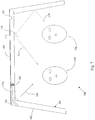
Fig. 1 illustrates an exampledirectional loudspeaker 100. Theloudspeaker system 100 may be placed in an enclosure, such as a vehicle or a home theater environment. The vehicle or home theater environment may haveboundary walls 104 defining the enclosure. The boundary walls may beceilings 105, floors,windows 107, and walls. Theloudspeaker 100 is configured to include one ormore listener positions loudspeaker 100. Theloudspeaker 100 may include at least oneloudspeaker element loudspeaker element second loudspeaker element loudspeaker element second loudspeaker element loudspeaker element - The
loudspeaker elements loudspeaker elements loudspeaker elements loudspeaker element loudspeaker element 103 may be mounted within the ceiling or headliner of a vehicle such that theloudspeaker element 103 is wholly or nearly wholly contained below the surface of the ceiling or headliner. Theloudspeaker element 103 may then be mounted with a fastener, locking ring, within a groove in the ceiling or headliner, or bolted, glued, or hinged to the ceiling or headliner. Theloudspeaker element loudspeaker element - The
loudspeaker element loudspeaker element loudspeaker element - Alternatively, the
loudspeaker element 103 may extend partially away in a downward direction from the ceiling or headliner. In that case, theloudspeaker element 103 may be mounted with a fastener to the ceiling or headliner, and theloudspeaker element 103 may be positionable about its mounted position along the boundary wall to adjust the directionality of the sound waves emanating from theloudspeaker element 103. Theloudspeaker element 103 may be further pivotable about either an axis extending perpendicular to the boundary wall plane, or pivotable about an axis formed along the intersection of the plane of the boundary wall surface and the fastening structure mounting theloudspeaker element 103 to the boundary wall. - The
loudspeaker element indirect sound field 109 and adirect sound field indirect sound field ceiling 105, floors (not shown),windows 107, or other surface of theenclosure 104. For example, inFig. 1 , theindirect sound field 109 is depicted reflecting by thewindow 107 of the vehicle. Thedirect sound field listener position 101 and theloudspeaker element direct sound field listener position 101 and theloudspeaker element direct sound field - The
indirect sound field indirect sound field loudspeaker elements listener position loudspeaker element loudspeaker element - The
loudspeaker elements indirect sound field 109 is greater than thedirect sound field 111 at thelistener position 101 within the enclosure. A path length of thedirect sound field 111 propagating from thefirst loudspeaker element 103 to thelistener position 120 may be substantially equal to a path length of theindirect sound field 119 propagating from thesecond loudspeaker element 113 to thelistener position 120. - The path that the
indirect sound field boundary walls 104 in the enclosure, creates an illusion of spaciousness for the listener located at thelistener position - The
loudspeaker elements Fig. 1 . Asecond loudspeaker element loudspeaker element - The
boundary walls 104 of the enclosure may be substantially reflective of sound waves incident on theboundary walls 104. Examples of suitable boundary walls include vehicle doors, windshields, side and rear windows, floors, seats, partitions, pillars, and seats located within a vehicle. In a home theater environment, examples of suitable boundary walls include side walls, windows, chairs, furniture, and other substantially hard furnishings. -
Fig. 2 illustrates an exampledirectional loudspeaker system 200 with twoloudspeaker elements loudspeaker elements Fig. 2 may be conventional loudspeaker systems with a channeling device acoustically coupled to the loudspeaker element, where the channeling device is operable to produce a greater indirect sound pressure than a direct sound pressure at a listener position. - In
Fig. 2 , the channeling device may be implemented as amechanical baffle loudspeaker elements baffle indirect sound field loudspeaker element indirect sound field 109 may reflect by at least one of the boundary walls or surfaces, such as theceiling 105, floors (not shown) orwindows 107 of theenclosure 104. Thedirect sound field loudspeaker element 203 to alistener position 120 not located directly below theloudspeaker element 203. Conversely, thedirect sound field different loudspeaker element 213 may radiate directly to alistener position 101 not located directly below theloudspeaker element 213. The position of thebaffle 215 creates a zone of reduced sound field below theloudspeaker element indirect sound field mechanical loudspeaker 203 is greater than thedirect sound field 121 at alistener position 101. - The
loudspeaker element surface loudspeaker element mechanical baffle surface mechanical baffle surface loudspeaker element loudspeaker elements same loudspeaker system mechanical baffle loudspeaker element baffle loudspeaker element loudspeaker element - The channeling device may also include an acoustic lens positioned proximate the radiating surface of the loudspeaker element and the baffle. The acoustic lens is further positioned between the radiating surface of the loudspeaker element and the baffle. The acoustic lens may be configurable to channel or focus the direct sound field radiated by the
loudspeaker element 103. The acoustic lens may be configured to be approximately 20% of the width of theloudspeaker element -
Fig. 3 illustrates anexample loudspeaker system 300 that indicates the position of "phantom speaker" locations. Theloudspeaker system 300 includes one or moresecond loudspeaker elements second loudspeaker elements second loudspeaker elements direct sound field second loudspeaker elements listener position - The indirect sound fields 109 and 119 produced by the
loudspeaker elements boundary listener position indirect sound field location indirect sound field indirect sound field 109 is theloudspeaker element loudspeaker element - When the
indirect sound field direct sound field sound fields second phantom loudspeaker boundary second phantom loudspeaker loudspeaker system 300 may therefore provide directivity control for spatial sound effects. -
Fig. 4 illustrates an exampledirectional loudspeaker 400 including a vehicle separated into afront compartment 430 and arear compartment 431 with twoloudspeaker elements front compartment 430 includes a driver area and front passenger area, and therear compartment 431 includes an area rearward of thefront compartment 430. Apartition 402, such as a seat or vehicle pillar, may separate thefront compartment 430 from therear compartment 431. At least one of theloudspeaker elements 403 may be located in therear compartment 431, producing adirect sound field 411, and at least one of theloudspeaker elements 413 may be located in thefront compartment 430, producing adirect sound field 422. Theindirect sound field 409 produced by theloudspeaker element 403 may reflect by therear window 407 of therear compartment 431, and theindirect sound field 419 produced by theloudspeaker element 413 may reflect by thefront windshield 417 of thefront compartment 430. Theloudspeaker 400 may be used when a listener wishes to hear multichannel sound, such as with Logic 7-configured loudspeaker systems. In such multichannel systems, it may be intended for the listener to perceive sound fields propagating from the rear of the vehicle. Theloudspeaker 400 may provide rear-emanating sound fields for listeners positioned in therear compartment 431 of the vehicle without excessive numbers of loudspeaker elements positioned throughout therear compartment 431 of the vehicle, if even possible. Theloudspeaker elements loudspeaker system 400. -
Fig. 5 illustrates an example directional loudspeaker system as inFig. 4 , withsecond loudspeaker elements second loudspeaker elements second loudspeaker elements direct sound field second loudspeaker elements listener position - The indirect sound fields 409 and 419 produced by the
loudspeaker elements boundary listener position indirect sound field location indirect sound field 409. The actual location of the source of theindirect sound field loudspeaker element loudspeaker element - When the
indirect sound field direct sound field sound fields second phantom loudspeaker boundary -
Fig. 6 illustrates an example directional loudspeaker system as inFig. 4 , where the loudspeaker system includes a vehicle separated into afront compartment 430 and arear compartment 431 with oneloudspeaker element 403 located in therear compartment 430. Theloudspeaker element 403 may be a loudspeaker system with amechanical baffle 415 positioned between theloudspeaker element 403 and thelistener position 401 positioned beneath theloudspeaker element 403. Theloudspeaker element 403 may include a radiatingsurface 421, where thebaffle 415 may be positioned proximate to the radiatingsurface 421. Thebaffle 415 may abut the radiatingsurface 421 of theloudspeaker element 403. Theindirect sound field 409 produced by theloudspeaker element 403 may reflect by therear window 407 of therear compartment 431. Thedirect sound field 411 may radiate from theloudspeaker element 403 to thelistener position 420 located in thefront compartment 430 of the vehicle. -
Fig. 7 illustrates an exampledirectional loudspeaker system 700 where theloudspeaker element 703 may include aloudspeaker element 703, and where a channeling device may include anacoustic waveguide 710, and anacoustic deflector 720. Theacoustic waveguide 710 may be positioned proximate to theloudspeaker element 703. Theacoustic deflector 720 may be positioned proximate to theacoustic waveguide 710, and may be positioned to radiate anindirect sound field 709 towards alistener position 101. Theacoustic waveguide 710 may be positioned along theceiling 105 of the vehicle enclosure, such as a vehicle headliner. Theacoustic deflector 720 may abut an intersection of theceiling 105 and aboundary wall 104 of the enclosure. An example includes the corner joint of window andceiling 105 of awindow 107 in the vehicle. Theloudspeaker system 700 may operate when the enclosure has an opening to an outside environment. Theacoustic deflector 720 andwaveguide 710 may function to provide anindirect sound field 709 to a listener positioned in thelistener position 101 when a window next to thelistener position 101 is open, for example. Without theacoustic deflector 720, theindirect sound field 709 may radiate out an open window and not reflect back to the listener. Theacoustic deflector 720 may ensure that anindirect sound field 709 is provided to the listener in that circumstance to provide a sense of spaciousness to the listener. - The
direct sound field 711 from theloudspeaker element 730 may propagate substantially parallel to a straight line between thelistener position 101 and theloudspeaker element 710. Theloudspeaker element 710 may be a dipole loudspeaker such as an electrodynamic planar loudspeaker. -
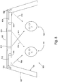
Fig. 8 illustrates an exampledirectional loudspeaker system 800 with aloudspeaker 703, anacoustic waveguide 710, and anacoustic deflector 720. Thedirectional loudspeaker system 800 also may include asecond loudspeaker 804,acoustic waveguide 821, andacoustic deflector 822 positioned opposite in configuration to thefirst loudspeaker 703,acoustic waveguide 710, andacoustic deflector 720, and operable to produce anindirect sound field 815. Theindirect sound field 815 may propagate to thelistener position 120 in a direction substantially parallel to a straight line between theacoustic deflector 822 and thelistener position 120. - The
directional loudspeaker system 800 may also include internalacoustic deflectors indirect sound field 811 may propagate from theloudspeaker 703, deflect from the internalacoustic deflector 812, and propagate to thelistener position 120. Theindirect sound field 814 may propagate from theloudspeaker 804, deflect from the internalacoustic deflector 813, and propagate to thelistener position 101. -
Fig. 9 illustrates anexample loudspeaker system 900 viewed from a location above the vehicle and looking down at the vehicle. Theloudspeaker system 900 has a similar configuration to that illustrated inFig. 3 , in that asecond loudspeaker element loudspeaker elements loudspeaker elements position loudspeaker elements phantom loudspeaker position phantom loudspeaker position - The
second loudspeaker element phantom loudspeaker loudspeaker second loudspeaker element phantom loudspeaker location loudspeaker loudspeaker loudspeaker -
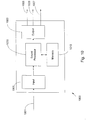
Fig. 10 illustrates anexample loudspeaker processor 1000 adapted to operate with an automobile audio system and bidirectional loudspeaker 100-800 to adjust a phase, gain, or delay parameter of the sound field for electronic enhancement, such as for multichannel sound systems like Logic 7®. Theloudspeaker processor 1000 may include aninput sound source 1001, aninput unit 1005, asound processor 1010, amemory 1015, anoutput unit 1020, and one ormore output signals loudspeaker processor 1000 may process asound source input 1001 by receiving the sound source with aninput unit 1005. Theinput unit 1005 may include a pre-processor or buffer for thesound source input 1001. Asound processor 1010 may adjust a phase, gain, or delay parameter of the sound field for electronic enhancement. The sound processor may also store a portion or all of thesound source input 1001 in amemory 1015 for buffering or later retrieval. Thememory 1015 may also store parameters for use by thesound processor 1010 in adjusting thesound source input 1001, such as gain, delay, and phase parameters. The sound processor may read these parameters from thememory 1015. Thememory 1015 may also contain system parameters for creating theindirect sound field direct sound field loudspeaker elements sound processor 1010 may generate theindirect sound field direct sound field loudspeaker element memory 1015. Thememory 1015 may also integrate with thesound processor 1010 as a single unit. - An
output unit 1020 following thesound processor 1010 may then be configured to process theindirect sound field direct sound field loudspeaker elements output unit 1020 may create one ormore channels loudspeaker elements output unit 1020 may, for instance, be configured to process the sound fields for multichannel distribution or to thedifferent loudspeaker elements - The
loudspeaker processing system 1000 may be implemented on a microprocessor or microcontroller multi-chip or integrated chip system. Theloudspeaker processor 1000 may be implemented with digital signal processing (DSP) systems, as well as DSP algorithms encoded in firmware or instructions stored in thememory 1015. -
Fig. 11 illustrates example acts that generate an indirect and direct sound field for a loudspeaker. The input sound source may be pre-processed, atact 1110, prior to reception by the loudspeaker by incorporating spatial and/or temporal effects to the input sound source. Such effects may include the "spaciousness" effects that the application replicates with the directional loudspeaker through the use of indirect and direct sound fields. Other effects may include multichannel sound effects, delays, equalization, or other electronic enhancements. A system designer may also relate specific vehicle architecture and acoustical characteristics with the input sound source, to modify the steering of the output sound source to correctly align the output sound source with the physical and non-physical (desired phantom speaker) aspects of the loudspeaker system. The loudspeaker system receives, at act 1120, the input sound source. The loudspeaker may analyze, at act 1130, the sound source for spatial and/or temporal effects included within the sound source. The analysis may be done by asound processor 1000 or other processing units included with the loudspeaker. The loudspeaker may store the sound source, atact 1140, in amemory 1015 or the loudspeaker may retrieve one or more sound source processing parameters. Examples of the sound source processing parameters include parameters for generating the indirect and direct sound fields, acoustic environment specifications, and parameters for electronic enhancement. Other example sound source processing parameters include Logic-7® sound parameters associated with the input sound encoding. In addition, thememory 1015 may buffer all or part of the sound source for processing. The loudspeaker may then incorporate, atact 1150, electronic enhancement effects into the sound source, such as gain, delay, or phase parameters. The loudspeaker may produce, atact 1160, one or more channels of sound output including indirect and direct sound field streams. The loudspeaker may then produce an indirect sound field, atact 1170, by the loudspeaker elements in the loudspeaker. Finally the loudspeaker may produce, atstep 1180, a direct sound field by the loudspeaker elements in the loudspeaker system. - The sequence diagram in
Fig. 11 may be encoded in a signal bearing medium, a computer readable medium such as a memory, programmed within a device such as one or more integrated circuits, or processed by a controller or a computer. If the methods are performed by software, the software may reside in a memory resident to or interfaced to thesound processor 1000, a communication interface, or any other type of non-volatile or volatile memory interfaced or resident to thesound processor 1010, such asmemory 1015. The memory may include an ordered listing of executable instructions for implementing logical functions. A logical function may be implemented through digital circuitry, through source code, through analog circuitry, or through an analog source such as through an analog electrical, audio, or video signal. The software may be embodied in any computer-readable or signal-bearing medium, for use by, or in connection with an instruction executable system, apparatus, or device. Such a system may include a computer-based system, a processor-containing system, or another system that may selectively fetch instructions from an instruction executable system, apparatus, or device that may also execute instructions. - A "computer-readable medium," "machine-readable medium," "propagated-signal" medium, and/or "signal-bearing medium" may comprise any means that contains, stores, communicates, propagates, or transports software for use by or in connection with an instruction executable system, apparatus, or device. The machine-readable medium may selectively be, but not limited to, an electronic, magnetic, optical, electromagnetic, infrared, or semiconductor system, apparatus, device, or propagation medium. A non-exhaustive list of examples of a machine-readable medium would include: an electrical connection "electronic" having one or more wires, a portable magnetic or optical disk, a volatile memory such as a Random Access Memory "RAM" (electronic), a Read-Only Memory "ROM" (electronic), an Erasable Programmable Read-Only Memory (EPROM or Flash memory) (electronic), or an optical fiber (optical). A machine-readable medium may also include a tangible medium upon which software is printed, as the software may be electronically stored as an image or in another format (e.g., through an optical scan), then compiled, and/or interpreted or otherwise processed. The processed medium may then be stored in a computer and/or machine memory.
- While various embodiments of the invention have been described, it will be apparent to those of ordinary skill in the art that many more embodiments and implementations are possible within the scope of the invention. Accordingly, the invention is not to be restricted except in light of the attached claims.
Claims (16)
- A loudspeaker system for placement in an at least partially enclosed space, the at least partially enclosed space having boundary walls including ceiling boundary walls (405) and at least one listener position (401, 420), the system including:a loudspeaker element (403) to be positioned within the space integral with one of the boundary walls proximate the at least one listener position (401, 420) and mounted in a ceiling boundary wall (405), anda channeling device acoustically coupled to the loudspeaker element (403) to deflect a sound field emitted from the loudspeaker element (403) so that an indirect sound field (409) and a direct sound field (411) is produced at the at least one listener position (401, 420),wherein the channeling device is implemented comprising a mechanical baffle (415) to be positioned between the loudspeaker element (403) and the listener positions (401, 420), and wherein the baffle is operable to produce a greater indirect sound pressure than a direct sound pressure at a listener position (401, 420), and wherein the indirect sound field (409) is reflected by at least one surface (407) of the at least partially enclosed space before reaching the at least one listener position (401, 420), andwherein the channeling device further comprises an acoustic lens positioned proximate to and between a radiating surface of the loudspeaker element (403) and the baffle (415).
- The loudspeaker system of claim 1, wherein the loudspeaker system comprises a first loudspeaker element (403) and a first channeling device (415) acoustically coupled to the first loudspeaker element, and wherein the loudspeaker system further comprises a second loudspeaker element (413) and a second channeling device acoustically coupled to the second loudspeaker element positioned so that a path length of the direct sound field (411) from the first loudspeaker element (403) to the at least one listener position (420) is substantially equal to a path length of the indirect sound field (419) from the second loudspeaker element (413) to the at least one listener position (420).
- The loudspeaker system of claim 2, where the at least partially enclosed space comprises a vehicle separated into a front compartment and a rear compartment, where the front compartment comprises a driver area and a front passenger area, and the rear compartment comprises an area rearward of the front compartment, and where the first loudspeaker element is positioned in the front compartment, and the second loudspeaker element is positioned in the rear compartment.
- The loudspeaker system of claim 1 or 2, where the loudspeaker system is configured for use in a home theater environment.
- The loudspeaker system of any of claims 1 - 4, where the loudspeaker system operates with an audio system to adjust a phase, gain, or delay parameter of at least one of the direct sound field or the indirect sound field for electronic enhancement.
- The loudspeaker system of claim 5, where the audio system comprises: an input unit (1005) operable to receive an input sound source; a sound processor (1010) operable to generate the indirect sound field and the direct sound field from the input sound source; and an output unit (1020) operable to output an output sound source to the loudspeaker element.
- The loudspeaker system of claim 5 or 6, where the audio system comprises: a memory (1015) operable to store one or more parameters that generate the indirect sound field and direct sound field.
- The loudspeaker system of claim 6, where the output unit may generate more than one channel of a sound output.
- The loudspeaker system of any of claims 2 - 8, where the loudspeaker element comprises a first loudspeaker element and a second loudspeaker element that are positioned so that a second direct sound field generated with the second loudspeaker element and a first indirect sound field generated with the first loudspeaker element are combinable to produce a virtual loudspeaker source perceivable by a listener as originating from a position different from a first loudspeaker element position and a second loudspeaker element position.
- The loudspeaker system of any of claims 1 - 9, where the channeling device comprises an acoustic deflector, and an acoustic waveguide coupling the loudspeaker element and the acoustic deflector, and where the loudspeaker element is positioned at a first end of the acoustic waveguide and the acoustic deflector is positioned at a second end of the acoustic waveguide.
- The loudspeaker system of any of claims 1 - 10, where the loudspeaker element comprises a dipole loudspeaker.
- The loudspeaker system of any of claims 1 - 11, where the loudspeaker element comprises an electrodynamic planar loudspeaker.
- The loudspeaker system of claim 10, where the acoustic waveguide is positioned along the ceiling boundary wall of the at least partially enclosed space.
- The loudspeaker system of claim 13, where the acoustic deflector abuts an intersection of a ceiling boundary wall and another one of the boundary walls of the at least partially enclosed space.
- The loudspeaker system of any of claims 1 - 14, where the loudspeaker element is pivotably mounted to the boundary wall
- The loudspeaker system of any of claims 10 - 14, wherein the acoustic deflector is positioned to radiate an indirect sound field towards a listener position when a window next to the listener position is open.
Applications Claiming Priority (1)
| Application Number | Priority Date | Filing Date | Title |
|---|---|---|---|
| US11/697,088 US8121336B2 (en) | 2007-04-05 | 2007-04-05 | Directional loudspeaker to reduce direct sound |
Publications (2)
| Publication Number | Publication Date |
|---|---|
| EP1978776A1 EP1978776A1 (en) | 2008-10-08 |
| EP1978776B1 true EP1978776B1 (en) | 2018-03-14 |
Family
ID=39535204
Family Applications (1)
| Application Number | Title | Priority Date | Filing Date |
|---|---|---|---|
| EP08006820.8A Active EP1978776B1 (en) | 2007-04-05 | 2008-04-03 | Directional loudspeaker to reduce direct sound |
Country Status (2)
| Country | Link |
|---|---|
| US (1) | US8121336B2 (en) |
| EP (1) | EP1978776B1 (en) |
Families Citing this family (12)
| Publication number | Priority date | Publication date | Assignee | Title |
|---|---|---|---|---|
| US20100124342A1 (en) * | 2008-11-17 | 2010-05-20 | Electronics And Telecommunications Research Institute | Forced acoustic dipole and forced acoustic multipole array using the same |
| US20100198428A1 (en) * | 2009-01-30 | 2010-08-05 | Delphi Technologies, Inc. | Multi-purpose fob system |
| US9036837B2 (en) * | 2009-06-18 | 2015-05-19 | James Tuomy | Desktop audio monitor system and method |
| KR101544919B1 (en) | 2010-07-30 | 2015-08-21 | 프라운호퍼 게젤샤프트 쭈르 푀르데룽 데어 안겐반텐 포르슝 에. 베. | Headrest speaker arrangement |
| KR101630790B1 (en) * | 2011-07-28 | 2016-06-15 | 프라운호퍼 게젤샤프트 쭈르 푀르데룽 데어 안겐반텐 포르슝 에. 베. | Vehicle with side wall speakers |
| US9088842B2 (en) | 2013-03-13 | 2015-07-21 | Bose Corporation | Grille for electroacoustic transducer |
| DE102013006068B4 (en) * | 2013-04-08 | 2018-12-13 | Volkswagen Aktiengesellschaft | "Vehicle with audio system" |
| US9327628B2 (en) | 2013-05-31 | 2016-05-03 | Bose Corporation | Automobile headrest |
| EP3063950B1 (en) * | 2013-10-30 | 2017-08-16 | L Acoustics | Sound system with improved adjustable directivity |
| US9699537B2 (en) | 2014-01-14 | 2017-07-04 | Bose Corporation | Vehicle headrest with speakers |
| WO2016182184A1 (en) | 2015-05-08 | 2016-11-17 | 삼성전자 주식회사 | Three-dimensional sound reproduction method and device |
| US9967672B2 (en) | 2015-11-11 | 2018-05-08 | Clearmotion Acquisition I Llc | Audio system |
Family Cites Families (34)
| Publication number | Priority date | Publication date | Assignee | Title |
|---|---|---|---|---|
| US4596034A (en) | 1981-01-02 | 1986-06-17 | Moncrieff J Peter | Sound reproduction system and method |
| US7164117B2 (en) | 1992-05-05 | 2007-01-16 | Automotive Technologies International, Inc. | Vehicular restraint system control system and method using multiple optical imagers |
| US7134687B2 (en) | 1992-05-05 | 2006-11-14 | Automotive Technologies International, Inc. | Rear view mirror monitor |
| US6778672B2 (en) | 1992-05-05 | 2004-08-17 | Automotive Technologies International Inc. | Audio reception control arrangement and method for a vehicle |
| US4503930A (en) | 1982-09-03 | 1985-03-12 | Mcdowell Vaughn P | Loudspeaker system |
| US4653606A (en) | 1985-03-22 | 1987-03-31 | American Telephone And Telegraph Company | Electroacoustic device with broad frequency range directional response |
| US4845759A (en) | 1986-04-25 | 1989-07-04 | Intersonics Incorporated | Sound source having a plurality of drivers operating from a virtual point |
| US5023914A (en) * | 1988-03-11 | 1991-06-11 | Bose Corporation | Acoustical frequency response improving with non-minimum phase circuitry |
| JPH02113494U (en) * | 1989-01-17 | 1990-09-11 | ||
| JP2890764B2 (en) | 1990-09-18 | 1999-05-17 | 日産自動車株式会社 | Car speaker |
| US5109416A (en) * | 1990-09-28 | 1992-04-28 | Croft James J | Dipole speaker for producing ambience sound |
| JPH05344580A (en) | 1992-06-04 | 1993-12-24 | Matsushita Electric Ind Co Ltd | Sound field reproducing device to be mounted on vehicle |
| US5809150A (en) | 1995-06-28 | 1998-09-15 | Eberbach; Steven J. | Surround sound loudspeaker system |
| US5870484A (en) | 1995-09-05 | 1999-02-09 | Greenberger; Hal | Loudspeaker array with signal dependent radiation pattern |
| US5526325A (en) | 1995-09-21 | 1996-06-11 | The United States Of America As Represented By The Secretary Of The Navy | Steerable beamformer |
| US5850060A (en) * | 1997-04-08 | 1998-12-15 | Gerber; Allen | Acoustic lens device |
| US6937740B2 (en) | 1998-08-03 | 2005-08-30 | Visteon Global Technologies, Inc. | Monopole low frequency test woofer |
| US6179359B1 (en) | 1999-08-12 | 2001-01-30 | Daimlerchrysler Corporation | Interior trim to windshield mounting arrangement |
| AU1621201A (en) | 1999-11-19 | 2001-05-30 | Gentex Corporation | Vehicle accessory microphone |
| US7120261B1 (en) | 1999-11-19 | 2006-10-10 | Gentex Corporation | Vehicle accessory microphone |
| WO2001039547A1 (en) | 1999-11-25 | 2001-05-31 | Embracing Sound Experience Ab | A method of processing and reproducing an audio stereo signal, and an audio stereo signal reproduction system |
| US6650758B1 (en) | 1999-12-23 | 2003-11-18 | Nortel Networks Limited | Adaptive dual port loudspeaker implementation for reducing lateral transmission |
| US6977653B1 (en) | 2000-03-08 | 2005-12-20 | Tektronix, Inc. | Surround sound display |
| US7164773B2 (en) | 2001-01-09 | 2007-01-16 | Bose Corporation | Vehicle electroacoustical transducing |
| US6980098B2 (en) | 2001-01-29 | 2005-12-27 | Sony Corporation | Information processing apparatus, information processing method and program executed in information processing apparatus |
| WO2002091799A2 (en) | 2001-05-03 | 2002-11-14 | Harman International Industries, Incorporated | System for transitioning from stereo to simulated surround sound |
| US7164768B2 (en) | 2001-06-21 | 2007-01-16 | Bose Corporation | Audio signal processing |
| JP4372386B2 (en) | 2002-02-04 | 2009-11-25 | 株式会社吹田屋 | General-purpose speaker and its mounting method |
| EP1282335B1 (en) | 2001-07-30 | 2008-08-27 | Matsushita Electric Industrial Co., Ltd. | Sound reproduction device |
| US6991289B2 (en) | 2002-07-31 | 2006-01-31 | Harman International Industries, Incorporated | Seatback audio system |
| US7551749B2 (en) | 2002-08-23 | 2009-06-23 | Bose Corporation | Baffle vibration reducing |
| US7343020B2 (en) * | 2002-09-18 | 2008-03-11 | Thigpen F Bruce | Vehicle audio system with directional sound and reflected audio imaging for creating a personal sound stage |
| US20060050907A1 (en) | 2004-09-03 | 2006-03-09 | Igor Levitsky | Loudspeaker with variable radiation pattern |
| US8041061B2 (en) | 2004-10-04 | 2011-10-18 | Altec Lansing, Llc | Dipole and monopole surround sound speaker system |
-
2007
- 2007-04-05 US US11/697,088 patent/US8121336B2/en active Active
-
2008
- 2008-04-03 EP EP08006820.8A patent/EP1978776B1/en active Active
Non-Patent Citations (1)
| Title |
|---|
| None * |
Also Published As
| Publication number | Publication date |
|---|---|
| EP1978776A1 (en) | 2008-10-08 |
| US20080247575A1 (en) | 2008-10-09 |
| US8121336B2 (en) | 2012-02-21 |
Similar Documents
| Publication | Publication Date | Title |
|---|---|---|
| EP1978776B1 (en) | Directional loudspeaker to reduce direct sound | |
| US9854363B2 (en) | Loudspeaker system | |
| KR100799783B1 (en) | Vehicle loudspeaker array | |
| US9049534B2 (en) | Directionally radiating sound in a vehicle | |
| US8345883B2 (en) | Audio playback method and apparatus using line array speaker unit | |
| US8014545B2 (en) | Ceiling or wall-mounted loudspeaker system with anti-diffraction wave launch device | |
| US20080273722A1 (en) | Directionally radiating sound in a vehicle | |
| KR102640919B1 (en) | Loudspeaker arrangement | |
| US20040109575A1 (en) | Vehicle audio system with directional sound and reflected audio imaging for creating a personal sound stage | |
| KR102478070B1 (en) | Loudspeaker system and configurations for directionality and dispersion control | |
| US11167700B2 (en) | Vehicle audio system | |
| CN116724566A (en) | Modular audio assembly for use with a vehicle headrest | |
| US20040047476A1 (en) | Method and system for improved sound quality of automotive audio | |
| JPH05199595A (en) | Acoustic field reproducing device on vehicle | |
| JP2009290663A (en) | On-vehicle speaker system | |
| EP3013071B1 (en) | Speaker device | |
| WO2024048084A1 (en) | Sound playback device, acoustic system, and mobile device | |
| US20220159396A1 (en) | Automotive Audio System and Method with Tri-Polar Loudspeaker Configuration and Floating Waveguide equipped Transducers in an Automotive Headrest | |
| US20230345177A1 (en) | Loudspeaker arrangement | |
| WO2023081437A1 (en) | Instrument panel speaker system | |
| JP2004168265A (en) | On-vehicle speaker device | |
| JPH05161192A (en) | On-vehicle sound field reproduction device |
Legal Events
| Date | Code | Title | Description |
|---|---|---|---|
| PUAI | Public reference made under article 153(3) epc to a published international application that has entered the european phase |
Free format text: ORIGINAL CODE: 0009012 |
|
| 17P | Request for examination filed |
Effective date: 20080403 |
|
| AK | Designated contracting states |
Kind code of ref document: A1 Designated state(s): AT BE BG CH CY CZ DE DK EE ES FI FR GB GR HR HU IE IS IT LI LT LU LV MC MT NL NO PL PT RO SE SI SK TR |
|
| AX | Request for extension of the european patent |
Extension state: AL BA MK RS |
|
| 17Q | First examination report despatched |
Effective date: 20090515 |
|
| AKX | Designation fees paid |
Designated state(s): AT BE BG CH CY CZ DE DK EE ES FI FR GB GR HR HU IE IS IT LI LT LU LV MC MT NL NO PL PT RO SE SI SK TR |
|
| GRAP | Despatch of communication of intention to grant a patent |
Free format text: ORIGINAL CODE: EPIDOSNIGR1 |
|
| RAP1 | Party data changed (applicant data changed or rights of an application transferred) |
Owner name: HARMAN INTERNATIONAL INDUSTRIES, INCORPORATED |
|
| INTG | Intention to grant announced |
Effective date: 20171023 |
|
| GRAS | Grant fee paid |
Free format text: ORIGINAL CODE: EPIDOSNIGR3 |
|
| GRAA | (expected) grant |
Free format text: ORIGINAL CODE: 0009210 |
|
| AK | Designated contracting states |
Kind code of ref document: B1 Designated state(s): AT BE BG CH CY CZ DE DK EE ES FI FR GB GR HR HU IE IS IT LI LT LU LV MC MT NL NO PL PT RO SE SI SK TR |
|
| REG | Reference to a national code |
Ref country code: GB Ref legal event code: FG4D |
|
| REG | Reference to a national code |
Ref country code: CH Ref legal event code: EP Ref country code: AT Ref legal event code: REF Ref document number: 979936 Country of ref document: AT Kind code of ref document: T Effective date: 20180315 |
|
| REG | Reference to a national code |
Ref country code: IE Ref legal event code: FG4D |
|
| REG | Reference to a national code |
Ref country code: DE Ref legal event code: R096 Ref document number: 602008054412 Country of ref document: DE |
|
| REG | Reference to a national code |
Ref country code: NL Ref legal event code: MP Effective date: 20180314 |
|
| REG | Reference to a national code |
Ref country code: LT Ref legal event code: MG4D |
|
| PG25 | Lapsed in a contracting state [announced via postgrant information from national office to epo] |
Ref country code: LT Free format text: LAPSE BECAUSE OF FAILURE TO SUBMIT A TRANSLATION OF THE DESCRIPTION OR TO PAY THE FEE WITHIN THE PRESCRIBED TIME-LIMIT Effective date: 20180314 Ref country code: CY Free format text: LAPSE BECAUSE OF FAILURE TO SUBMIT A TRANSLATION OF THE DESCRIPTION OR TO PAY THE FEE WITHIN THE PRESCRIBED TIME-LIMIT Effective date: 20180314 Ref country code: NO Free format text: LAPSE BECAUSE OF FAILURE TO SUBMIT A TRANSLATION OF THE DESCRIPTION OR TO PAY THE FEE WITHIN THE PRESCRIBED TIME-LIMIT Effective date: 20180614 Ref country code: HR Free format text: LAPSE BECAUSE OF FAILURE TO SUBMIT A TRANSLATION OF THE DESCRIPTION OR TO PAY THE FEE WITHIN THE PRESCRIBED TIME-LIMIT Effective date: 20180314 Ref country code: ES Free format text: LAPSE BECAUSE OF FAILURE TO SUBMIT A TRANSLATION OF THE DESCRIPTION OR TO PAY THE FEE WITHIN THE PRESCRIBED TIME-LIMIT Effective date: 20180314 Ref country code: FI Free format text: LAPSE BECAUSE OF FAILURE TO SUBMIT A TRANSLATION OF THE DESCRIPTION OR TO PAY THE FEE WITHIN THE PRESCRIBED TIME-LIMIT Effective date: 20180314 |
|
| REG | Reference to a national code |
Ref country code: AT Ref legal event code: MK05 Ref document number: 979936 Country of ref document: AT Kind code of ref document: T Effective date: 20180314 |
|
| PG25 | Lapsed in a contracting state [announced via postgrant information from national office to epo] |
Ref country code: GR Free format text: LAPSE BECAUSE OF FAILURE TO SUBMIT A TRANSLATION OF THE DESCRIPTION OR TO PAY THE FEE WITHIN THE PRESCRIBED TIME-LIMIT Effective date: 20180615 Ref country code: BG Free format text: LAPSE BECAUSE OF FAILURE TO SUBMIT A TRANSLATION OF THE DESCRIPTION OR TO PAY THE FEE WITHIN THE PRESCRIBED TIME-LIMIT Effective date: 20180614 Ref country code: LV Free format text: LAPSE BECAUSE OF FAILURE TO SUBMIT A TRANSLATION OF THE DESCRIPTION OR TO PAY THE FEE WITHIN THE PRESCRIBED TIME-LIMIT Effective date: 20180314 Ref country code: SE Free format text: LAPSE BECAUSE OF FAILURE TO SUBMIT A TRANSLATION OF THE DESCRIPTION OR TO PAY THE FEE WITHIN THE PRESCRIBED TIME-LIMIT Effective date: 20180314 |
|
| PG25 | Lapsed in a contracting state [announced via postgrant information from national office to epo] |
Ref country code: NL Free format text: LAPSE BECAUSE OF FAILURE TO SUBMIT A TRANSLATION OF THE DESCRIPTION OR TO PAY THE FEE WITHIN THE PRESCRIBED TIME-LIMIT Effective date: 20180314 Ref country code: PL Free format text: LAPSE BECAUSE OF FAILURE TO SUBMIT A TRANSLATION OF THE DESCRIPTION OR TO PAY THE FEE WITHIN THE PRESCRIBED TIME-LIMIT Effective date: 20180314 Ref country code: RO Free format text: LAPSE BECAUSE OF FAILURE TO SUBMIT A TRANSLATION OF THE DESCRIPTION OR TO PAY THE FEE WITHIN THE PRESCRIBED TIME-LIMIT Effective date: 20180314 Ref country code: IT Free format text: LAPSE BECAUSE OF FAILURE TO SUBMIT A TRANSLATION OF THE DESCRIPTION OR TO PAY THE FEE WITHIN THE PRESCRIBED TIME-LIMIT Effective date: 20180314 Ref country code: EE Free format text: LAPSE BECAUSE OF FAILURE TO SUBMIT A TRANSLATION OF THE DESCRIPTION OR TO PAY THE FEE WITHIN THE PRESCRIBED TIME-LIMIT Effective date: 20180314 |
|
| PG25 | Lapsed in a contracting state [announced via postgrant information from national office to epo] |
Ref country code: SK Free format text: LAPSE BECAUSE OF FAILURE TO SUBMIT A TRANSLATION OF THE DESCRIPTION OR TO PAY THE FEE WITHIN THE PRESCRIBED TIME-LIMIT Effective date: 20180314 Ref country code: CZ Free format text: LAPSE BECAUSE OF FAILURE TO SUBMIT A TRANSLATION OF THE DESCRIPTION OR TO PAY THE FEE WITHIN THE PRESCRIBED TIME-LIMIT Effective date: 20180314 Ref country code: AT Free format text: LAPSE BECAUSE OF FAILURE TO SUBMIT A TRANSLATION OF THE DESCRIPTION OR TO PAY THE FEE WITHIN THE PRESCRIBED TIME-LIMIT Effective date: 20180314 |
|
| REG | Reference to a national code |
Ref country code: CH Ref legal event code: PL |
|
| REG | Reference to a national code |
Ref country code: DE Ref legal event code: R097 Ref document number: 602008054412 Country of ref document: DE |
|
| REG | Reference to a national code |
Ref country code: BE Ref legal event code: MM Effective date: 20180430 |
|
| PG25 | Lapsed in a contracting state [announced via postgrant information from national office to epo] |
Ref country code: PT Free format text: LAPSE BECAUSE OF FAILURE TO SUBMIT A TRANSLATION OF THE DESCRIPTION OR TO PAY THE FEE WITHIN THE PRESCRIBED TIME-LIMIT Effective date: 20180716 |
|
| PLBE | No opposition filed within time limit |
Free format text: ORIGINAL CODE: 0009261 |
|
| STAA | Information on the status of an ep patent application or granted ep patent |
Free format text: STATUS: NO OPPOSITION FILED WITHIN TIME LIMIT |
|
| REG | Reference to a national code |
Ref country code: IE Ref legal event code: MM4A |
|
| PG25 | Lapsed in a contracting state [announced via postgrant information from national office to epo] |
Ref country code: LU Free format text: LAPSE BECAUSE OF NON-PAYMENT OF DUE FEES Effective date: 20180403 Ref country code: MC Free format text: LAPSE BECAUSE OF FAILURE TO SUBMIT A TRANSLATION OF THE DESCRIPTION OR TO PAY THE FEE WITHIN THE PRESCRIBED TIME-LIMIT Effective date: 20180314 Ref country code: DK Free format text: LAPSE BECAUSE OF FAILURE TO SUBMIT A TRANSLATION OF THE DESCRIPTION OR TO PAY THE FEE WITHIN THE PRESCRIBED TIME-LIMIT Effective date: 20180314 |
|
| 26N | No opposition filed |
Effective date: 20181217 |
|
| PG25 | Lapsed in a contracting state [announced via postgrant information from national office to epo] |
Ref country code: SI Free format text: LAPSE BECAUSE OF FAILURE TO SUBMIT A TRANSLATION OF THE DESCRIPTION OR TO PAY THE FEE WITHIN THE PRESCRIBED TIME-LIMIT Effective date: 20180314 Ref country code: CH Free format text: LAPSE BECAUSE OF NON-PAYMENT OF DUE FEES Effective date: 20180430 Ref country code: BE Free format text: LAPSE BECAUSE OF NON-PAYMENT OF DUE FEES Effective date: 20180430 Ref country code: LI Free format text: LAPSE BECAUSE OF NON-PAYMENT OF DUE FEES Effective date: 20180430 |
|
| PG25 | Lapsed in a contracting state [announced via postgrant information from national office to epo] |
Ref country code: IE Free format text: LAPSE BECAUSE OF NON-PAYMENT OF DUE FEES Effective date: 20180403 Ref country code: FR Free format text: LAPSE BECAUSE OF NON-PAYMENT OF DUE FEES Effective date: 20180514 |
|
| PG25 | Lapsed in a contracting state [announced via postgrant information from national office to epo] |
Ref country code: MT Free format text: LAPSE BECAUSE OF NON-PAYMENT OF DUE FEES Effective date: 20180403 |
|
| PG25 | Lapsed in a contracting state [announced via postgrant information from national office to epo] |
Ref country code: TR Free format text: LAPSE BECAUSE OF FAILURE TO SUBMIT A TRANSLATION OF THE DESCRIPTION OR TO PAY THE FEE WITHIN THE PRESCRIBED TIME-LIMIT Effective date: 20180314 |
|
| PG25 | Lapsed in a contracting state [announced via postgrant information from national office to epo] |
Ref country code: HU Free format text: LAPSE BECAUSE OF FAILURE TO SUBMIT A TRANSLATION OF THE DESCRIPTION OR TO PAY THE FEE WITHIN THE PRESCRIBED TIME-LIMIT; INVALID AB INITIO Effective date: 20080403 |
|
| PG25 | Lapsed in a contracting state [announced via postgrant information from national office to epo] |
Ref country code: IS Free format text: LAPSE BECAUSE OF FAILURE TO SUBMIT A TRANSLATION OF THE DESCRIPTION OR TO PAY THE FEE WITHIN THE PRESCRIBED TIME-LIMIT Effective date: 20180714 |
|
| PGFP | Annual fee paid to national office [announced via postgrant information from national office to epo] |
Ref country code: GB Payment date: 20230322 Year of fee payment: 16 |
|
| P01 | Opt-out of the competence of the unified patent court (upc) registered |
Effective date: 20230527 |
|
| PGFP | Annual fee paid to national office [announced via postgrant information from national office to epo] |
Ref country code: DE Payment date: 20230321 Year of fee payment: 16 |