EP1978620A2 - Agencement de fixation d'aimants sur des rotors de machines synchrones excitées en permanence - Google Patents
Agencement de fixation d'aimants sur des rotors de machines synchrones excitées en permanence Download PDFInfo
- Publication number
- EP1978620A2 EP1978620A2 EP08006721A EP08006721A EP1978620A2 EP 1978620 A2 EP1978620 A2 EP 1978620A2 EP 08006721 A EP08006721 A EP 08006721A EP 08006721 A EP08006721 A EP 08006721A EP 1978620 A2 EP1978620 A2 EP 1978620A2
- Authority
- EP
- European Patent Office
- Prior art keywords
- magnets
- bandage
- rotor
- rotor shaft
- arrangement according
- Prior art date
- Legal status (The legal status is an assumption and is not a legal conclusion. Google has not performed a legal analysis and makes no representation as to the accuracy of the status listed.)
- Withdrawn
Links
Images


Classifications
-
- H—ELECTRICITY
- H02—GENERATION; CONVERSION OR DISTRIBUTION OF ELECTRIC POWER
- H02K—DYNAMO-ELECTRIC MACHINES
- H02K1/00—Details of the magnetic circuit
- H02K1/06—Details of the magnetic circuit characterised by the shape, form or construction
- H02K1/22—Rotating parts of the magnetic circuit
- H02K1/27—Rotor cores with permanent magnets
- H02K1/2706—Inner rotors
- H02K1/272—Inner rotors the magnetisation axis of the magnets being perpendicular to the rotor axis
- H02K1/274—Inner rotors the magnetisation axis of the magnets being perpendicular to the rotor axis the rotor consisting of two or more circumferentially positioned magnets
- H02K1/2753—Inner rotors the magnetisation axis of the magnets being perpendicular to the rotor axis the rotor consisting of two or more circumferentially positioned magnets the rotor consisting of magnets or groups of magnets arranged with alternating polarity
- H02K1/278—Surface mounted magnets; Inset magnets
- H02K1/2781—Magnets shaped to vary the mechanical air gap between the magnets and the stator
-
- H—ELECTRICITY
- H02—GENERATION; CONVERSION OR DISTRIBUTION OF ELECTRIC POWER
- H02K—DYNAMO-ELECTRIC MACHINES
- H02K1/00—Details of the magnetic circuit
- H02K1/06—Details of the magnetic circuit characterised by the shape, form or construction
- H02K1/22—Rotating parts of the magnetic circuit
- H02K1/28—Means for mounting or fastening rotating magnetic parts on to, or to, the rotor structures
Definitions
- the first method is limited by the reduced holding power of adhesives at operationally elevated temperatures and at the same time high stress by centrifugal forces at high speeds. Therefore, either an increased air gap is required to account for the centrifugal deformation of the adhesive or additional securing measures for the magnets (e.g., a bandage).
- the second method requires for high speeds a complex and usually thick bandage to ensure the required bias in all operating points and to prevent an undefined lifting of the magnets of the rotor shaft.
- the lifting of the magnets is therefore regularly preventable, because an elastic bandage is used to raise them on the runner can. If the preload is then insufficient for high centrifugal forces in order to press all the magnets firmly onto the shaft, then individual magnets can lift during operation and lead to an extreme imbalance of the rotor.
- the magnetic "air gap” is increased by a large bandage thickness, so that the efficiency of the electric machine significantly reduced.
- the application of bandages with high biasing force is associated with an extremely high production cost.
- the invention has for its object to find a new way to attach permanent magnets on rotors of high-speed permanent magnet synchronous machines, with which the magnets are reliably and permanently secured against a caused by centrifugal force, unbalance-generating lifting the rotor even at high speeds.
- the object is in an arrangement for fixing magnets on the rotor of a permanent magnet synchronous machine, in which the rotor has a plurality of permanent magnets located on the outer periphery of a soft magnetic rotor shaft, wherein the magnets are non-positively supported by a non-magnetic bandage frictionally on the periphery of the rotor shaft solved that the magnets are supported on the rotor shaft in guide grooves radially movable, that the bandage is connected by means of two end-side end caps centrally with the rotor shaft, and that the end caps are elastically expandable in the radial direction, so that the bandage in a radially lifted Keep the condition of the magnets centric to the rotor axis at high speeds of rotation of the rotor shaft.
- the end caps consist of an inner and an outer ring and have a rotationally symmetrical contour to allow easy radial expansion while maintaining the concentricity of inner and outer ring.
- the rotationally symmetrical contours have expediently defined introduced material weakening to facilitate the radial expansion while maintaining concentricity.
- the end caps consist of an inner and an outer ring, which are connected to each other by radially aligned webs.
- the webs are suitably shaped from reversible stretchable material. In order to facilitate the radial change in length of the webs, these are advantageously mounted slightly inclined within a radial plane on the inner and outer ring. In another expedient variant, the webs are mounted slightly obliquely between the inner and outer ring in the axial direction.
- the end caps are attached to the two end regions of the bandage in a form-fitting manner. However, they can also be advantageously fastened to both end regions of the bandage in a material-locking manner, with one of the cohesive connections of welding, soldering and adhesive bonding preferably being used.
- rotor grooves with parallel flanks are advantageously introduced into the rotor shaft, which are provided as guide grooves for the defined radial guidance of the magnets.
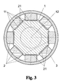
- the rotor shaft has rotor grooves with radially outwardly converging flanks, in which non-magnetic guide wedges are positively inserted, wherein the guide wedges are provided with radially outwardly diverging sliding surfaces such that the sliding surfaces of adjacent guide wedges parallel guide grooves for defined radial guidance of Forming magnets.
- the non-magnetic guide wedges are integrally attached to the rotor shaft, wherein the guide wedges are formed in the same manner with radially outwardly diverging sliding surfaces for radial guidance of the magnets.
- the invention is based on the basic idea that for cost-effective attachment of permanent magnets on rotors self-excited synchronous machines for high speeds attachments with mechanical interlocking locks or adhesives are problematic. This results from the fact that the magnets as a result of increasing centrifugal forces due to manufacturing tolerances (eg adhesive layer thickness or wedge guides) can move away from the rotor axis to different degrees and can lead to significant imbalances. Manufacturing technology simpler dimensionable bandages, which are mounted with bias on the magnet-tipped rotor, have the advantage that the centrifugal force-induced strain can be sized appropriately, but a different lifting of the magnets can also lead to unwanted imbalances.
- manufacturing tolerances eg adhesive layer thickness or wedge guides
- the invention solves this problem by suitable for the magnets sliding guides on the rotor shaft for the same conditions of Centrifugal lifting the magnets are provided within a bandage and provide stable rotationally symmetric, but radially expandable end caps on the front sides of the bandage for their concentric support even at high speeds.
- the preferably nonmagnetic end caps are made stretchable with respect to the outside diameter by a simple rotationally symmetrical profile impressed into the end caps, ie the end caps have material weakening along at least one concentric annulus that allows stretching at the end cap periphery to stretch the bandage only concentrically with the rotor axis to enable.
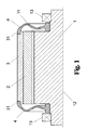
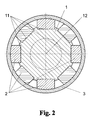
- the arrangement according to the invention consists in a rapidly rotating electrical machine - as from the synopsis of Fig. 1 and Fig. 2 to recognize - from several on the outer circumference of a rotor shaft 1 located magnet 2, which are held non-positively by a non-magnetic bandage 3 on the soft magnetic rotor shaft 1.
- the magnets 2 in guide grooves - in this example designed as rotor grooves 11 - fitted so that the magnets 2 can move only in the radial direction
- the bandage 3 is fixed by means of two end caps 4 centric to the rotor shaft 1.
- the end caps 4 are designed so that they are relatively easy to widen in the radial direction.
- a suitably rotationally symmetrical embossed contour 43 which preferably has material weakenings 44 along at least one concentric circular ring of the end cap 4.
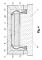
- the end caps 4 center the bandage 3 at the two end regions 31 in a form-fitting manner by means of an overlapping material ring (as in FIG Fig. 1 and 4 clear to see).
- they can also be permanently connected to the two end regions 31 of the bandage 3 (if necessary in addition), in that the connection is made in a material-locking manner (by welding, soldering, gluing, etc.).
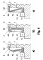
- the end caps 4 may have a wide variety of rotationally symmetrical shapes, of which three possible contours 43 in Fig. 5 are shown as profile sections a, b and c.
- the end caps 4 consist in principle of an inner ring 41, which sits on the rotor shaft 1, and an outer ring 42, which fixes the end portion 31 of the bandage 3.
- the material for the end caps 4 and the bandage 3 preferably non-magnetizable metallic materials such as aluminum, stainless steel or titanium are used. But it can also composite materials are used (eg GRP - c arbon f aserver remedye S Plastics - g f las aserver fertile S Plastics or CFRP).
- Metallic bandages 3 must be dimensioned so that they can absorb the maximum centrifugal forces occurring in the area of elastic material deformation. Since the bandage 3 does not necessarily have to prevent lifting of the magnets 2 from the shaft 1 at higher rotational speeds, the bandage 3 can be pulled over the magnets 2 without great bias. For GRP and CFRP materials, the bandages 3 can be wound around the magnets 2 with little or no bias.
- Fig. 6 shows two further embodiments of the end caps 4, in which inner ring 41 and outer ring 42 are interconnected by radial webs 45, which act as a concentric material weakening 44.
- the webs 45 are shaped so that they can extend elastically in length with larger centrifugal forces and thus allow a central radial expansion of the outer ring 42.
- the webs 45 are preferably made variable in length by inclination. This is on the one hand by tilting in the direction of the rotor axis 12 - analogous to the contours in Fig. 5a) and c) - Possible or otherwise achieved by the webs 45 - as in Fig. 6b shown - within a radial plane slightly obliquely to inner and outer ring 41 and 42 attack.
- the magnets 2 are fixed on the rotor shaft 1 guided in bearings 13 by means of a bandage 3 mounted with prestressing ( Fig. 2 - rotor at standstill). Due to the low bias, the bandage 3 can be mounted with very little effort and is held at its two end portions 31 of end caps 4 with a small radial deformation resistance concentric with the rotor shaft 1 elastic.
- the two end caps 4 ensure that the magnets 2 always remain centric to the rotor axis 12 even in the widened state of the bandage 3. As a result, extreme imbalances are avoided even at higher speeds.
- the degree of expansion of the bandage 3 at the required maximum speed is determined by the material and thickness of the bandage 3 and must be taken into account only accordingly.
- the invention can also be adapted for machines with very high speeds without an additional manufacturing effort to reduce the imbalance risk would be required at such increased speeds for the bandage 3.
Landscapes
- Engineering & Computer Science (AREA)
- Power Engineering (AREA)
- Permanent Field Magnets Of Synchronous Machinery (AREA)
Applications Claiming Priority (1)
| Application Number | Priority Date | Filing Date | Title |
|---|---|---|---|
| DE102007016771A DE102007016771B4 (de) | 2007-04-04 | 2007-04-04 | Anordnung zur Befestigung von Magneten auf Rotoren von permanent erregten Synchronmaschinen |
Publications (2)
| Publication Number | Publication Date |
|---|---|
| EP1978620A2 true EP1978620A2 (fr) | 2008-10-08 |
| EP1978620A3 EP1978620A3 (fr) | 2010-02-24 |
Family
ID=39642766
Family Applications (1)
| Application Number | Title | Priority Date | Filing Date |
|---|---|---|---|
| EP08006721A Withdrawn EP1978620A3 (fr) | 2007-04-04 | 2008-04-14 | Agencement de fixation d'aimants sur des rotors de machines synchrones excitées en permanence |
Country Status (2)
| Country | Link |
|---|---|
| EP (1) | EP1978620A3 (fr) |
| DE (1) | DE102007016771B4 (fr) |
Cited By (8)
| Publication number | Priority date | Publication date | Assignee | Title |
|---|---|---|---|---|
| EP2149965A1 (fr) * | 2008-08-01 | 2010-02-03 | Siemens Aktiengesellschaft | Rotor d'une machine synchrone doté d'aimants permanents |
| EP2390986A1 (fr) * | 2010-05-26 | 2011-11-30 | Grundfos Management a/s | Rotor à aimant permanent pour un moteur électrique |
| FR2998731A1 (fr) * | 2012-11-28 | 2014-05-30 | Sagem Defense Securite | Rotor de moteur electrique a manchon exterieur forme par enroulement, procede de fabrication d'un tel rotor et moteur electrique comprenant un tel rotor |
| DE102015207663A1 (de) | 2015-04-27 | 2016-10-27 | Schaeffler Technologies AG & Co. KG | Rotor eines Elektromotors |
| US9520752B1 (en) | 2015-09-30 | 2016-12-13 | Faraday & Future Inc. | Interior permanent magnet machine for automotive electric vehicles |
| IT201700032845A1 (it) * | 2017-03-24 | 2018-09-24 | Phase Motion Control S P A | Motore elettrico ibrido a magneti permanenti e riluttanza |
| WO2021081372A1 (fr) * | 2019-10-25 | 2021-04-29 | Jacobi Motors LLC | Moteur à mémoire à flux variable |
| EP4478586A3 (fr) * | 2023-06-13 | 2025-03-26 | Max Co., Ltd. | Moteur et machine de liaison |
Families Citing this family (6)
| Publication number | Priority date | Publication date | Assignee | Title |
|---|---|---|---|---|
| EP2978102B1 (fr) | 2014-07-22 | 2017-02-22 | Siemens Aktiengesellschaft | Procédé pour la fabrication d'un rotor |
| DE202017100697U1 (de) | 2017-02-09 | 2017-02-20 | Wittur Holding Gmbh | Elektromotor mit definiert verklebten Permanentmagneten |
| AT521408A1 (de) | 2018-07-09 | 2020-01-15 | Avl List Gmbh | Elektrische synchronmaschine mit haltefeder |
| EP3598608A1 (fr) * | 2018-07-18 | 2020-01-22 | Siemens Aktiengesellschaft | Machine à réluctance |
| FR3084220B1 (fr) * | 2018-07-23 | 2020-06-19 | Renault S.A.S | Dispositif de guidage de fils pour rotor de machine electrique synchrone de type a rotor bobine |
| DE102024201585A1 (de) * | 2024-02-21 | 2025-08-21 | Zf Friedrichshafen Ag | Rotor mit unmittelbar an den beiden Endscheiben festgelegten Einlegesegmenten sowie Verfahren zur Montage des Rotors |
Family Cites Families (8)
| Publication number | Priority date | Publication date | Assignee | Title |
|---|---|---|---|---|
| DE3719197A1 (de) * | 1987-06-09 | 1989-01-05 | Thyssen Edelstahlwerke Ag | Rotor fuer elektrische maschinen |
| JPH0984283A (ja) * | 1995-09-18 | 1997-03-28 | Honda Motor Co Ltd | ロータに対するロータ用磁石の配設構造 |
| DE19832253A1 (de) * | 1998-07-10 | 2000-01-13 | Mannesmann Vdo Ag | Elektromotor und Verwendung eines Elektromotors |
| JP2002112478A (ja) * | 2000-09-28 | 2002-04-12 | Isuzu Ceramics Res Inst Co Ltd | 永久磁石式発電・電動機のローター構造 |
| DE10216856B4 (de) * | 2002-04-16 | 2005-06-09 | Siemens Ag | Sicherung der Bandage eines permanentmagneterregten Läufers für eine elektrische Maschine |
| DE10331958A1 (de) * | 2003-02-26 | 2004-09-09 | Robert Bosch Gmbh | Elektrische Maschine mit einem Permanentmagnet |
| DE10314394B4 (de) * | 2003-03-28 | 2007-02-01 | Siemens Ag | Rotor für einen bürstenlosen Gleichstrommotor und Verfahren zur Montage eines solchen Rotors |
| JP4348606B2 (ja) * | 2003-07-30 | 2009-10-21 | 株式会社富士通ゼネラル | アキシャルギャップ型電動機 |
-
2007
- 2007-04-04 DE DE102007016771A patent/DE102007016771B4/de active Active
-
2008
- 2008-04-14 EP EP08006721A patent/EP1978620A3/fr not_active Withdrawn
Cited By (16)
| Publication number | Priority date | Publication date | Assignee | Title |
|---|---|---|---|---|
| EP2149965A1 (fr) * | 2008-08-01 | 2010-02-03 | Siemens Aktiengesellschaft | Rotor d'une machine synchrone doté d'aimants permanents |
| EP2390986A1 (fr) * | 2010-05-26 | 2011-11-30 | Grundfos Management a/s | Rotor à aimant permanent pour un moteur électrique |
| FR2998731A1 (fr) * | 2012-11-28 | 2014-05-30 | Sagem Defense Securite | Rotor de moteur electrique a manchon exterieur forme par enroulement, procede de fabrication d'un tel rotor et moteur electrique comprenant un tel rotor |
| WO2014083114A1 (fr) * | 2012-11-28 | 2014-06-05 | Sagem Defense Securite | Rotor de moteur electrique a manchon exterieur forme par enroulement, procede de fabrication d'un tel rotor et moteur electrique comprenant un tel rotor |
| CN104823358A (zh) * | 2012-11-28 | 2015-08-05 | 萨甘安全防护公司 | 具有通过绕制形成的外部套管的电机的转子、用于生产这样的转子的方法、以及包括这样的转子的电机 |
| RU2657291C2 (ru) * | 2012-11-28 | 2018-06-13 | Сафран Электроникс Энд Дифенс | Ротор электродвигателя с наружной оболочкой, образованной путем намотки, способ изготовления такого ротора и электродвигатель с таким ротором |
| US9793771B2 (en) | 2012-11-28 | 2017-10-17 | Safran Electronics & Defense | Rotor of an electric motor, with an outer sleeve formed by winding, method for producing such a rotor, and electric motor comprising such a rotor |
| DE102015207663A1 (de) | 2015-04-27 | 2016-10-27 | Schaeffler Technologies AG & Co. KG | Rotor eines Elektromotors |
| US9742251B2 (en) | 2015-09-30 | 2017-08-22 | Faraday & Future Inc. | Interior permanent magnet machine for automotive electric vehicles |
| WO2017058269A1 (fr) * | 2015-09-30 | 2017-04-06 | Faraday&Future Inc. | Machine à aimant permanent interne pour véhicules automobiles électriques |
| US9917495B2 (en) | 2015-09-30 | 2018-03-13 | Faraday & Future Inc. | Interior permanent magnet machine for automotive electric vehicles |
| US9520752B1 (en) | 2015-09-30 | 2016-12-13 | Faraday & Future Inc. | Interior permanent magnet machine for automotive electric vehicles |
| IT201700032845A1 (it) * | 2017-03-24 | 2018-09-24 | Phase Motion Control S P A | Motore elettrico ibrido a magneti permanenti e riluttanza |
| WO2021081372A1 (fr) * | 2019-10-25 | 2021-04-29 | Jacobi Motors LLC | Moteur à mémoire à flux variable |
| EP4478586A3 (fr) * | 2023-06-13 | 2025-03-26 | Max Co., Ltd. | Moteur et machine de liaison |
| AU2024204018B2 (en) * | 2023-06-13 | 2026-01-15 | Max Co., Ltd. | Motor and binding machine |
Also Published As
| Publication number | Publication date |
|---|---|
| DE102007016771A1 (de) | 2008-10-23 |
| DE102007016771B4 (de) | 2009-02-12 |
| EP1978620A3 (fr) | 2010-02-24 |
Similar Documents
| Publication | Publication Date | Title |
|---|---|---|
| EP1978620A2 (fr) | Agencement de fixation d'aimants sur des rotors de machines synchrones excitées en permanence | |
| DE102017210386B4 (de) | Rotor-Element, Rotor und elektrischer Motor | |
| DE102014226047B4 (de) | Speichenrotor mit Umspritzung | |
| EP2502331B1 (fr) | Rotor pour moteur électrique | |
| EP2639935B1 (fr) | Rotor à excitation permanente, machine électrique dotée d'un tel rotor et procédé de fabrication du rotor | |
| DE112017000001B4 (de) | Rotor einer elektrischen Rotationsmaschine, elektrische Rotationsmaschine und Rotorelement einer elektrischen Rotationsmaschine | |
| DE102019117686A1 (de) | Rotoreinrichtung für eine elektrische Maschine, insbesondere für einen Fahrzeugantrieb für ein Elektrofahrzeug | |
| EP2903136A1 (fr) | Tôle de rotor à réluctance dotée d'un évidement pour la réduction de la tension | |
| DE112009001631T5 (de) | Rotoraufbau für sich drehende Maschine vom Permanentmagnettyp | |
| WO2014166674A2 (fr) | Moteur à réluctance et rotor correspondant | |
| EP1722459B1 (fr) | Machine électrique avec dispositif pour soutenir le rotor sur le partie frontal du stator | |
| DE102020208957A1 (de) | Rotor für eine rotierende elektrische Maschine, elektrische Maschine | |
| WO2022089920A1 (fr) | Rotor pour machine synchrone à aimants permanents et machine synchrone à aimants permanents | |
| EP2068425A1 (fr) | Rotor pour une machine synchrone électrique | |
| DE102022116945A1 (de) | Rotor für eine Axialflussmaschine, sowie Verfahren zur Herstellung eines Rotors | |
| EP2790295A1 (fr) | Rotor pour un moteur à reluctance, procédé de fabrication d'un rotor pour un moteur à reluctance et machine électrique, notamment moteur à reluctance | |
| EP2128963A1 (fr) | Rotor pour une machine électrique | |
| EP2793362B1 (fr) | Moteur à reluctance et rotor associé | |
| EP2399333B1 (fr) | Configuration de rotors pour un moteur électrique | |
| EP3261221B1 (fr) | Rotor pour une machine électrique, machine électrique comprenant le rotor et procédé de fabrication du rotor | |
| EP3261224B1 (fr) | Machine électrique comprenant un rotor et procédé de fabrication de la machine électrique | |
| EP3783772B1 (fr) | Stator du générateur d'une éolienne | |
| DE102021126663A1 (de) | Rotor für eine elektrische Maschine, Verfahren zu dessen Herstellung, permanenterregte Synchronmaschine und Elektroauto mit einem solchen Rotor | |
| EP3835531B1 (fr) | Entrainement de porte doté d'une unité moteur d'encombrement réduit haute performance | |
| DE102019218654A1 (de) | Elektrische Maschine und Verfahren zur Herstellung der elektrischen Maschine |
Legal Events
| Date | Code | Title | Description |
|---|---|---|---|
| PUAI | Public reference made under article 153(3) epc to a published international application that has entered the european phase |
Free format text: ORIGINAL CODE: 0009012 |
|
| AK | Designated contracting states |
Kind code of ref document: A2 Designated state(s): AT BE BG CH CY CZ DE DK EE ES FI FR GB GR HR HU IE IS IT LI LT LU LV MC MT NL NO PL PT RO SE SI SK TR |
|
| AX | Request for extension of the european patent |
Extension state: AL BA MK RS |
|
| PUAL | Search report despatched |
Free format text: ORIGINAL CODE: 0009013 |
|
| AK | Designated contracting states |
Kind code of ref document: A3 Designated state(s): AT BE BG CH CY CZ DE DK EE ES FI FR GB GR HR HU IE IS IT LI LT LU LV MC MT NL NO PL PT RO SE SI SK TR |
|
| AX | Request for extension of the european patent |
Extension state: AL BA MK RS |
|
| AKY | No designation fees paid | ||
| STAA | Information on the status of an ep patent application or granted ep patent |
Free format text: STATUS: THE APPLICATION IS DEEMED TO BE WITHDRAWN |
|
| 18D | Application deemed to be withdrawn |
Effective date: 20100825 |
|
| REG | Reference to a national code |
Ref country code: DE Ref legal event code: R108 Effective date: 20110215 Ref country code: DE Ref legal event code: 8566 |