EP1978613A1 - Aufbau einer Energieabführungsanlage eines Elektrizitätswerks - Google Patents
Aufbau einer Energieabführungsanlage eines Elektrizitätswerks Download PDFInfo
- Publication number
- EP1978613A1 EP1978613A1 EP08102722A EP08102722A EP1978613A1 EP 1978613 A1 EP1978613 A1 EP 1978613A1 EP 08102722 A EP08102722 A EP 08102722A EP 08102722 A EP08102722 A EP 08102722A EP 1978613 A1 EP1978613 A1 EP 1978613A1
- Authority
- EP
- European Patent Office
- Prior art keywords
- station
- phases
- additional
- platform
- transformer
- Prior art date
- Legal status (The legal status is an assumption and is not a legal conclusion. Google has not performed a legal analysis and makes no representation as to the accuracy of the status listed.)
- Withdrawn
Links
Images



Classifications
-
- H—ELECTRICITY
- H02—GENERATION; CONVERSION OR DISTRIBUTION OF ELECTRIC POWER
- H02B—BOARDS, SUBSTATIONS OR SWITCHING ARRANGEMENTS FOR THE SUPPLY OR DISTRIBUTION OF ELECTRIC POWER
- H02B5/00—Non-enclosed substations; Substations with enclosed and non-enclosed equipment
-
- H—ELECTRICITY
- H02—GENERATION; CONVERSION OR DISTRIBUTION OF ELECTRIC POWER
- H02B—BOARDS, SUBSTATIONS OR SWITCHING ARRANGEMENTS FOR THE SUPPLY OR DISTRIBUTION OF ELECTRIC POWER
- H02B5/00—Non-enclosed substations; Substations with enclosed and non-enclosed equipment
- H02B5/06—Non-enclosed substations; Substations with enclosed and non-enclosed equipment gas-insulated
Definitions
- the invention relates to the field of energy evacuation produced by a power plant.
- the invention relates to the architecture of an energy evacuation station produced by a given slice of such a power plant.
- each power station has at least two power generation units, such as nuclear reactors.
- Each production unit is associated with a so-called energy evacuation station allowing the transformation of the electricity produced by the unit into a very high voltage electricity, typically 400kV and the supply of very high voltage electricity to an overhead line. for the transport of the electricity thus produced.
- the station is located immediately near the edge, that is to say within the walls of it and phase conductors of the airline are stretched above the station.
- the energy evacuation station so called includes at least a first circuit breaker connected to the step-up voltage transformer (also known as output power transformer) of the given wafer, a second circuit-breaker downstream of the first circuit-breaker and connected to the very high-voltage overhead line, and a withdrawal transformer connected to the power line between the two circuit breakers and whose function is to supply electrically all or part of the auxiliaries (electric pumps, ....) of the same given slice.
- step-up voltage transformer also known as output power transformer
- This emergency power supply thus comprises a backup circuit breaker connected to the very high voltage line of the given wafer and to a step-down transformer itself connected to all or part of the auxiliaries of the other wafer.
- the energy evacuation station so called, includes the part of the emergency power supply including the emergency circuit breaker.
- the specifications initially required physical implantation the circuit breaker connected to the extra-high voltage line outside the control panel enclosure, to use a conventional substation technology, that is to say to isolate in the air, and to carry out the connection with the step-down transformer of the additional wafer using buried cables over a long distance, typically of the order of 650m.
- FIG. 1 schematically shows the electrical installation and the implementation of the emergency power supply as requested in the initial specifications.
- the crosses represent circuit breakers integrated into substations.
- the dashed rectangles relate to metal-wrapped type stations, the dashed circle concerns a conventional type of station, that is to say to isolation in the air.
- the power station in question comprises two electricity generating units TRI, TR2 discharging electricity respectively on the very high voltage lines L1, L2.
- each TRI, TR2 wafer includes its own energy evacuation station PE1, PE2.
- the energy discharge stations PE1, PE2 each respectively comprise a power transformer TP1, TP2, a withdrawal transformer TSS1, TSS2, two main positions PP1, PP2 of the metal-enclosed type.
- Each power transformer TP1 is connected to the alternator of the first slice TR1 and, by symmetry, each TP2 is connected to the alternator of the second slice TR2.
- Each TP1 power transformer typically consists of three single-phase units.
- the withdrawal transformer TSS1 is connected to the auxiliaries of the first slice TRI, and, by symmetry, the withdrawal transformer TSS2 is connected to the auxiliaries of the second slice TR2.
- Each main station PP1 is connected to the main transformers TP1, to the withdrawal transformer TSS1 and to the very high voltage line L1, and by symmetry, the main station PP2 is connected to the main transformers TP2, to the extraction transformer TSS2 and to the very high line. high voltage L2.
- the energy evacuation station PE2 comprises part of the emergency power supply of the first slice TR1 consisting of a PS1 backup station, of metal-enclosed type, connected on the one hand to the very high line voltage L2 and secondly to an auxiliary transformer TA1 constituting another part of the emergency power supply of the first portion TR1.
- the energy evacuation station PE1 comprises a portion of the emergency power supply of the second trunk TR2 constituted by a first-aid station PS2 connected on the one hand to the very high-voltage line L1 and on the other hand to a transformer auxiliary TA2 constituting another part of the backup power supply of the second TR2 slot.
- the PS2 emergency station must be of conventional type, that is to say, isolated in the air, and it must be implanted on an area located at the top of a cliff FAL outside the power plant.
- the object of the invention is therefore to propose a simpler and less costly solution for implementing a backup power supply of a additional portion of an existing power generation plant.
- a metal-enclosed station PSEM
- GIS Gas Insulated Switchgear
- MALT disconnecting disconnector to earth
- SF6 very high voltage cable connection compartment typically 400kV
- the isolation of the (es) circuit breaker (s), disconnector (s) is achieved using of gas with high dielectric strength SF6 type.
- the energy evacuation station is contained in the perimeter of the existing power plant and makes it possible to minimize the impact of the modifications.
- the three phases of the additional station are arranged parallel to each other on a raised additional platform, the platform space delimited between two phases of the adjacent additional station comprising a hatch allowing the passage of each of the two phases of the additional station.
- the additional platform is preferably raised substantially at the same height as the energy evacuation platform. Access to all metal-encased items is thus facilitated for maintenance.
- phase of the additional station are arranged in parallel with two of them interposed individually in the space delimited by two adjacent anchoring towers. Such an arrangement can further reduce the size of the portion of the emergency power plant located in the perimeter of the first portion.
- the figure 1 represents, according to a known specifications, the electrical installation and the installation of the equipment of an electricity generating station including an existing slice and to which a slice is added.
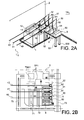
- the Figure 2A shows schematically and in perspective an embodiment of the architecture of an energy evacuation station according to the invention.
- the Figure 2B schematically represents in top view the architecture according to the Figure 2A .
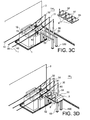
- FIGS. 3A to 3E represent the different steps of implementation of the emergency power supply portion of a power generation plant section according to the invention.
- the existing energy evacuation platform 1 of a first slice TR1 firstly supports a power transformer TP1 consisting of three single-phase units and connected to the alternator of the first slice (not shown).
- TSS1 withdrawal transformer connected to the auxiliaries of the first TR1 slot (not shown).
- a portion of the back-up power supply 5 of a second wafer TR2 comprises three phases of the additional station 50,51,52 in metal casing connected on the one hand individually to the phase conductors 40,41,42 suspended by means of overhead conductors 60,61,62 and secondly to an auxiliary transformer TA2 of a second wafer TR2. ( Figure 1 ).
- this part of the emergency power supply 5 is arranged so that the support 53 of each phase of the additional station 50,51,52 in contact with the ground covers an area located near the platform of energy evacuation 1 and not in line with the pathways of the buried high-voltage cables 70, 71, 72, 73 connected to the power transformers TP1 and to the extraction transformer TSS1. ( Figure 2B ).
- the three phases of the additional station 50, 51, 52 are coupled together by a non-rigid link.
- a rigid connection such as a drive bar allows if necessary to locate an additional station 50, 51, 52 away from another additional station 50, 51, 52.
- This non-rigid connection may consist of an electromechanical type connection, where electrical cables simultaneously send electrical energy from a common drive system to a mechanical transmission of each of the three phases of the station 50, 51, 52.
- the phases of the additional station 50, 51, 52 are arranged parallel to each other on an additional platform 8 raised substantially at the same height as the platform 1.
- the phases of the additional station 50, 51, 52 are arranged in parallel with two of them 51, 52 interspersed individually in the space delimited by two adjacent anchoring towers 30-31; 31-32 ( Figure 2B ).
- masses 530 are produced to support the metal-clad substations 50, 51, 52 in an area located near the energy evacuation platform 1 of the TR1 slice of power plant, the 530 massifs not being in line with zones of buried high-voltage cable routing 70, 71, 72, 73 ( figure 3A ).
- the supports 53 are mounted on the massifs 530 and then the phases of the additional metal-encased station 50, 51, 52 on the supports 53. More precisely, the assembly of the phases of the additional station is performed before transporting them to the power plant.
- This assembly comprises the fixing of the phases of the station 50, 51, 52 to several additional platforms 8, 80, 81 and the mounting of the phases of the station 50, 51, 52 on the supports 53 comprises the fixing of the additional platforms 8 on the supports 53 ( Figures 3C and 3D ).
Landscapes
- Engineering & Computer Science (AREA)
- Power Engineering (AREA)
- Gas-Insulated Switchgears (AREA)
Applications Claiming Priority (1)
| Application Number | Priority Date | Filing Date | Title |
|---|---|---|---|
| FR0754220A FR2914509B1 (fr) | 2007-04-02 | 2007-04-02 | Architecture d'un poste d'evacuation d'energie d'une centrale de production d'electricite |
Publications (1)
| Publication Number | Publication Date |
|---|---|
| EP1978613A1 true EP1978613A1 (de) | 2008-10-08 |
Family
ID=38738841
Family Applications (1)
| Application Number | Title | Priority Date | Filing Date |
|---|---|---|---|
| EP08102722A Withdrawn EP1978613A1 (de) | 2007-04-02 | 2008-03-18 | Aufbau einer Energieabführungsanlage eines Elektrizitätswerks |
Country Status (2)
| Country | Link |
|---|---|
| EP (1) | EP1978613A1 (de) |
| FR (1) | FR2914509B1 (de) |
Cited By (2)
| Publication number | Priority date | Publication date | Assignee | Title |
|---|---|---|---|---|
| FR2938985A1 (fr) * | 2008-11-27 | 2010-05-28 | Areva T & D Sa | Poste de distribution electrique a haute tension sous enveloppe metallique |
| WO2012007285A1 (en) * | 2010-07-15 | 2012-01-19 | Olle Corfitsson | Air-insulated switchgear |
Citations (2)
| Publication number | Priority date | Publication date | Assignee | Title |
|---|---|---|---|---|
| US5045968A (en) * | 1988-03-11 | 1991-09-03 | Hitachi, Ltd. | Gas insulated switchgear with bus-section-unit circuit breaker and disconnect switches connected to external lead-out means connectable to other gas insulated switchgear |
| US5754382A (en) * | 1995-08-30 | 1998-05-19 | Hitachi, Ltd. | Gas insulated switchgear and power transmission system using the switchgear |
-
2007
- 2007-04-02 FR FR0754220A patent/FR2914509B1/fr not_active Expired - Fee Related
-
2008
- 2008-03-18 EP EP08102722A patent/EP1978613A1/de not_active Withdrawn
Patent Citations (2)
| Publication number | Priority date | Publication date | Assignee | Title |
|---|---|---|---|---|
| US5045968A (en) * | 1988-03-11 | 1991-09-03 | Hitachi, Ltd. | Gas insulated switchgear with bus-section-unit circuit breaker and disconnect switches connected to external lead-out means connectable to other gas insulated switchgear |
| US5754382A (en) * | 1995-08-30 | 1998-05-19 | Hitachi, Ltd. | Gas insulated switchgear and power transmission system using the switchgear |
Cited By (5)
| Publication number | Priority date | Publication date | Assignee | Title |
|---|---|---|---|---|
| FR2938985A1 (fr) * | 2008-11-27 | 2010-05-28 | Areva T & D Sa | Poste de distribution electrique a haute tension sous enveloppe metallique |
| EP2192663A1 (de) * | 2008-11-27 | 2010-06-02 | Areva T&D Sas | Hochspannung metallgekapselte elektrische schaltanlage |
| CN101752798A (zh) * | 2008-11-27 | 2010-06-23 | 阿海珐输配电股份公司 | 金属封闭的高压配电站 |
| CN101752798B (zh) * | 2008-11-27 | 2014-04-16 | 阿尔斯通技术有限公司 | 金属封闭的高压配电站 |
| WO2012007285A1 (en) * | 2010-07-15 | 2012-01-19 | Olle Corfitsson | Air-insulated switchgear |
Also Published As
| Publication number | Publication date |
|---|---|
| FR2914509B1 (fr) | 2009-06-12 |
| FR2914509A1 (fr) | 2008-10-03 |
Similar Documents
| Publication | Publication Date | Title |
|---|---|---|
| CN102725524B (zh) | 一种用于提供电能的风能设备 | |
| KR20100058617A (ko) | 태양광발전 전하 감소 장치, 시스템 및 방법 | |
| EP1329008B2 (de) | Hybrid-hochspannungsstation mit gegenüberliegenden abgangen, und gekapselten schalt- undtrennmodulen dafür | |
| WO2014117899A1 (fr) | Bloc de distribution de courant continu, compact et intégré, pour sous-station ferroviaire | |
| EP1978613A1 (de) | Aufbau einer Energieabführungsanlage eines Elektrizitätswerks | |
| EP1168551B1 (de) | Hybrid-Hochspannungsstation mit metallgekapselter Sammelschienenanordnung und luftisolierter Notstromversorgung | |
| EP0235006B1 (de) | Metallgekapselte Schaltanlage mit gasdichten Teilabschnitten | |
| EP0068951B2 (de) | Gasisolierte gekapselte Zelle für elektrische Mittelspannungsanlage | |
| FR2999792A1 (fr) | Dispositif de protection d'un appareil electronique alimente par un reseau polyphase | |
| EP2192663B1 (de) | Hochspannung metallgekapselte elektrische schaltanlage | |
| FR2649551A1 (fr) | Installation de commutation isolee par un gaz | |
| EP0924826B1 (de) | Schaltvorrichtung für den Generator einer Kraftwerkanlage und einen Transformator mit einem Dreistellungsschalter | |
| EP0596790B1 (de) | Hochspannungs-Ausstattungseinheit für elektrisches Schienentreibfahrzeug | |
| FR2782418A1 (fr) | Poste de transformation electrique compact | |
| CA1127285A (fr) | Poste electrique a tres haute tension | |
| EP1030334A1 (de) | Mittelsapnnungslasttrennschaltermodul und entsprechende Energieverteilungsstation | |
| FR2735914A1 (fr) | Equipement de distribution a moyenne tension | |
| FR2566199A1 (fr) | Poste interieur a haute tension a compartimentage par des elements standard | |
| EP0338382A1 (de) | Zelle für gekapselte Mittel oder Hochspannungsstation und Station, die aus solchen Zellen aufgebaut ist | |
| WO2015003864A1 (fr) | Arrangement de commutation électrique haute tension sous enveloppe métallique | |
| EP0348312B1 (de) | Gekapselte Station für ein Hochspannungsnetz | |
| JP4738266B2 (ja) | 電力用開閉装置 | |
| EP1638179A1 (de) | Hochspannungstransformatoranordnung, Unterstation und deren Herstellungsverfahren | |
| FR2629283A1 (fr) | Travee d'un poste blinde haute tension | |
| Grima et al. | Advances in MV/LV substations |
Legal Events
| Date | Code | Title | Description |
|---|---|---|---|
| PUAI | Public reference made under article 153(3) epc to a published international application that has entered the european phase |
Free format text: ORIGINAL CODE: 0009012 |
|
| AK | Designated contracting states |
Kind code of ref document: A1 Designated state(s): AT BE BG CH CY CZ DE DK EE ES FI FR GB GR HR HU IE IS IT LI LT LU LV MC MT NL NO PL PT RO SE SI SK TR |
|
| AX | Request for extension of the european patent |
Extension state: AL BA MK RS |
|
| 17P | Request for examination filed |
Effective date: 20090406 |
|
| AKX | Designation fees paid |
Designated state(s): AT BE BG CH CY CZ DE DK EE ES FI FR GB GR HR HU IE IS IT LI LT LU LV MC MT NL NO PL PT RO SE SI SK TR |
|
| RAP1 | Party data changed (applicant data changed or rights of an application transferred) |
Owner name: AREVA T&D SAS |
|
| RAP1 | Party data changed (applicant data changed or rights of an application transferred) |
Owner name: AREVA T&D SAS |
|
| RAP1 | Party data changed (applicant data changed or rights of an application transferred) |
Owner name: ALSTOM GRID SAS |
|
| RAP1 | Party data changed (applicant data changed or rights of an application transferred) |
Owner name: ALSTOM TECHNOLOGY LTD |
|
| GRAP | Despatch of communication of intention to grant a patent |
Free format text: ORIGINAL CODE: EPIDOSNIGR1 |
|
| RIC1 | Information provided on ipc code assigned before grant |
Ipc: H02B 5/06 20060101AFI20140514BHEP |
|
| GRAP | Despatch of communication of intention to grant a patent |
Free format text: ORIGINAL CODE: EPIDOSNIGR1 |
|
| INTG | Intention to grant announced |
Effective date: 20140630 |
|
| GRAS | Grant fee paid |
Free format text: ORIGINAL CODE: EPIDOSNIGR3 |
|
| STAA | Information on the status of an ep patent application or granted ep patent |
Free format text: STATUS: GRANT OF PATENT IS INTENDED |
|
| STAA | Information on the status of an ep patent application or granted ep patent |
Free format text: STATUS: THE APPLICATION IS DEEMED TO BE WITHDRAWN |
|
| 18D | Application deemed to be withdrawn |
Effective date: 20151001 |