EP1978512A1 - Method for intentionally degrading the content of an optical recording medium - Google Patents
Method for intentionally degrading the content of an optical recording medium Download PDFInfo
- Publication number
- EP1978512A1 EP1978512A1 EP08103293A EP08103293A EP1978512A1 EP 1978512 A1 EP1978512 A1 EP 1978512A1 EP 08103293 A EP08103293 A EP 08103293A EP 08103293 A EP08103293 A EP 08103293A EP 1978512 A1 EP1978512 A1 EP 1978512A1
- Authority
- EP
- European Patent Office
- Prior art keywords
- laser
- information
- power
- zns
- resolution
- Prior art date
- Legal status (The legal status is an assumption and is not a legal conclusion. Google has not performed a legal analysis and makes no representation as to the accuracy of the status listed.)
- Granted
Links
Images
Classifications
-
- G—PHYSICS
- G11—INFORMATION STORAGE
- G11B—INFORMATION STORAGE BASED ON RELATIVE MOVEMENT BETWEEN RECORD CARRIER AND TRANSDUCER
- G11B7/00—Recording or reproducing by optical means, e.g. recording using a thermal beam of optical radiation by modifying optical properties or the physical structure, reproducing using an optical beam at lower power by sensing optical properties; Record carriers therefor
- G11B7/004—Recording, reproducing or erasing methods; Read, write or erase circuits therefor
- G11B7/0055—Erasing
-
- G—PHYSICS
- G11—INFORMATION STORAGE
- G11B—INFORMATION STORAGE BASED ON RELATIVE MOVEMENT BETWEEN RECORD CARRIER AND TRANSDUCER
- G11B7/00—Recording or reproducing by optical means, e.g. recording using a thermal beam of optical radiation by modifying optical properties or the physical structure, reproducing using an optical beam at lower power by sensing optical properties; Record carriers therefor
- G11B7/24—Record carriers characterised by shape, structure or physical properties, or by the selection of the material
Definitions
- the invention relates to the field of optical information recording.
- recording media that can be irreversibly neutralized, for example to limit the number of read accesses in cases where it is desired to avoid unauthorized use of the recorded data.
- recording media that can be irreversibly neutralized, for example to limit the number of read accesses in cases where it is desired to avoid unauthorized use of the recorded data.
- optical disc memories CDROM, audio CD, DVD etc.
- irreversible erasure of data or part of the data can serve as protection against unauthorized copying of the information contained in the memory.
- the optical data is in principle stored on the medium in the form of physical markings which are singularities of controlled dimensions which have an optical contrast enabling reading by a laser beam detection system.
- the physical marks may be imprints formed by molding a polycarbonate substrate (DVDROM for example); they are then registered once and for all; they can also be constituted by zones recorded in sensitive layers by the action of a writing light beam; the recording can then be reversible (possible erasure, or even re-recording) or irreversible (no erasure possible or rewriting).
- DVDROM polycarbonate substrate
- the recording is done by irradiating, by means of a laser diode, a colored layer which is degraded locally if the power of the write laser exceeds a threshold.
- This local degradation defines marks whose length is defined by the time during which the laser acts on the rotating disk, taking into account the speed of rotation thereof.
- phase-change material For rewritable discs writing is most often done by heating a so-called "phase-change" material by means of a writing laser diode.
- the material is for example initially in a crystalline phase; it passes locally in an amorphous state where the writing laser acts.
- the optical contrast (in reflectivity, for example) between the amorphous zones and the zones that remain crystalline is sufficient to allow the reading information thus recorded.
- Erasing is done by re-irradiating these areas by the laser diode, at a power greater than the power of the read laser but less than the power of the information writing laser. Areas that have become amorphous become recrystallized, those that are crystalline remain crystalline, and the disk is ready for a new writing operation.
- This structure comprises a substrate (preferably polycarbonate) provided with physical markings whose geometric configuration defines the recorded information, a superposition of three layers above the marks of the substrate, and a transparent protective layer above this superposition. , the superposition comprising a layer of indium antimonide or gallium inserted between two dielectric layers of a compound of zinc sulfide and silicon oxide (ZnS-SiO 2 ).
- This structure is favorable because it requires a relatively low read laser power to read the information in super-resolution with a satisfactory signal-to-noise ratio.
- the question of the reading power is critical because, on the one hand, a sufficiently high power is necessary to obtain a super-resolution effect by localized change of optical properties, but on the other hand a too high power tends to to progressively destroy the recorded information, limiting the number of possible read cycles, while as many reading cycles as possible are desired.
- a method of intentionally degrading super-resolution inscribed information in a high-resolution information optical storage structure comprising a substrate provided with physical markings whose geometric configuration defines the recorded information, a superposition of three layers above the marks of the substrate, and a transparent protective layer above this superposition, the superposition comprising a layer of indium antimonide or gallium inserted between two dielectric layers, a zinc sulphide and silicon oxide (ZnS-SiO 2 ) compound comprising a degradation operation of scrolling a laser beam on the physical marks having a power of about 30% less than the power of the a reading laser for reading the information recorded in super-resolution on the disk.
- ZnS-SiO 2 zinc sulphide and silicon oxide
- the storage structure should not be read more than N times, and that the reading system triggers after the Nth reading the application of a lower reading power which performs the degradation of sensitive information areas of the structure.
- the number N can also be contained in the structure itself, and read by the system to trigger a power modification of the read laser clean to perform the desired degradation. If the storage structure is rewritable, you can even enter the number readings already done to manage the desired moment for intentional degradation.
- a substrate 10 which is preferably an organic material, and in particular polycarbonate conventionally used for optical disks.
- the substrate will in practice be in the form of a flat disk and the information is conventionally written in the disk on substantially concentric tracks; a reading laser beam, symbolized by the arrow 20, placed in front of the disc, will see the information scroll in front of it during the rotation of the disc.
- the substrate 10 has physical marks defining the recorded information, and in this example, the physical marks are formed as a relief printed on the upper surface of the substrate.
- the relief consists of hollows whose width is approximately fixed for all the information entered, but whose length and spacing, in the direction of scrolling information, define the content of the information entered.
- the information is read by analyzing the phase of the laser beam reflected by the structure, which phase varies at the beginning and at the end of the passage of each physical mark.
- the depressions can be prerecorded by pressing the polycarbonate or the plastic substrate for example using a nickel mold which was made from very high resolution electron beam etching tools.
- the width, the length, the spacing of the physical marks may be lower than the theoretical optical resolution of the optical reading system that will be used to read them.
- the theoretical theoretical resolution limit is of the order 120 nanometers when taking precautions.
- the marks can be prerecorded with a resolution, in length or spacing, less than or equal to 80 nanometers as will be seen.
- the marks are covered with a triple layer formed in sequence by a dielectric layer 12 of ZnS-SiO 2 compound, an indium antimonide (InSb) or gallium antimonide (GaSb) layer 14, and a dielectric layer 16 of ZnS-SiO 2 compound.
- the assembly is covered by a transparent protective layer 18.
- the layer 14 made of InSb or GaSb is a layer with nonlinear optical properties, and it has been found that the reflectivity of the tri-layer structure, GaSb or InSb layer framed by the two ZnS-SiO 2 dielectric layers, could increase very much. significantly when illuminated by a laser beam with a power of 1 to 2 milliwatts (corresponding in practice to a power density of about 7 milliwatts per square micrometer).
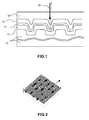
- the figure 2 recalls the way in which the pre-recorded information on the substrate can be constituted, before deposition of the superposition of three layers 12, 14, 16: blind holes of variable length and spacing.
- the arrow indicates the direction of travel of the substrate under the reading laser.
- the preferred atomic composition for the ZnS-SiO 2 compound is about 80% ZnS for 20% SiO 2 . It can range from 85/15 to 70/30.
- the atomic composition of the InSb or GaSb layer is preferably from about 45% to 55% of Sb antimony; the proportion of indium or gallium is then between 45% and the complement to 100% of the proportion of antimony.
- a stoichiometric compound In 50 Sb 50 or Ga 50 Sb 50 is well suited, but small differences in stoichiometry are acceptable.
- the deposition of the layers does not pose any particular problem; it can be done conventionally by sputtering from a target comprising the materials considered, both for the active layer and for dielectrics, or by plasma-assisted vapor deposition.
- the invention is particularly applicable for reading information from a blue laser, typically with a wavelength of about 400 nanometers, the pre-recorded information on the optical disk can then have a resolution of 100 nanometers or less that is four to five times less than the reading wavelength.
- the reading of the information will preferably be using a read laser power of about 1.5 to 2 milliwatts.
- the wavelength of the laser is preferably of the order of 400 nanometers.
- the focusing optics has a numerical aperture of about 0.85.
- the deliberate degradation of information will be done using a laser-like reading laser, or the reading laser itself, with similar focusing optics or with the reading optics itself, but with reduced laser power .
- the reduced power will be about 30% lower than the reading power. If the laser for intentional degradation of information is the read laser itself, it will be operated with a lower current and / or supply voltage during the degradation operation than during the read operation. in super-resolution.
- the degradation can be noted in particular by making measurements of fluctuations in the lengths of the marks present in the output signal with respect to the reference clock period ("jitter" measurement) of the output signal.
- the reference clock period is for example the duration T corresponding to a reference distance of 80 nm scanned by the reading laser beam when rotating the disk.
- the degree of regularity of the read marks is measured in relation (in percentage) between the periods actually detected in the read signal and the theoretical period of this signal, and it can be considered that the recorded information is degraded if the measured period fluctuation exceeds 10% while the information is precisely periodic on the disk. Indeed, if the fluctuation exceeds 10%, a sampling of the signal at the frequency 1 / T, to detect the presence or the absence of the marks, has a non-negligible probability of giving a false result.
- the practical method of measurement consists in counting the durations of the successive registered marks, determined from the output signal of the read head, and in establishing a histogram (number of marked marks having such or such a length), then determining the standard deviation of the lengths, this standard deviation representing the fluctuation with respect to the reference clock.
- the calculation can be made possibly taking into account the rotational speed fluctuations of the recording medium if its speed of rotation is not perfectly regular.
- the lower layer 12 of ZnS-SiO 2 deposited on the polycarbonate substrate 10 is designated by layer C1; the phase change layer 14 in InSb or GaSb per layer C2; the upper layer 16 of ZnS-SiO 2 is designated by layer C3; the normal reading laser power in super-resolution is designated P1; the power at which degradation is observed, irreversibly preventing super-resolution reading is designated P2.
- C1 ZnS-SiO 2 layer C2 layer InSb or GaSb C3 ZnS-SiO 2 layer Power P1 reading Power P2 degradation
- 75 nm InSb 20 nm 40 nm 1.3 mw 0.9 mw 75 nm InSb 20 nm 50 nm 1.5 mw 1.0 mw 75 nm InSb 20 nm 70 nm 1.9 mw 1.3 mw 75 nm InSb 20 nm 80 nm 2 mw 1.4 mw 75 nm GaSb 20 nm 50 nm 2 mw 1.5 mw
- the irreversible degradation method according to the invention is useful for limiting the number of accesses to a recorded media, or limiting the abusive or fraudulent use of the recorded data.
Abstract
Description
L'invention concerne le domaine de l'enregistrement optique d'informations.The invention relates to the field of optical information recording.
Dans ce domaine, il peut être intéressant de disposer de medias d'enregistrement qui soient neutralisables de manière irréversible, par exemple pour limiter le nombre d'accès en lecture dans les cas où on veut éviter une utilisation non autorisée des données enregistrées. En particulier, dans les mémoires optiques sur disque (CDROM, CD audio, DVD etc.) un effacement irréversible des données ou d'une partie des données peut servir de protection contre la copie non autorisée des informations contenues dans la mémoire.In this field, it may be advantageous to have recording media that can be irreversibly neutralized, for example to limit the number of read accesses in cases where it is desired to avoid unauthorized use of the recorded data. In particular, in optical disc memories (CDROM, audio CD, DVD etc.) irreversible erasure of data or part of the data can serve as protection against unauthorized copying of the information contained in the memory.
Les données optiques sont en principe stockées sur le support sous forme de marques physiques qui sont des singularités de dimensions contrôlées qui présentent un contraste optique permettant la lecture par un système de détection à faisceau laser.The optical data is in principle stored on the medium in the form of physical markings which are singularities of controlled dimensions which have an optical contrast enabling reading by a laser beam detection system.
Les marques physiques peuvent être des empreintes formées par moulage d'un substrat en polycarbonate (DVDROM par exemple) ; elles sont alors enregistrées une fois pour toutes ; elles peuvent être également constituées par des zones enregistrées dans des couches sensibles par l'action d'un faisceau lumineux d'écriture ; l'enregistrement peut alors être réversible (effacement possible, voire ré-enregistrement) ou irréversible (pas d'effacement possible ni de réécriture).The physical marks may be imprints formed by molding a polycarbonate substrate (DVDROM for example); they are then registered once and for all; they can also be constituted by zones recorded in sensitive layers by the action of a writing light beam; the recording can then be reversible (possible erasure, or even re-recording) or irreversible (no erasure possible or rewriting).
Typiquement, dans le cas d'un enregistrement optique irréversible, l'enregistrement se fait par irradiation, au moyen d'une diode laser, d'une couche colorée qui est dégradée localement si la puissance du laser d'écriture dépasse un seuil. Cette dégradation locale définit des marques dont la longueur est définie par le temps pendant lequel le laser agit sur le disque en rotation, compte-tenu de la vitesse de rotation de celui-ci.Typically, in the case of irreversible optical recording, the recording is done by irradiating, by means of a laser diode, a colored layer which is degraded locally if the power of the write laser exceeds a threshold. This local degradation defines marks whose length is defined by the time during which the laser acts on the rotating disk, taking into account the speed of rotation thereof.
Pour les disques réinscriptibles l'écriture se fait le plus souvent en chauffant un matériau dit "à changement de phase" grâce à une diode laser d'écriture. Le matériau est par exemple au départ dans une phase cristalline ; il passe localement dans un état amorphe là où le laser d'écriture agit. Le contraste optique (en réflectivité par exemple) entre les zones amorphes et les zones restées cristallines est suffisant pour permettre la lecture d'informations ainsi enregistrées. L'effacement se fait en insolant à nouveau ces zones par la diode laser, à une puissance supérieure à la puissance du laser de lecture mais inférieure à la puissance du laser d'écriture d'informations. Les zones devenues amorphes se recristallisent, celles qui étaient cristallines restent cristallines, et le disque est prêt pour une nouvelle opération d'écriture.For rewritable discs writing is most often done by heating a so-called "phase-change" material by means of a writing laser diode. The material is for example initially in a crystalline phase; it passes locally in an amorphous state where the writing laser acts. The optical contrast (in reflectivity, for example) between the amorphous zones and the zones that remain crystalline is sufficient to allow the reading information thus recorded. Erasing is done by re-irradiating these areas by the laser diode, at a power greater than the power of the read laser but less than the power of the information writing laser. Areas that have become amorphous become recrystallized, those that are crystalline remain crystalline, and the disk is ready for a new writing operation.
Lorsqu'on cherche à accroître la densité d'informations enregistrées sur un disque optique, on est en général limité par les performances du dispositif de lecture des informations. Le principe de base est que l'on ne peut que très difficilement lire des informations physiques inscrites dans le disque si leur dimension est inférieure à la limite de résolution du système optique qui servira à lire ces informations. Typiquement, avec une lecture par un laser rouge de longueur d'onde 650nm et une ouverture numérique de 0,6, on ne peut normalement pas espérer lire correctement des informations de résolution inférieure à 0,4 micromètre, à la rigueur 0,3 micromètre.When seeking to increase the density of information recorded on an optical disk, it is generally limited by the performance of the device for reading information. The basic principle is that it is very difficult to read physical information written in the disk if their size is less than the resolution limit of the optical system that will be used to read this information. Typically, with a red laser reading of wavelength 650nm and a numerical aperture of 0.6, one can not normally expect to correctly read information with a resolution of less than 0.4 micrometer, at most 0.3 micrometer .
Cependant, des méthodes dites de super-résolution ont été imaginées pour lire des informations dont la dimension physique est inférieure, voire même très inférieure, à la longueur d'onde. Ces méthodes se fondent sur les propriétés optiques non-linéaires de certains matériaux. Par propriétés non-linéaires, on entend le fait que certaines propriétés optiques du matériau changent en fonction de l'intensité de la lumière qu'ils reçoivent. Le laser de lecture lui-même va modifier localement les propriétés optiques du matériau par des effets thermiques, optiques, thermo-optiques et/ou optoélectroniques sur des dimensions plus petites que la dimension du spot laser de lecture ; du fait du changement de propriété, une information présente dans ce très petit volume devient détectable alors qu'elle n'aurait pas été détectable sans ce changement.However, so-called super-resolution methods have been devised to read information whose physical dimension is smaller, or even much lower, at the wavelength. These methods are based on the nonlinear optical properties of some materials. By non-linear properties is meant that certain optical properties of the material change depending on the intensity of the light they receive. The reading laser itself will locally modify the optical properties of the material by thermal, optical, thermo-optical and / or optoelectronic effects on dimensions smaller than the size of the reading laser spot; Due to the change of ownership, information in this very small volume becomes detectable even though it would not have been detectable without this change.
Le phénomène qu'on exploite est fondé principalement sur deux propriétés du laser de lecture qu'on va utiliser :
- d'une part le laser est focalisé très fortement de manière à présenter une section extrêmement petite (de l'ordre de la longueur d'onde) mais dont la distribution de puissance est gaussienne, très forte en son centre, très atténuée à la périphérie,
- et d'autre part, on choisit une puissance de laser de lecture telle que la densité de puissance sur une petite partie de la section, au centre du faisceau, modifie significativement une propriété optique de la couche, alors que la densité de puissance en dehors de cette petite portion de section ne modifie pas significativement cette propriété optique ; la propriété optique est modifiée dans un sens tendant à permettre la lecture d'une information qui ne serait pas lisible sans cette modification.
- on the one hand the laser is focused very strongly so as to have an extremely small section (of the order of the wavelength) but whose power distribution is Gaussian, very strong at its center, very attenuated at the periphery ,
- and secondly, a reading laser power is chosen such that the power density over a small portion of the section, at the center of the beam, significantly changes an optical property of the layer, while the power density outside this small portion of section does not significantly modify this optical property; the optical property is modified in a sense to allow the reading of information that would not be readable without this modification.
Tout se passe alors comme si on avait utilisé un faisceau focalisé sur un diamètre beaucoup plus petit que ce que permet sa longueur d'onde.Everything happens as if we had used a beam focused on a diameter much smaller than its wavelength allows.
Dans une précédente demande de brevet, déposée sous le numéro
Cette structure est favorable parce qu'elle nécessite une puissance laser de lecture relativement faible pour lire les informations en super-résolution avec un rapport signal/bruit satisfaisant. Or la question de la puissance de lecture est critique car, d'un côté, une puissance suffisamment élevée est nécessaire pour obtenir un effet de super-résolution par changement localisé de propriétés optiques, mais d'un autre côté une puissance trop élevée tend à détruire progressivement l'information enregistrée, limitant le nombre de cycles de lecture possible alors qu'on souhaite un nombre de cycles de lecture aussi élevé que possible.This structure is favorable because it requires a relatively low read laser power to read the information in super-resolution with a satisfactory signal-to-noise ratio. Now the question of the reading power is critical because, on the one hand, a sufficiently high power is necessary to obtain a super-resolution effect by localized change of optical properties, but on the other hand a too high power tends to to progressively destroy the recorded information, limiting the number of possible read cycles, while as many reading cycles as possible are desired.
En faisant des essais sur ces structures à base de InSb ou GaSb entre deux couches de ZnS-SiO2, on a constaté de manière surprenante que l'on pouvait à la fois
- lire correctement, sans les dégrader, des informations inscrites en super-résolution, en utilisant un laser de lecture d'une première puissance P1,
- et dégrader de manière irréversible des informations inscrites en super-résolution en les lisant avec une puissance P2 inférieure à P1.
- read correctly, without degrading them, information recorded in super-resolution, using a reading laser of a first power P1,
- and irreversibly degrading information recorded in super-resolution by reading them with a power P2 less than P1.
Cette constatation a été faite à partir de mesures répétées sur des échantillons comportant des marques régulièrement réparties, enregistrées en super-résolution.This finding was made from repeated measurements on samples with regularly distributed markings recorded in super-resolution.
Bien que ce phénomène n'ait pas jusqu'à ce jour pu être suffisamment expliqué scientifiquement, la répétition des constatations a aboutit à la conclusion qu'on pouvait utiliser industriellement ce phénomène pour neutraliser à volonté et de manière irréversible le contenu utile d'un disque optique enregistré en super-résolution. La neutralisation consiste en une dégradation de certaines zones (déterminées ou aléatoirement distribuées), rendant inutilisable le disque.Although this phenomenon has not yet been sufficiently scientifically explained, the repetition of the findings led to the conclusion that this phenomenon could be used industrially to neutralize the useful content of a device at will and irreversibly. optical disc recorded in super-resolution. Neutralization consists of a degradation of certain zones (determined or randomly distributed), rendering the disk unusable.
Par conséquent, on propose selon l'invention un procédé de dégradation intentionnelle d'informations inscrites en super-résolution dans une structure de stockage optique d'informations à haute résolution, la structure comprenant un substrat pourvu de marques physiques dont la configuration géométrique définit l'information enregistrée, une superposition de trois couches au-dessus des marques du substrat, et une couche de protection transparente au-dessus de cette superposition, la superposition comprenant une couche d'antimoniure d'indium ou de gallium insérée entre deux couches diélectriques d'un composé de sulfure de zinc et d'oxyde de silicium (ZnS-SiO2) le procédé comprenant une opération de dégradation consistant à faire défiler sur les marques physiques un faisceau laser ayant une puissance inférieure d'environ 30% à la puissance d'un laser de lecture servant à lire les informations inscrites en super-résolution sur le disque.Therefore, it is proposed according to the invention a method of intentionally degrading super-resolution inscribed information in a high-resolution information optical storage structure, the structure comprising a substrate provided with physical markings whose geometric configuration defines the recorded information, a superposition of three layers above the marks of the substrate, and a transparent protective layer above this superposition, the superposition comprising a layer of indium antimonide or gallium inserted between two dielectric layers, a zinc sulphide and silicon oxide (ZnS-SiO 2 ) compound comprising a degradation operation of scrolling a laser beam on the physical marks having a power of about 30% less than the power of the a reading laser for reading the information recorded in super-resolution on the disk.
A titre d'exemple d'utilisation, on peut prévoir que la structure de stockage ne doit pas être lue plus de N fois, et que le système de lecture déclenche après la Nième lecture l'application d'une puissance de lecture plus faible qui effectue la dégradation de zones d'informations sensibles de la structure. Le nombre N peut d'ailleurs être contenu dans la structure elle-même, et lu par le système pour déclencher une modification de puissance du laser de lecture propre à effectuer la dégradation souhaitée. Si la structure de stockage est réinscriptible, on peut même y inscrire le nombre de lectures déjà effectuées pour gérer le moment souhaité pour la dégradation intentionnelle.As an example of use, it can be expected that the storage structure should not be read more than N times, and that the reading system triggers after the Nth reading the application of a lower reading power which performs the degradation of sensitive information areas of the structure. The number N can also be contained in the structure itself, and read by the system to trigger a power modification of the read laser clean to perform the desired degradation. If the storage structure is rewritable, you can even enter the number readings already done to manage the desired moment for intentional degradation.
D'autres caractéristiques et avantages de l'invention apparaîtront à la lecture de la description détaillée qui suit et qui est faite en référence aux dessins annexés dans lesquels :
- la
figure 1 représente la structure de stockage d'informations optiques utilisé pour mettre en oeuvre l'invention ; - la
figure 2 représente une vue au microscope à force atomique d'un substrat dans lequel ont été préformées des marques de dimension multiple de 80 nanomètres espacées de distances multiples de 80 nanomètres.
- the
figure 1 represents the optical information storage structure used to implement the invention; - the
figure 2 is an atomic force microscopic view of a substrate in which multiple-dimension markings of 80 nanometers spaced multiple distances of 80 nanometers have been preformed.
Sur la
Il comprend un substrat 10, qui est de préférence un matériau organique, et notamment du polycarbonate classiquement utilisé pour des disques optiques. Le substrat sera en pratique en forme de disque plan et les informations sont classiquement inscrites dans le disque sur des pistes sensiblement concentriques ; un faisceau laser de lecture, symbolisé par la flèche 20, placé devant le disque, verra les informations défiler devant lui lors de la rotation du disque.It comprises a
Le substrat 10 comporte des marques physiques définissant l'information enregistrée, et dans cet exemple, les marques physiques sont constituées sous forme d'un relief imprimé à la surface supérieure du substrat. Le relief est par exemple constitué de creux dont la largeur est à peu près fixe pour toutes les informations inscrites, mais dont la longueur et l'espacement, dans le sens de défilement des informations, définissent le contenu de l'information inscrite. La lecture des informations se fait par analyse de la phase du faisceau laser réfléchi par la structure, phase qui varie au début et à la fin du passage de chaque marque physique. Les creux peuvent être préenregistrés par pressage du polycarbonate ou du substrat plastique par exemple à l'aide d'un moule en nickel qui a été réalisé à partir d'outils de gravure à faisceaux d'électrons de très haute résolution.The
La largeur, la longueur, l'espacement des marques physiques peuvent être inférieures à la résolution optique théorique du système optique de lecture qui servira à les lire. Typiquement, s'il s'agit d'un laser bleu de longueur d'onde 400 nanomètres environ, utilisé avec une optique de focalisation dont l'ouverture numérique est de 0,85, la limite physique théorique de résolution est de l'ordre de 120 nanomètres en prenant des précautions. Ici, les marques peuvent être préenregistrées avec une résolution, en longueur ou en espacement, inférieure ou égale à 80 nanomètres comme on le verra.The width, the length, the spacing of the physical marks may be lower than the theoretical optical resolution of the optical reading system that will be used to read them. Typically, if it is a blue laser having a wavelength of about 400 nanometers, used with a focusing optics whose numerical aperture is 0.85, the theoretical theoretical resolution limit is of the order 120 nanometers when taking precautions. Here, the marks can be prerecorded with a resolution, in length or spacing, less than or equal to 80 nanometers as will be seen.
Les marques sont recouvertes d'une triple couche constituée dans l'ordre par une couche diélectrique 12 de composé ZnS-SiO2, une couche 14 d'antimoniure d'indium (InSb) ou antimoniure de gallium (GaSb), et une couche diélectrique 16 de composé ZnS-Si02. L'ensemble est recouvert par une couche de protection transparente 18.The marks are covered with a triple layer formed in sequence by a
La couche 14 en InSb ou GaSb est une couche à propriétés optiques non linéaires, et on a constaté que le pouvoir de réflexion de la structure tri-couche, couche GaSb ou InSb encadrée par les deux couches diélectriques ZnS-SiO2, pouvait augmenter très significativement lorsqu'elle est illuminée par un faisceau laser d'une puissance de 1 à 2 milliwatts (correspondant en pratique à une densité de puissance d'environ 7 milliwatts par micromètre carré).The
La
Les essais effectués ont montré que les épaisseurs optimales des couches de la structure selon l'invention sont les suivantes :
- couche inférieure de ZnS-SiO2 : de 20 à 100 nanomètres, de préférence environ 50 à 70 nanomètres ;
- couche GaSb ou InSb : de 10 à 50 nanomètres, de préférence
environ 20 à 30 nanomètres ; - couche supérieure de ZnS-SiO2 : de 20 à 100 nanomètres, de préférence environ 50 à 60 nanomètres.
- lower layer of ZnS-SiO 2: from 20 to 100 nanometers, preferably about 50 to 70 nanometers;
- GaSb or InSb layer: 10 to 50 nanometers, preferably about 20 to 30 nanometers;
- top layer of ZnS-SiO 2 : 20 to 100 nanometers, preferably about 50 to 60 nanometers.
La composition atomique préférée pour le composé ZnS-SiO2 est d'environ 80% de ZnS pour 20% de SiO2. Elle peut aller d'un rapport 85/15 à un rapport 70/30.The preferred atomic composition for the ZnS-SiO 2 compound is about 80% ZnS for 20% SiO 2 . It can range from 85/15 to 70/30.
La composition atomique de la couche InSb ou GaSb est de préférence d'environ 45% à 55% d'antimoine Sb ; la proportion d'indium ou de gallium est alors comprise entre 45% et le complément à 100% de la proportion d'antimoine. Un composé stoechiométrique In50Sb50 ou Ga50Sb50 convient bien, mais de petits écarts à la stoechiométrie sont acceptables.The atomic composition of the InSb or GaSb layer is preferably from about 45% to 55% of Sb antimony; the proportion of indium or gallium is then between 45% and the complement to 100% of the proportion of antimony. A stoichiometric compound In 50 Sb 50 or Ga 50 Sb 50 is well suited, but small differences in stoichiometry are acceptable.
Le dépôt des couches ne pose pas de problème particulier ; il peut être fait classiquement par pulvérisation cathodique à partir d'une cible comportant les matériaux considérés, aussi bien pour la couche active que pour les diélectriques, ou par dépôt en phase vapeur assisté par plasma.The deposition of the layers does not pose any particular problem; it can be done conventionally by sputtering from a target comprising the materials considered, both for the active layer and for dielectrics, or by plasma-assisted vapor deposition.
L'invention est particulièrement applicable pour la lecture d'informations à partir d'un laser bleu, typiquement avec une longueur d'onde d'environ 400 nanomètres, les informations préenregistrées sur le disque optique pouvant alors avoir une résolution de 100 nanomètres ou moins, c'est-à-dire quatre à cinq fois moins que la longueur d'onde de lecture.The invention is particularly applicable for reading information from a blue laser, typically with a wavelength of about 400 nanometers, the pre-recorded information on the optical disk can then have a resolution of 100 nanometers or less that is four to five times less than the reading wavelength.
La lecture des informations se fera de préférence en utilisant une puissance de laser de lecture d'environ 1,5 à 2 milliwatts. La longueur d'onde du laser est de préférence de l'ordre de 400 nanomètres. L'optique de focalisation a une ouverture numérique d'environ 0,85.The reading of the information will preferably be using a read laser power of about 1.5 to 2 milliwatts. The wavelength of the laser is preferably of the order of 400 nanometers. The focusing optics has a numerical aperture of about 0.85.
La dégradation volontaire des informations se fera en utilisant un laser semblable au laser de lecture, ou le laser de lecture lui-même, avec une optique de focalisation semblable ou avec l'optique de lecture elle-même, mais avec une puissance réduite du laser. La puissance réduite sera d'environ 30% inférieure à la puissance de lecture. Si le laser servant à assurer la dégradation intentionnelle des informations est le laser de lecture lui-même, on le fera fonctionner avec un courant et/ou une tension d'alimentation plus faibles pendant l'opération de dégradation que pendant l'opération de lecture en super-résolution.The deliberate degradation of information will be done using a laser-like reading laser, or the reading laser itself, with similar focusing optics or with the reading optics itself, but with reduced laser power . The reduced power will be about 30% lower than the reading power. If the laser for intentional degradation of information is the read laser itself, it will be operated with a lower current and / or supply voltage during the degradation operation than during the read operation. in super-resolution.
La dégradation peut être constatée notamment en faisant des mesures de fluctuations des longueurs des marques présentes dans le signal de sortie par rapport à la période d'horloge de référence (mesure de "jitter" en anglais) du signal de sortie. La période d'horloge de référence est par exemple la durée T correspondant à une distance de référence de 80nm balayée par le faisceau laser de lecture lors de la rotation du disque. Le degré de régularité des marques lues se mesure en rapport (en pourcentage) entre les périodes réellement détectées dans le signal lu et la période théorique de ce signal, et on peut considérer que l'information enregistrée est dégradée si la fluctuation de période mesurée dépasse 10% alors que les informations sont précisément périodiques sur le disque. En effet, si la fluctuation dépasse 10%, un échantillonnage du signal à la fréquence 1/T, pour détecter la présence ou l'absence des marques, a une probabilité non négligeable de donner un résultat faux.The degradation can be noted in particular by making measurements of fluctuations in the lengths of the marks present in the output signal with respect to the reference clock period ("jitter" measurement) of the output signal. The reference clock period is for example the duration T corresponding to a reference distance of 80 nm scanned by the reading laser beam when rotating the disk. The degree of regularity of the read marks is measured in relation (in percentage) between the periods actually detected in the read signal and the theoretical period of this signal, and it can be considered that the recorded information is degraded if the measured period fluctuation exceeds 10% while the information is precisely periodic on the disk. Indeed, if the fluctuation exceeds 10%, a sampling of the signal at the frequency 1 / T, to detect the presence or the absence of the marks, has a non-negligible probability of giving a false result.
La méthode pratique de mesure consiste à comptabiliser les durées des marques enregistrées successives, déterminées à partir du signal de sortie de la tête de lecture, et à en établir un histogramme (nombre de marques repérées ayant telle ou telle longueur), puis à déterminer l'écart-type des longueurs, cet écart-type représentant la fluctuation par rapport à l'horloge de référence. On peut faire le calcul éventuellement en tenant compte des fluctuations de vitesse de rotation du support d'enregistrement si sa vitesse de rotation n'est pas parfaitement régulière.The practical method of measurement consists in counting the durations of the successive registered marks, determined from the output signal of the read head, and in establishing a histogram (number of marked marks having such or such a length), then determining the standard deviation of the lengths, this standard deviation representing the fluctuation with respect to the reference clock. The calculation can be made possibly taking into account the rotational speed fluctuations of the recording medium if its speed of rotation is not perfectly regular.
On a constaté que
- la lecture a de faibles puissances (inférieures à 1 mw) donnait une fluctuation faible par rapport à l'horloge de référence, inférieure à 10% (les informations en super-résolution ne pouvant cependant pas être visibles à une faible puissance) ;
- les informations lues à une puissance relativement élevée, pour laquelle l'effet de super-résolution s'applique, soit environ 1,5 à 2 milliwatts donnent une fluctuation faible, au-dessous de 10% ;
- les informations lues à une puissance moyenne (environ 1,2 à 1,5 milliwatts, soit environ 30% de moins que la puissance de lecture en super-résolution), donnent une fluctuation forte, pouvant atteindre près de 20% ;
- après une lecture à puissance moyenne, les informations en super-résolution ne peuvent plus être lues en rétablissant la puissance de lecture normale en super-résolution ; elles sont affectées d'une fluctuation forte, supérieure à 10%, et ceci a été observé de manière répétitive ; les informations sont irrémédiablement dégradées, la dégradation étant mesurée par une valeur de jitter ; l'observation au microscope à force atomique a confirmé le fait que les marques enregistrées sont détériorées.
- the reading at low power (less than 1 mw) gave a low fluctuation compared to the reference clock, less than 10% (the information in super-resolution can not however be visible at a low power);
- the information read at a relatively high power, for which the super-resolution effect applies, about 1.5 to 2 milliwatts give a low fluctuation, below 10%;
- the information read at an average power (about 1.2 to 1.5 milliwatts, or about 30% less than the super-resolution reading power), give a strong fluctuation, up to almost 20%;
- after a medium power reading, the super-resolution information can no longer be read by restoring normal super-resolution playback power; they are affected by a strong fluctuation, greater than 10%, and this has been observed repeatedly; the information is irremediably degraded, the degradation being measured by a jitter value; atomic force microscopic observation confirmed the fact that the registered marks are deteriorated.
L'observation a été répétée de multiples fois, sur des structures différentes les unes des autres et aussi bien lorsque la couche à changement de phase était de l'antimoniure d'indium que lorsqu'elle était de l'antimoniure de gallium.The observation was repeated multiple times, on different structures from each other and both when the phase change layer was indium antimonide and when it was gallium antimonide.
Les essais ont été faits sur les structures suivantes, rassemblées dans le tableau ci-dessous dans lequel :
- la couche inférieure 12 de ZnS-SiO2 déposée sur le substrat en polycarbonate 10 est désignée par couche C1 ;
- la couche à changement de phase 14 en InSb ou GaSb par couche C2 ;
- la couche supérieure 16 de ZnS-SiO2 est désignée par couche C3;
- la puissance de laser de lecture normale en super-résolution est désignée par P1 ;
- la puissance à laquelle une dégradation est constatée, empêchant irréversiblement la lecture en super-résolution est désignée par P2.
the
the
the
the normal reading laser power in super-resolution is designated P1;
the power at which degradation is observed, irreversibly preventing super-resolution reading is designated P2.
Le procédé de dégradation irréversible selon l'invention est utile pour limiter le nombre d'accès à un média enregistré, ou limiter l'utilisation abusive ou frauduleuse des données enregistrées.The irreversible degradation method according to the invention is useful for limiting the number of accesses to a recorded media, or limiting the abusive or fraudulent use of the recorded data.
Claims (8)
Applications Claiming Priority (1)
| Application Number | Priority Date | Filing Date | Title |
|---|---|---|---|
| FR0702562A FR2914774B1 (en) | 2007-04-06 | 2007-04-06 | METHOD FOR INTENTIONALLY DETERIORATING THE CONTENT OF AN OPTICAL RECORDING MEDIUM |
Publications (2)
| Publication Number | Publication Date |
|---|---|
| EP1978512A1 true EP1978512A1 (en) | 2008-10-08 |
| EP1978512B1 EP1978512B1 (en) | 2010-07-28 |
Family
ID=38657681
Family Applications (1)
| Application Number | Title | Priority Date | Filing Date |
|---|---|---|---|
| EP08103293A Not-in-force EP1978512B1 (en) | 2007-04-06 | 2008-04-01 | Method for intentionally degrading the content of an optical recording medium |
Country Status (6)
| Country | Link |
|---|---|
| US (1) | US7924690B2 (en) |
| EP (1) | EP1978512B1 (en) |
| JP (1) | JP2008257848A (en) |
| AT (1) | ATE475966T1 (en) |
| DE (1) | DE602008001914D1 (en) |
| FR (1) | FR2914774B1 (en) |
Cited By (2)
| Publication number | Priority date | Publication date | Assignee | Title |
|---|---|---|---|---|
| EP2302628A1 (en) * | 2009-09-29 | 2011-03-30 | Commissariat à l'Énergie Atomique et aux Énergies Alternatives | Super-resolution optical disk reader and reading method optimised by measuring reflectivity |
| EP2302625A1 (en) * | 2009-09-29 | 2011-03-30 | Commissariat à l'Énergie Atomique et aux Énergies Alternatives | Super-resolution optical disk reader and reading method optimised by measuring amplitude |
Families Citing this family (2)
| Publication number | Priority date | Publication date | Assignee | Title |
|---|---|---|---|---|
| JP6520137B2 (en) * | 2015-01-20 | 2019-05-29 | セイコーエプソン株式会社 | Image reader |
| CN108231093A (en) * | 2018-02-12 | 2018-06-29 | 天津天地伟业信息系统集成有限公司 | A kind of method of erasure when realizing embedded digital video recorder (DVR) and NVR optical media replications |
Citations (2)
| Publication number | Priority date | Publication date | Assignee | Title |
|---|---|---|---|---|
| JPH0729206A (en) * | 1993-07-08 | 1995-01-31 | Hitachi Ltd | Optical recording medium |
| US20050254408A1 (en) * | 2004-05-17 | 2005-11-17 | Samsung Electronics Co., Ltd. | Information storage medium having super resolution structure and apparatus for recording to and/or reproducing from the same |
Family Cites Families (4)
| Publication number | Priority date | Publication date | Assignee | Title |
|---|---|---|---|---|
| FR700938A (en) | 1930-08-21 | 1931-03-09 | Clayton Mark & Company | Improvements in processes and apparatus for electric pipe welding |
| US6404722B1 (en) * | 2000-08-01 | 2002-06-11 | Ritek Corporation | Method of increasing recording density and capacity of a compact disc |
| KR100601700B1 (en) * | 2004-08-25 | 2006-07-14 | 삼성전자주식회사 | Super resolution information storage medium, method and apparatus for recording and/or reproducing data on/from the same |
| WO2006135180A1 (en) * | 2005-06-13 | 2006-12-21 | Samsung Electronics Co., Ltd. | Super resolution medium |
-
2007
- 2007-04-06 FR FR0702562A patent/FR2914774B1/en not_active Expired - Fee Related
-
2008
- 2008-04-01 US US12/060,439 patent/US7924690B2/en not_active Expired - Fee Related
- 2008-04-01 DE DE602008001914T patent/DE602008001914D1/en active Active
- 2008-04-01 EP EP08103293A patent/EP1978512B1/en not_active Not-in-force
- 2008-04-01 AT AT08103293T patent/ATE475966T1/en not_active IP Right Cessation
- 2008-04-04 JP JP2008098220A patent/JP2008257848A/en active Pending
Patent Citations (2)
| Publication number | Priority date | Publication date | Assignee | Title |
|---|---|---|---|---|
| JPH0729206A (en) * | 1993-07-08 | 1995-01-31 | Hitachi Ltd | Optical recording medium |
| US20050254408A1 (en) * | 2004-05-17 | 2005-11-17 | Samsung Electronics Co., Ltd. | Information storage medium having super resolution structure and apparatus for recording to and/or reproducing from the same |
Non-Patent Citations (1)
| Title |
|---|
| MASAKI YAMAMOTO ET AL.: "Super-Resolution Optical Disc with High Readout Stability Using a Zinc Oxide Thin Film", JAPANESE JOURNAL OF APPLIED PHYSICS, vol. 43, no. 7B, 2004, pages 4959 - 4963, XP007903495 * |
Cited By (5)
| Publication number | Priority date | Publication date | Assignee | Title |
|---|---|---|---|---|
| EP2302628A1 (en) * | 2009-09-29 | 2011-03-30 | Commissariat à l'Énergie Atomique et aux Énergies Alternatives | Super-resolution optical disk reader and reading method optimised by measuring reflectivity |
| EP2302625A1 (en) * | 2009-09-29 | 2011-03-30 | Commissariat à l'Énergie Atomique et aux Énergies Alternatives | Super-resolution optical disk reader and reading method optimised by measuring amplitude |
| FR2950727A1 (en) * | 2009-09-29 | 2011-04-01 | Commissariat Energie Atomique | SUPER-RESOLUTION OPTICAL DISK DRIVE AND OPTIMIZED READING METHOD BY REFLECTIVITY MEASUREMENT |
| FR2950726A1 (en) * | 2009-09-29 | 2011-04-01 | Commissariat Energie Atomique | SUPER-RESOLUTION OPTICAL DISK DRIVE AND OPTIMIZED READING METHOD BY MEASURING AMPLITUDE |
| US8355303B2 (en) | 2009-09-29 | 2013-01-15 | Commissariat A L'energie Atomique | Super-resolution optical disc reader and read method optimized through reflectivity measurement |
Also Published As
| Publication number | Publication date |
|---|---|
| EP1978512B1 (en) | 2010-07-28 |
| JP2008257848A (en) | 2008-10-23 |
| ATE475966T1 (en) | 2010-08-15 |
| DE602008001914D1 (en) | 2010-09-09 |
| US7924690B2 (en) | 2011-04-12 |
| FR2914774A1 (en) | 2008-10-10 |
| US20080259778A1 (en) | 2008-10-23 |
| FR2914774B1 (en) | 2009-05-15 |
Similar Documents
| Publication | Publication Date | Title |
|---|---|---|
| EP0033046B1 (en) | Method for the thermo-optical recording of data and record carrier to carry out this method | |
| EP1978512B1 (en) | Method for intentionally degrading the content of an optical recording medium | |
| EP1978517B1 (en) | Super-resolution optical recording medium | |
| EP2115745B1 (en) | High resolution optical information storage medium | |
| EP1285440B1 (en) | Irreversible optical recording medium | |
| FR2958778A1 (en) | RECOVERY MEDIUM REVERSIBLE BY OPTICAL INFORMATION STORAGE, REVERSIBLE RECORDING METHOD ON SUCH A MEDIUM. | |
| EP2293299B1 (en) | Optical storage medium comprising a super-resolution structure with grainy impurities of a dielectric material. | |
| EP2302628A1 (en) | Super-resolution optical disk reader and reading method optimised by measuring reflectivity | |
| JP2003168244A (en) | Optical information recording medium | |
| FR2929747A1 (en) | SUPER-RESOLUTION OPTICAL DISK WITH HIGH READING STABILITY | |
| EP2302625A1 (en) | Super-resolution optical disk reader and reading method optimised by measuring amplitude | |
| JPH0793806A (en) | Information recording medium and information recording method | |
| EP2250644B1 (en) | Structure for high density optical storage | |
| Fang et al. | Implementation of practical super-resolution near-field structure system using commercial drive | |
| EP2622602B1 (en) | Optically recoring medium and legally secure recording | |
| EP1842187A1 (en) | Irreversible optical recording medium comprising a track with low raised zones and method for using same | |
| FR2882851A1 (en) | OPTICAL DATA RECORDING MEDIUM COMPRISING A THIN ALLOY OF TIN AND TENSILE ALLOY | |
| JP2007048344A (en) | Optical disk and optical disk reproducing device | |
| FR2944132A1 (en) | OPTICAL INFORMATION STORAGE STRUCTURE AND METHOD FOR OPTIMIZING THE PRODUCTION OF SAID STRUCTURE. | |
| WO2010090004A1 (en) | Optical information recording medium, recording method, reproduction method, and recording/reproduction device |
Legal Events
| Date | Code | Title | Description |
|---|---|---|---|
| PUAI | Public reference made under article 153(3) epc to a published international application that has entered the european phase |
Free format text: ORIGINAL CODE: 0009012 |
|
| AK | Designated contracting states |
Kind code of ref document: A1 Designated state(s): AT BE BG CH CY CZ DE DK EE ES FI FR GB GR HR HU IE IS IT LI LT LU LV MC MT NL NO PL PT RO SE SI SK TR |
|
| AX | Request for extension of the european patent |
Extension state: AL BA MK RS |
|
| 17P | Request for examination filed |
Effective date: 20090212 |
|
| AKX | Designation fees paid |
Designated state(s): AT BE BG CH CY CZ DE DK EE ES FI FR GB GR HR HU IE IS IT LI LT LU LV MC MT NL NO PL PT RO SE SI SK TR |
|
| GRAP | Despatch of communication of intention to grant a patent |
Free format text: ORIGINAL CODE: EPIDOSNIGR1 |
|
| RAP1 | Party data changed (applicant data changed or rights of an application transferred) |
Owner name: COMMISSARIAT A L'ENERGIE ATOMIQUE ET AUX ENERGIES |
|
| GRAS | Grant fee paid |
Free format text: ORIGINAL CODE: EPIDOSNIGR3 |
|
| GRAA | (expected) grant |
Free format text: ORIGINAL CODE: 0009210 |
|
| AK | Designated contracting states |
Kind code of ref document: B1 Designated state(s): AT BE BG CH CY CZ DE DK EE ES FI FR GB GR HR HU IE IS IT LI LT LU LV MC MT NL NO PL PT RO SE SI SK TR |
|
| REG | Reference to a national code |
Ref country code: GB Ref legal event code: FG4D Free format text: NOT ENGLISH |
|
| REG | Reference to a national code |
Ref country code: CH Ref legal event code: EP |
|
| REG | Reference to a national code |
Ref country code: IE Ref legal event code: FG4D Free format text: LANGUAGE OF EP DOCUMENT: FRENCH |
|
| REF | Corresponds to: |
Ref document number: 602008001914 Country of ref document: DE Date of ref document: 20100909 Kind code of ref document: P |
|
| REG | Reference to a national code |
Ref country code: NL Ref legal event code: VDEP Effective date: 20100728 |
|
| LTIE | Lt: invalidation of european patent or patent extension |
Effective date: 20100728 |
|
| PG25 | Lapsed in a contracting state [announced via postgrant information from national office to epo] |
Ref country code: FI Free format text: LAPSE BECAUSE OF FAILURE TO SUBMIT A TRANSLATION OF THE DESCRIPTION OR TO PAY THE FEE WITHIN THE PRESCRIBED TIME-LIMIT Effective date: 20100728 Ref country code: AT Free format text: LAPSE BECAUSE OF FAILURE TO SUBMIT A TRANSLATION OF THE DESCRIPTION OR TO PAY THE FEE WITHIN THE PRESCRIBED TIME-LIMIT Effective date: 20100728 Ref country code: LT Free format text: LAPSE BECAUSE OF FAILURE TO SUBMIT A TRANSLATION OF THE DESCRIPTION OR TO PAY THE FEE WITHIN THE PRESCRIBED TIME-LIMIT Effective date: 20100728 Ref country code: NL Free format text: LAPSE BECAUSE OF FAILURE TO SUBMIT A TRANSLATION OF THE DESCRIPTION OR TO PAY THE FEE WITHIN THE PRESCRIBED TIME-LIMIT Effective date: 20100728 Ref country code: NO Free format text: LAPSE BECAUSE OF FAILURE TO SUBMIT A TRANSLATION OF THE DESCRIPTION OR TO PAY THE FEE WITHIN THE PRESCRIBED TIME-LIMIT Effective date: 20101028 |
|
| PG25 | Lapsed in a contracting state [announced via postgrant information from national office to epo] |
Ref country code: SI Free format text: LAPSE BECAUSE OF FAILURE TO SUBMIT A TRANSLATION OF THE DESCRIPTION OR TO PAY THE FEE WITHIN THE PRESCRIBED TIME-LIMIT Effective date: 20100728 Ref country code: IS Free format text: LAPSE BECAUSE OF FAILURE TO SUBMIT A TRANSLATION OF THE DESCRIPTION OR TO PAY THE FEE WITHIN THE PRESCRIBED TIME-LIMIT Effective date: 20101128 Ref country code: PL Free format text: LAPSE BECAUSE OF FAILURE TO SUBMIT A TRANSLATION OF THE DESCRIPTION OR TO PAY THE FEE WITHIN THE PRESCRIBED TIME-LIMIT Effective date: 20100728 Ref country code: HR Free format text: LAPSE BECAUSE OF FAILURE TO SUBMIT A TRANSLATION OF THE DESCRIPTION OR TO PAY THE FEE WITHIN THE PRESCRIBED TIME-LIMIT Effective date: 20100728 Ref country code: CY Free format text: LAPSE BECAUSE OF FAILURE TO SUBMIT A TRANSLATION OF THE DESCRIPTION OR TO PAY THE FEE WITHIN THE PRESCRIBED TIME-LIMIT Effective date: 20100728 Ref country code: BG Free format text: LAPSE BECAUSE OF FAILURE TO SUBMIT A TRANSLATION OF THE DESCRIPTION OR TO PAY THE FEE WITHIN THE PRESCRIBED TIME-LIMIT Effective date: 20101028 |
|
| REG | Reference to a national code |
Ref country code: IE Ref legal event code: FD4D |
|
| PG25 | Lapsed in a contracting state [announced via postgrant information from national office to epo] |
Ref country code: SE Free format text: LAPSE BECAUSE OF FAILURE TO SUBMIT A TRANSLATION OF THE DESCRIPTION OR TO PAY THE FEE WITHIN THE PRESCRIBED TIME-LIMIT Effective date: 20100728 Ref country code: GR Free format text: LAPSE BECAUSE OF FAILURE TO SUBMIT A TRANSLATION OF THE DESCRIPTION OR TO PAY THE FEE WITHIN THE PRESCRIBED TIME-LIMIT Effective date: 20101029 Ref country code: LV Free format text: LAPSE BECAUSE OF FAILURE TO SUBMIT A TRANSLATION OF THE DESCRIPTION OR TO PAY THE FEE WITHIN THE PRESCRIBED TIME-LIMIT Effective date: 20100728 |
|
| PG25 | Lapsed in a contracting state [announced via postgrant information from national office to epo] |
Ref country code: DK Free format text: LAPSE BECAUSE OF FAILURE TO SUBMIT A TRANSLATION OF THE DESCRIPTION OR TO PAY THE FEE WITHIN THE PRESCRIBED TIME-LIMIT Effective date: 20100728 Ref country code: IE Free format text: LAPSE BECAUSE OF FAILURE TO SUBMIT A TRANSLATION OF THE DESCRIPTION OR TO PAY THE FEE WITHIN THE PRESCRIBED TIME-LIMIT Effective date: 20100728 |
|
| PG25 | Lapsed in a contracting state [announced via postgrant information from national office to epo] |
Ref country code: EE Free format text: LAPSE BECAUSE OF FAILURE TO SUBMIT A TRANSLATION OF THE DESCRIPTION OR TO PAY THE FEE WITHIN THE PRESCRIBED TIME-LIMIT Effective date: 20100728 Ref country code: CZ Free format text: LAPSE BECAUSE OF FAILURE TO SUBMIT A TRANSLATION OF THE DESCRIPTION OR TO PAY THE FEE WITHIN THE PRESCRIBED TIME-LIMIT Effective date: 20100728 Ref country code: RO Free format text: LAPSE BECAUSE OF FAILURE TO SUBMIT A TRANSLATION OF THE DESCRIPTION OR TO PAY THE FEE WITHIN THE PRESCRIBED TIME-LIMIT Effective date: 20100728 Ref country code: SK Free format text: LAPSE BECAUSE OF FAILURE TO SUBMIT A TRANSLATION OF THE DESCRIPTION OR TO PAY THE FEE WITHIN THE PRESCRIBED TIME-LIMIT Effective date: 20100728 |
|
| PLBE | No opposition filed within time limit |
Free format text: ORIGINAL CODE: 0009261 |
|
| STAA | Information on the status of an ep patent application or granted ep patent |
Free format text: STATUS: NO OPPOSITION FILED WITHIN TIME LIMIT |
|
| PG25 | Lapsed in a contracting state [announced via postgrant information from national office to epo] |
Ref country code: ES Free format text: LAPSE BECAUSE OF FAILURE TO SUBMIT A TRANSLATION OF THE DESCRIPTION OR TO PAY THE FEE WITHIN THE PRESCRIBED TIME-LIMIT Effective date: 20101108 |
|
| 26N | No opposition filed |
Effective date: 20110429 |
|
| REG | Reference to a national code |
Ref country code: DE Ref legal event code: R097 Ref document number: 602008001914 Country of ref document: DE Effective date: 20110429 |
|
| BERE | Be: lapsed |
Owner name: COMMISSARIAT A L'ENERGIE ATOMIQUE ET AUX ENERGIES Effective date: 20110430 |
|
| PG25 | Lapsed in a contracting state [announced via postgrant information from national office to epo] |
Ref country code: MC Free format text: LAPSE BECAUSE OF NON-PAYMENT OF DUE FEES Effective date: 20110430 |
|
| PG25 | Lapsed in a contracting state [announced via postgrant information from national office to epo] |
Ref country code: MT Free format text: LAPSE BECAUSE OF FAILURE TO SUBMIT A TRANSLATION OF THE DESCRIPTION OR TO PAY THE FEE WITHIN THE PRESCRIBED TIME-LIMIT Effective date: 20100728 |
|
| PG25 | Lapsed in a contracting state [announced via postgrant information from national office to epo] |
Ref country code: BE Free format text: LAPSE BECAUSE OF NON-PAYMENT OF DUE FEES Effective date: 20110430 |
|
| PGFP | Annual fee paid to national office [announced via postgrant information from national office to epo] |
Ref country code: IT Payment date: 20120420 Year of fee payment: 5 |
|
| REG | Reference to a national code |
Ref country code: CH Ref legal event code: PL |
|
| PG25 | Lapsed in a contracting state [announced via postgrant information from national office to epo] |
Ref country code: LI Free format text: LAPSE BECAUSE OF NON-PAYMENT OF DUE FEES Effective date: 20120430 Ref country code: CH Free format text: LAPSE BECAUSE OF NON-PAYMENT OF DUE FEES Effective date: 20120430 |
|
| PG25 | Lapsed in a contracting state [announced via postgrant information from national office to epo] |
Ref country code: LU Free format text: LAPSE BECAUSE OF NON-PAYMENT OF DUE FEES Effective date: 20110401 |
|
| PG25 | Lapsed in a contracting state [announced via postgrant information from national office to epo] |
Ref country code: PT Free format text: LAPSE BECAUSE OF NON-PAYMENT OF DUE FEES Effective date: 20100728 |
|
| PG25 | Lapsed in a contracting state [announced via postgrant information from national office to epo] |
Ref country code: TR Free format text: LAPSE BECAUSE OF FAILURE TO SUBMIT A TRANSLATION OF THE DESCRIPTION OR TO PAY THE FEE WITHIN THE PRESCRIBED TIME-LIMIT Effective date: 20100728 |
|
| PG25 | Lapsed in a contracting state [announced via postgrant information from national office to epo] |
Ref country code: HU Free format text: LAPSE BECAUSE OF FAILURE TO SUBMIT A TRANSLATION OF THE DESCRIPTION OR TO PAY THE FEE WITHIN THE PRESCRIBED TIME-LIMIT Effective date: 20100728 |
|
| PG25 | Lapsed in a contracting state [announced via postgrant information from national office to epo] |
Ref country code: IT Free format text: LAPSE BECAUSE OF NON-PAYMENT OF DUE FEES Effective date: 20130401 |
|
| PGFP | Annual fee paid to national office [announced via postgrant information from national office to epo] |
Ref country code: GB Payment date: 20140422 Year of fee payment: 7 |
|
| PGFP | Annual fee paid to national office [announced via postgrant information from national office to epo] |
Ref country code: DE Payment date: 20140411 Year of fee payment: 7 Ref country code: FR Payment date: 20140430 Year of fee payment: 7 |
|
| REG | Reference to a national code |
Ref country code: DE Ref legal event code: R119 Ref document number: 602008001914 Country of ref document: DE |
|
| GBPC | Gb: european patent ceased through non-payment of renewal fee |
Effective date: 20150401 |
|
| PG25 | Lapsed in a contracting state [announced via postgrant information from national office to epo] |
Ref country code: GB Free format text: LAPSE BECAUSE OF NON-PAYMENT OF DUE FEES Effective date: 20150401 Ref country code: DE Free format text: LAPSE BECAUSE OF NON-PAYMENT OF DUE FEES Effective date: 20151103 |
|
| REG | Reference to a national code |
Ref country code: FR Ref legal event code: ST Effective date: 20151231 |
|
| PG25 | Lapsed in a contracting state [announced via postgrant information from national office to epo] |
Ref country code: FR Free format text: LAPSE BECAUSE OF NON-PAYMENT OF DUE FEES Effective date: 20150430 |