EP1978322A2 - Heat exchangers and headers therefor - Google Patents
Heat exchangers and headers therefor Download PDFInfo
- Publication number
- EP1978322A2 EP1978322A2 EP08001368A EP08001368A EP1978322A2 EP 1978322 A2 EP1978322 A2 EP 1978322A2 EP 08001368 A EP08001368 A EP 08001368A EP 08001368 A EP08001368 A EP 08001368A EP 1978322 A2 EP1978322 A2 EP 1978322A2
- Authority
- EP
- European Patent Office
- Prior art keywords
- tube
- water
- heat exchanger
- tank
- chamber
- Prior art date
- Legal status (The legal status is an assumption and is not a legal conclusion. Google has not performed a legal analysis and makes no representation as to the accuracy of the status listed.)
- Withdrawn
Links
- 239000012530 fluid Substances 0.000 claims abstract description 113
- 238000012546 transfer Methods 0.000 claims abstract description 14
- XLYOFNOQVPJJNP-UHFFFAOYSA-N water Substances O XLYOFNOQVPJJNP-UHFFFAOYSA-N 0.000 claims description 304
- 239000003507 refrigerant Substances 0.000 claims description 120
- 238000004891 communication Methods 0.000 claims description 47
- 230000006835 compression Effects 0.000 claims description 30
- 238000007906 compression Methods 0.000 claims description 30
- 230000002401 inhibitory effect Effects 0.000 claims description 18
- 230000004913 activation Effects 0.000 claims description 8
- 230000004044 response Effects 0.000 claims description 7
- 230000000977 initiatory effect Effects 0.000 claims description 5
- 230000004075 alteration Effects 0.000 claims description 3
- 238000005259 measurement Methods 0.000 claims 2
- 230000007423 decrease Effects 0.000 abstract description 3
- 210000002445 nipple Anatomy 0.000 description 50
- 241000283216 Phocidae Species 0.000 description 35
- 230000000712 assembly Effects 0.000 description 26
- 238000000429 assembly Methods 0.000 description 26
- 238000010438 heat treatment Methods 0.000 description 11
- 230000006870 function Effects 0.000 description 9
- 230000002093 peripheral effect Effects 0.000 description 6
- 230000009182 swimming Effects 0.000 description 6
- 238000011144 upstream manufacturing Methods 0.000 description 6
- 230000008901 benefit Effects 0.000 description 5
- 230000008878 coupling Effects 0.000 description 4
- 238000010168 coupling process Methods 0.000 description 4
- 238000005859 coupling reaction Methods 0.000 description 4
- 238000006073 displacement reaction Methods 0.000 description 4
- 239000003292 glue Substances 0.000 description 4
- 241001529468 Phoca fasciata Species 0.000 description 3
- 230000000295 complement effect Effects 0.000 description 3
- 230000001965 increasing effect Effects 0.000 description 3
- 239000000463 material Substances 0.000 description 3
- 239000004033 plastic Substances 0.000 description 3
- 238000007789 sealing Methods 0.000 description 3
- 229910000619 316 stainless steel Inorganic materials 0.000 description 2
- RTAQQCXQSZGOHL-UHFFFAOYSA-N Titanium Chemical compound [Ti] RTAQQCXQSZGOHL-UHFFFAOYSA-N 0.000 description 2
- 238000009529 body temperature measurement Methods 0.000 description 2
- 238000010276 construction Methods 0.000 description 2
- 238000005260 corrosion Methods 0.000 description 2
- 230000007797 corrosion Effects 0.000 description 2
- 239000013536 elastomeric material Substances 0.000 description 2
- 230000002708 enhancing effect Effects 0.000 description 2
- 238000001914 filtration Methods 0.000 description 2
- 230000001976 improved effect Effects 0.000 description 2
- 230000001939 inductive effect Effects 0.000 description 2
- 238000003780 insertion Methods 0.000 description 2
- 230000037431 insertion Effects 0.000 description 2
- 230000013011 mating Effects 0.000 description 2
- 238000012986 modification Methods 0.000 description 2
- 230000004048 modification Effects 0.000 description 2
- 238000005086 pumping Methods 0.000 description 2
- 230000002441 reversible effect Effects 0.000 description 2
- 230000000630 rising effect Effects 0.000 description 2
- 229910052719 titanium Inorganic materials 0.000 description 2
- 239000010936 titanium Substances 0.000 description 2
- 238000003466 welding Methods 0.000 description 2
- 239000004743 Polypropylene Substances 0.000 description 1
- 230000009849 deactivation Effects 0.000 description 1
- 238000013461 design Methods 0.000 description 1
- 230000000694 effects Effects 0.000 description 1
- 230000003628 erosive effect Effects 0.000 description 1
- 238000007667 floating Methods 0.000 description 1
- 230000000670 limiting effect Effects 0.000 description 1
- 238000000034 method Methods 0.000 description 1
- 238000005457 optimization Methods 0.000 description 1
- -1 polypropylene Polymers 0.000 description 1
- 229920001155 polypropylene Polymers 0.000 description 1
- 230000008439 repair process Effects 0.000 description 1
- 230000000717 retained effect Effects 0.000 description 1
- 125000006850 spacer group Chemical group 0.000 description 1
- 230000008093 supporting effect Effects 0.000 description 1
Images


Classifications
-
- F—MECHANICAL ENGINEERING; LIGHTING; HEATING; WEAPONS; BLASTING
- F28—HEAT EXCHANGE IN GENERAL
- F28D—HEAT-EXCHANGE APPARATUS, NOT PROVIDED FOR IN ANOTHER SUBCLASS, IN WHICH THE HEAT-EXCHANGE MEDIA DO NOT COME INTO DIRECT CONTACT
- F28D7/00—Heat-exchange apparatus having stationary tubular conduit assemblies for both heat-exchange media, the media being in contact with different sides of a conduit wall
- F28D7/10—Heat-exchange apparatus having stationary tubular conduit assemblies for both heat-exchange media, the media being in contact with different sides of a conduit wall the conduits being arranged one within the other, e.g. concentrically
- F28D7/14—Heat-exchange apparatus having stationary tubular conduit assemblies for both heat-exchange media, the media being in contact with different sides of a conduit wall the conduits being arranged one within the other, e.g. concentrically both tubes being bent
-
- F—MECHANICAL ENGINEERING; LIGHTING; HEATING; WEAPONS; BLASTING
- F28—HEAT EXCHANGE IN GENERAL
- F28F—DETAILS OF HEAT-EXCHANGE AND HEAT-TRANSFER APPARATUS, OF GENERAL APPLICATION
- F28F27/00—Control arrangements or safety devices specially adapted for heat-exchange or heat-transfer apparatus
- F28F27/02—Control arrangements or safety devices specially adapted for heat-exchange or heat-transfer apparatus for controlling the distribution of heat-exchange media between different channels
-
- F—MECHANICAL ENGINEERING; LIGHTING; HEATING; WEAPONS; BLASTING
- F28—HEAT EXCHANGE IN GENERAL
- F28F—DETAILS OF HEAT-EXCHANGE AND HEAT-TRANSFER APPARATUS, OF GENERAL APPLICATION
- F28F9/00—Casings; Header boxes; Auxiliary supports for elements; Auxiliary members within casings
- F28F9/02—Header boxes; End plates
-
- F—MECHANICAL ENGINEERING; LIGHTING; HEATING; WEAPONS; BLASTING
- F28—HEAT EXCHANGE IN GENERAL
- F28F—DETAILS OF HEAT-EXCHANGE AND HEAT-TRANSFER APPARATUS, OF GENERAL APPLICATION
- F28F2250/00—Arrangements for modifying the flow of the heat exchange media, e.g. flow guiding means; Particular flow patterns
- F28F2250/06—Derivation channels, e.g. bypass
Definitions
- the present invention relates generally to a header for use with a heat exchanger and a fluid circulation line of a recreational body of water.
- exemplary embodiments of the present invention relate to a header that has means for bypassing the heat exchanger and/or means for initiating activation thereof.
- the present invention relates generally to a tube-in-tube heat exchanger and methods of use thereof.
- exemplary embodiments of the invention relate to a tube-in-tube heat exchanger for use along a fluid circulation path of a recreational body of water.
- the present invention relates generally to a heat system having a tube-in-tube heat exchanger and a header therefor.
- the header typically has an inflow side that includes (1) a circulation line inlet that is downstream of the send of a fluid circulation line from the swimming pool, and (2) an exchanger line outlet that is upstream of the heat exchanger.
- the header typically also has an outflow side that includes (1) an exchanger line inlet that is downstream of the heat exchanger, (2) and a circulation line outlet that is upstream of the return of the fluid circulation line.
- any suitable nature and number of components can be installed along the fluid circulation path, e.g., pumps, filters, etc., it is desirable for the water flow rate through the heat exchanger to be optimized in a desired range. Otherwise, for example, a slower water flow rate through the heat exchanger can cause the heat exchanger to overheat, while a faster water flow rate through the heat exchanger can enhance corrosion and/or erosion.
- the water flow rate through the heat exchanger is related to the pressure at the inflow side of the header, and, notwithstanding the desire to optimize water flow rate, it is not uncommon for higher pressures to build-up at the inflow side of the header of the prior art, thereby increasing the water flow rate through the heat exchanger.
- Such is the case, for example, because the exchanger line outlet of the header typically has a diameter greater than that of the pipes of the heat exchanger.
- Other potential causes for a high-pressure condition at the inflow side of the header can include, for example, a larger pump installed on the fluid circulation line, etc. What is needed in the art is a header for a heat exchanger that overcomes the disadvantages and shortcomings of the prior art.
- tube-in-tube assemblies for use in a heat exchanger are known in the art.
- An inner tube can be provided for the flow of refrigerant and an outer tube enclosing the inner tube can be provided for the flow therebetween of water.
- United States Patent Publication No. 2003/0209345 discloses a tube-in-tube heat exchanger having a titanium tube for refrigerant surrounded by an outer spa hose, where the heat exchanger is helical for placement around a compressor.
- United States Patent No. 5,802,864 discloses a refrigerant-to-water heat exchanger having a refrigerant conduit disposed within a water conduit, where a compressor is positioned within the exchanger.
- a tube-in-tube design increases the surface area for which heat is exchanged between the refrigerant and the water.
- heat exchangers experience inefficiencies by virtue of the outer water conduit being adjacent to the atmosphere. What is needed in the art is a heat exchanger that overcomes the disadvantages and shortcomings of the prior art.
- the present invention includes at least three aspects and, without limiting the scope of any invention, the following is noted for the purposes of clarity of the present disclosure: (1) the first aspect of the present invention relates at least to a header for a heat exchanger; (2) the second aspect of the present invention relates at least to a tube-in-tube heat exchanger; and (3) the third aspect relates to a heat system having a tube-in-tube heat exchanger and a header therefor, wherein the tube-in-tube heat exchanger provides a primary passage for water flow and the header provides a bypass thereof.
- heat system refers to a system that increases (makes hotter) and/or decreases (makes cooler) an amount of heat.
- the present invention overcomes the disadvantages and shortcomings of the prior art discussed above by providing a header having improved means for bypassing a heat exchanger and/or improved means for initiating activation thereof.
- the header includes an inflow side, an outflow side, a bypass port therebetween, and a pressure-sensitive flapper valve proximal the bypass port. As pressure increases at the inflow side of the header, the flapper valve opens, and, as the pressure decreases at the inflow side of the header, the flapper valve doses.
- the header has a service cartridge assembly that includes a frame and a flapper valve removably secured with respect to the frame, such that the service cartridge can be easily inserted into and/or removed from the header to facilitate easy repair and/or replacement of the flapper valve.
- the header is provided with means for sensing a desired pressure differential across the heat exchanger and initiating heat exchanger activation in response to same.
- a first pressure sensor is provided in fluid communication with the outflow side of the header to sense a first pressure thereof and a second pressure sensor is provided in fluid communication with the inflow side of the header to sense a second pressure thereof.
- a water flow rate is derived from the differential pressure between the outflow pressure and inflow pressure, and electro-mechanical and/or electronic means can be utilized to compare the water flow rate against a lower limit associated with the heat exchanger. Initiation of heat exchanger activation occurs when the measured flow rate has risen to meet and/or exceed the lower limit.
- the present invention overcomes the disadvantages and shortcomings of the prior art discussed above by providing a heat exchanger that includes a tank defining a chamber therein for receiving a helical tube-in-tube assembly and/or an external cavity for receiving a compressor, such a heat exchanger, for the purposes of clarity, referenced herein as a "tube-in-tube heat exchanger.”
- the helical tube-in-tube assembly includes a water hose and a refrigerant tube at least partially extending through the water hose, where the refrigerant tube and the water hose define a primary water passage therebetween. Refrigerant flows through the refrigerant hose and water flows through the primary water passage for the exchange of heat with the refrigerant.
- the helical tube-in-tube assembly can optionally be provided with centering means for centering the refrigerant tube within the water hose.
- the tube-in-tube heat exchanger includes a diverter positioned within the chamber to direct a primary inflow of water into the primary water passage.
- the diverter forms a loose seal with the tank to allow a leakage flow of water into the chamber external to the diverter, the tank defines a convergence area where the primary inflow of water and the leakage flow of water converge for flow out of the tank, and heat escaping from water flowing through the primary water passage is transferred to the leakage flow (and/or vice versa, as the case may be).
- the tube-in-tube heat exchanger can be provided with the substantially-enclosed diverter described below in connection with the third aspect of the present invention.
- the tube-in-tube heat exchanger includes at least one wall, such as a cylindrical wall, for defining the external cavity through the tank.
- the compressor can be positioned within the external cavity so as to be in fluid communication with the helical tube-in-tube assembly.
- a base and a cover can be provided to cooperate with the inner wall to at least partially enclose the compressor, thereby inhibiting the escape of sound from the external cavity.
- the tube-in-tube heat exchanger is provided with a seal assembly that is releasably secured to the tank so as to permit refrigerant flow between the refrigerant tube and a tube external of the tank, while inhibiting water flow out of the tank at the seal assembly.
- the external tube can be in fluid communication with the compressor (and/or other components suitable for the heat cycle).
- the seal assembly preferably includes a compression nut having an annular wall opposite the tank and an internally-threaded wall extending from the annular wall toward the tank and in engagement with external threads thereof.
- the seal assembly further includes (1) a cap positioned within the compression nut that abuts against the annular wall, (2) a piston positioned adjacent the tank, and (3) a grommet positioned between the cap and the piston.
- the compression nut, the cap, the grommet, and the piston define a continuous cylindrical opening through which the refrigerant tube extends. The grommet is compressed between the piston and the cap, thereby being deformed radially outward to form a seal with the refrigerant tube.
- the tube-in-tube heat exchanger includes a plurality of legs, such as a first leg having a first elevation and a second leg having a second elevation greater than the first elevation.
- the legs are releasably securable to the tank.
- the tank includes a first post and a second post, and the first leg has a first depression adapted to securingly receive the first post, while the second leg has a second depression adapted to securingly receive the second post.
- the second depression is shaped to inhibit insertion of the first post therein and the first depression is shaped to inhibit insertion of the second post therein.
- a heat system is provided with a tube-in-tube heat exchanger and a header, wherein each is configured for combination with the other.
- the tube-in-tube heat exchanger can be provided with a substantially enclosed diverter for directing a flow of water through a primary water passage of the tube-in-tube heat exchanger and inhibiting leakage from the diverter.
- the header can be provided so as to allow flow to bypass the primary water passage of the tube-in-tube heat exchanger when there is a high-pressure condition and/or a pressure drop across the tube-in-tube heat exchanger.
- a heat system for allowing and inhibiting temperature alteration of water from a fluid circulation line in accordance with a pressure of the water.
- the heat system can be provided with a heat exchanger and a header therefore.
- the heat exchanger can include a helical tube-in-tube assembly adapted for flow therethrough of water and another fluid for heat transfer therebetween, and the tube-in-tube assembly has defined therein a primary water passage with a first end and a second end.
- the heat exchanger can further include a tank with an annular chamber in which said helical tube-in-tube assembly is positioned, where the tank defines an external cavity extending axially therethrough.
- the header can be provided with an inflow side in fluid communication with the first end, an outflow side in fluid communication with the second end, a bypass therebetween, and a valve, such as a flapper valve.
- the valve when oriented in a closed position, inhibits fluid flow from the inflow side to the outflow side through the bypass, and, when oriented in an at least partially open position, permits fluid flow from the inflow side to the outflow side through the bypass.
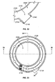
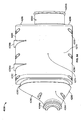
- a header 1010 is shown constructed in accordance with an exemplary embodiment of the present invention.
- the header 1010 is in fluid communication with a fluid circulation line 1012 of a recreational body of water, such as a swimming pool, spa, etc.
- a pump (not shown) is typically provided along the fluid circulation line 1012 for pumping water therethrough, and filter(s) and/or strainer(s) (not shown) are generally provided along the fluid circulation line 1012 for filtering/straining water upstream from the header 1010.
- the header 1010 is provided in fluid communication with a heat exchanger 1014, such as the sinusoidal fin-type heat exchanger disclosed in United States Patent No. 6,321,833 .
- a heat exchanger 1014 such as the sinusoidal fin-type heat exchanger disclosed in United States Patent No. 6,321,833 .
- An electrical control system 1016 is provided for managing activation and/or deactivation of the heat exchanger 1014 in accordance with sensed conditions, e.g., pressure and/or temperature, within the header 1010.
- Exemplary control systems may include programmed circuit boards and/or other electronic/electrical system(s). Also, it is contemplated that the electrical control systems can be structurally integrated with the heat exchanger 1010 and/or structural separate therefrom.
- exemplary water flow thereto and therefrom has been designated as follows: water flow from the fluid circulation line 1012 to an inflow side 1018 of the header 1010 has been designated as flow path F IN1 ; water flow from the inflow side 1018 to the heat exchanger 1014 has been designated as flow path F IN2 ; water flow from the heat exchanger 1014 to an outflow side 1020 of the header 1010 has been designated as flow path F OUT1 ; and water flow from the outflow side 1020 to the fluid circulation line 1012 has been designated as a flow path F OUT2 .
- the header 1010 facilitates bypass of the heat exchanger 1014, e.g. under high pressure conditions, and, to facilitate further consideration and discussion of same below, an exemplary bypass flow has been designated in FIG. 1 as flow path F B .
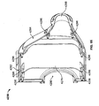
- the header 1010 includes a manifold 1022, a plurality of circulation line adapter assemblies 1024a, 1024b, a plurality of exchanger line adapter assemblies 1026a, 1026b, and a service cartridge assembly 1028.
- a manifold 1022 a plurality of circulation line adapter assemblies 1024a, 1024b, a plurality of exchanger line adapter assemblies 1026a, 1026b, and a service cartridge assembly 1028.
- Each of the manifold 1022, the circulation line adapter assemblies 1024a, 1024b, the exchanger line adapter assemblies 1026a, 1026b, and the service cartridge assembly 1028 shall be discussed below with further detail.
- the header 1010 includes a plurality of exchanger line adapter assemblies 1026 configured to channel fluid into said exchanger line inlet 1086 from a heat exchanger 1014 and to channel fluid out of said exchanger line outlet 1042 to the heat exchanger 1014.
- the manifold 1022 can be provided as an integrated one-piece structure, though, as discussed below in connection with the third aspect of the present invention, it is contemplated that a manifold can be formed of a plurality of components. As disclosed in United States Patent No. 6,026,804 , the manifold 1022 is preferably formed from plastic due to economy of materials and corrosion resistance.
- the header 1010 includes a lock ring 1150 configured to secure said service cartridge assembly 1028 within said manifold 1022.
- said frame 1140 is configured to mate with said manifold 1022 so as to inhibit rotational motion of said frame 1140.
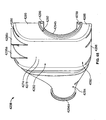
- the manifold 1022 includes a substantially cylindrical wall 1030 that extends about a central axis, referenced herein as an inflow axis A IN .
- a bypass opening 1032 is formed transversely in the substantially cylindrical wall 1030 in alignment with a midpoint of the inflow axis A IN .
- the bypass opening 1032 has a central axis, referenced herein as a bypass axis A B , which extends perpendicularly with respect to the inflow axis A IN .
- An inlet, referenced herein as a circulation line inlet 1034 is formed at an end of the substantially cylindrical wall 1030.
- the circulation line inlet 1034 defines therein a first inflow chamber 1036 and is provided with external threads 1038.
- An annular groove 1040. is formed within the circulation line inlet 1034 at a terminus thereof.
- An outlet referenced herein as an exchanger line outlet 1042, is formed at an end of the substantially cylindrical wall 1030 opposite the circulation line inlet 1034.
- the exchanger line outlet 1042 defines therein a second inflow chamber 1044 and is provided with an annular rim 1046 spaced from a terminus of the exchanger line outlet 1042 opposite the circulation line inlet 1034.
- a temperature sensor 1048 is preferably provided in fluid communication with the second inflow chamber 1044 and in electrical communication with the electrical control system 1016 of FIG. 1 .
- the temperature sensor 1048 is configured to sense a temperature of the water in the flow path F IN2 and send a corresponding temperature measurement to the electrical control system 1016. Should the water temperature along flow path F IN2 be lower than desired, the electrical control system 1016 will activate the heat exchanger 1014.
- the manifold 1022 preferably includes a substantially annular bypass port 1050 that extends from the substantially cylindrical wall 1030 about the bypass axis A B .
- the bypass port 1050 defines a chamber therein, which is referenced herein as a bypass chamber 1052, and which is in fluid communication with first and second inflow chambers 1036, 1044 via the bypass opening 1032.
- the bypass port 1050 has an inner radius, which is designated as radius R 1 in FIG. 6 . It is preferable that the radius R 1 be substantially similar, e.g., about equal, to a radius of the cylindrical wall 1030 (not designated) to increase potential flow along path F B .
- the bypass port 1050 preferably has a drain opening (not designated) formed therein that receives a drain plug 1054 for manual release of fluid from the bypass chamber 1052. Also, the bypass port 1050 preferably has an opening (not designated) formed therein for receiving a stop plug 1056. It is contemplated that a user of the header 1010 can replace the stop plug 1056 with a pressure relief valve for exhausting pressurized fluid from the bypass port 1050 that exceeds a set point of the pressure relief valve.
- the manifold 1022 includes an annular housing 1058 that is aligned with the bypass axis A B .
- the annular housing 1058 extends axially from the bypass port 1050 and, as further discussed below, is partially concentric therewith.
- the annular housing 1058 defines a chamber therein, which is referenced herein as a receiving area 1060 and which is sized and shaped to have the service cartridge assembly 1028 inserted therein.
- the receiving area 1060 has an inner radius, which is designated as radius R 2 in FIG. 6 , and which is greater than the inner radius R 1 of the bypass port 1050.
- a service opening 1062 is defined by the annular housing 1058 at an end thereof opposite the bypass port 1050, and the annular housing 1058 is provided with external threads 1064 proximal the service opening 1062.
- the annular housing 1058 has formed therein a plurality of openings, referenced herein as outflow openings 1066a, 1066b, which are partially aligned along an outflow axis A OUT perpendicular with respect to the bypass axis A B and parallel with respect to the inflow axis A IN .
- Each one of the outflow openings 1066a, 1066b is preferably circumferentially-spaced from each other one of the outflow openings 1066a, 1066b by about one-hundred and eighty degrees (180°).
- the annular housing 1058 is, as indicated above, partially concentric with the bypass port 1050.
- the annular housing 1058 and the bypass port 1050 form an annular channel 1068 therebetween, and the annular housing 1058 includes a tapered section 1070 that extends from the bypass port 1050 to enclose that side of the annular channel 1068 opposite the receiving area 1060.
- Circumferentially-displaced ribs which are referenced herein as manifold ribs 1072a, 1072b, are positioned within the annular channel 1068 and extend axially from the bypass port 1050 to the annular housing 1058 to assist in aligning the service cartridge assembly 1028 when same is inserted in the receiving area 1060.
- Each one of the manifold ribs 1072a, 1072b is preferably displaced by about one-hundred and eighty degrees (180°) from each other one of the plurality of manifold ribs 1072a, 1072b. Additional ribs can be provided in the annular channel 1068 to assist in aligning the service cartridge assembly 1028, such as that which is shown and designated as a positioning rib 1074 in FIG. 5 .
- Each one of the ribs 1072a, 1072b, 1074 preferably extends axially along the annular housing 1058 into the receiving area 1060.
- the annular channel 1068 and the ribs 1072a, 1072b, 1074 are sized and shaped to mate with the service cartridge assembly 1028 and inhibit rotation thereof.
- the bypass chamber 1052 of the bypass port 1050 is in fluid communication with the receiving area 1060 of the annular housing 1058 under certain pressure conditions.
- the manifold 1022 includes a circulation line outlet 1076 proximal the outflow opening 1066a, wherein the circulation line outlet 1076 is shown to be defined by a substantially annular wall extending from the annular housing 1058.
- the circulation line outlet 1076 defines therein a first outflow chamber 1078 and is provided with external threads 1080.
- An annular groove 1082 is formed within the circulation line outlet 1076 at a terminus thereof.
- a plurality of temperature sensors 1084a, 1084b are preferably provided in fluid communication with the first outflow chamber 1078 and in electrical communication with the electrical control system 1016 of FIG. 1 . (electrical connection path not shown).
- the temperature sensor 1084a for example, is configured to sense a temperature of the water in the flow path F OUT2 and send a corresponding temperature measurement to the electrical control system 1016.
- Temperature sensor 1084b is redundantly provided as a safety measure. Should the water temperature along flow path F OUT2 be sensed by temperature sensor 1084a and/or temperature sensor 1084b as being greater than desired, the electrical control system 1016 will deactivate the heat exchanger 1014 in response thereto.
- the manifold 1022 further includes an exchanger line inlet 1086 defined by a substantially annular wall extending from the annular housing 1058 proximal the outflow opening 1066b.
- the exchanger line inlet 1086 defines therein a second outflow chamber 1088 and is provided with an annular rim 1090 spaced from the terminus of the exchanger line inlet 1086 opposite the annular housing 1058.
- Each one of the exchanger line inlet 1086, the circulation line outlet 1076, the exchanger line outlet 1042, and the circulation line inlet 1034 preferably has a radius (not designated) substantially equal to that of each other one of the exchanger line inlet 1086, the circulation line outlet 1076, the exchanger line outlet 1042, and the circulation line inlet 1034
- the exchanger line inlet 1086 is slightly offset from the outflow axis A OUT .
- a port extends from the exchanger line inlet 1086 to define a chamber, referenced herein as an outflow sensing chamber 1094, that is in fluid communication with the second outflow chamber 1088.
- a pressure sensor referenced herein as an outflow pressure sensor 1096, extends into the outflow pressure port 1092 to measure the pressure P OUT of the water along the flow path F OUT1 .
- a port referenced herein as an inflow pressure port 1098, extends from the exchanger line outlet 1042 to define a chamber, referenced herein as an inflow sensing chamber 1100, that is in fluid communication with the second inflow chamber 1044.
- a pressure sensor referenced herein as an inflow pressure sensor 1102, extends into the inflow pressure port 1098 to measure a pressure PIN of the water along the flow path F IN2.
- the outflow pressure sensor 1096 and the inflow pressure sensor 1102 are utilized to have the electrical control system 1016 activate and/or deactivate the heat exchanger 1014 in accordance with a pressure differential ⁇ P, e.g., (PIN - P OUT ). This may be accomplished by any suitable electro-mechanical and/or electronic means known in the art.
- the outflow pressure sensor 1096 sends the pressure P OUT to the electrical control system 1016 and that the inflow pressure sensor 1102 sends the pressure PIN to the electrical control system 1016, wherein an electronic processor compares (differences) P IN and P OUT to obtain a pressure differential ⁇ P.
- the electronic processor retrieves a pressure set point P SP from memory associated therewith, and compares same with the pressure differential to identify if the set point has been reached/exceeded.
- the measuring and comparison can be done repetitively over time and, in the event that a rising pressure differential ⁇ P meets and/or exceeds the pressure set point P SP , the electrical control system 1016 initiates activation of the heat exchanger.
- the set point can be between about 0.1 pounds per square inch (PSI) and about 5.0 (PSI), and can also be between about 0.2 PSI and about 1.5 PSI. Notwithstanding, it is contemplated that any suitable set point can be provided.
- each one of the pressure sensors 1096, 1102 are components of a mechanical pressure differential switch (not shown) attached to the pressure ports 1092, 1098 to directly measure a difference in pressure between the two ports 1092, 1098. It is contemplated that each one of the sensors 1096, 1102 can include a movable diaphragm (not shown) responsive to the pressures of the sensing chambers 1094, 1100, and that a tube (not shown) can be provided to house both diaphragms A shaft (not shown) is secured to both diaphragms, and the diaphragms displace proportionally to the pressure at the respective ports 1092, 1098.
- the shaft is spring-loaded in such a manner that it may be calibrated to define a set-point for measuring a particular range of differential pressures.
- the shaft is connected to an electrical switch, such that the switch contacts are normally open, and the contacts are configured to close if the shaft is displaced an adequate distance relative to the set point of the spring. If both pressures are the same (the condition in which there is no water flow through the heat exchanger), the connecting shaft is stationary, and the switch contacts remain open. If the pressure at the inflow port 1098 is higher than the pressure at the outflow port 1092 by a predetermined amount, such as about 0.2 - 0.8 PSI in the first aspect of the present invention, then the switch contacts close to initiate activation of the heat exchanger 1014. If the pressure at the inflow port 1098 is less than the pressure at the outflow port 1092, such as in a reversed piping scenario, then the switch contacts remain open.
- the manifold 1022 includes a plurality of outwardly extending finger sets 1104 aligned along a shared plane.
- Each one of the finger sets 1104 includes a first finger (not designated), a second finger (not designated), and a passage (not designated) extending therebetween for receiving one of a plurality of bolts 1106 to secure the header 1010 to the heat exchanger 1014.
- Each one of the bolts 1106 can be provided with spacers and/or washers.
- the exemplary manifold 1022 includes eight finger sets 1104, wherein two finger sets 1104 extend perpendicularly from the inflow side 1018 proximal the exchanger line outlet 1042 in a first direction, two finger sets 1104 extend perpendicularly from the inflow side 1018 proximal the exchanger line outlet 1042 in a second direction opposite the first direction, two finger sets 1104 extend perpendicularly from the outflow side 1020 proximal the exchanger line inlet 1086 in the first direction, and two finger sets 1104 extend perpendicularly from the outflow side 1020 proximal the exchanger line inlet 1086 in the second direction.
- the circulation line adapter assemblies 1024a, 1024b of the header 1010 are releasably securable to the manifold 1022 at the circulation line outlet 1076 and the circulation line inlet 1034, respectively.
- the circulation line adapter assemblies 1024a, 1024b shall now be discussed with exemplary reference to the circulation line adapter assembly 1024a. It shall be clear to one skilled in the art that the below discussion of the circulation line adapter 1024a is equally applicable to the circulation line adapter 1024b.
- the circulation line adapter assembly 1024a has a seal 1108a, a circulation line fitting 1110a, and a lock ring 1112a.
- the seal 1108a which is preferably formed from an elastomeric material, is positioned within the annular groove 1082 and extends radially therefrom.
- the line fitting 1110a which is preferably formed from a plastic material, includes an annular wall 1114a extending about the outflow axis A OUT .
- the line fitting 1110a further includes a flange 1116a that extends radially from an end of the annular wall 1114a and that abuts the seal 1108a.
- the inner radius (not designated) of the annular wall 1114a is substantially equal to the inner radius (not designated) of the circulation line outlet 1076, though the outer radius (not designated) of the annular wall 1114a is less than the outer radius (not designated) of the circulation line outlet 1076.
- the lock ring 1112a includes a radially extending section 1118a and an internally-threaded section 1120a depending therefrom, such that the annular wall 1114a extends through the radially extending section 1118a of the lock ring 1112a, and such that the external threads 1080 of the circulation line outlet 1076 cooperate with the internally-threaded section 1120a of the lock ring 1112a to secure the line fitting 1098a against the circulation line outlet 1076.
- the circulation line adapter assembly 1024b includes a seal 1108b, a circulation line fitting 1110b, and a lock ring 1112b.
- the seal 1108b is positioned within the annular groove 1040 and extends radially therefrom.
- the line fitting 1110b includes an annular wall 1114b extending about the inflow axis A IN and further includes a flange 1116b abutting the seal 1108b.
- the lock ring 1112b includes a radially extending section 1118b and an internally-threaded section 1120b depending therefrom, such that the annular wall 1114b extends through the radially extending section 1118a of the lock ring 1112b, and such that the external threads 1038 of the circulation line inlet 1034 cooperate with the internally-threaded. section 1120b of the lock ring 1112b to secure the line fitting 1110b against the circulation line inlet 1034.
- the exchanger line adapter assemblies 1026a, 1026b of the header 1010 are releasably securable to the manifold 1022 at the exchanger line inlet 1086 and the exchanger line outlet 1042, respectively.
- the exchanger line adapter assemblies 1026a, 1026b include O-rings 1122a, 1122b, respectively, and bases 1124a, 1124b, respectively.
- exchanger line adapter assemblies 1026a, 1026b shall now be discussed with exemplary reference to the exchanger line adapter assembly 1026a. It shall be clear to one skilled in the art that the below discussion of the exchanger line adapter assembly 1026a is equally applicable to the exchanger line adapter assembly 1026b.
- the O-ring 1122a which is preferably formed from an elastomeric material, such as rubber, extends circumferentially about the exchanger line inlet 1086.
- the base 1122a which is preferably formed from plastic, includes a tiered-section 1126a having a first depression area 1128a with a first diameter (not designated) and a second depression area 1130a with a second diameter less than the first diameter (not designated).
- a surface, referenced herein as a seat 1132a extends across a terminus of the second depression area 1130a. opposite the first depression area 1128a.
- a plurality of openings, referenced herein as exchanger ports 1134a are formed in the seat 1132a and each one of a plurality of conduits 1136a extend from one of the plurality of exchanger ports 1134a.
- the base 1124a has a plurality of boreholes 1138a formed therein for receiving bolts 1106 extending from the manifold 1022 to securingly retain the base 1124a against the manifold 1022.
- the first depression area 1128a receives the annular rim 1090 and the O-ring 1122a, while the area extending therefrom to the terminus of the exchanger line inlet 1086 is received by the second depression area 1130a and abuts the seat 1132a.
- the service cartridge assembly 1028 which includes a frame 1140, a handle 1142, a plurality of O-rings 1144, and a flapper valve 1146, is positioned within the receiving area 1060 of the annular housing 1058.
- the service cartridge assembly 1028 defines therein a third outflow chamber 1148.
- An internally-threaded lock ring 1150 cooperates with the external threads 1064 proximal the service opening 1062 to inhibit inadvertent removal of the service cartridge assembly 1028 therethrough.
- the lock ring 1150 is disengaged from the external threads 1064 of the service opening 1062, the service cartridge assembly 1028 is removable for servicing and/or replacement of the service cartridge assembly 1028 and/or the components thereof, e.g., the flapper valve 1146, etc.
- the frame 1142 of the service cartridge assembly 1028 includes a circular wall 1152 aligned along the bypass axis A B , and the handle 1142 extends from the circular wall 1152 in a direction opposite the receiving area 1060.
- the frame 1142 further includes a grooved annulus 1154 extending perpendicularly from the circular wall 1152 into the receiving area 1060.
- the outer-radius of the grooved annulus 1154 is just less than the inner radius R 2 of the annular housing 1058, and each one of the plurality of O-rings 1144 are positioned within each one of the annular grooves (not designated) of the grooved annulus 1154.
- a plurality of ribs which are referenced herein as cartridge ribs 1156, are circumferentially displaced along a side of the grooved annulus 1154 opposite the handle 1142 and extend perpendicularly from the grooved annulus 1154.
- a generally cylindrical wall is provided with a slight tapering, which is referenced herein as a tapered wall 1158.
- the tapered wall 1158 is at least partially bound by the cartridge ribs 1156 and extends from the grooved annulus 1154 to an annular lip 1160 defining a third opening in the frame 1142, referenced has a valve opening (not designated).
- the tapered wall 1158 is tapered toward the grooved annulus, such that the tapered wall 1158 has a greater outer radius proximal the annular lip 1160 and a lesser outer radius proximal the grooved annulus 1154.
- a first hole 1162a is formed in the tapered wall 1158 proximal the outflow opening 1066a in the manifold 1022, such that the third outflow chamber 1148 is in fluid communication with the first outflow chamber 1078 of the circulation line outlet 1076.
- a second hole 1162b is formed in the tapered wall 1158 proximal the outflow opening 1066b in the manifold 1022, such that the third outflow chamber 1148 is in fluid communication with the second outflow chamber 1088 of the exchanger line inlet 1086.
- the tapered wall 1158 has a plurality of rectangular channels 1164a, 1164b formed therein that extend from the annular lip 1160 to the first and second holes 1162a, 1162b, respectively.
- the rectangular channels 1164a, 1164b are preferably circumferentially-displaced about the tapered wall 1158 by about one hundred and eighty degrees (180°). As will be discussed with further detail below, the rectangular channels 1164a, 1164b assist in securing the flapper valve 1146 to the frame 1140.
- a notched flange 1166 extends axially from an inner circumference of the annular lip 1160 and mates with the annular channel 1068 formed at the juncture of the housing 1058 and the bypass port 1050. More particularly, the notched flange 1166 includes a plurality of notches 1168a, 1168b that extend through the annular lip 1160 and that are sized and dimensioned to mate with the manifold ribs 1072a, 1072b to inhibit rotation of the service cartridge assembly 1028.
- the notches 1168a, 1168b are preferably circumferentially-displaced by about one hundred and eighty degrees (180°) to correspond with the manifold ribs 1072a, 1072b.
- the notched flange 1166 preferably further includes a positioning notch 1170 mating with the positioning rib 1074.
- the positioning notch 1170 and the positioning rib 1074 cooperate to ensure that the service cartridge assembly 1028 has been inserted into the receiving area 1060 in the desired spatial orientation.
- a shoulder 1172a is formed in the tapered wall 1158 adjacent the notch 1168a and proximal the annular lip 1160.
- a shoulder 1172b is formed in the tapered wall 1158 adjacent the notch 1168b and proximal the annular lip 1160.
- Each one of the shoulders 1172a, 1172b is preferably circumferentially-displaced about the tapered wall 1158 from each other one of the shoulders 1172a, 1172b by about one hundred and eighty degrees (180°).
- each one of the shoulders 1172a, 1172b is preferably circumferentially-displaced about the tapered wall 1158 from each one of the rectangular channels 1164a, 1164b adjacent thereto by about ninety degrees (90°).
- the shoulders 1172a, 1172b assist in securing the flapper valve 1146 to the frame 1140.
- the flapper valve 1146 preferably includes a shaft 1174, a torsion spring 1176, and a plurality of hinged pieces, which are referenced herein as flappers 1178a, 1178b.
- the flappers 1178a, 1178b shall be discussed with exemplary reference to the flapper 1178a. It shall be clear to one skilled in the art, however, that discussion below of the flapper 1178a is equally applicable to the flapper 1178b.
- the flapper 1178a which can be formed from polypropylene, includes a semicircular portion 1180 and a plurality of hinges 1182a, 1182b extending from the semicircular portion 1180. Each one of the hinges has formed in a first side thereof a first U-shaped channel (not designated) and, in a second side opposite the first side; a second U-shaped channel (not designated) that is inverted with respect to the first U-shaped channel.
- the shaft 1174 extends through the hinges 1182a, 1182b and extends through a central space (not designated) of the torsion spring 1176.
- the shaft has a first end 1184a positioned within the shoulder 1172a of the frame 1140 and a second end 1184b positioned within the shoulder 1174b of the frame 1140.
- the manifold ribs 1072, 1072b of the housing 1058 extend into the notches 1168a, 1168b, which thereby secures the ends 1184a, 1184b in the shoulders 1174a, 1174b, respectively.
- the shaft is preferably formed from type-316 stainless steel.
- the torsion spring 1176 is preferably formed from type-316 stainless steel spring wire.
- the flapper 1178a includes a first side 1186 facing the bypass chamber 1052, a second side 1188 facing the third outflow chamber 1148, a straight edge 1190 that is substantially parallel with respect to the shaft 1174, and a curved edge 1192 that is proximal the frame 1140.
- the flapper 1178a further includes a curved extension 1194 extending from the first side 1186 at the straight edge 1190.
- the curved extension 1194 of the flapper 1178a and the curved extension 1194 of the flapper 1178b cooperate to receive the torsion spring 1176.
- the flapper 1178a preferably includes a stop 1196 and a stop surface 1198 complementary thereto, such that, when the flapper valve 1146 is in the closed position, the stop 1196 of the flapper 1178a abuts the stop surface 1198 of the flapper 1178b and the stop 1196 of the flapper 1178b abuts the stop surface 1198 of the flapper 1178 to inhibit reverse rotation of the flappers 1178a, 1178b.
- the flapper 1178a includes a protrusion 1200 extending from the second side 1188 that is aligned with an imaginary bisector thereof.
- the protrusion 1200 includes a beveled edge (not designated), such that the beveled edges of the flappers 1178a, 1178b make contact at a fully-open position of the flapper valve 1146.
- the protrusion 1200 begins proximal the straight edge 1190 and extends past the boundary of the curved edge 1192, such that an end of the protrusion 1200, referenced herein as the protrusion end 1202, is spaced apart from the semicircular portion 1180.
- the protrusion end 1202 of the flapper 1178a is positioned within the rectangular channel 1164a of the frame 1140 and the protrusion end 1202 of the flapper 1178a is positioned within the rectangular channel 1164b.
- the torsion spring 1176 has a rotational force applied to the flappers 1178a, 1178b, such that the protrusion end 1202 of each one of the flappers is secured within the corresponding one of the channels 1164a, 1164b.
- FIGS. 1 , 6 , 12 , 13 , and 15 which show the flapper valve 1146 in a closed position
- the flapper 1178a is angularly displaced from the flapper 1178b by about one-hundred and eighty degrees (180°), thereby obstructing fluid flow from the bypass chamber 1052 to the third outflow chamber 1148 along the flow path F B .
- the flapper 1178a when a high-pressure condition exists in the bypass chamber 1052, the flapper 1178a is angularly displaced, thereby permitting fluid flow from the bypass chamber 1052 to flow to the third outflow chamber 1148 along the flow path F B .
- the flapper 1178b In the open positions, the flapper 1178b is angularly displaced from the closed position by as much as an angle ⁇ 1 , which is preferably about fifty degrees (50°), and the flapper 1178a is angularly displaced from the closed position by an angle ⁇ 2 , which is preferably also about fifty degrees (50°), for a preferred maximum displacement of two-hundred and eighty-degrees (280°).
- an angle ⁇ 1 which is preferably about fifty degrees (50°)
- the flapper 1178a is angularly displaced from the closed position by an angle ⁇ 2 , which is preferably also about fifty degrees (50°), for a preferred maximum displacement of two-hundred and eighty-degrees (280°
- the flapper valve 1146 is releasably securable to the frame 1140.
- the service cartridge assembly 1028 is removed therefrom by a user, who then rotates the flapper valve 1146 into an open position, such that the protuberance ends 1202 have moved out of the channels 1164a, 1164b, through the holes 1162a, 1162b, and into the third inflow chamber 1148.
- the flapper valve 1146 is then pulled in a direction opposite the circular wall 1152 through the valve opening defined by the annular lip 1160 of the frame 1140.
- a user rotates the flapper valve 1146 into an open position, inserts the shaft ends 1184a, 1184b into the shoulders 1172a, 1172b and then releases the flapper valve 1146, allowing the protuberance ends 1202 to move in response to the force of the torsion spring 1176 into the channels 1164a, 1164b.
- the total angular displacement between the flappers 1178a, 1178b is a function of the water flow rate on flow paths F IN1 and/or F IN2 .
- the flapper valve 1146 opens proportionally to allow more water to bypass those heat exchanger tubes proximal the exchanger line outlet 1042, keeping the water flow rate through the heat exchanger 1010 at the optimum flow rate.
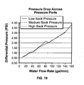
- exemplary embodiments of the header 1010 provide enhanced optimization of water flow rate through the heat exchanger 1014 and minimize the differential pressure, also known as "pressure drop", across the heat exchanger 1014.
- pressure drop also known as "pressure drop”
- the header 1010 enables a higher total water flow rate in a pool and/or spa system to be provided with a smaller circulation pump. Furthermore, as shown in FIG.
- the differential pressure appears to have minimal deviation when the "back pressure" (pressure in the bypass chamber 1052) varies from a low pressure, such as about two (2) PSI, to a medium pressure, such as about ten (10) PSI , and to a high pressure, such as about forty (40) PSI.
- a low pressure such as about two (2) PSI
- a medium pressure such as about ten (10) PSI
- a high pressure such as about forty (40) PSI.
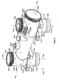
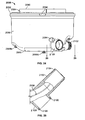
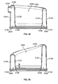
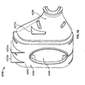
- FIG. 20 a top plan view of a heating unit 2010 is shown.
- the heating unit 2010 is in fluid communication with a fluid circulation line (not shown in FIG. 20 ) of a recreational body of water, such as a swimming pool, spa, etc.
- a pump (not shown) is typically provided along the fluid circulation line for pumping water therethrough, and filter(s) and/or strainer(s) (not shown) are provided along the fluid circulation line for filtering/straining water upstream from the heating unit 2010.
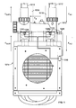
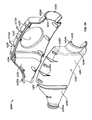
- the heating unit 2010 includes an enclosed cabinet 2012, which has a base plate 2014, a cylindrical cabinet side wall 2016, and a cover 2018 that is shown in FIG. 20 to have been removed to reveal a cabinet space (not designated) defined within the cabinet 2012.
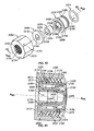
- a tube-in-tube heat exchanger 2020 constructed in accordance with an exemplary embodiment of the present invention is shown to be positioned within the space of the cabinet 2012 and fastened to the base plate 2014 and, for the purposes of clarity of disclosure, is referenced herein as the tube-in-tube heat exchanger 2020.
- the tube-in-tube heat exchanger 2020 includes a water outlet nipple 2022 and a water inlet nipple 2024 that each extend through the cabinet side wall 2016 to facilitate attachment thereof to the fluid circulation line without removal of the cover 2018 being required.
- the tube-in-tube heat exchanger 2020 defines an external cavity 2026 in which a compressor 2028 is shown to be positioned.
- a plurality of external tube extensions 2030a, 2030b can be provided between the tube-in-tube heat exchanger 2020 and the compressor 2028 for fluid communication therebetween of refrigerant. Additional components of the heating unit 2010 for use in the heat cycle can be in communication with the extensions 2030a, 2030b.
- the tube-in-tube heat exchanger 2020 is adapted to have water flow therethrough from the water inlet nipple 2024 to the water outlet nipple 2022, during which time heat is transferred, such as from the refrigerant to the water. Also discussed below, the position of the compressor 2028 within the external cavity 2026 reduces the amount of sound from the compressor 2028 that is perceptible by a user of the tube-in-tube heat exchanger 2020, e.g., the amplitude of compressor noise escaping the tube-in-tube heat exchanger 2020 is minimized.
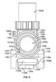
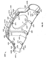
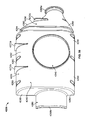
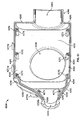
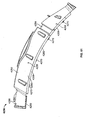
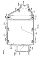
- the tube-in-tube heat exchanger 2020 includes a, tank 2032 that defines an annular chamber 2034 extending about a central axis AT and that further defines the external cavity 2026 along the central axis AT.
- the tank 2032 includes an upper tank portion 2036, a lower tank portion 2038 electromagnetically welded thereto, and a plurality of ribbon seals 2040a, 2040b positioned between the upper tank portion 2036 and the lower tank portion 2038.
- a plurality of legs 2042a-c are provided for supporting the tank 2032.
- the legs 2042a-c can be used in combination with screws 2044a-c for removably securing the tank 2032 to the base plate 2014 of the heating unit 2010.
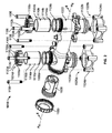
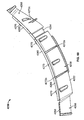
- the tube-in-tube heat exchanger 2020 includes a tube-in-tube assembly 2046 that has a spiral shape and that is positioned within the annular chamber 2034 of the tank 2032 to extend helically about the axis AT.
- the external cavity 2026 extends in an axial direction and through the tube-in-tube-assembly 2046.
- the tube-in-tube assembly 2046 includes a water hose 2048 and a refrigerant tube 2050 extending therethrough.
- the refrigerant tube 2050 is preferably formed from titanium and is adapted for having refrigerant flow therethrough.
- the water hose 2048 terminates at ends thereof that are referenced herein as water hose ends 2052a, 2052b.
- the refrigerant tube 2050 extends out past the water hose ends 2052a, 2052b and terminates outside the water hose 2048 at ends that are referenced herein as refrigerant tube ends 2054a, 2054b.
- Lock rings 2056a, 2056b secure the refrigerant tube ends 2054a, 2054b, respectively, to the external tube extensions 2030a, 2030b, respectively, for fluid communication of the refrigerant between the refrigerant tube 2050 and the compressor 2028.
- a primary water passage 2058 is defined by an annular space formed between the water hose 2048 and the refrigerant tube 2050.
- the primary water passage 2058 is in fluid communication with the water outlet nipple 2022 and the water inlet nipple 2024, which are provided with O-rings referenced herein as ring seals 2060a, 2060b.
- the water inlet nipple 2024 and the water outlet nipple 2022 are adapted for fluid communication with the fluid circulation line of the recreational body of water, e.g., swimming pool, spa, etc., to receive water to be heated in the primary water passage 2058 by the refrigerant tube 2050 and to provide water that has been heated by the refrigerant tube 2050, respectively.
- the water inlet nipple 2024 is provided with a temperature sensor 2062, a mounting strap 2064 therefor, a drain plug 2066, and a drain plug seal 2068. Also, a water diverter 2070 is positioned within the annular chamber 2034 adjacent the water inlet nipple 2024. The water diverter 2070 is sized and shaped to direct principal water flow to the primary water passage 2058 (and, in the second aspect of the present invention, is loosely fitted against the tank 2032 to facilitate a secondary "leakage flow" of water outside of the primary water passage 2058 for upward flow through the annular chamber 2034).
- a plurality of seal assemblies 2072a, 2072b are provided for sealing the refrigerant tube ends 2054a, 2054b, such that water is inhibited from escaping the tank 2032 at the seal assemblies 2072a, 2072b.
- Each one of the seal assemblies 2072a, 2072b includes an O-ring 2074, a piston 2076, a grommet 2078, a cap 2080, and a compression nut 2082, which shall each be discussed in further detail below with principal reference to FIGS. 41-44 .
- the tank 2032 includes a lower tank portion 2038 and an upper tank portion 2036 electromagnetically welded therewith.
- both the lower tank portion 2038 and the upper tank portion 2036 include an inner wall portion (designated below as portions 2084, 2122) that cooperate to define an inner wall of the tank 2032 through which the external cavity 2026 extends.
- both the lower tank portion 2038 and the upper tank portion 2036 include an outer wall portion (designated below as portions 2086, 2124) that cooperate to define an outer wall of the tank 2032.
- Said inner wall can be a cylindrical wall.
- the lower tank portion 2038 includes at least one inner wall portion 2084 extending about the axis AT to define a portion of the external cavity 2026 and at least one outer wall portion 2086 extending about the axis AT, such that the inner wall portion 2084 and the outer wall portion 2086 define therebetween a portion of the annular chamber 2034.
- the lower tank portion 2038 further includes a bottom wall 2088 extending from the inner wall portion 2084 to the outer wall portion 2086 to at least partially enclose the annular chamber 2034.
- the inner wall portion 2084 of the lower tank portion 2038 terminates at an end opposite the bottom wall 2088 with a first annular finger set 2090 having a first pair of annular fingers that define a first annular space therebetween.
- the outer wall portion 2086 of the lower tank portion 2038 terminates at an end opposite the bottom wall 2088 with a second annular finger set 2092 having a second pair of annular fingers that define a second annular space therebetween.
- the first and second annular finger sets 2090, 2092 mate with the upper tank portion 2036 to securingly align the lower tank portion 2038 thereto during electromagnetic welding of the tank portions 2036, 2038 to one another.
- the outer wall portion 2086 has a first elevation E 1 and the inner wall portion 2084 has a second elevation E 2 greater than the first elevation E 1 .
- an imaginary geometric plane aligned with the annular finger set 2092 has been designated in FIG. 27 as plane H O for the purpose of showing that the distance between the plane H O and the bottom wall 2088 is preferably multiform.
- the bottom wall 2088 is preferably inclined such that the distance from the finger set 2092 to the bottom wall 2088 increases between from the distance H 1 to the distance H 2 .
- the lower tank portion 2038 includes a drain opening 2094, an alignment tab 2096, and a plurality of shaped posts 2098a-c.
- the drain opening 2094 extends from the outer wall portion 2086 of the lower tank portion 2038 and is preferably plugged with a removable drain plug (not shown).
- the alignment tab 2096 is positioned along the outer wall portion 2086 of the lower tank portion 2038 proximal the finger set 2092 for securingly aligning the upper tank portion 2036 with the lower tank portion 2038 during attachment of the upper tank portion 2036 thereto, such as by electromagnetic welding.
- the shaped posts 2098a-c are provided for engaging the legs 2042a-c and shall be discussed with further detail below in connection with the legs 2042a-c.
- the lower tank portion 2038 has formed therein a plurality of passages, including a water inlet passage 2100 and a refrigerant tube outlet 2102.
- Each of the water inlet passage 2100 and the refrigerant tube outlet 2102 extend from the outer wall portion 2086 proximal the bottom wall 2088.
- the refrigerant tube outlet 2102 has external threads 2104 for engagement with the seal assembly 2072b.
- the water inlet passage 2100 preferably extends about ninety degrees with respect to the refrigerant tube outlet 2102.
- the water inlet passage 2100 has an annular groove 2106 formed at an end thereof for receiving the ring seal 2060b and is further discussed below in connection with the water inlet nipple 2024.
- the annular chamber 2034 includes an area proximal the water inlet passage 2100 that is referenced herein as a water diversion area 2108.
- the water diversion area 2108 is a space defined by the diverter 2070 of FIGS. 22 , 23 , and 30 .
- the diverter 2070 forms a loose seal with the outer wall portion 2086 to channel a principal flow of water from the water inlet passage 2100 into the primary water passage 2058 while allowing a desired amount of leakage flow of water into that area of the annular chamber 2034 outside the water diversion area 2108.
- the diverter 2070 can be configured to sit atop the bottom wall 2088 of the lower tank portion 2038 within the annular chamber 2034.
- the diverter 2070 includes a first retaining wall 2110 having an opening 2112 formed therethrough.
- the water hose 2048 which is preferably corrugated, extends through the opening 2112, such that the water hose end 2052a is securingly retained by the first retaining wall 2110.
- the refrigerant tube 2050 extends through the water diversion area 2108, and the diverter 2070 includes a second retaining wall 2114 defining an opening 2116 through which the refrigerant tube end 2054b extends.
- the diverter 2070 further includes a plurality of walls 2118a-c that extend between the first and second retaining walls 2110, 2114 and cooperate with the first and second retaining walls 2110, 2114 and the outer wall portion 2086 to at least partially enclose the diversion area 2108.
- the walls 2110, 2114, 2118a, 2118b, and 2118c can form a loose seal with the bottom wall 2088 and/or the outer wall portion 2086, such that water flowing into the diversion area 2070 from the water inlet passage 2100 is principally channeled into the primary water passage 2058 at the water hose end 2052a.
- the loose seal allows a secondary, leakage flow of water flow into that portion of the annular chamber 2034 outside of the diverter 2070, such that the annular chamber 2034 fills with water to the top of the upper tank portion 2036 of the tank 2032.
- leakage flow from the diverter 2070 into the annular chamber 2034 generally can be utilized to bypass the primary water passage 2058 when the pressure and/or water flow rate is undesirably high.
- the water outside the water hose 2048 in the annular chamber 2034 absorbs that heat escaping through the wall of the hose 2048 from that water in the primary water passage 2058.
- the diverter 2070 includes a hook 2120 for securing the diverter 2070 at an eyehole (not shown) formed in the lower tank portion 2038 to inhibit the diverter 2070 from floating to the top of the annular chamber 2034 and/or other motion causes by the water within the annular chamber 2034.
- the tube-in-tube heat exchanger 2020 can utilize any diverter, including, but not limited to, the diverter 4234 of FIGS. 51-68 described below in connection with the third aspect of the present invention.
- the upper tank portion 2036 includes at least one inner wall portion 2122 extending about the axis A T to define a portion of the external cavity 2026 extending along the axis AT.
- the upper tank portion 2036 further includes at least one outer wall portion 2124 extending about the axis AT, such that the inner wall portion 2122 and the outer wall portion 2124 define therebetween a portion of the annular chamber 2034 therebetween.
- the upper tank portion 2036 has a top wall 2126 that is opposite the bottom wall 2088 of the lower tank portion 2038 and that extends from the inner wall portion 2122 of the upper tank portion 2036 to the outer wall portion 2124 of the upper tank portion 2036 to at least partially enclose the annular chamber 2034.
- each one of the inner and outer wall portions 2122, 2124 of the upper tank portion 2036 (and the inner and outer wall portions 2084, 2086 of the lower tank portion 2038) can have a cylindrical shape.
- the upper tank portion 2036 is securingly aligned with the lower tank portion 2038. More particularly, the inner wall portion 2122 of the upper tank portion 2036 terminates at an end opposite the top wall 2126 of the upper tank portion 2036 with a first annular flange 2128. The first annular flange 2128 of the upper tank portion 2036 mates with the first annular finger set 2090 of the lower tank portion 2038, and the ribbon seal 2040b is positioned between the first annular flange 2128 and the first annular finger set 2090. Also, the outer wall portion 2124 of the upper tank portion 2036 terminates at an end opposite the top wall 2126 of the upper tank portion 2036 with a second annular flange 2130.
- the second annular flange 2130 of the upper tank portion 2036 mates with the second annular finger set 2092 of the lower tank portion 2038, and the ribbon seal 2040a is positioned between the second annular flange 2130 and the second annular finger set 2092.
- the upper tank portion 2036 is provided with an alignment tab 2132 that engages the alignment tab 2096 of the lower tank portion 2038 to secure the upper tank portion 2036 thereto.
- the upper tank portion 2036 has formed therein a plurality of passages, including a water outlet passage 2134 and a refrigerant tube inlet 2136.
- Each of the water outlet passage 2134 and the refrigerant tube inlet 2136 extend from the outer wall portion 2124 of the upper tank portion 2036 and proximal the top wall 2126 thereof.
- the refrigerant tube inlet 2136 has external threads 2138 for engagement with the seal assembly 2072a as further discussed below with reference to FIG. 44 .
- the water outlet passage 2134 has an annular groove 2140 formed at an end thereof for receiving the ring seal 2060a and is further discussed below in connection with the water outlet nipple 2022.
- the alignment tabs 2096, 2132 cooperate with one another to securingly align the upper and lower tank portions 2036, 2038, such that the water outlet passage 2134 of the upper tank portion 2036 extends parallel with respect to the water inlet passage 2100 of the lower tank portion 2038.
- the annular chamber 2034 includes an area proximal the water outlet passage 2134 that, for the purposes of those embodiments of second aspect of the present invention having the diverter 2070, is referenced herein as a water convergence area 2142.
- a water convergence area 2142 As best shown in FIG. 22 , an "open area,” e.g., the water convergence area 2142, is provided where the refrigerant tube end 2054a extends past the water hose end 2052b.
- the "open area" discussed above enables the flow of water from the water hose end 2052b of the primary water passage 2058 to fill those areas of annular chamber 2034 of the tank 2032 external of the tube-in-tube assembly 2046.
- the water outlet nipple 2022 includes a generally cylindrical wall 2144a with a tank attachment end 2146a and a line attachment end 2148a opposite the tank attachment end 2146a.
- the tank attachment end 2146a includes an annular flange 2150a that mates with the annular groove 2140 of the water outlet passage 2134 of the upper tank portion 2036.
- the ring seal 2060b is positioned between the annular groove 2140 and the annular flange 2150a.
- the line attachment end 2148a has an annular groove 2152a formed therein and external threads 2154a for coupling the water outlet nipple 2022 to that portion of the fluid circulation line (not shown) of the recreational body of water that is downstream of the tube-in-tube heat exchanger 2020.
- the line attachment end 2148a can be provided with any additional and/or alternative structure suitable for coupling the water outlet nipple 2022 to the fluid circulation line.
- the water inlet nipple 2024 is similar in some respect to the water outlet nipple 2022.
- the water outlet nipple 2024 includes a generally cylindrical wall 2144b with a tank attachment end 2146b and a line attachment end 2148b opposite thereto.
- the tank attachment end 2146b includes an annular flange 2150b that mates with the annular groove 2106 of the water inlet passage 2100 of the lower tank portion 2038, and the ring seal 2060a is positioned between the annular groove 2106 and the annular flange 2150b.
- the line attachment end 2148b has an annular groove 2152b formed therein and external threads 2154b for coupling the water inlet nipple 2024 to that portion of the fluid circulation line (not shown) of the recreational body of water that is upstream of the tube-in-tube heat exchanger 2020.
- the line attachment end 2148b can be provided with any additional and/or alternative structure suitable for coupling the water inlet nipple 2024 to the fluid circulation line.
- the water inlet nipple 2024 can advantageously be provided with other features.
- the exemplary water inlet nipple 2024 has a first passage 2156 formed therein for receiving the temperature sensor 2062, such that the first passage 2156 is in fluid communication with water flowing through the cylindrical wall 2144b for sensing the temperature of such water.
- a plurality of annular bosses 2158 are formed on the outer surface of the cylindrical wall 2144b for securingly aligning the mounting strap 2064 that is used to removably secure the temperature sensor 2062 to the water inlet nipple 2024.
- the exemplary water inlet nipple 2024 has a second passage 2160 formed therein for receiving the drain plug 2066, such that the second passage 2160 is in fluid communication with water flowing through the cylindrical wall 2144b for drainage thereof.
- a depression 2162 having a radius greater than that of the second passage 2160 is provided in alignment therewith for receiving the drain plug seal 2068.
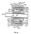
- the refrigerant tube 2050 includes the refrigerant tube ends 2054a, 2054b and a refrigerant tube body 2164 extending therebetween.
- the refrigerant tube body 2164 preferably has a spiraled outer surface for inducing turbulent flow of water in the primary water passage 2058, thereby facilitating more efficient heat transfer.
- the refrigerant tube ends 2054a, 2054b preferably have substantially cylindrical outer surfaces to be received by the seal assemblies 2072a, 2072b, respectively.
- seal assemblies 2072a, 2072b (and the refrigerant tube ends 2054a, 2054b) shall now be made with respect to the seal assembly 2072a (and the refrigerant tube end 2054a), and it shall be understood that such discussion is similarly applicable with respect to the seal assembly 2072b (and the refrigerant tube end 2054b).
- the seal assembly 2072a includes the O-ring 2074, the piston 2076, the grommet 2078, the cap 2080, and the compression nut 2082.
- the seal assembly 2072a further includes a continuous cylindrical opening 2166 extending through the O-ring 2074, the piston 2076, the grommet 2078, the cap 2080, and the compression nut 2082 along a central axis, referenced herein as axis A SA .
- the continuous cylindrical opening 2166 has a radius just greater than that of the refrigerant tube end 2054a, such that the refrigerant tube end 2054a extends through and out of the continuous opening 2166 (see FIG. 44 ).
- the seal assembly 2072a is operable between a relaxed state and a compressed state, in which the cap 2080 cooperates with the piston 2076 to compress the grommet 2078 when the compression nut 2082 has engaged the external threads 2138 of the refrigerant tube inlet 2136.
- the compression, nut 2082 includes an open end 2168 and a cylindrical, internally-threaded wall 2170 for respectively receiving the refrigerant tube inlet 2136 into an internal chamber 2172 of the nut 2082 and mating with the external threads 2138 thereof.
- the compression nut 2082 further includes a flat annular wall 2174 opposite the open end 2168 extending radially inward from the internally-threaded wall 2170 of the compression nut 2082.
- An opening 2176 extends through the flat annular wall 2174 along the axis A SA .
- the O-ring 2074, the piston 2076, the grommet 2078, and the cap 2080 are each received into the internal chamber 2172 of the nut 2082.
- the piston 2076 is positioned proximal the refrigerant tube inlet 2136 (or, in the case of the seal assembly 2072b, the refrigerant tube outlet 2102) and is received by the compression nut 2082.
- the piston 2076 includes an annular piston wall 2178 that defines that portion of the continuous opening 2166 extending through the piston 2076 and further includes a tapered section 2180 that tapers in a direction toward the refrigerant tube inlet 2136 (or, in the case of the seal assembly 2072b, the refrigerant tube outlet 2102).
- the annular piston wall 2178 has a first portion 2182 with a first inner radius that is just greater than that the refrigerant tube ends 2054a, 2054b and a second portion 2184 with a second inner radius that is greater than the first inner radius, such that the second portion 2184 is widened to receive the grommet 2078 for seating thereof at the tapered section 2180.
- An annular rim 2186 extends radially outward from the tapered section 2180 and terminates at a position adjacent the internally-threaded wall 2170.
- the piston 2076 includes an annularly grooved flange 2188 that extends from the rim 2186 concentrically with respect to the first portion 2182 of the annular piston wall 2178.
- the annularly grooved flange 2188 receives in a groove 2190 thereof the O-ring 2074, such that the O-ring 2074 is spaced apart from the internally-threaded wall 2170 of the compression nut 2082.
- the grooved flange 2188 and the first portion 2182 of the annular piston wall 2178 define a first annular space 2192 therebetween, which is further discussed below.
- the piston 2076 further includes a lipped flange 2194 having a flange 2196 that extends from the rim 2186 substantially concentrical with respect to the second portion 2184 of the annular piston wall 2178 and that, together with the second portion 2184 of the piston wall 2178, defines a second annular space 2198.
- the walls of the piston 2076 are of substantially equal thickness to minimize warping, including, for example, the flange 2196, the second portion 2184 of the piston wall 2178, the grooved flange 2188, and the first portion 2182 of the piston wall 2178.
- the first and second annular spaces 2192, 2198 are sized and dimensioned for such purposes.
- the flange 2196 terminates at an end opposite the rim 2186 with a piston lip 2200 that extends radially toward the internally-threaded wall 2170 of the compression nut 2082, such that the lipped flange 2194 and the annularly-grooved flange 2188 of the piston 2076 cooperate with the internally-threaded wall 2170 of the compression nut 2082 to define an annular space, herein referenced as a receiving area 2202, for receiving the external threads 2138 of the refrigerant tube inlet 2136 (or, in the case of the seal assembly 2072b, the external threads 2104 of the refrigerant tube outlet 2102).
- the grommet 2078 is formed of a resiliently deformable material, such as rubber.
- the grommet 2078 includes a substantially cylindrical grommet body 2204 defining therein a portion of the continuous opening 2166 having a radius just greater than each of the refrigerant tube ends 2054a, 2054b.
- the grommet 2078 further includes a beveled portion 2206 extending from the body 2204 and also defining therein a portion of the continuous opening 2166 having a radius just greater than each of the refrigerant tube ends 2054a, 2054b.
- the grommet 2078 is received by the piston 2076, such that the beveled portion 2206 of the grommet 2078 is positioned within a space (not designated) defined by the tapered section 2180 of the annular piston wall 2178, and such that the grommet body 2204 is positioned within a space (not designated) defined by the second portion 2184 of the annular piston wall 2178.
- the grommet can include a second beveled portion (not shown) at an end of the grommet 2078 opposite the beveled portion 2206.
- the cap 2080 is received by the piston 2076 and is positioned between the grommet 2078 and the compression nut 2082.
- the cap 2080 includes an annular wall, which is referenced herein as a cap body 2208, and which defines therein a portion of the continuous opening 2166 of the seal assembly 2072.
- the cap body 2208 is received within the second portion 2184 of the annular piston wall 2178 in abutment with the grommet 2078.
- the cap 2080 further includes a lip, which is referenced herein as a cap lip 2210, and which extends radially from the cap body 2208 at an end thereof opposite the grommet 2078 and proximal the flat annular wall 2174 of the compression nut 2082.
- the radius of the cap lip 2210 is greater than the radius of the opening 2176 that extends through the flat annular wall 2174, such that the cap lip 2210 abuts the flat annular wall 2174.
- each one of the seal assemblies 2072a, 2072b has a relaxed state when disengaged from a corresponding one of the external threads 2104, 2138 and a compressed state when engaged with the corresponding one of the external threads 2104, 2138.
- an embodiment of the seal assembly 2072a having the relaxed state is shown in FIG. 43 and an embodiment of the seal assembly 2072a having the compressed state is shown in FIG. 44 .
- the grommet 2078 maintains its natural shape described above.
- the cap 2080 is sized, shaped, and dimensioned, such that the cap lip 2210 defines an open channel 2212 with the piston lip 2200.
- the seal assembly 2072a when the seal assembly 2072a is in the compressed state, e.g., when it is engaged from the external threads 2138, the refrigerant tube end 2054a extends through the continuous opening 2166 and the grommet 2078 is compressed to form a tight seal with the refrigerant tube end 2054a, while the compression nut 2082 engages the external threads 2138.
- the external threads 2138 In having positioned the external threads 2138 within the receiving area 2202 to engage the internally-threaded wall 2170 of the compression nut 2082, the external threads 2138 force the piston lip 2200 to close the channel.2212 and into abutment with the cap 2210, such that the cap 2210 is secured between the piston lip 2200 and the flat annular wall 2174 of the compression nut 2082.
- the grommet 2078 is compressed between the piston 2076 and the cap 2080, thereby being deformed radially outward to form a seal with the refrigerant tube end 2054a.
- O-ring 2074 Further sealing is provided by the O-ring 2074, such that when the external threads 2138 are positioned within the receiving area 2202, the O-ring 2074 compresses forming a tight seal. Refrigerant can flow through the seal assemblies 2072a, 2072b, while the flow of water therethrough is inhibited.
- each one of the legs 2042a-c is formed of a unitary structure that includes a base 2214, a fastening tab 2216, and a hole 2218 that extends through the fastening tab 2216 for receiving a corresponding one of the screws 2044a-c.
- the legs 2042a-c can be secured to the base plate 2014 of heating unit 2010.
- the base 2214 of the leg 2042c has a first leg elevation E L1
- each base 2214 of the legs 2042a, 2042b has a second leg elevation E L2 that is greater than the first leg elevation E L1
- the legs 2042a-c can support the tank 2032 despite the bottom wall 2088 of the lower tank portion 2038 being multiform.
- each one of the legs 2042a-b can be positioned along the bottom wall 2088 where the lower tank portion 2038 has a first distance H 1
- the leg 2042c can be positioned along the bottom wall 2088 where the lower tank portion 2038 has a second distance H 2 .
- the leg 2042c has a first shaped depression 2220 formed in an end of the corresponding base 2214 opposite the fastening tab 2216.
- Each one of the legs 2042a-b has a second shaped depression 2222 formed in an end of the corresponding base 2214 opposite the fastening tab 2216.
- the first shaped depression 2220 is adapted to securingly receive the shaped post 2098c
- each one of the second shaped depressions 2222 is adapted to securingly receive the shaped posts 2098a, 2098b.
- the male shape of the shaped post 2098c is complementary to the female shape of first shaped depression 2220
- the male shape of the shaped posts 2098a-b is complementary to the female shape of the second shaped depression 2222.
- the male shape of the shaped post 2098c is different than the male shape of each of the shaped posts 2098a-b
- the female shape of first shaped depression 2220 is different than the female shape of each of the second shaped depressions 2222.
- the tube-in-tube heat exchanger 2020 is secured to the base plate 2014 inside the cabinet 2012.
- the compressor 2028 is positioned within the external cavity 2026 of the tube-in-tube heat exchanger 2020 and may be secured to the base plate 2014.
- the tube-in-tube heat exchanger 2020 is provided in fluid communication with the compressor 2028 by securing the external tube extensions 2030a, 2030b to the refrigerant tube ends 2054a, 2054b, respectively, as well to the refrigerant inlet and outlet (not shown) of the compressor 2028. Additional components suitable for use in the heat cycle may be provided in communication with the extensions 2030a, 2030b.
- the cover 2018 is secured to the cabinet 2012 opposite the base plate 2014.
- the water inlet nipple 2024 and the water outlet nipple 2022 are respectively secured to the upstream and downstream sides of the fluid circulation line for the recreational body of water.
- the tube-in-tube heat exchanger 2020 receives refrigerant proximal the top wall 2126 of the tube-in-tube heat exchanger 2020, such that the refrigerant is received at the refrigerant tube inlet 2136, which travels into the refrigerant tube end 2054a, through the refrigerant tube 2050 to the refrigerant tube end 2054b, and out of the refrigerant tube outlet 2102 proximal the bottom wall 2088 of the annular tank 2032.
- the tube-in-tube heat exchanger 2020 receives water proximal the bottom wall 2088 of the tube-in-tube heat exchanger 2020, such that the water is received at the water inlet passage 2100 via the water inlet nipple 2024, which travels into the diverter 2070 (or another suitable diverter, such as the diverter 4234 of FIGS. 51-68 described below).
- a primary water flow flows through the primary water passage 2058 to the convergence area 2142
- a leakage flow flows up through the annular chamber 2034 to the convergence area 2142
- the water of the leakage flow and the water of the primary flow converge and flow out of the water outlet nipple 2022 via the water outlet passage 2134.
- a primary water flow flows through the primary water passage 2058 to the open area, where water can fill the annular chamber 2034 and flow our through the water outlet nipple 2022.
- the tube-in-tube assembly 2046 enhances the efficient transfer of heat from refrigerant in the refrigerant tube 2050 to water flowing through the primary water passage 2058. Moreover, in the second aspect of the invention, by positioning the tube-in-tube assembly 2046 within an annular chamber 2034 that allows for an upward leakage flow of water (or by otherwise filling the annular chamber 2034), the transfer of heat is made further efficient, by having heat that might otherwise be lost to the atmosphere from the water hose 2048, transferred to the water in the annular chamber 2034 (including the leakage flow, for example) for convergence with the primary flow at the convergence area 2142.
- Heat transfer is further enhanced by virtue of the chamber 2034 having an internal negative geometrical shape that is annular, which minimizes the amount of water external the hose 2048 that is not in direct surface-to-surface contact with the hose 2048. Additional features may be included for enhancing heat transfer.
- the water hose 2048 can be corrugated and/or the refrigerant tube body 2164 can have a spiraled outer surface, either or both for inducing turbulent flow within the primary water passage 2058, thereby enhancing heat transfer.
- FIGS. 49-50 it is contemplated that some embodiments of the invention might be provided with a tube-in-tube assembly 2046 having centering means for centering the refrigerant tube 2050 within the water hose 2048.
- the water hose 2048 is shown to be transparent in FIGS. 49-50 to facilitate consideration and discussion of such centering means.
- the centering means is optional, and the tube-in-tube assembly 2046 is not defined so as to require inclusion of the centering means.
- Such centering means can include, for example, a plurality of hanger sets 2224, each one of the hanger sets 2224 spaced from each other one of the hanger sets 2224 along the length of the tube-in-tube assembly 2046.
- Each one of the hanger sets 2224 includes a plurality of rigid, radially-spaced hangers, such as an opposing pair of hangers 2226a, 2226b.
- Each one of the hangers 2226a, 2226b includes a corresponding one of a plurality of hook portions 2228a, 2228b; a corresponding one of a plurality of arm portions 2230a, 2230b, and a corresponding one of a plurality of arcuate anchor portions 2232a, 2232b.
- the hook portions 2228a, 2228 are secured to the refrigerant tube 50, and each one of the hook portions 2228a, 2228b is radially and evenly displaced from each other one of the hook portions 2228a, 2228b.
- Each one of the arm portions 2230a, 2230b extends from a corresponding one of the hook portions 2228a, 2228b to a corresponding one of the arcuate anchor portions 2232a, 2232b through a corresponding slit (not shown) formed in the water hose 2048.
- the curvature of the arcuate anchor portions 2232a, 2232b preferably follows the curvature of the water hose 2048, and the length of the arm portions 2230a, 2230b is selected such that the anchor portions 2232a, 2232b pull the refrigerant tube 2050 with equal force and within the primary water passage 2058, such that the refrigerant tube 2050 is centered within the water hose 2048. Water escaping through the slits from the primary water passage 2058 to that area external thereof in the annular chamber 2034 joins the upward leakage flow.
- the ribs forming corrugations in the water hose 2048 and/or the spiraled outer surface of the refrigerant tube body 2164 can be sized and shaped so as to center the refrigerant tube 2050 within the water hose 2050, while still defining a primary water passage 2058 therebetween for flow of water.
- FIGS. 51-68 With principal reference to FIGS. 51-68 , the third aspect of the present invention shall now be discussed with further detail. In discussing the third aspect of the present invention, additional reference is made to FIGS. 1-16 and 20-50 and the descriptions above corresponding thereto.
- a heat system is shown to include an embodiment of a header 3010 in combination with an embodiment of a tube-in-tube heat exchanger 4020.
- Each of the header 3010 and the tube-in-tube heat exchanger 4020 shall be further discussed below, and elements of the header 3010 and the tube-in-tube heat exchanger shown in FIG. 51 which correspond substantially to the elements described above with reference to FIGS. 1-16 and 20-50 have been designated by corresponding reference numerals increased by two thousand.
- the third aspect of the invention shown in FIGS. 51-68 is constructed and used in manners consistent with the foregoing descriptions of the header 1010, the tube-in-tube heat exchanger 2020, etc. in connection with FIGS. 1-16 and 21-50 unless it is stated otherwise. Accordingly, it shall be understood that the heat system, including the header 3010 and/or tube-in-tube heat exchanger, can be provided with the features described above in connection with FIGS. 1-16 and 21-50 .
- the tube-in-tube heat exchanger 4020 includes a diverter for inhibiting leakage therefrom, which is referenced herein as a substantially-enclosed diverter 4234 and which is shown in FIGS. 53-68 , and the bypass function can be provided by the header 3010.
- a diverter for inhibiting leakage therefrom which is referenced herein as a substantially-enclosed diverter 4234 and which is shown in FIGS. 53-68
- the bypass function can be provided by the header 3010.
- Exemplary water flow to and from the tube-in-tube heat exchanger 4020 and/or the header 3010 has been designated as follows: water flow from a fluid circulation line (such as the fluid circulation line 1012 of FIG.
- the header 3010 facilitates bypass of the tube-in-tube heat exchanger 4020, e.g., under a high pressure condition, and an exemplary bypass flow has been designated in FIG. 51 as flow path FW B .
- the tube-in-tube heat exchanger 4020 is constructed similar to the tube-in-tube heat exchanger 2020, and the diverter 4234 can be utilized.
- the tube-in-tube heat exchanger 4020 includes the lower tank portion 2038, and the substantially enclosed diverter 4234 is positioned at a location that is referenced in the second aspect of the invention as the "diversion area" 2108 and that is proximal the water inlet nipple 4024.
- the water diverter 4234 is sized and shaped to direct principal water flow to the primary water passage 2058, and, in the third aspect of the present invention, the water diverter 4234 forms a friction fit against the tank 2032 and inhibits leakage flow of water into the annular chamber 2034 outside of the primary water passage 2058.
- the substantially-enclosed diverter 4234 includes a first diverter portion 4236 and a second diverter portion 4238 that define a diverter chamber 4240 therein and that further define a gap 4242 through which the refrigerant tube end 2054b extends.
- the first diverter portion 4236 and the second diverter potion 4238 define an interface means 4244 for joining the diverter 4234 to the tube-in-tube assembly 2046 for fluid communication therewith.
- the first diverter portion 4236 includes a first curved wall 4246 that has an inlet 4248 for receiving water from the header inflow side 3018 via the water inlet nipple 4024 and the water inlet passage 2100.
- the first diverter portion 4236 has a first inner surface 4250 and a first outer surface 4252 that is opposite the first inner surface 4250 and that forms a friction fit with the outer wall portion 2086 of the lower tank portion 2038 proximal the water inlet passage 2100.
- a first depression 4254 is formed in the first outer surface 4252 for the purposes described below.
- the first curved wall 4246 defines a first body portion 4256 and a first tapered portion 4258 extending from the first body portion 4256.
- the first curved wall 4246 includes portions, which are referenced herein as first peripheral portions 4260, and which extend in a direction toward the second diverter portion 4238 and away from the outer wall portion 2086.
- the first peripheral portions 4260 partially enclose sides of the first tapered portion 4258 and the first body portion 4256, and define an opening, referenced herein as a first tapered opening 4262, and another opening, referenced herein as a first extension opening 4264.
- the first tapered portion 4258 which tapers (gets smaller) in a direction away from the first body portion 4256, terminates at a first semi-annular end and at least partially circumscribes the first tapered opening 4262.
- a first semi-annular extension 4266 extends from the first peripheral portions 4260 so as to at least partially circumscribe the first extension opening 4264.
- a flange 4269 extends from the first semi-annular extension 4266 and the first peripheral portions 4260 in a direction away from the outer wall portion 2086 and toward the second diverter portion 4238.
- lips 4268a, 4268b are respectively provided on the first tapered portion 4258 and the first semi-annular extension 4266.
- a plurality of hollow bosses 4270 extend from the first inner surface 4250 toward the second diverter portion 4238. As discussed with further detail below, the hollow bosses 4270 are configured to securingly receive a plurality of pins 4296 extending from the second diverter portion 4238 to align the first and second diverter portions 4236, 4238.
- a first plurality of ribs 4272a-c extends from the first outer surface 4252 to enhance the friction fit with the outer wall portion 2086 of the lower tank portion 2038, thereby further inhibiting inadvertent movement of the diverter box 4234 relative to the lower tank portion 2038.
- the second diverter portion 4238 includes a second curved wall 4274 and has a second inner surface 4276 and a second outer surface 4278 that is opposite the second inner surface. 4276 and that forms a friction fit with the inner wall portion 2084 of the lower tank portion 2038 proximal the water inlet passage 2100.
- a second depression 4280 is formed in the second outer surface 4278.
- the second curved wall 4274 defines a second body portion 4282 and a second tapered portion 4284 extending from the second body portion 4282.
- the second curved wall 4274 includes portions, which are referenced herein as second peripheral portions 4286, and which extend in a direction toward the first diverter portion 4236 and away from the inner wall portion 2084.
- the second peripheral portions 4286 partially enclose sides of the second tapered portion 4284 and the second body portion 4282, and define an opening, referenced herein as a second tapered opening 4288, and another opening, referenced herein as a second extension opening 4290.
- the second tapered portion 4284 which tapers (gets smaller) in a direction away from the second body portion 4282, terminates at a second semi-annular end and at least partially circumscribes the second tapered opening 4288.
- the semi-annular ends of the first and second tapered portions 4258, 4284 form the gap 4242 through which the refrigerant tube end 2054b passes.
- the radius of the gap 4242 is just greater than that of the refrigerant tube end 2054b for sealing purposes.
- a second semi-annular extension 4292 extends from the second sidewall portion 4286 and at least partially circumscribes the second extension opening 4290.
- the first and second extensions 4266, 4292 form the interface means 4244, which has a radius just less than the water hose end 2052a, and the interface means 4244 is inserted in the water hose end 2052a to form a friction fit to facilitate secure fluid communication therebetween.
- Lips 4294a, 4294b are respectively provided on the second tapered portion 4284 and the second semi-annular extension 4292 in alignment with the lips 4268a, 4268b, respectively so as to form an annular shoulder on each end of the diverter 4234.
- O-rings, elastomeric bands, etc. can be provided around each end of the diverter 4234 to secure the first diverter portion 4236 to the second diverter portion 4238, and the shoulders inhibit such O-rings from sliding off the diverter 4234.
- a plurality of pins 4296 extend from the second inner surface 4276, and each one of the pins 4296 is received within a corresponding one of hollow bosses 4270 aligned therewith.
- a second plurality of ribs 4298a, 4298b extend from the second outer surface 4278 to enhance the friction fit with the inner wall portion 2084 of the lower tank portion 2038, thereby further inhibiting inadvertent movement of the diverter box 4234 relative to the lower tank portion 2038.
- a groove 4299 is defined within the second semi-annular extension 4292 that receives a portion of the flange 4269 formed in the first diverter portion 4238 for further aligning the first and second diverter portions 4236, 4238.
- Other portions of the flange 4269 can fit within the edge of the second plurality of sidewall portions 4286 for further alignment.
- the diverter 4234 directs the inflow of water from the inlet 4248 to the primary water passage 2058 formed between the water hose 2048 and the refrigerant tube 2050.
- the diverter 4234 inhibits leakage therefrom to the annular chamber 2034 of the tank 2032, thereby inhibiting flow from the diverter 4234 to a location that, with respect to the second aspect of the invention, is referenced above as the convergence area 2142. It is contemplated, though, that water will flow from such location to fill the annular chamber 2034 during operation of the tube-in-tube heat exchanger 4020.
- the header 3010 is similar in construction to the header 1010 described above in connection with FIGS. 1-16 .
- the header 3010 includes a manifold 3022, a service cartridge assembly 3028 therefor, and a connection means, such as a plurality of internally threaded lock rings 3204, 3206, for releasably securing the manifold 3022 to the water inlet nipple 4024 and the water outlet nipple 4022 at respective external threads 4154b, 4154a thereof.
- the manifold 3022 and the service cartridge assembly 3028 therefor are similar in construction to the manifold 1022 and service cartridge assembly 1028 of FIG. 6 , for example.
- the manifold 3022 can be formed of a plurality of segments, including an inflow unit 3208 at the inflow side 3018, an outflow unit 3210 at the outflow side 3020, and a cylindrical pipe 3212 forming the bypass port 3050 between the inflow unit 3208 and the outflow unit 3210.
- Each of the inflow unit 3208 and the outflow unit 3210 can have a hollow "T" configuration.
- the inflow unit 3208 is provided with a first inflow chamber 3036, an annular bypass opening 3032, and a second inflow chamber 3044.
- the first inflow chamber 3036 can be provided with external threads 3214 (and/or otherwise configured) for attachment of the circulation line adapter assembly 1024b, thereby securing the inflow unit 3208 of the manifold 3022 to the fluid circulation line 1012.
- the bypass opening 3032 can be provided with a radius just greater than that of the cylindrical pipe 3212, and mates with the cylindrical pipe 3212 by receiving same. Any fastening means can be used for securing the cylindrical pipe 3212 to the bypass opening 3032, such as glue, screws, etc.
- the second inflow chamber 3044 can be provided with an annular shoulder, referenced herein as a first inflow shoulder 3216, and a first annular extension 3218 is provided with a radius just less than that of the second inflow chamber 3044.
- the first annular extension 3218 abuts the first inflow shoulder 3216 and is fastened to the inflow unit 3208 by glue and/or other suitable fastening means.
- a second inflow shoulder 3220 is provided at an end of the first annular extension 3218 that is opposite the first inflow shoulder 326 and proximal the water inlet nipple 4024 of the tube-in-tube heat exchanger 4020:
- the internally threaded lock ring 3204 engages the external threads 4154b of the water inlet nipple 4024 to urge the second inflow shoulder 3220 against the water inlet nipple 4024, thereby securing the inflow unit 3208 and the header 3010 generally against and in fluid communication with the tube-in-tube heat exchanger 4020.
- the outflow unit 3210 is provided with a first outflow chamber 3078, a bypass inlet 3222, second outflow chamber 3088, and a third outflow chamber 3148.
- the first outflow chamber 3078 can be provided with external threads 3224 for attachment of the circulation line adapter assembly 1024a to secure the outflow unit 3210 of the manifold 3022 for flow from the outflow unit 3210 of the manifold 3022 to the fluid circulation line 1012.
- the bypass inlet 3222 can be provided with a radius just greater than that of the cylindrical pipe 3212 and mates with the cylindrical pipe 3212 by receiving same. Any fastening means can be used for securing the cylindrical pipe 3212 to the bypass inlet 3222, such as glue, screws, etc.
- the second outflow chamber 3088 can be provided with an annular shoulder, referenced herein as a first outflow shoulder 3226, and a second annular extension 3228 is provided with a radius just less than that of the second outflow chamber 3088.
- the second annular extension 3228 abuts the first outflow shoulder 3226 and is fastened to the outflow unit 3210 by glue and/or other suitable fastening means.
- a second outflow shoulder 3230 is provided at an end of the second annular extension 3228 that is opposite the first outflow shoulder 2226 and proximal the water outlet nipple 4022 of the tube-in-tube heat exchanger 4020.
- the internally threaded lock ring 3206 engages the external threads 4154a of the water outlet nipple 4022 to urge the second outflow shoulder 3230 against the water outlet nipple 4022, thereby securing the outflow unit 3210 and the header 3010 generally against and in fluid communication with the tube-in-tube heat exchanger 4020.
- the third outflow chamber 3148 is configured to have pass therethrough flow from the second outflow chamber 3088 to the first outflow chamber 3078.
- the service cartridge assembly 3028 is inserted via a service opening (not designated) formed in the outflow unit 3210 opposite the bypass inlet 3222, and a lock ring 3150 is provided for securing the service cartridge assembly 3028 in place. Similar to the first aspect of the invention, when the flapper valve 3146 of the service cartridge assembly 3028 is in a closed position, the flappers obstruct fluid flow from passing through the bypass inlet 3222 to the third outflow chamber 3148 along the flow path FW B .
- the flappers open, at least partially, thereby permitting fluid flow from the bypass pipe 3212 to flow to the third outflow chamber 3148 along the flow path FW B .
- first and second aspects of the present invention can be included in the header 3010 and/or the tube-in-tube heat exchanger 4020 when suitable.
- the header 3010 and the tube-in-tube heat exchanger 4020 can be provided with sensors for gauging temperature and/or pressure as described above, seal assemblies, and/or other features described above in connection with the first and second aspects of the invention.
Landscapes
- Engineering & Computer Science (AREA)
- Physics & Mathematics (AREA)
- Thermal Sciences (AREA)
- Mechanical Engineering (AREA)
- General Engineering & Computer Science (AREA)
- Heat-Exchange Devices With Radiators And Conduit Assemblies (AREA)
Abstract
Description
- In a first aspect, the present invention relates generally to a header for use with a heat exchanger and a fluid circulation line of a recreational body of water. In particular, exemplary embodiments of the present invention relate to a header that has means for bypassing the heat exchanger and/or means for initiating activation thereof. In a second aspect, the present invention relates generally to a tube-in-tube heat exchanger and methods of use thereof. In particular, exemplary embodiments of the invention relate to a tube-in-tube heat exchanger for use along a fluid circulation path of a recreational body of water. In a third aspect, the present invention relates generally to a heat system having a tube-in-tube heat exchanger and a header therefor.
- It is known in the art to utilize a header as an interface between a heat exchanger and a fluid circulation line of a recreational body of water, such as a swimming pool, spa, etc. The header typically has an inflow side that includes (1) a circulation line inlet that is downstream of the send of a fluid circulation line from the swimming pool, and (2) an exchanger line outlet that is upstream of the heat exchanger. Similarly, the header typically also has an outflow side that includes (1) an exchanger line inlet that is downstream of the heat exchanger, (2) and a circulation line outlet that is upstream of the return of the fluid circulation line.
- Although any suitable nature and number of components can be installed along the fluid circulation path, e.g., pumps, filters, etc., it is desirable for the water flow rate through the heat exchanger to be optimized in a desired range. Otherwise, for example, a slower water flow rate through the heat exchanger can cause the heat exchanger to overheat, while a faster water flow rate through the heat exchanger can enhance corrosion and/or erosion.
- The water flow rate through the heat exchanger is related to the pressure at the inflow side of the header, and, notwithstanding the desire to optimize water flow rate, it is not uncommon for higher pressures to build-up at the inflow side of the header of the prior art, thereby increasing the water flow rate through the heat exchanger. Such is the case, for example, because the exchanger line outlet of the header typically has a diameter greater than that of the pipes of the heat exchanger. Other potential causes for a high-pressure condition at the inflow side of the header can include, for example, a larger pump installed on the fluid circulation line, etc. What is needed in the art is a header for a heat exchanger that overcomes the disadvantages and shortcomings of the prior art.
- Also, tube-in-tube assemblies for use in a heat exchanger are known in the art. An inner tube can be provided for the flow of refrigerant and an outer tube enclosing the inner tube can be provided for the flow therebetween of water. For example,
United States Patent Publication No. 2003/0209345 discloses a tube-in-tube heat exchanger having a titanium tube for refrigerant surrounded by an outer spa hose, where the heat exchanger is helical for placement around a compressor. As another example,United States Patent No. 5,802,864 discloses a refrigerant-to-water heat exchanger having a refrigerant conduit disposed within a water conduit, where a compressor is positioned within the exchanger. Among other advantages, a tube-in-tube design increases the surface area for which heat is exchanged between the refrigerant and the water. However, it is contemplated that heat exchangers experience inefficiencies by virtue of the outer water conduit being adjacent to the atmosphere. What is needed in the art is a heat exchanger that overcomes the disadvantages and shortcomings of the prior art. - The present invention includes at least three aspects and, without limiting the scope of any invention, the following is noted for the purposes of clarity of the present disclosure: (1) the first aspect of the present invention relates at least to a header for a heat exchanger; (2) the second aspect of the present invention relates at least to a tube-in-tube heat exchanger; and (3) the third aspect relates to a heat system having a tube-in-tube heat exchanger and a header therefor, wherein the tube-in-tube heat exchanger provides a primary passage for water flow and the header provides a bypass thereof. As used herein, the term "heat system" refers to a system that increases (makes hotter) and/or decreases (makes cooler) an amount of heat.
- In the first aspect, the present invention overcomes the disadvantages and shortcomings of the prior art discussed above by providing a header having improved means for bypassing a heat exchanger and/or improved means for initiating activation thereof. In an exemplary embodiment of the present invention, the header includes an inflow side, an outflow side, a bypass port therebetween, and a pressure-sensitive flapper valve proximal the bypass port. As pressure increases at the inflow side of the header, the flapper valve opens, and, as the pressure decreases at the inflow side of the header, the flapper valve doses. In some exemplary embodiments of the present invention, the header has a service cartridge assembly that includes a frame and a flapper valve removably secured with respect to the frame, such that the service cartridge can be easily inserted into and/or removed from the header to facilitate easy repair and/or replacement of the flapper valve.
- Continuing with discussion of the first aspect of the present invention, in some exemplary embodiments of the present invention, the header is provided with means for sensing a desired pressure differential across the heat exchanger and initiating heat exchanger activation in response to same. For example, a first pressure sensor is provided in fluid communication with the outflow side of the header to sense a first pressure thereof and a second pressure sensor is provided in fluid communication with the inflow side of the header to sense a second pressure thereof. A water flow rate is derived from the differential pressure between the outflow pressure and inflow pressure, and electro-mechanical and/or electronic means can be utilized to compare the water flow rate against a lower limit associated with the heat exchanger. Initiation of heat exchanger activation occurs when the measured flow rate has risen to meet and/or exceed the lower limit.
- Additional features, functions and benefits of the disclosed header and header-related systems will be apparent from the detailed description which follows, particularly when read in conjunction with the accompanying figures corresponding thereto.
- In the second aspect, the present invention overcomes the disadvantages and shortcomings of the prior art discussed above by providing a heat exchanger that includes a tank defining a chamber therein for receiving a helical tube-in-tube assembly and/or an external cavity for receiving a compressor, such a heat exchanger, for the purposes of clarity, referenced herein as a "tube-in-tube heat exchanger." In the exemplary embodiment, the helical tube-in-tube assembly includes a water hose and a refrigerant tube at least partially extending through the water hose, where the refrigerant tube and the water hose define a primary water passage therebetween. Refrigerant flows through the refrigerant hose and water flows through the primary water passage for the exchange of heat with the refrigerant. It is contemplated that the helical tube-in-tube assembly can optionally be provided with centering means for centering the refrigerant tube within the water hose. In the exemplary embodiment, the tube-in-tube heat exchanger includes a diverter positioned within the chamber to direct a primary inflow of water into the primary water passage. In the second aspect, the diverter forms a loose seal with the tank to allow a leakage flow of water into the chamber external to the diverter, the tank defines a convergence area where the primary inflow of water and the leakage flow of water converge for flow out of the tank, and heat escaping from water flowing through the primary water passage is transferred to the leakage flow (and/or vice versa, as the case may be). In the second aspect, it is contemplated that the tube-in-tube heat exchanger can be provided with the substantially-enclosed diverter described below in connection with the third aspect of the present invention.
- Continuing with discussion of the second aspect, in an exemplary embodiment of the present invention, the tube-in-tube heat exchanger includes at least one wall, such as a cylindrical wall, for defining the external cavity through the tank. The compressor can be positioned within the external cavity so as to be in fluid communication with the helical tube-in-tube assembly. A base and a cover can be provided to cooperate with the inner wall to at least partially enclose the compressor, thereby inhibiting the escape of sound from the external cavity. In the exemplary embodiment of the present invention, the tube-in-tube heat exchanger is provided with a seal assembly that is releasably secured to the tank so as to permit refrigerant flow between the refrigerant tube and a tube external of the tank, while inhibiting water flow out of the tank at the seal assembly. The external tube can be in fluid communication with the compressor (and/or other components suitable for the heat cycle). The seal assembly preferably includes a compression nut having an annular wall opposite the tank and an internally-threaded wall extending from the annular wall toward the tank and in engagement with external threads thereof. The seal assembly further includes (1) a cap positioned within the compression nut that abuts against the annular wall, (2) a piston positioned adjacent the tank, and (3) a grommet positioned between the cap and the piston. The compression nut, the cap, the grommet, and the piston define a continuous cylindrical opening through which the refrigerant tube extends. The grommet is compressed between the piston and the cap, thereby being deformed radially outward to form a seal with the refrigerant tube.
- Continuing with further discussion of the second aspect, the tube-in-tube heat exchanger includes a plurality of legs, such as a first leg having a first elevation and a second leg having a second elevation greater than the first elevation. The legs are releasably securable to the tank. The tank includes a first post and a second post, and the first leg has a first depression adapted to securingly receive the first post, while the second leg has a second depression adapted to securingly receive the second post. In this regard, the second depression is shaped to inhibit insertion of the first post therein and the first depression is shaped to inhibit insertion of the second post therein. Additional features, functions and benefits of the disclosed tube-in-tube heat exchanger and related systems will be apparent from the detailed description which follows, particularly when read in conjunction with the accompanying figures corresponding thereto.
- Additional features, functions and benefits of the disclosed tube-in-tube heat exchanger and related systems will be apparent from the detailed description which follows, particularly when read in conjunction with the accompanying figures.
- In the third aspect of the invention, a heat system is provided with a tube-in-tube heat exchanger and a header, wherein each is configured for combination with the other. For example, the tube-in-tube heat exchanger can be provided with a substantially enclosed diverter for directing a flow of water through a primary water passage of the tube-in-tube heat exchanger and inhibiting leakage from the diverter. Continuing with the example, the header can be provided so as to allow flow to bypass the primary water passage of the tube-in-tube heat exchanger when there is a high-pressure condition and/or a pressure drop across the tube-in-tube heat exchanger.
- As another example of the third aspect of the present invention, a heat system is provided for allowing and inhibiting temperature alteration of water from a fluid circulation line in accordance with a pressure of the water. The heat system can be provided with a heat exchanger and a header therefore. The heat exchanger can include a helical tube-in-tube assembly adapted for flow therethrough of water and another fluid for heat transfer therebetween, and the tube-in-tube assembly has defined therein a primary water passage with a first end and a second end. The heat exchanger can further include a tank with an annular chamber in which said helical tube-in-tube assembly is positioned, where the tank defines an external cavity extending axially therethrough. The header can be provided with an inflow side in fluid communication with the first end, an outflow side in fluid communication with the second end, a bypass therebetween, and a valve, such as a flapper valve. The valve, when oriented in a closed position, inhibits fluid flow from the inflow side to the outflow side through the bypass, and, when oriented in an at least partially open position, permits fluid flow from the inflow side to the outflow side through the bypass.
- Additional features, functions and benefits of the disclosed heat system will be apparent from the detailed description which follows, particularly when read in conjunction with the accompanying figures.
- For a more complete understanding of the present invention, reference is made to the following detailed description of exemplary embodiments considered in conjunction with the accompanying drawings, in which:
-
FIG. 1 is a plan view showing a header constructed in accordance with an exemplary embodiment of the present invention, the header being shown in combination with a fluid circulation line of a swimming pool and a heat exchanger having an electrical control system; -
FIG. 2 is an exploded perspective view of the header ofFIG. 1 , the header being shown to include a manifold, a service cartridge assembly and lock ring therefor, a plurality of circulation line adapter assemblies, a plurality of exchanger line adapter assemblies, and a plurality of bolts; -
FIG. 3 is a front perspective view showing the manifold ofFIG. 2 ; -
FIG. 4 is a rear perspective view showing the manifold ofFIG. 2 ; -
FIG. 5 is a left elevational view showing the header ofFIG. 2 with the service cartridge and lock ring therefor having been removed; -
FIG. 6 is a cross-sectional view showing the manifold, the service cartridge assembly, and the lock ring therefor ofFIG. 2 , the cross-section having been taken along section line 6-6 ofFIG. 2 ; -
FIG. 7 is a top view showing a base of one of the exchanger line adapter assemblies ofFIG. 2 ; -
FIG. 8 is a bottom view showing the base ofFIG. 7 ; -
FIG. 9 is a first perspective view showing the service cartridge assembly ofFIG. 2 , the service cartridge assembly being shown to include a handle, a frame, and a flapper valve; -
FIG. 10 is a second perspective view showing the service cartridge assembly ofFIGS. 2 and9 ; -
FIG. 11 is a left side elevational view showing the service cartridge assembly ofFIGS. 2 ,9 , and10 ; -
FIG. 12 is a right side elevational view showing the service cartridge assembly ofFIGS. 2 and9-11 with the flapper valve being shown; -
FIG. 13 is a perspective view showing the flapper valve ofFIGS. 9 ,10 , and12 , the flapper valve being shown to include a torsion spring, a shaft, and a plurality of flappers; -
FIG. 14 is an exploded perspective view showing the torsion spring, the shaft, and the plurality of flappers ofFIG. 13 ; -
FIG. 15 is a front elevational view showing an exemplary flapper valve in a closed position; -
FIG. 16 is a front elevational view showing an exemplary flapper valve in an open position; -
FIG. 17 is a table showing valve displacement as a function of water flow rate for the header ofFIG. 1 ; -
FIG. 18 is a table showing pressure drop as a function of water flow rate for the header ofFIG. 1 , where said pressure drop was measured between a circulation line inlet of the header and a circulation line outlet of the header; -
FIG. 19 is a table showing differential pressure as a function of water flow rate for the header ofFIG. 1 , where said differential pressure was measured between an exchanger line outlet of the header and an exchanger line inlet of the header; -
FIG. 20 is a top plan view of a heating unit that includes a tube-in-tube heat exchanger constructed in accordance with an exemplary embodiment of the present invention, the heating unit being shown to include a cabinet with a cover thereof having been removed, the tube-in-tube heat exchanger positioned within the cabinet and forming an external cavity, and a compressor positioned within the external cavity; -
FIG. 21 is a perspective view of the tube-in-tube heat exchanger ofFIG. 20 ; -
FIG. 22 is a perspective view of the tube-in-tube heat exchanger ofFIGS. 20 and21 , the tube-in-tube heat exchanger being shown to include a tank having an upper tank portion, a lower tank portion and a plurality of seals therebetween, a tube-in-tube assembly that is positioned within the tank and that has a refrigerant tube positioned within a water hose, a plurality of seal assemblies each at an end of the refrigerant tube, a water inlet nipple and a diverter positioned adjacent a first end of the water hose, a water outlet nipple positioned adjacent a second end of the water hose, a temperature sensor in fluid communication with the water inlet nipple, a plurality of legs, and a plurality of extension tubes for connecting the refrigerant tube to the compressor ofFIG. 20 ; -
FIG. 23 is a cross-sectional view of the tube-in-tube heat exchanger ofFIGS. 20-22 , the cross-section having been taken along section line 23-23 ofFIG. 21 ; -
FIG. 24 is a front elevational view of the lower tank portion ofFIG. 22 ; -
FIG. 25 is a sectional view of the lower tank portion ofFIG. 24 , the section having been taken along section line 25-25 ofFIG. 24 ; -
FIG. 26 is a top plan view of the lower tank portion ofFIG. 22 ; -
FIG. 27 is a first sectional view of the lower tank portion ofFIG. 22 , the first section having been taken along section line 27-27 ofFIG. 26 ; -
FIG. 28 is a second sectional view of the lower tank portion ofFIG. 22 , the section having been taken along section line 28-28 ofFIG. 26 ; -
FIG. 29 is a bottom plan view of the lower tank portion ofFIG. 22 , the lower tank portion being shown to have a plurality of shaped posts formed integrally therewith; -
FIG. 30 is a perspective view of the diverter ofFIG. 22 ; -
FIG. 31 is a front elevational view of the upper tank portion ofFIG. 22 ; -
FIG. 32 is a sectional view of the upper tank portion ofFIG. 31 , the section having been taken along section line 32-32 ofFIG. 31 ; -
FIG. 33 is a top plan view of the upper tank portion ofFIG. 31 ; -
FIG. 34 is a first sectional view of the upper tank portion ofFIG. 31 , the first section having been taken along section line 34-34 ofFIG. 33 ; -
FIG. 35 is a second sectional view of the upper tank portion ofFIG. 31 , the section having been taken along section line 35-35 ofFIG. 33 ; -
FIG. 36 is a front elevational view of the outlet nipple ofFIG. 22 ; -
FIG. 37 is a cross-sectional view of the outlet nipple ofFIGS. 22 and36 , the cross-section having been taken along section line 37-37 ofFIG. 22 ; -
FIG. 38 is a front elevational view of the inlet nipple ofFIG. 22 ; -
FIG. 39 is a cross-sectional view of the inlet nipple ofFIGS. 22 and38 , the cross-section having been taken along section line 39-39 ofFIG. 22 ; -
FIG. 40 is an enlarged view of an end of the refrigerant tube ofFIG. 22 ; -
FIG. 41 is an exploded front perspective view of one of the seal assemblies ofFIG. 22 , the seal assembly being shown to include an O-ring, a piston, a grommet, a cap, and a compression nut; -
FIG. 42 is an exploded rear perspective view of the seal assembly ofFIG. 41 ; -
FIG. 43 is a cross-sectional view of the seal assembly ofFIGS. 41 and42 , the cross-section having been taken along section line 43-43 ofFIG. 42 ; -
FIG. 44 is a cross-sectional view of the seal assembly ofFIG. 43 in combination with outlet threads of the upper tank portion of FIG. 131, the grommet of the seal assembly being compressed between the piston and the cap by the compression nut; -
FIG. 45 is an elevational view of a tall one and a short one of the legs ofFIG. 22 ; -
FIG. 46 is a perspective view of the tall leg and the short leg ofFIG. 45 ; -
FIG. 47 is an enlarged view of a first one of the plurality of shaped posts shown inFIG. 29 ; -
FIG. 48 is an enlarged view of a second one of the plurality of shaped posts shown inFIG. 29 ; -
FIG. 49 is perspective view of the tube-in-tube assembly ofFIG. 22 with the water hose being shown to be transparent for illustrative purposes only, the tube-in-tube assembly including a plurality of hangers for centering the refrigerant tube within the water hose; -
FIG. 50 is a cross-sectional view of the tube-in-tube assembly ofFIG. 49 , the cross-section having been taken along section line 50-50 ofFIG. 49 ; -
FIG. 51 is a perspective view of a heat system that includes an embodiment of a tube-in-tube heat exchanger having a substantially enclosed diverter and that further includes an embodiment of a header in fluid communication with the tube-in-tube heat exchanger; -
FIG. 52 is a cross-sectional view showing the header ofFIG. 51 , the cross-section having been taken along section line 52-52 ofFIG. 51 ; -
FIG. 53 is a rear perspective view of the substantially enclosed diverter included in the tube-in-tube heat exchanger ofFIG. 51 ; -
FIG. 54 is a rear exploded perspective view of the substantially enclosed diverter ofFIG. 53 , the substantially enclosed diverter being shown to include a first diverter portion and a second diverter portion. -
FIG. 55 is a rear perspective view of the first diverter portion ofFIG. 54 ; -
FIG. 56 is a front elevational view of the first diverter portion ofFIG. 54 ; -
FIG. 57 is a rear elevational view of the first diverter portion ofFIG. 54 ; -
FIG. 58 is a left side elevational view of the first diverter portion ofFIG. 54 ; -
FIG. 59 is a right side elevational view of the first diverter portion ofFIG. 54 ; -
FIG. 60 is a top plan view of the first diverter portion ofFIG. 54 ; -
FIG. 61 is a bottom plan view of the first diverter portion ofFIG. 54 ; -
FIG. 62 is a rear perspective view of the second diverter portion ofFIG. 54 ; -
FIG. 63 is a front elevational view of the second diverter portion ofFIG. 54 ; -
FIG. 64 is a rear elevational view of the second diverter portion ofFIG. 54 ; -
FIG. 65 is a left side elevational view of the second diverter portion ofFIG. 54 ; -
FIG. 66 is a right side elevational view of the second diverter portion ofFIG. 54 ; -
FIG. 67 is a top plan view of the second diverter portion ofFIG. 54 ; and -
FIG. 68 is a bottom plan view of the second diverter portion ofFIG. 54 . - With principal reference to
FIGS. 1-19 , the first aspect of the present invention shall now be discussed with further detail. - Referring to
FIG. 1 , aheader 1010 is shown constructed in accordance with an exemplary embodiment of the present invention. Theheader 1010 is in fluid communication with afluid circulation line 1012 of a recreational body of water, such as a swimming pool, spa, etc. A pump (not shown) is typically provided along thefluid circulation line 1012 for pumping water therethrough, and filter(s) and/or strainer(s) (not shown) are generally provided along thefluid circulation line 1012 for filtering/straining water upstream from theheader 1010. - The
header 1010 is provided in fluid communication with aheat exchanger 1014, such as the sinusoidal fin-type heat exchanger disclosed inUnited States Patent No. 6,321,833 . However, any suitable heat exchanger can be provided. Anelectrical control system 1016 is provided for managing activation and/or deactivation of theheat exchanger 1014 in accordance with sensed conditions, e.g., pressure and/or temperature, within theheader 1010. Exemplary control systems may include programmed circuit boards and/or other electronic/electrical system(s). Also, it is contemplated that the electrical control systems can be structurally integrated with theheat exchanger 1010 and/or structural separate therefrom. - To facilitate further discussion and consideration of the
header 1010, exemplary water flow thereto and therefrom has been designated as follows: water flow from thefluid circulation line 1012 to aninflow side 1018 of theheader 1010 has been designated as flow path FIN1; water flow from theinflow side 1018 to theheat exchanger 1014 has been designated as flow path FIN2; water flow from theheat exchanger 1014 to anoutflow side 1020 of theheader 1010 has been designated as flow path FOUT1; and water flow from theoutflow side 1020 to thefluid circulation line 1012 has been designated as a flow path FOUT2. Theheader 1010 facilitates bypass of theheat exchanger 1014, e.g. under high pressure conditions, and, to facilitate further consideration and discussion of same below, an exemplary bypass flow has been designated inFIG. 1 as flow path FB. - Referring to
FIG. 2 , theheader 1010 includes a manifold 1022, a plurality of circulationline adapter assemblies line adapter assemblies service cartridge assembly 1028. Each of the manifold 1022, the circulationline adapter assemblies line adapter assemblies service cartridge assembly 1028 shall be discussed below with further detail. - In one embodiment of the present invention, the
header 1010 includes a plurality of exchanger line adapter assemblies 1026 configured to channel fluid into said exchangerline inlet 1086 from aheat exchanger 1014 and to channel fluid out of saidexchanger line outlet 1042 to theheat exchanger 1014. - Referring to
FIGS. 2-6 , the manifold 1022 can be provided as an integrated one-piece structure, though, as discussed below in connection with the third aspect of the present invention, it is contemplated that a manifold can be formed of a plurality of components. As disclosed inUnited States Patent No. 6,026,804 , themanifold 1022 is preferably formed from plastic due to economy of materials and corrosion resistance. - In one embodiment of the present invention, the
header 1010 includes alock ring 1150 configured to secure saidservice cartridge assembly 1028 within saidmanifold 1022. In another embodiment of the present invention saidframe 1140 is configured to mate with said manifold 1022 so as to inhibit rotational motion of saidframe 1140. - At the
inflow side 1018, themanifold 1022 includes a substantiallycylindrical wall 1030 that extends about a central axis, referenced herein as an inflow axis AIN. Abypass opening 1032 is formed transversely in the substantiallycylindrical wall 1030 in alignment with a midpoint of the inflow axis AIN. Thebypass opening 1032 has a central axis, referenced herein as a bypass axis AB, which extends perpendicularly with respect to the inflow axis AIN. An inlet, referenced herein as acirculation line inlet 1034, is formed at an end of the substantiallycylindrical wall 1030. Thecirculation line inlet 1034 defines therein afirst inflow chamber 1036 and is provided withexternal threads 1038. Anannular groove 1040. is formed within thecirculation line inlet 1034 at a terminus thereof. - An outlet, referenced herein as an
exchanger line outlet 1042, is formed at an end of the substantiallycylindrical wall 1030 opposite thecirculation line inlet 1034. Theexchanger line outlet 1042 defines therein asecond inflow chamber 1044 and is provided with anannular rim 1046 spaced from a terminus of theexchanger line outlet 1042 opposite thecirculation line inlet 1034. - Referring to
FIGS. 1 ,3-4 , and6 , atemperature sensor 1048 is preferably provided in fluid communication with thesecond inflow chamber 1044 and in electrical communication with theelectrical control system 1016 ofFIG. 1 . Thetemperature sensor 1048 is configured to sense a temperature of the water in the flow path FIN2 and send a corresponding temperature measurement to theelectrical control system 1016. Should the water temperature along flow path FIN2 be lower than desired, theelectrical control system 1016 will activate theheat exchanger 1014. - Referring to
FIGS. 2-6 , the manifold 1022 preferably includes a substantiallyannular bypass port 1050 that extends from the substantiallycylindrical wall 1030 about the bypass axis AB. Thebypass port 1050 defines a chamber therein, which is referenced herein as abypass chamber 1052, and which is in fluid communication with first andsecond inflow chambers bypass opening 1032. Thebypass port 1050 has an inner radius, which is designated as radius R1 inFIG. 6 . It is preferable that the radius R1 be substantially similar, e.g., about equal, to a radius of the cylindrical wall 1030 (not designated) to increase potential flow along path FB. - The
bypass port 1050 preferably has a drain opening (not designated) formed therein that receives adrain plug 1054 for manual release of fluid from thebypass chamber 1052. Also, thebypass port 1050 preferably has an opening (not designated) formed therein for receiving astop plug 1056. It is contemplated that a user of theheader 1010 can replace thestop plug 1056 with a pressure relief valve for exhausting pressurized fluid from thebypass port 1050 that exceeds a set point of the pressure relief valve. - At the
outflow side 1020, themanifold 1022 includes anannular housing 1058 that is aligned with the bypass axis AB. Theannular housing 1058 extends axially from thebypass port 1050 and, as further discussed below, is partially concentric therewith. Theannular housing 1058 defines a chamber therein, which is referenced herein as a receivingarea 1060 and which is sized and shaped to have theservice cartridge assembly 1028 inserted therein. The receivingarea 1060 has an inner radius, which is designated as radius R2 inFIG. 6 , and which is greater than the inner radius R1 of thebypass port 1050. - A
service opening 1062 is defined by theannular housing 1058 at an end thereof opposite thebypass port 1050, and theannular housing 1058 is provided withexternal threads 1064 proximal theservice opening 1062. Theannular housing 1058 has formed therein a plurality of openings, referenced herein asoutflow openings 1066a, 1066b, which are partially aligned along an outflow axis AOUT perpendicular with respect to the bypass axis AB and parallel with respect to the inflow axis AIN. Each one of theoutflow openings 1066a, 1066b is preferably circumferentially-spaced from each other one of theoutflow openings 1066a, 1066b by about one-hundred and eighty degrees (180°). - Referring to
FIGS. 5 and6 , theannular housing 1058 is, as indicated above, partially concentric with thebypass port 1050. In this regard, theannular housing 1058 and thebypass port 1050 form anannular channel 1068 therebetween, and theannular housing 1058 includes a taperedsection 1070 that extends from thebypass port 1050 to enclose that side of theannular channel 1068 opposite the receivingarea 1060. Circumferentially-displaced ribs, which are referenced herein asmanifold ribs annular channel 1068 and extend axially from thebypass port 1050 to theannular housing 1058 to assist in aligning theservice cartridge assembly 1028 when same is inserted in thereceiving area 1060. Each one of themanifold ribs manifold ribs annular channel 1068 to assist in aligning theservice cartridge assembly 1028, such as that which is shown and designated as apositioning rib 1074 inFIG. 5 . Each one of theribs annular housing 1058 into the receivingarea 1060. Theannular channel 1068 and theribs service cartridge assembly 1028 and inhibit rotation thereof. As will be discussed below with further detail, thebypass chamber 1052 of thebypass port 1050 is in fluid communication with the receivingarea 1060 of theannular housing 1058 under certain pressure conditions. - Referring to
FIGS. 2-6 , at theoutflow side 1020, themanifold 1022 includes acirculation line outlet 1076 proximal theoutflow opening 1066a, wherein thecirculation line outlet 1076 is shown to be defined by a substantially annular wall extending from theannular housing 1058. Thecirculation line outlet 1076 defines therein afirst outflow chamber 1078 and is provided withexternal threads 1080. Anannular groove 1082 is formed within thecirculation line outlet 1076 at a terminus thereof. - A plurality of
temperature sensors first outflow chamber 1078 and in electrical communication with theelectrical control system 1016 ofFIG. 1 . (electrical connection path not shown). Thetemperature sensor 1084a, for example, is configured to sense a temperature of the water in the flow path FOUT2 and send a corresponding temperature measurement to theelectrical control system 1016.Temperature sensor 1084b is redundantly provided as a safety measure. Should the water temperature along flow path FOUT2 be sensed bytemperature sensor 1084a and/ortemperature sensor 1084b as being greater than desired, theelectrical control system 1016 will deactivate theheat exchanger 1014 in response thereto. - The manifold 1022 further includes an
exchanger line inlet 1086 defined by a substantially annular wall extending from theannular housing 1058 proximal the outflow opening 1066b. Theexchanger line inlet 1086 defines therein asecond outflow chamber 1088 and is provided with anannular rim 1090 spaced from the terminus of theexchanger line inlet 1086 opposite theannular housing 1058. Each one of theexchanger line inlet 1086, thecirculation line outlet 1076, theexchanger line outlet 1042, and thecirculation line inlet 1034 preferably has a radius (not designated) substantially equal to that of each other one of theexchanger line inlet 1086, thecirculation line outlet 1076, theexchanger line outlet 1042, and thecirculation line inlet 1034 Theexchanger line inlet 1086 is slightly offset from the outflow axis AOUT. - Referring to
FIGS. 1 and3 , a port, referenced herein as anoutflow pressure port 1092, extends from theexchanger line inlet 1086 to define a chamber, referenced herein as anoutflow sensing chamber 1094, that is in fluid communication with thesecond outflow chamber 1088. A pressure sensor, referenced herein as anoutflow pressure sensor 1096, extends into theoutflow pressure port 1092 to measure the pressure POUT of the water along the flow path FOUT1. Similarly, on theinflow side 1018, a port, referenced herein as aninflow pressure port 1098, extends from theexchanger line outlet 1042 to define a chamber, referenced herein as aninflow sensing chamber 1100, that is in fluid communication with thesecond inflow chamber 1044. A pressure sensor, referenced herein as aninflow pressure sensor 1102, extends into theinflow pressure port 1098 to measure a pressure PIN of the water along the flow path FIN2. - The
outflow pressure sensor 1096 and theinflow pressure sensor 1102 are utilized to have theelectrical control system 1016 activate and/or deactivate theheat exchanger 1014 in accordance with a pressure differential ΔP, e.g., (PIN - POUT). This may be accomplished by any suitable electro-mechanical and/or electronic means known in the art. - For example, as shown in
FIG. 1 , it is contemplated that theoutflow pressure sensor 1096 sends the pressure POUT to theelectrical control system 1016 and that theinflow pressure sensor 1102 sends the pressure PIN to theelectrical control system 1016, wherein an electronic processor compares (differences) PIN and POUT to obtain a pressure differential ΔP. In this regard, it is contemplated that the electronic processor retrieves a pressure set point PSP from memory associated therewith, and compares same with the pressure differential to identify if the set point has been reached/exceeded. The measuring and comparison can be done repetitively over time and, in the event that a rising pressure differential ΔP meets and/or exceeds the pressure set point PSP, theelectrical control system 1016 initiates activation of the heat exchanger. At least with respect to aheat exchanger 1014 of the first aspect of the invention, the set point can be between about 0.1 pounds per square inch (PSI) and about 5.0 (PSI), and can also be between about 0.2 PSI and about 1.5 PSI. Notwithstanding, it is contemplated that any suitable set point can be provided. - As another example, it is contemplated that each one of the
pressure sensors pressure ports ports sensors sensing chambers respective ports inflow port 1098 is higher than the pressure at theoutflow port 1092 by a predetermined amount, such as about 0.2 - 0.8 PSI in the first aspect of the present invention, then the switch contacts close to initiate activation of theheat exchanger 1014. If the pressure at theinflow port 1098 is less than the pressure at theoutflow port 1092, such as in a reversed piping scenario, then the switch contacts remain open. - Referring to
FIGS. 2-5 , the manifold 1022 shall now be further discussed. The manifold 1022 includes a plurality of outwardly extending finger sets 1104 aligned along a shared plane. Each one of the finger sets 1104 includes a first finger (not designated), a second finger (not designated), and a passage (not designated) extending therebetween for receiving one of a plurality ofbolts 1106 to secure theheader 1010 to theheat exchanger 1014. Each one of thebolts 1106 can be provided with spacers and/or washers. - The
exemplary manifold 1022 includes eightfinger sets 1104, wherein twofinger sets 1104 extend perpendicularly from theinflow side 1018 proximal theexchanger line outlet 1042 in a first direction, twofinger sets 1104 extend perpendicularly from theinflow side 1018 proximal theexchanger line outlet 1042 in a second direction opposite the first direction, twofinger sets 1104 extend perpendicularly from theoutflow side 1020 proximal theexchanger line inlet 1086 in the first direction, and twofinger sets 1104 extend perpendicularly from theoutflow side 1020 proximal theexchanger line inlet 1086 in the second direction. - Continuing with reference to
FIG. 2 , the circulationline adapter assemblies header 1010 are releasably securable to the manifold 1022 at thecirculation line outlet 1076 and thecirculation line inlet 1034, respectively. The circulationline adapter assemblies line adapter assembly 1024a. It shall be clear to one skilled in the art that the below discussion of thecirculation line adapter 1024a is equally applicable to thecirculation line adapter 1024b. - The circulation
line adapter assembly 1024a has aseal 1108a, a circulation line fitting 1110a, and alock ring 1112a. Theseal 1108a, which is preferably formed from an elastomeric material, is positioned within theannular groove 1082 and extends radially therefrom. The line fitting 1110a, which is preferably formed from a plastic material, includes anannular wall 1114a extending about the outflow axis AOUT. The line fitting 1110a further includes aflange 1116a that extends radially from an end of theannular wall 1114a and that abuts theseal 1108a. The inner radius (not designated) of theannular wall 1114a is substantially equal to the inner radius (not designated) of thecirculation line outlet 1076, though the outer radius (not designated) of theannular wall 1114a is less than the outer radius (not designated) of thecirculation line outlet 1076. In this regard, thelock ring 1112a includes aradially extending section 1118a and an internally-threadedsection 1120a depending therefrom, such that theannular wall 1114a extends through theradially extending section 1118a of thelock ring 1112a, and such that theexternal threads 1080 of thecirculation line outlet 1076 cooperate with the internally-threadedsection 1120a of thelock ring 1112a to secure the line fitting 1098a against thecirculation line outlet 1076. - Similarly, the circulation
line adapter assembly 1024b includes aseal 1108b, a circulation line fitting 1110b, and alock ring 1112b. Theseal 1108b is positioned within theannular groove 1040 and extends radially therefrom. The line fitting 1110b includes anannular wall 1114b extending about the inflow axis AIN and further includes aflange 1116b abutting theseal 1108b. Thelock ring 1112b includes aradially extending section 1118b and an internally-threadedsection 1120b depending therefrom, such that theannular wall 1114b extends through theradially extending section 1118a of thelock ring 1112b, and such that theexternal threads 1038 of thecirculation line inlet 1034 cooperate with the internally-threaded.section 1120b of thelock ring 1112b to secure the line fitting 1110b against thecirculation line inlet 1034. - Referring to
FIGS. 2 and7-8 , the exchangerline adapter assemblies header 1010 are releasably securable to the manifold 1022 at theexchanger line inlet 1086 and theexchanger line outlet 1042, respectively. As further discussed below, the exchangerline adapter assemblies rings bases - The exchanger
line adapter assemblies line adapter assembly 1026a. It shall be clear to one skilled in the art that the below discussion of the exchangerline adapter assembly 1026a is equally applicable to the exchangerline adapter assembly 1026b. - The O-
ring 1122a, which is preferably formed from an elastomeric material, such as rubber, extends circumferentially about theexchanger line inlet 1086. Thebase 1122a, which is preferably formed from plastic, includes a tiered-section 1126a having afirst depression area 1128a with a first diameter (not designated) and asecond depression area 1130a with a second diameter less than the first diameter (not designated). A surface, referenced herein as aseat 1132a, extends across a terminus of thesecond depression area 1130a. opposite thefirst depression area 1128a. A plurality of openings, referenced herein asexchanger ports 1134a, are formed in theseat 1132a and each one of a plurality ofconduits 1136a extend from one of the plurality ofexchanger ports 1134a. - The
base 1124a has a plurality ofboreholes 1138a formed therein for receivingbolts 1106 extending from the manifold 1022 to securingly retain thebase 1124a against themanifold 1022. When thebase 1124a is secured to themanifold 1022, thefirst depression area 1128a receives theannular rim 1090 and the O-ring 1122a, while the area extending therefrom to the terminus of theexchanger line inlet 1086 is received by thesecond depression area 1130a and abuts theseat 1132a. - Referring to
FIGS. 2 ,6 , and9-12 , an exemplaryservice cartridge assembly 1028 of theheader 1010 shall now be discussed with further detail. Theservice cartridge assembly 1028, which includes aframe 1140, ahandle 1142, a plurality of O-rings 1144, and aflapper valve 1146, is positioned within the receivingarea 1060 of theannular housing 1058. Theservice cartridge assembly 1028 defines therein athird outflow chamber 1148. - An internally-threaded
lock ring 1150 cooperates with theexternal threads 1064 proximal theservice opening 1062 to inhibit inadvertent removal of theservice cartridge assembly 1028 therethrough. When thelock ring 1150 is disengaged from theexternal threads 1064 of theservice opening 1062, theservice cartridge assembly 1028 is removable for servicing and/or replacement of theservice cartridge assembly 1028 and/or the components thereof, e.g., theflapper valve 1146, etc. - The
frame 1142 of theservice cartridge assembly 1028 includes acircular wall 1152 aligned along the bypass axis AB, and thehandle 1142 extends from thecircular wall 1152 in a direction opposite the receivingarea 1060. Theframe 1142 further includes agrooved annulus 1154 extending perpendicularly from thecircular wall 1152 into the receivingarea 1060. To effect a seal between theservice cartridge assembly 1028 and theannular housing 1058, the outer-radius of thegrooved annulus 1154 is just less than the inner radius R2 of theannular housing 1058, and each one of the plurality of O-rings 1144 are positioned within each one of the annular grooves (not designated) of thegrooved annulus 1154. - A plurality of ribs, which are referenced herein as
cartridge ribs 1156, are circumferentially displaced along a side of thegrooved annulus 1154 opposite thehandle 1142 and extend perpendicularly from the groovedannulus 1154. A generally cylindrical wall is provided with a slight tapering, which is referenced herein as atapered wall 1158. The taperedwall 1158 is at least partially bound by thecartridge ribs 1156 and extends from the groovedannulus 1154 to anannular lip 1160 defining a third opening in theframe 1142, referenced has a valve opening (not designated). The taperedwall 1158 is tapered toward the grooved annulus, such that the taperedwall 1158 has a greater outer radius proximal theannular lip 1160 and a lesser outer radius proximal thegrooved annulus 1154. - A
first hole 1162a is formed in the taperedwall 1158 proximal theoutflow opening 1066a in themanifold 1022, such that thethird outflow chamber 1148 is in fluid communication with thefirst outflow chamber 1078 of thecirculation line outlet 1076. Similarly, asecond hole 1162b is formed in the taperedwall 1158 proximal the outflow opening 1066b in themanifold 1022, such that thethird outflow chamber 1148 is in fluid communication with thesecond outflow chamber 1088 of theexchanger line inlet 1086. - The tapered
wall 1158 has a plurality ofrectangular channels annular lip 1160 to the first andsecond holes rectangular channels wall 1158 by about one hundred and eighty degrees (180°). As will be discussed with further detail below, therectangular channels flapper valve 1146 to theframe 1140. - Referring to
FIGS. 5 and12 , a notchedflange 1166 extends axially from an inner circumference of theannular lip 1160 and mates with theannular channel 1068 formed at the juncture of thehousing 1058 and thebypass port 1050. More particularly, the notchedflange 1166 includes a plurality ofnotches annular lip 1160 and that are sized and dimensioned to mate with themanifold ribs service cartridge assembly 1028. Thenotches manifold ribs flange 1166 preferably further includes apositioning notch 1170 mating with thepositioning rib 1074. Thepositioning notch 1170 and thepositioning rib 1074 cooperate to ensure that theservice cartridge assembly 1028 has been inserted into the receivingarea 1060 in the desired spatial orientation. - Referring to
FIG. 12 , ashoulder 1172a is formed in the taperedwall 1158 adjacent thenotch 1168a and proximal theannular lip 1160. Similarly, ashoulder 1172b is formed in the taperedwall 1158 adjacent thenotch 1168b and proximal theannular lip 1160. Each one of theshoulders wall 1158 from each other one of theshoulders shoulders wall 1158 from each one of therectangular channels shoulders flapper valve 1146 to theframe 1140. - Referring to
FIGS. 6 ,9 ,10 , and12-15 , theflapper valve 1146 preferably includes ashaft 1174, atorsion spring 1176, and a plurality of hinged pieces, which are referenced herein asflappers flappers flapper 1178a. It shall be clear to one skilled in the art, however, that discussion below of theflapper 1178a is equally applicable to theflapper 1178b. - The
flapper 1178a, which can be formed from polypropylene, includes asemicircular portion 1180 and a plurality ofhinges semicircular portion 1180. Each one of the hinges has formed in a first side thereof a first U-shaped channel (not designated) and, in a second side opposite the first side; a second U-shaped channel (not designated) that is inverted with respect to the first U-shaped channel. Theshaft 1174 extends through thehinges torsion spring 1176. - Referring to
FIGS. 5 and12 , the shaft has afirst end 1184a positioned within theshoulder 1172a of theframe 1140 and asecond end 1184b positioned within the shoulder 1174b of theframe 1140. Themanifold ribs 1072, 1072b of thehousing 1058 extend into thenotches ends torsion spring 1176 is preferably formed from type-316 stainless steel spring wire. - Referring to
FIGS. 6 and12-14 , theflapper 1178a includes afirst side 1186 facing thebypass chamber 1052, asecond side 1188 facing thethird outflow chamber 1148, astraight edge 1190 that is substantially parallel with respect to theshaft 1174, and acurved edge 1192 that is proximal theframe 1140. Theflapper 1178a further includes acurved extension 1194 extending from thefirst side 1186 at thestraight edge 1190. Thecurved extension 1194 of theflapper 1178a and thecurved extension 1194 of theflapper 1178b cooperate to receive thetorsion spring 1176. When theflapper valve 1146 is in a closed position, thecurved extensions 1194 abut one another at ends thereof to inhibit reverse rotation of theflappers FIG. 12 , theflapper 1178a preferably includes astop 1196 and astop surface 1198 complementary thereto, such that, when theflapper valve 1146 is in the closed position, thestop 1196 of theflapper 1178a abuts thestop surface 1198 of theflapper 1178b and thestop 1196 of theflapper 1178b abuts thestop surface 1198 of the flapper 1178 to inhibit reverse rotation of theflappers - Referring to
FIGS. 6 and9-14 , theflapper 1178a includes aprotrusion 1200 extending from thesecond side 1188 that is aligned with an imaginary bisector thereof. As shown, theprotrusion 1200 includes a beveled edge (not designated), such that the beveled edges of theflappers flapper valve 1146. Theprotrusion 1200 begins proximal thestraight edge 1190 and extends past the boundary of thecurved edge 1192, such that an end of theprotrusion 1200, referenced herein as theprotrusion end 1202, is spaced apart from thesemicircular portion 1180. In this regard, when theflapper valve 1146 is in the closed position, theprotrusion end 1202 of theflapper 1178a is positioned within therectangular channel 1164a of theframe 1140 and theprotrusion end 1202 of theflapper 1178a is positioned within therectangular channel 1164b. In this regard, in the closed position of theflapper valve 1146, thetorsion spring 1176 has a rotational force applied to theflappers protrusion end 1202 of each one of the flappers is secured within the corresponding one of thechannels - Referring to
FIGS. 1 ,6 ,12 ,13 , and15 , which show theflapper valve 1146 in a closed position, theflapper 1178a is angularly displaced from theflapper 1178b by about one-hundred and eighty degrees (180°), thereby obstructing fluid flow from thebypass chamber 1052 to thethird outflow chamber 1148 along the flow path FB. - However, as shown in
FIG. 16 , when a high-pressure condition exists in thebypass chamber 1052, theflapper 1178a is angularly displaced, thereby permitting fluid flow from thebypass chamber 1052 to flow to thethird outflow chamber 1148 along the flow path FB. In the open positions, theflapper 1178b is angularly displaced from the closed position by as much as an angle θ1, which is preferably about fifty degrees (50°), and theflapper 1178a is angularly displaced from the closed position by an angle θ2, which is preferably also about fifty degrees (50°), for a preferred maximum displacement of two-hundred and eighty-degrees (280°). Thus, when the angular displacement between theflapper 1178a and theflapper 1178b is greater than one-hundred and eighty degrees (180°), water can flow from thebypass chamber 1052 to thethird outflow chamber 1148 along the flow path FB. - The
flapper valve 1146 is releasably securable to theframe 1140. For example, when theflapper valve 1146 is secured to theframe 1140 within themanifold 1022, theservice cartridge assembly 1028 is removed therefrom by a user, who then rotates theflapper valve 1146 into an open position, such that the protuberance ends 1202 have moved out of thechannels holes third inflow chamber 1148. Theflapper valve 1146 is then pulled in a direction opposite thecircular wall 1152 through the valve opening defined by theannular lip 1160 of theframe 1140. Similarly, to install theflapper valve 1146, a user rotates theflapper valve 1146 into an open position, inserts the shaft ends 1184a, 1184b into theshoulders flapper valve 1146, allowing the protuberance ends 1202 to move in response to the force of thetorsion spring 1176 into thechannels - Referring to
FIG. 17 , the total angular displacement between theflappers flapper valve 1146 opens proportionally to allow more water to bypass those heat exchanger tubes proximal theexchanger line outlet 1042, keeping the water flow rate through theheat exchanger 1010 at the optimum flow rate. - Referring to
FIGS. 18 and19 , exemplary embodiments of theheader 1010 provide enhanced optimization of water flow rate through theheat exchanger 1014 and minimize the differential pressure, also known as "pressure drop", across theheat exchanger 1014. By reducing the pressure drop associated with theheat exchanger 1014, theheader 1010 enables a higher total water flow rate in a pool and/or spa system to be provided with a smaller circulation pump. Furthermore, as shown inFIG. 19 and with continuing discussion of the first aspect of the invention, the differential pressure appears to have minimal deviation when the "back pressure" (pressure in the bypass chamber 1052) varies from a low pressure, such as about two (2) PSI, to a medium pressure, such as about ten (10) PSI , and to a high pressure, such as about forty (40) PSI. - With principal reference to
FIGS. 20-50 , the second aspect of the present invention shall now be discussed with further detail. - Referring to
FIG. 20 , a top plan view of aheating unit 2010 is shown. Theheating unit 2010 is in fluid communication with a fluid circulation line (not shown inFIG. 20 ) of a recreational body of water, such as a swimming pool, spa, etc. A pump (not shown) is typically provided along the fluid circulation line for pumping water therethrough, and filter(s) and/or strainer(s) (not shown) are provided along the fluid circulation line for filtering/straining water upstream from theheating unit 2010. Theheating unit 2010 includes anenclosed cabinet 2012, which has abase plate 2014, a cylindricalcabinet side wall 2016, and acover 2018 that is shown inFIG. 20 to have been removed to reveal a cabinet space (not designated) defined within thecabinet 2012. A tube-in-tube heat exchanger 2020 constructed in accordance with an exemplary embodiment of the present invention is shown to be positioned within the space of thecabinet 2012 and fastened to thebase plate 2014 and, for the purposes of clarity of disclosure, is referenced herein as the tube-in-tube heat exchanger 2020. - Referring to
FIGS. 20 and21 , the tube-in-tube heat exchanger 2020 includes awater outlet nipple 2022 and awater inlet nipple 2024 that each extend through thecabinet side wall 2016 to facilitate attachment thereof to the fluid circulation line without removal of thecover 2018 being required. The tube-in-tube heat exchanger 2020 defines anexternal cavity 2026 in which acompressor 2028 is shown to be positioned. A plurality ofexternal tube extensions tube heat exchanger 2020 and thecompressor 2028 for fluid communication therebetween of refrigerant. Additional components of theheating unit 2010 for use in the heat cycle can be in communication with theextensions tube heat exchanger 2020 is adapted to have water flow therethrough from thewater inlet nipple 2024 to thewater outlet nipple 2022, during which time heat is transferred, such as from the refrigerant to the water. Also discussed below, the position of thecompressor 2028 within theexternal cavity 2026 reduces the amount of sound from thecompressor 2028 that is perceptible by a user of the tube-in-tube heat exchanger 2020, e.g., the amplitude of compressor noise escaping the tube-in-tube heat exchanger 2020 is minimized. - Referring to
FIGS. 21-23 , the tube-in-tube heat exchanger 2020 includes a,tank 2032 that defines anannular chamber 2034 extending about a central axis AT and that further defines theexternal cavity 2026 along the central axis AT. Thetank 2032 includes anupper tank portion 2036, alower tank portion 2038 electromagnetically welded thereto, and a plurality ofribbon seals upper tank portion 2036 and thelower tank portion 2038. A plurality oflegs 2042a-c are provided for supporting thetank 2032. In those embodiments of the invention in which the tube-in-tube heat exchanger 2020 is provided with theheating unit 2010, thelegs 2042a-c can be used in combination withscrews 2044a-c for removably securing thetank 2032 to thebase plate 2014 of theheating unit 2010. - The tube-in-
tube heat exchanger 2020 includes a tube-in-tube assembly 2046 that has a spiral shape and that is positioned within theannular chamber 2034 of thetank 2032 to extend helically about the axis AT. Theexternal cavity 2026 extends in an axial direction and through the tube-in-tube-assembly 2046. The tube-in-tube assembly 2046 includes awater hose 2048 and arefrigerant tube 2050 extending therethrough. Therefrigerant tube 2050 is preferably formed from titanium and is adapted for having refrigerant flow therethrough. Thewater hose 2048 terminates at ends thereof that are referenced herein as water hose ends 2052a, 2052b. Therefrigerant tube 2050 extends out past the water hose ends 2052a, 2052b and terminates outside thewater hose 2048 at ends that are referenced herein as refrigerant tube ends 2054a, 2054b.Lock rings external tube extensions refrigerant tube 2050 and thecompressor 2028. - A
primary water passage 2058 is defined by an annular space formed between thewater hose 2048 and therefrigerant tube 2050. Theprimary water passage 2058 is in fluid communication with thewater outlet nipple 2022 and thewater inlet nipple 2024, which are provided with O-rings referenced herein asring seals water inlet nipple 2024 and thewater outlet nipple 2022 are adapted for fluid communication with the fluid circulation line of the recreational body of water, e.g., swimming pool, spa, etc., to receive water to be heated in theprimary water passage 2058 by therefrigerant tube 2050 and to provide water that has been heated by therefrigerant tube 2050, respectively. Thewater inlet nipple 2024 is provided with atemperature sensor 2062, a mountingstrap 2064 therefor, adrain plug 2066, and adrain plug seal 2068. Also, awater diverter 2070 is positioned within theannular chamber 2034 adjacent thewater inlet nipple 2024. Thewater diverter 2070 is sized and shaped to direct principal water flow to the primary water passage 2058 (and, in the second aspect of the present invention, is loosely fitted against thetank 2032 to facilitate a secondary "leakage flow" of water outside of theprimary water passage 2058 for upward flow through the annular chamber 2034). It is preferable that the direction of principal water flow through theprimary water passage 2058 be counter to the direction of refrigerant flow through therefrigerant tube 2050. A plurality ofseal assemblies tank 2032 at theseal assemblies seal assemblies ring 2074, apiston 2076, agrommet 2078, acap 2080, and acompression nut 2082, which shall each be discussed in further detail below with principal reference toFIGS. 41-44 . - Referring to
FIGS. 24-29 and31-35 , thetank 2032 includes alower tank portion 2038 and anupper tank portion 2036 electromagnetically welded therewith. As shall be further discussed below with further detail, both thelower tank portion 2038 and theupper tank portion 2036 include an inner wall portion (designated below asportions 2084, 2122) that cooperate to define an inner wall of thetank 2032 through which theexternal cavity 2026 extends. Also, both thelower tank portion 2038 and theupper tank portion 2036 include an outer wall portion (designated below asportions 2086, 2124) that cooperate to define an outer wall of thetank 2032. Said inner wall can be a cylindrical wall. - Referring to
FIGS. 24-29 , thelower tank portion 2038 of thetank 2032 shall now be discussed with further detail. Thelower tank portion 2038 includes at least oneinner wall portion 2084 extending about the axis AT to define a portion of theexternal cavity 2026 and at least oneouter wall portion 2086 extending about the axis AT, such that theinner wall portion 2084 and theouter wall portion 2086 define therebetween a portion of theannular chamber 2034. Thelower tank portion 2038 further includes abottom wall 2088 extending from theinner wall portion 2084 to theouter wall portion 2086 to at least partially enclose theannular chamber 2034. - The
inner wall portion 2084 of thelower tank portion 2038 terminates at an end opposite thebottom wall 2088 with a firstannular finger set 2090 having a first pair of annular fingers that define a first annular space therebetween. Similarly, theouter wall portion 2086 of thelower tank portion 2038 terminates at an end opposite thebottom wall 2088 with a secondannular finger set 2092 having a second pair of annular fingers that define a second annular space therebetween. The first and second annular finger sets 2090, 2092 mate with theupper tank portion 2036 to securingly align thelower tank portion 2038 thereto during electromagnetic welding of thetank portions - With principal reference to
FIG. 27 , theouter wall portion 2086 has a first elevation E1 and theinner wall portion 2084 has a second elevation E2 greater than the first elevation E1. Also, an imaginary geometric plane aligned with theannular finger set 2092 has been designated inFIG. 27 as plane HO for the purpose of showing that the distance between the plane HO and thebottom wall 2088 is preferably multiform. For example, in the exemplary embodiment of the present invention, there is a first distance H1 between the plane HO and thebottom wall 2088 and a second distance H2 between the plane HO and thebottom wall 2088 that is greater than the first distance H1. More particularly, thebottom wall 2088 is preferably inclined such that the distance from the finger set 2092 to thebottom wall 2088 increases between from the distance H1 to the distance H2. - Continuing with reference to
FIGS. 24-29 , thelower tank portion 2038 includes adrain opening 2094, analignment tab 2096, and a plurality of shapedposts 2098a-c. Thedrain opening 2094 extends from theouter wall portion 2086 of thelower tank portion 2038 and is preferably plugged with a removable drain plug (not shown). Thealignment tab 2096 is positioned along theouter wall portion 2086 of thelower tank portion 2038 proximal thefinger set 2092 for securingly aligning theupper tank portion 2036 with thelower tank portion 2038 during attachment of theupper tank portion 2036 thereto, such as by electromagnetic welding. The shapedposts 2098a-c are provided for engaging thelegs 2042a-c and shall be discussed with further detail below in connection with thelegs 2042a-c. - The
lower tank portion 2038 has formed therein a plurality of passages, including awater inlet passage 2100 and arefrigerant tube outlet 2102. Each of thewater inlet passage 2100 and therefrigerant tube outlet 2102 extend from theouter wall portion 2086 proximal thebottom wall 2088. Therefrigerant tube outlet 2102 hasexternal threads 2104 for engagement with theseal assembly 2072b. Thewater inlet passage 2100 preferably extends about ninety degrees with respect to therefrigerant tube outlet 2102. Thewater inlet passage 2100 has anannular groove 2106 formed at an end thereof for receiving thering seal 2060b and is further discussed below in connection with thewater inlet nipple 2024. - Referring to
FIGS. 22-23 ,25 ,28 , and30 , theannular chamber 2034 includes an area proximal thewater inlet passage 2100 that is referenced herein as awater diversion area 2108. In the second aspect of the present invention, thewater diversion area 2108 is a space defined by thediverter 2070 ofFIGS. 22 ,23 , and30 . As further discussed below, in the second aspect of the present invention, thediverter 2070 forms a loose seal with theouter wall portion 2086 to channel a principal flow of water from thewater inlet passage 2100 into theprimary water passage 2058 while allowing a desired amount of leakage flow of water into that area of theannular chamber 2034 outside thewater diversion area 2108. - As shown in
FIG. 30 , in the second aspect of the invention, thediverter 2070 can be configured to sit atop thebottom wall 2088 of thelower tank portion 2038 within theannular chamber 2034. Thediverter 2070 includes afirst retaining wall 2110 having anopening 2112 formed therethrough. Thewater hose 2048, which is preferably corrugated, extends through theopening 2112, such that thewater hose end 2052a is securingly retained by thefirst retaining wall 2110. Therefrigerant tube 2050 extends through thewater diversion area 2108, and thediverter 2070 includes asecond retaining wall 2114 defining anopening 2116 through which therefrigerant tube end 2054b extends. In the second aspect of the present invention, thediverter 2070 further includes a plurality ofwalls 2118a-c that extend between the first andsecond retaining walls second retaining walls outer wall portion 2086 to at least partially enclose thediversion area 2108. In the second aspect of the present invention, thewalls bottom wall 2088 and/or theouter wall portion 2086, such that water flowing into thediversion area 2070 from thewater inlet passage 2100 is principally channeled into theprimary water passage 2058 at thewater hose end 2052a. At the same time, in the second aspect of the invention, the loose seal allows a secondary, leakage flow of water flow into that portion of theannular chamber 2034 outside of thediverter 2070, such that theannular chamber 2034 fills with water to the top of theupper tank portion 2036 of thetank 2032. As discussed further below, in the second aspect of the invention, it is contemplated that leakage flow from thediverter 2070 into theannular chamber 2034 generally can be utilized to bypass theprimary water passage 2058 when the pressure and/or water flow rate is undesirably high. Also, the water outside thewater hose 2048 in theannular chamber 2034 absorbs that heat escaping through the wall of thehose 2048 from that water in theprimary water passage 2058. In the second aspect of the invention, thediverter 2070 includes ahook 2120 for securing thediverter 2070 at an eyehole (not shown) formed in thelower tank portion 2038 to inhibit thediverter 2070 from floating to the top of theannular chamber 2034 and/or other motion causes by the water within theannular chamber 2034. - Though the second aspect of the invention, e.g., the tube-in-
tube heat exchanger 2020, is described in connection with thediverter 2070 ofFIG. 30 , it is noted that the tube-in-tube heat exchanger 2020 can utilize any diverter, including, but not limited to, thediverter 4234 ofFIGS. 51-68 described below in connection with the third aspect of the present invention. - Referring to
FIGS. 31-35 , theupper tank portion 2036 shall now be discussed with further detail. Theupper tank portion 2036 includes at least oneinner wall portion 2122 extending about the axis AT to define a portion of theexternal cavity 2026 extending along the axis AT. Theupper tank portion 2036 further includes at least oneouter wall portion 2124 extending about the axis AT, such that theinner wall portion 2122 and theouter wall portion 2124 define therebetween a portion of theannular chamber 2034 therebetween. Also, theupper tank portion 2036 has atop wall 2126 that is opposite thebottom wall 2088 of thelower tank portion 2038 and that extends from theinner wall portion 2122 of theupper tank portion 2036 to theouter wall portion 2124 of theupper tank portion 2036 to at least partially enclose theannular chamber 2034. As shown, each one of the inner andouter wall portions outer wall portions - Referring to
FIGS. 22 and31-35 , theupper tank portion 2036 is securingly aligned with thelower tank portion 2038. More particularly, theinner wall portion 2122 of theupper tank portion 2036 terminates at an end opposite thetop wall 2126 of theupper tank portion 2036 with a firstannular flange 2128. The firstannular flange 2128 of theupper tank portion 2036 mates with the first annular finger set 2090 of thelower tank portion 2038, and theribbon seal 2040b is positioned between the firstannular flange 2128 and the firstannular finger set 2090. Also, theouter wall portion 2124 of theupper tank portion 2036 terminates at an end opposite thetop wall 2126 of theupper tank portion 2036 with a secondannular flange 2130. The secondannular flange 2130 of theupper tank portion 2036 mates with the second annular finger set 2092 of thelower tank portion 2038, and theribbon seal 2040a is positioned between the secondannular flange 2130 and the secondannular finger set 2092. Theupper tank portion 2036 is provided with analignment tab 2132 that engages thealignment tab 2096 of thelower tank portion 2038 to secure theupper tank portion 2036 thereto. - The
upper tank portion 2036 has formed therein a plurality of passages, including awater outlet passage 2134 and arefrigerant tube inlet 2136. Each of thewater outlet passage 2134 and therefrigerant tube inlet 2136 extend from theouter wall portion 2124 of theupper tank portion 2036 and proximal thetop wall 2126 thereof. Therefrigerant tube inlet 2136 hasexternal threads 2138 for engagement with theseal assembly 2072a as further discussed below with reference toFIG. 44 . Thewater outlet passage 2134 has anannular groove 2140 formed at an end thereof for receiving thering seal 2060a and is further discussed below in connection with thewater outlet nipple 2022. Thealignment tabs lower tank portions water outlet passage 2134 of theupper tank portion 2036 extends parallel with respect to thewater inlet passage 2100 of thelower tank portion 2038. - Referring to
FIGS. 22 ,32 , and34 , theannular chamber 2034 includes an area proximal thewater outlet passage 2134 that, for the purposes of those embodiments of second aspect of the present invention having thediverter 2070, is referenced herein as awater convergence area 2142. As best shown inFIG. 22 , an "open area," e.g., thewater convergence area 2142, is provided where therefrigerant tube end 2054a extends past thewater hose end 2052b. In the second aspect of the invention, water from theprimary water passage 2058, as well as leakage flow rising through theannular chamber 2034 from the loose seal formed at thediverter 2070, converge at and/or proximal thewater convergence area 2142 for flow out through thewater outlet passage 2134. - In embodiments of the invention having a diverter, such as the substantially-enclosed diverter 4234 of
FIGS. 51-68 described below, the "open area" discussed above enables the flow of water from thewater hose end 2052b of theprimary water passage 2058 to fill those areas ofannular chamber 2034 of thetank 2032 external of the tube-in-tube assembly 2046. - Referring to
FIGS. 22 and36-39 , thewater outlet nipple 2022 and thewater inlet nipple 2024 shall now be discussed with further detail. As shown inFIGS. 22 and36-37 , thewater outlet nipple 2022 includes a generallycylindrical wall 2144a with atank attachment end 2146a and aline attachment end 2148a opposite thetank attachment end 2146a. Thetank attachment end 2146a includes anannular flange 2150a that mates with theannular groove 2140 of thewater outlet passage 2134 of theupper tank portion 2036. As shown inFIG. 22 , thering seal 2060b is positioned between theannular groove 2140 and theannular flange 2150a. Theline attachment end 2148a has anannular groove 2152a formed therein andexternal threads 2154a for coupling thewater outlet nipple 2022 to that portion of the fluid circulation line (not shown) of the recreational body of water that is downstream of the tube-in-tube heat exchanger 2020. Theline attachment end 2148a can be provided with any additional and/or alternative structure suitable for coupling thewater outlet nipple 2022 to the fluid circulation line. - Referring to
FIGS. 22 and38-39 , thewater inlet nipple 2024 is similar in some respect to thewater outlet nipple 2022. For the example, thewater outlet nipple 2024 includes a generallycylindrical wall 2144b with atank attachment end 2146b and aline attachment end 2148b opposite thereto. Thetank attachment end 2146b includes anannular flange 2150b that mates with theannular groove 2106 of thewater inlet passage 2100 of thelower tank portion 2038, and thering seal 2060a is positioned between theannular groove 2106 and theannular flange 2150b. Theline attachment end 2148b has anannular groove 2152b formed therein andexternal threads 2154b for coupling thewater inlet nipple 2024 to that portion of the fluid circulation line (not shown) of the recreational body of water that is upstream of the tube-in-tube heat exchanger 2020. Theline attachment end 2148b can be provided with any additional and/or alternative structure suitable for coupling thewater inlet nipple 2024 to the fluid circulation line. - Continuing with reference to
FIGS. 22 ,38, and 39 , thewater inlet nipple 2024 can advantageously be provided with other features. For example, the exemplarywater inlet nipple 2024 has afirst passage 2156 formed therein for receiving thetemperature sensor 2062, such that thefirst passage 2156 is in fluid communication with water flowing through thecylindrical wall 2144b for sensing the temperature of such water. A plurality ofannular bosses 2158 are formed on the outer surface of thecylindrical wall 2144b for securingly aligning the mountingstrap 2064 that is used to removably secure thetemperature sensor 2062 to thewater inlet nipple 2024. As another example, the exemplarywater inlet nipple 2024 has asecond passage 2160 formed therein for receiving thedrain plug 2066, such that thesecond passage 2160 is in fluid communication with water flowing through thecylindrical wall 2144b for drainage thereof. In this regard, adepression 2162 having a radius greater than that of thesecond passage 2160 is provided in alignment therewith for receiving thedrain plug seal 2068. - Referring to
FIGS. 22 and40-44 , theseal assemblies FIGS. 22 and40 , therefrigerant tube 2050 includes the refrigerant tube ends 2054a, 2054b and arefrigerant tube body 2164 extending therebetween. Therefrigerant tube body 2164 preferably has a spiraled outer surface for inducing turbulent flow of water in theprimary water passage 2058, thereby facilitating more efficient heat transfer. However, the refrigerant tube ends 2054a, 2054b preferably have substantially cylindrical outer surfaces to be received by theseal assemblies seal assemblies seal assembly 2072a (and therefrigerant tube end 2054a), and it shall be understood that such discussion is similarly applicable with respect to theseal assembly 2072b (and therefrigerant tube end 2054b). - Referring to
FIGS. 40-44 , theseal assembly 2072a includes the O-ring 2074, thepiston 2076, thegrommet 2078, thecap 2080, and thecompression nut 2082. Theseal assembly 2072a further includes a continuouscylindrical opening 2166 extending through the O-ring 2074, thepiston 2076, thegrommet 2078, thecap 2080, and thecompression nut 2082 along a central axis, referenced herein as axis ASA. The continuouscylindrical opening 2166 has a radius just greater than that of therefrigerant tube end 2054a, such that therefrigerant tube end 2054a extends through and out of the continuous opening 2166 (seeFIG. 44 ). Theseal assembly 2072a is operable between a relaxed state and a compressed state, in which thecap 2080 cooperates with thepiston 2076 to compress thegrommet 2078 when thecompression nut 2082 has engaged theexternal threads 2138 of therefrigerant tube inlet 2136. - The compression,
nut 2082 includes anopen end 2168 and a cylindrical, internally-threadedwall 2170 for respectively receiving therefrigerant tube inlet 2136 into aninternal chamber 2172 of thenut 2082 and mating with theexternal threads 2138 thereof. Thecompression nut 2082 further includes a flatannular wall 2174 opposite theopen end 2168 extending radially inward from the internally-threadedwall 2170 of thecompression nut 2082. Anopening 2176 extends through the flatannular wall 2174 along the axis ASA. In some embodiments of the present invention, the O-ring 2074, thepiston 2076, thegrommet 2078, and thecap 2080 are each received into theinternal chamber 2172 of thenut 2082. - The
piston 2076 is positioned proximal the refrigerant tube inlet 2136 (or, in the case of theseal assembly 2072b, the refrigerant tube outlet 2102) and is received by thecompression nut 2082. Thepiston 2076 includes anannular piston wall 2178 that defines that portion of thecontinuous opening 2166 extending through thepiston 2076 and further includes a taperedsection 2180 that tapers in a direction toward the refrigerant tube inlet 2136 (or, in the case of theseal assembly 2072b, the refrigerant tube outlet 2102). Theannular piston wall 2178 has afirst portion 2182 with a first inner radius that is just greater than that the refrigerant tube ends 2054a, 2054b and asecond portion 2184 with a second inner radius that is greater than the first inner radius, such that thesecond portion 2184 is widened to receive thegrommet 2078 for seating thereof at the taperedsection 2180. Anannular rim 2186 extends radially outward from the taperedsection 2180 and terminates at a position adjacent the internally-threadedwall 2170. - The
piston 2076 includes an annularlygrooved flange 2188 that extends from therim 2186 concentrically with respect to thefirst portion 2182 of theannular piston wall 2178. The annularlygrooved flange 2188 receives in agroove 2190 thereof the O-ring 2074, such that the O-ring 2074 is spaced apart from the internally-threadedwall 2170 of thecompression nut 2082. Thegrooved flange 2188 and thefirst portion 2182 of theannular piston wall 2178 define a firstannular space 2192 therebetween, which is further discussed below. - The
piston 2076 further includes alipped flange 2194 having aflange 2196 that extends from therim 2186 substantially concentrical with respect to thesecond portion 2184 of theannular piston wall 2178 and that, together with thesecond portion 2184 of thepiston wall 2178, defines a secondannular space 2198. - It is desirable for the walls of the
piston 2076 to be of substantially equal thickness to minimize warping, including, for example, theflange 2196, thesecond portion 2184 of thepiston wall 2178, thegrooved flange 2188, and thefirst portion 2182 of thepiston wall 2178. In this regard, the first and secondannular spaces - The
flange 2196 terminates at an end opposite therim 2186 with apiston lip 2200 that extends radially toward the internally-threadedwall 2170 of thecompression nut 2082, such that thelipped flange 2194 and the annularly-groovedflange 2188 of thepiston 2076 cooperate with the internally-threadedwall 2170 of thecompression nut 2082 to define an annular space, herein referenced as a receivingarea 2202, for receiving theexternal threads 2138 of the refrigerant tube inlet 2136 (or, in the case of theseal assembly 2072b, theexternal threads 2104 of the refrigerant tube outlet 2102). - Continuing with reference to
FIGS. 40-44 , thegrommet 2078 is formed of a resiliently deformable material, such as rubber. Thegrommet 2078 includes a substantiallycylindrical grommet body 2204 defining therein a portion of thecontinuous opening 2166 having a radius just greater than each of the refrigerant tube ends 2054a, 2054b. Thegrommet 2078 further includes abeveled portion 2206 extending from thebody 2204 and also defining therein a portion of thecontinuous opening 2166 having a radius just greater than each of the refrigerant tube ends 2054a, 2054b. Thegrommet 2078 is received by thepiston 2076, such that thebeveled portion 2206 of thegrommet 2078 is positioned within a space (not designated) defined by the taperedsection 2180 of theannular piston wall 2178, and such that thegrommet body 2204 is positioned within a space (not designated) defined by thesecond portion 2184 of theannular piston wall 2178. In some embodiments of the invention, the grommet can include a second beveled portion (not shown) at an end of thegrommet 2078 opposite thebeveled portion 2206. - The
cap 2080 is received by thepiston 2076 and is positioned between thegrommet 2078 and thecompression nut 2082. Thecap 2080 includes an annular wall, which is referenced herein as acap body 2208, and which defines therein a portion of thecontinuous opening 2166 of the seal assembly 2072. Thecap body 2208 is received within thesecond portion 2184 of theannular piston wall 2178 in abutment with thegrommet 2078. Thecap 2080 further includes a lip, which is referenced herein as acap lip 2210, and which extends radially from thecap body 2208 at an end thereof opposite thegrommet 2078 and proximal the flatannular wall 2174 of thecompression nut 2082. The radius of thecap lip 2210 is greater than the radius of theopening 2176 that extends through the flatannular wall 2174, such that thecap lip 2210 abuts the flatannular wall 2174. - As indicated above, each one of the
seal assemblies external threads external threads seal assemblies seal assembly 2072a, an embodiment of theseal assembly 2072a having the relaxed state is shown inFIG. 43 and an embodiment of theseal assembly 2072a having the compressed state is shown inFIG. 44 . - Referring to
FIG. 43 , it is shown that when theseal assembly 2072a is in the relaxed state (e.g., when it is disengaged from the external threads 2138), thegrommet 2078 maintains its natural shape described above. Moreover, thecap 2080 is sized, shaped, and dimensioned, such that thecap lip 2210 defines anopen channel 2212 with thepiston lip 2200. - Referring to
FIG. 44 , it is shown that when theseal assembly 2072a is in the compressed state, e.g., when it is engaged from theexternal threads 2138, therefrigerant tube end 2054a extends through thecontinuous opening 2166 and thegrommet 2078 is compressed to form a tight seal with therefrigerant tube end 2054a, while thecompression nut 2082 engages theexternal threads 2138. In having positioned theexternal threads 2138 within the receivingarea 2202 to engage the internally-threadedwall 2170 of thecompression nut 2082, theexternal threads 2138 force thepiston lip 2200 to close the channel.2212 and into abutment with thecap 2210, such that thecap 2210 is secured between thepiston lip 2200 and the flatannular wall 2174 of thecompression nut 2082. Thegrommet 2078 is compressed between thepiston 2076 and thecap 2080, thereby being deformed radially outward to form a seal with therefrigerant tube end 2054a. - Further sealing is provided by the O-
ring 2074, such that when theexternal threads 2138 are positioned within the receivingarea 2202, the O-ring 2074 compresses forming a tight seal. Refrigerant can flow through theseal assemblies - Referring to
FIGS. 22 ,27 and45-46 , thelegs 2042a-c shall be discussed with further detail. Becauseleg 2042a is similar toleg 2042b, it shall be understood that the discussions and drawings ofleg 2042a are similarly applicable with respect to theleg 2042b. Each one of thelegs 2042a-c is formed of a unitary structure that includes abase 2214, afastening tab 2216, and ahole 2218 that extends through thefastening tab 2216 for receiving a corresponding one of thescrews 2044a-c. In this regard; thelegs 2042a-c can be secured to thebase plate 2014 ofheating unit 2010. - The
base 2214 of theleg 2042c has a first leg elevation EL1, and eachbase 2214 of thelegs legs 2042a-c can support thetank 2032 despite thebottom wall 2088 of thelower tank portion 2038 being multiform. For example, each one of thelegs 2042a-b can be positioned along thebottom wall 2088 where thelower tank portion 2038 has a first distance H1, while theleg 2042c can be positioned along thebottom wall 2088 where thelower tank portion 2038 has a second distance H2. In such example, that amount by which the second leg elevation EL2 is greater than the first leg elevation EL1 is substantially equal to that amount by which the second distance H2 is greater than the first distance H1 (e.g., EL2 - EL1 = H2 - H1). - Referring to
FIGS. 29 and45-48 , theleg 2042c has a first shapeddepression 2220 formed in an end of thecorresponding base 2214 opposite thefastening tab 2216. Each one of thelegs 2042a-b has a second shapeddepression 2222 formed in an end of thecorresponding base 2214 opposite thefastening tab 2216. In this regard, the first shapeddepression 2220 is adapted to securingly receive the shapedpost 2098c, and each one of the second shapeddepressions 2222 is adapted to securingly receive the shapedposts post 2098c is complementary to the female shape of first shapeddepression 2220, and the male shape of the shapedposts 2098a-b is complementary to the female shape of the second shapeddepression 2222. The male shape of the shapedpost 2098c is different than the male shape of each of the shapedposts 2098a-b, and the female shape of first shapeddepression 2220 is different than the female shape of each of the second shapeddepressions 2222. Such differences inhibit a user from inadvertently securing one of thelegs 2042a-c out of position during assembly of the tube-in-tube heat exchanger 2020. - Referring to
FIGS. 20-23 , an exemplary use of the tube-in-tube heat exchanger 2020 shall now be discussed with further detail. To secure the tube-in-tube heat exchanger 2020 to theheating unit 2010, for example, the tube-in-tube heat exchanger 2020 is secured to thebase plate 2014 inside thecabinet 2012. Thecompressor 2028 is positioned within theexternal cavity 2026 of the tube-in-tube heat exchanger 2020 and may be secured to thebase plate 2014. The tube-in-tube heat exchanger 2020 is provided in fluid communication with thecompressor 2028 by securing theexternal tube extensions compressor 2028. Additional components suitable for use in the heat cycle may be provided in communication with theextensions - The
cover 2018 is secured to thecabinet 2012 opposite thebase plate 2014. In this regard, the tube-in-tube heat exchanger 2020 and thecover 2018, both alone and in combination, reduce the amount of sound emanating from thecompressor 2028 to a user thereof. For flow of water, thewater inlet nipple 2024 and thewater outlet nipple 2022 are respectively secured to the upstream and downstream sides of the fluid circulation line for the recreational body of water. - When activated, there is preferably a counter-flow as between the refrigerant and the water to enhance heat transfer. In this regard, the tube-in-
tube heat exchanger 2020 receives refrigerant proximal thetop wall 2126 of the tube-in-tube heat exchanger 2020, such that the refrigerant is received at therefrigerant tube inlet 2136, which travels into therefrigerant tube end 2054a, through therefrigerant tube 2050 to therefrigerant tube end 2054b, and out of therefrigerant tube outlet 2102 proximal thebottom wall 2088 of theannular tank 2032. Similarly, the tube-in-tube heat exchanger 2020 receives water proximal thebottom wall 2088 of the tube-in-tube heat exchanger 2020, such that the water is received at thewater inlet passage 2100 via thewater inlet nipple 2024, which travels into the diverter 2070 (or another suitable diverter, such as thediverter 4234 ofFIGS. 51-68 described below). In the second aspect of the present invention having thediverter 2070, a primary water flow flows through theprimary water passage 2058 to theconvergence area 2142, a leakage flow flows up through theannular chamber 2034 to theconvergence area 2142, and the water of the leakage flow and the water of the primary flow converge and flow out of thewater outlet nipple 2022 via thewater outlet passage 2134. In an embodiment of the second aspect of the present invention having the substantially-enclosed diverter 4234 ofFIGS. 51-68 described below, a primary water flow flows through theprimary water passage 2058 to the open area, where water can fill theannular chamber 2034 and flow our through thewater outlet nipple 2022. - The tube-in-
tube assembly 2046 enhances the efficient transfer of heat from refrigerant in therefrigerant tube 2050 to water flowing through theprimary water passage 2058. Moreover, in the second aspect of the invention, by positioning the tube-in-tube assembly 2046 within anannular chamber 2034 that allows for an upward leakage flow of water (or by otherwise filling the annular chamber 2034), the transfer of heat is made further efficient, by having heat that might otherwise be lost to the atmosphere from thewater hose 2048, transferred to the water in the annular chamber 2034 (including the leakage flow, for example) for convergence with the primary flow at theconvergence area 2142. - Heat transfer is further enhanced by virtue of the
chamber 2034 having an internal negative geometrical shape that is annular, which minimizes the amount of water external thehose 2048 that is not in direct surface-to-surface contact with thehose 2048. Additional features may be included for enhancing heat transfer. For example, it is contemplated that thewater hose 2048 can be corrugated and/or therefrigerant tube body 2164 can have a spiraled outer surface, either or both for inducing turbulent flow within theprimary water passage 2058, thereby enhancing heat transfer. - Referring to
FIGS. 49-50 , it is contemplated that some embodiments of the invention might be provided with a tube-in-tube assembly 2046 having centering means for centering therefrigerant tube 2050 within thewater hose 2048. In this regard, thewater hose 2048 is shown to be transparent inFIGS. 49-50 to facilitate consideration and discussion of such centering means. The centering means is optional, and the tube-in-tube assembly 2046 is not defined so as to require inclusion of the centering means. - Such centering means can include, for example, a plurality of hanger sets 2224, each one of the hanger sets 2224 spaced from each other one of the hanger sets 2224 along the length of the tube-in-
tube assembly 2046. Each one of the hanger sets 2224 includes a plurality of rigid, radially-spaced hangers, such as an opposing pair ofhangers hangers hook portions arm portions arcuate anchor portions hook portions 2228a, 2228 are secured to therefrigerant tube 50, and each one of thehook portions hook portions arm portions hook portions arcuate anchor portions water hose 2048. The curvature of thearcuate anchor portions water hose 2048, and the length of thearm portions anchor portions refrigerant tube 2050 with equal force and within theprimary water passage 2058, such that therefrigerant tube 2050 is centered within thewater hose 2048. Water escaping through the slits from theprimary water passage 2058 to that area external thereof in theannular chamber 2034 joins the upward leakage flow. - Additional and/or alternative centering means are contemplated. For example, it is contemplated that the ribs forming corrugations in the
water hose 2048 and/or the spiraled outer surface of therefrigerant tube body 2164 can be sized and shaped so as to center therefrigerant tube 2050 within thewater hose 2050, while still defining aprimary water passage 2058 therebetween for flow of water. - With principal reference to
FIGS. 51-68 , the third aspect of the present invention shall now be discussed with further detail. In discussing the third aspect of the present invention, additional reference is made toFIGS. 1-16 and20-50 and the descriptions above corresponding thereto. - Referring to
FIG. 51 , a heat system is shown to include an embodiment of aheader 3010 in combination with an embodiment of a tube-in-tube heat exchanger 4020. Each of theheader 3010 and the tube-in-tube heat exchanger 4020 shall be further discussed below, and elements of theheader 3010 and the tube-in-tube heat exchanger shown inFIG. 51 which correspond substantially to the elements described above with reference toFIGS. 1-16 and20-50 have been designated by corresponding reference numerals increased by two thousand. The third aspect of the invention shown inFIGS. 51-68 is constructed and used in manners consistent with the foregoing descriptions of theheader 1010, the tube-in-tube heat exchanger 2020, etc. in connection withFIGS. 1-16 and21-50 unless it is stated otherwise. Accordingly, it shall be understood that the heat system, including theheader 3010 and/or tube-in-tube heat exchanger, can be provided with the features described above in connection withFIGS. 1-16 and21-50 . - Continuing with reference to
FIG. 51 , the tube-in-tube heat exchanger 4020 includes a diverter for inhibiting leakage therefrom, which is referenced herein as a substantially-encloseddiverter 4234 and which is shown inFIGS. 53-68 , and the bypass function can be provided by theheader 3010. Exemplary water flow to and from the tube-in-tube heat exchanger 4020 and/or theheader 3010 has been designated as follows: water flow from a fluid circulation line (such as thefluid circulation line 1012 ofFIG. 1 ) to aninflow side 3018 of theheader 3010 has been designated as flow path FWIN1; water flow from theinflow side 3018 to awater inlet nipple 4024 of the tube-in-tube heat exchanger 4020 has been designated as flow path FWIN2; water flow from awater outlet nipple 4022 of the tube-in-tube heat exchanger 4020 to anoutflow side 3020 of theheader 3010 has been designated as flow path FWOUT1; and water flow from theoutflow side 3020 to the fluid circulation line (such as thefluid circulation line 1012 ofFIG. 1 ) has been designated as a flow path FWOUT2. Theheader 3010 facilitates bypass of the tube-in-tube heat exchanger 4020, e.g., under a high pressure condition, and an exemplary bypass flow has been designated inFIG. 51 as flow path FWB. - Referring to
FIGS. 22 ,51 , and51-68 the tube-in-tube heat exchanger 4020 is constructed similar to the tube-in-tube heat exchanger 2020, and thediverter 4234 can be utilized. The tube-in-tube heat exchanger 4020 includes thelower tank portion 2038, and the substantially enclosed diverter 4234 is positioned at a location that is referenced in the second aspect of the invention as the "diversion area" 2108 and that is proximal thewater inlet nipple 4024. Thewater diverter 4234 is sized and shaped to direct principal water flow to theprimary water passage 2058, and, in the third aspect of the present invention, thewater diverter 4234 forms a friction fit against thetank 2032 and inhibits leakage flow of water into theannular chamber 2034 outside of theprimary water passage 2058. - Referring to
FIGS. 22 ,51 , and53-54 , the substantially-encloseddiverter 4234 includes afirst diverter portion 4236 and asecond diverter portion 4238 that define adiverter chamber 4240 therein and that further define agap 4242 through which therefrigerant tube end 2054b extends. Thefirst diverter portion 4236 and thesecond diverter potion 4238 define an interface means 4244 for joining thediverter 4234 to the tube-in-tube assembly 2046 for fluid communication therewith. - Referring to
FIGS. 22 ,51 , and53-61 , thefirst diverter portion 4236 includes a firstcurved wall 4246 that has aninlet 4248 for receiving water from theheader inflow side 3018 via thewater inlet nipple 4024 and thewater inlet passage 2100. Thefirst diverter portion 4236 has a firstinner surface 4250 and a firstouter surface 4252 that is opposite the firstinner surface 4250 and that forms a friction fit with theouter wall portion 2086 of thelower tank portion 2038 proximal thewater inlet passage 2100. Afirst depression 4254 is formed in the firstouter surface 4252 for the purposes described below. - The first
curved wall 4246 defines afirst body portion 4256 and a first taperedportion 4258 extending from thefirst body portion 4256. The firstcurved wall 4246 includes portions, which are referenced herein as firstperipheral portions 4260, and which extend in a direction toward thesecond diverter portion 4238 and away from theouter wall portion 2086. The firstperipheral portions 4260 partially enclose sides of the first taperedportion 4258 and thefirst body portion 4256, and define an opening, referenced herein as a firsttapered opening 4262, and another opening, referenced herein as afirst extension opening 4264. In this regard, the first taperedportion 4258, which tapers (gets smaller) in a direction away from thefirst body portion 4256, terminates at a first semi-annular end and at least partially circumscribes the firsttapered opening 4262. A firstsemi-annular extension 4266 extends from the firstperipheral portions 4260 so as to at least partially circumscribe thefirst extension opening 4264. For purposes that will be described further below, aflange 4269 extends from the firstsemi-annular extension 4266 and the firstperipheral portions 4260 in a direction away from theouter wall portion 2086 and toward thesecond diverter portion 4238. Also for purposes that will be described further flow,lips portion 4258 and the firstsemi-annular extension 4266. - A plurality of
hollow bosses 4270 extend from the firstinner surface 4250 toward thesecond diverter portion 4238. As discussed with further detail below, thehollow bosses 4270 are configured to securingly receive a plurality ofpins 4296 extending from thesecond diverter portion 4238 to align the first andsecond diverter portions ribs 4272a-c extends from the firstouter surface 4252 to enhance the friction fit with theouter wall portion 2086 of thelower tank portion 2038, thereby further inhibiting inadvertent movement of thediverter box 4234 relative to thelower tank portion 2038. - Referring to
FIGS. 22 ,51 ,53-54 , and62-68 , thesecond diverter portion 4238 includes a secondcurved wall 4274 and has a secondinner surface 4276 and a secondouter surface 4278 that is opposite the second inner surface. 4276 and that forms a friction fit with theinner wall portion 2084 of thelower tank portion 2038 proximal thewater inlet passage 2100. Asecond depression 4280 is formed in the secondouter surface 4278. When thediverter 4234 is assembled, thesecond depression 4280 and thefirst depression 4254 cooperate to receive an O-ring, an elastomeric band, and/or another structure for securing together thediverter portions - The second
curved wall 4274 defines asecond body portion 4282 and a second taperedportion 4284 extending from thesecond body portion 4282. The secondcurved wall 4274 includes portions, which are referenced herein as secondperipheral portions 4286, and which extend in a direction toward thefirst diverter portion 4236 and away from theinner wall portion 2084. The secondperipheral portions 4286 partially enclose sides of the second taperedportion 4284 and thesecond body portion 4282, and define an opening, referenced herein as a secondtapered opening 4288, and another opening, referenced herein as asecond extension opening 4290. In this regard, the second taperedportion 4284, which tapers (gets smaller) in a direction away from thesecond body portion 4282, terminates at a second semi-annular end and at least partially circumscribes the secondtapered opening 4288. The semi-annular ends of the first and secondtapered portions gap 4242 through which therefrigerant tube end 2054b passes. The radius of thegap 4242 is just greater than that of therefrigerant tube end 2054b for sealing purposes. A secondsemi-annular extension 4292 extends from thesecond sidewall portion 4286 and at least partially circumscribes thesecond extension opening 4290. The first andsecond extensions water hose end 2052a, and the interface means 4244 is inserted in thewater hose end 2052a to form a friction fit to facilitate secure fluid communication therebetween.Lips portion 4284 and the secondsemi-annular extension 4292 in alignment with thelips diverter 4234. O-rings, elastomeric bands, etc. (not shown) can be provided around each end of thediverter 4234 to secure thefirst diverter portion 4236 to thesecond diverter portion 4238, and the shoulders inhibit such O-rings from sliding off thediverter 4234. - To align the first and
second diverter portions pins 4296 extend from the secondinner surface 4276, and each one of thepins 4296 is received within a corresponding one ofhollow bosses 4270 aligned therewith. A second plurality ofribs outer surface 4278 to enhance the friction fit with theinner wall portion 2084 of thelower tank portion 2038, thereby further inhibiting inadvertent movement of thediverter box 4234 relative to thelower tank portion 2038. Similarly, agroove 4299 is defined within the secondsemi-annular extension 4292 that receives a portion of theflange 4269 formed in thefirst diverter portion 4238 for further aligning the first andsecond diverter portions flange 4269 can fit within the edge of the second plurality ofsidewall portions 4286 for further alignment. - In use, the
diverter 4234 directs the inflow of water from theinlet 4248 to theprimary water passage 2058 formed between thewater hose 2048 and therefrigerant tube 2050. Thediverter 4234 inhibits leakage therefrom to theannular chamber 2034 of thetank 2032, thereby inhibiting flow from thediverter 4234 to a location that, with respect to the second aspect of the invention, is referenced above as theconvergence area 2142. It is contemplated, though, that water will flow from such location to fill theannular chamber 2034 during operation of the tube-in-tube heat exchanger 4020. - With principal reference to
FIGS. 51-52 , theheader 3010 shall now be discussed with further detail. As indicated above, theheader 3010 is similar in construction to theheader 1010 described above in connection withFIGS. 1-16 . Theheader 3010 includes a manifold 3022, aservice cartridge assembly 3028 therefor, and a connection means, such as a plurality of internally threaded lock rings 3204, 3206, for releasably securing the manifold 3022 to thewater inlet nipple 4024 and thewater outlet nipple 4022 at respectiveexternal threads - The manifold 3022 and the
service cartridge assembly 3028 therefor are similar in construction to themanifold 1022 andservice cartridge assembly 1028 ofFIG. 6 , for example. The manifold 3022 can be formed of a plurality of segments, including aninflow unit 3208 at theinflow side 3018, anoutflow unit 3210 at theoutflow side 3020, and acylindrical pipe 3212 forming the bypass port 3050 between theinflow unit 3208 and theoutflow unit 3210. Each of theinflow unit 3208 and theoutflow unit 3210 can have a hollow "T" configuration. - The
inflow unit 3208 is provided with afirst inflow chamber 3036, anannular bypass opening 3032, and asecond inflow chamber 3044. Thefirst inflow chamber 3036 can be provided with external threads 3214 (and/or otherwise configured) for attachment of the circulationline adapter assembly 1024b, thereby securing theinflow unit 3208 of the manifold 3022 to thefluid circulation line 1012. Thebypass opening 3032 can be provided with a radius just greater than that of thecylindrical pipe 3212, and mates with thecylindrical pipe 3212 by receiving same. Any fastening means can be used for securing thecylindrical pipe 3212 to thebypass opening 3032, such as glue, screws, etc. - The
second inflow chamber 3044 can be provided with an annular shoulder, referenced herein as afirst inflow shoulder 3216, and a firstannular extension 3218 is provided with a radius just less than that of thesecond inflow chamber 3044. The firstannular extension 3218 abuts thefirst inflow shoulder 3216 and is fastened to theinflow unit 3208 by glue and/or other suitable fastening means. Asecond inflow shoulder 3220 is provided at an end of the firstannular extension 3218 that is opposite the first inflow shoulder 326 and proximal thewater inlet nipple 4024 of the tube-in-tube heat exchanger 4020: The internally threadedlock ring 3204 engages theexternal threads 4154b of thewater inlet nipple 4024 to urge thesecond inflow shoulder 3220 against thewater inlet nipple 4024, thereby securing theinflow unit 3208 and theheader 3010 generally against and in fluid communication with the tube-in-tube heat exchanger 4020. - The
outflow unit 3210 is provided with afirst outflow chamber 3078, abypass inlet 3222,second outflow chamber 3088, and athird outflow chamber 3148. Thefirst outflow chamber 3078 can be provided withexternal threads 3224 for attachment of the circulationline adapter assembly 1024a to secure theoutflow unit 3210 of the manifold 3022 for flow from theoutflow unit 3210 of the manifold 3022 to thefluid circulation line 1012. Thebypass inlet 3222 can be provided with a radius just greater than that of thecylindrical pipe 3212 and mates with thecylindrical pipe 3212 by receiving same. Any fastening means can be used for securing thecylindrical pipe 3212 to thebypass inlet 3222, such as glue, screws, etc. - The
second outflow chamber 3088 can be provided with an annular shoulder, referenced herein as a first outflow shoulder 3226, and a secondannular extension 3228 is provided with a radius just less than that of thesecond outflow chamber 3088. The secondannular extension 3228 abuts the first outflow shoulder 3226 and is fastened to theoutflow unit 3210 by glue and/or other suitable fastening means. Asecond outflow shoulder 3230 is provided at an end of the secondannular extension 3228 that is opposite the first outflow shoulder 2226 and proximal thewater outlet nipple 4022 of the tube-in-tube heat exchanger 4020. The internally threadedlock ring 3206 engages theexternal threads 4154a of thewater outlet nipple 4022 to urge thesecond outflow shoulder 3230 against thewater outlet nipple 4022, thereby securing theoutflow unit 3210 and theheader 3010 generally against and in fluid communication with the tube-in-tube heat exchanger 4020. - The
third outflow chamber 3148 is configured to have pass therethrough flow from thesecond outflow chamber 3088 to thefirst outflow chamber 3078. Theservice cartridge assembly 3028 is inserted via a service opening (not designated) formed in theoutflow unit 3210 opposite thebypass inlet 3222, and alock ring 3150 is provided for securing theservice cartridge assembly 3028 in place. Similar to the first aspect of the invention, when theflapper valve 3146 of theservice cartridge assembly 3028 is in a closed position, the flappers obstruct fluid flow from passing through thebypass inlet 3222 to thethird outflow chamber 3148 along the flow path FWB. However, when a high-pressure condition exists in thebypass pipe 3212 and/or there is a pressure-drop across the tube-in-tube heat exchanger 4020, the flappers open, at least partially, thereby permitting fluid flow from thebypass pipe 3212 to flow to thethird outflow chamber 3148 along the flow path FWB. - It shall be understand that the features of the first and second aspects of the present invention can be included in the
header 3010 and/or the tube-in-tube heat exchanger 4020 when suitable. For example, theheader 3010 and the tube-in-tube heat exchanger 4020 can be provided with sensors for gauging temperature and/or pressure as described above, seal assemblies, and/or other features described above in connection with the first and second aspects of the invention. - It shall be further understood that the embodiments of the present invention described herein are merely exemplary and that a person skilled in the art may make many variations and modifications without departing from the spirit and scope of the invention. All such variations and modifications, including those discussed above, are intended to be included within the scope of the invention as defined in the appended claims.
Claims (61)
- A header (1010) for a heat exchanger (1014), comprising an inflow side (1018) having a circulation line inlet (1034) and an exchanger line outlet (1042); an outflow side (1020) having an exchanger line inlet (1086) and a circulation line outlet. (1076); a bypass chamber (1052) configured for fluid communication with said inflow side (1018) and said outflow side (1020); and a flapper valve (1146) positioned proximal said bypass chamber (1052); said flapper valve (1146), when oriented in a closed position, inhibiting fluid flow from said inflow side (1018) to said outflow side (1020) through said bypass chamber (1052), and, when oriented in an at least partially open position, permitting fluid flow from said inflow side (1018) to said outflow side (1020) through said bypass chamber (1052).
- The header (1010) of Claim 1, wherein said flapper valve (1146) includes a first flapper (1178a), a second flapper (1178b), and means (1176) applying a rotational force to said first and second flappers (1178) into said closed position of said flapper valve (1146), each of said first and second flappers (1178), when said flapper valve (1146) is in said closed position, being angularly displaced from another of said first and second flappers (1178) by a first angular amount, and each of said first and second flappers (1178), when said flapper valve (1146) is in said at least partially open position, being angularly displaced from another of said first and second flappers by a second angular amount greater than said first angular amount.
- The header (1010) of Claim 1 or 2, wherein said flapper valve (1146) is configured to be in said at least partially open position in response to a pressure drop across said exchanger line outlet (1042) and said exchanger line inlet (1086).
- The header (1010) of any of Claims 1 to 3, including a manifold (1022) at least partially defining said inflow side (1018), said outflow side (1020), and said bypass chamber (1052).
- The header (1010) of Claim 4, including a plurality of circulation line adapters (1024) configured to channel fluid into said circulation line inlet (1034) from a fluid circulation line and to channel fluid out of said circulation line outlet (1076) to the fluid circulation line.
- The header (1010) of Claim 4 or 5, including a service cartridge assembly (1028) configured to be removably positioned within said manifold (1022) at said outflow side (1020), said service cartridge assembly (1028) having a frame (1140) defining a chamber (1148) therein, and said frame (1140) having formed therein a first hole (1162b) proximal said exchanger line inlet (1086), a second hole (1162a) proximal said circulation line outlet (1076), and a third hole proximal said bypass chamber (1052), and said flapper valve (1146) releasably secured to said frame (1140) at said third hole.
- The header (1010) of Claim 6, wherein said frame (1140) includes an annular lip (1160) defining therein said third hole, wherein said frame (1140) defines therein a plurality of shoulders (1172a, 1172b) proximal said annular lip (1160) opposite said chamber (1148) of said frame (1140) and a plurality of channels (1164a, 1164b) proximal said annular lip (1160) adjacent said chamber (1148) of said frame (1140), said flapper valve (1146) including a plurality of protuberances (1200) received by said channels (1164a, 1164b) and a plurality of ends (1202) received by said shoulders (1172a, 1172b) to releasably secure said flapper valve (1146) to said frame (1140).
- A header (1010) for a heat exchanger (1014), comprising an inflow side (1018) having a circulation line inlet (1034) and an exchanger line outlet (1042); an outflow side (1020) having an exchanger line inlet (1086) and a circulation line outlet (1076); an inflow pressure sensor (1102) in fluid communication with said inflow side (1018); an outflow pressure sensor (1096) in fluid communication with said outflow side (1020); means for obtaining a differential measurement from said inflow pressure sensor (1102) and said outflow pressure sensor (1096); and means for initiating activation of the heat exchanger (1014) when said differential measurement meets a set point.
- The header (1010) of Claim 8, wherein said means includes a mechanical pressure differential switch.
- The header (1010) of Claim 8 or 9, including a bypass chamber (1052) configured for fluid communication with said inflow side (1018) and said outflow side (1020), and a flapper valve (1146) positioned proximal said bypass chamber (1052); said flapper valve (1146), when oriented in a closed position, inhibiting fluid flow from said inflow side (1018) to said outflow side (1020) through said bypass chamber (1052), and, when oriented in an at least partially open position, permitting fluid flow from said inflow side (1018) to said outflow side (1020) through said bypass chamber (1052).
- A service cartridge assembly (1028) for a header (1010) of a heat exchanger (1014), comprising a frame (1140) defining a chamber (1148) therein, said frame (1140) having formed therein a first hole (1162b) adjacent said chamber (1148) for allowing fluid flow therethrough into said chamber (1148) from an exchanger line inlet (1086), a second hole (1162a) adjacent said chamber (1148) for allowing fluid flow therethrough from said chamber (1148) to a circulation line outlet (1076), and a third hole adjacent said chamber (1148); and a flapper valve (1146) releasably securable to said frame (1140) proximal said third opening, said flapper valve (1146), when releasably secured to said frame (1140) proximal said third opening, being movable between a closed position, in which said flapper valve (1146) obstructs fluid flow through said third opening into said chamber (1148) from an inflow side (1018), and an at least partially open position, in which said flapper valve (1146) allows fluid flow through said third opening into said chamber (1148) from the inflow side (1018).
- The service cartridge assembly (1028) of Claim 11, said frame (1140) including an annular lip (1160) defining therein said third hole, wherein said frame (1140) defines therein a plurality of shoulders (1172) proximal said annular lip (1160) opposite said chamber (1148) and a plurality of channels (1164) proximal said annular lip (1160) adjacent said chamber (1148), said flapper valve (1146) including a plurality of protuberances (1200) received by said channels (1164) and a plurality of ends (1202) received by said shoulders (1172) to releasably secure said flapper valve (1146) to said frame (1140).
- The service cartridge assembly (1028) of Claim 11 or 12, including a wall (1158) extending from said annular lip (1160) and defining said first and second holes (1162), a grooved annulus (1154) extending from said wall (1158), and a wall (1152) having a handle (1142) and extending from said grooved annulus (1154).
- The service cartridge assembly (1028) of any of Claims 11 to 13, wherein said flapper valve (1146) includes a first flapper (1178a), a second flapper (1178b), and means (1176) applying a rotational force to said first and second flappers (1178) into said closed position of said flapper valve (1146), each of said first and second flappers (1178), when said flapper valve (1146) is in said closed position, being angularly displaced from another of said first and second flappers (1178) by a first angular amount, and each of said first and second flappers (1178), when said flapper valve (1146) is in said at least partially open position, being angularly displaced from another of said first and second flappers (1178) by a second angular amount greater than said first angular amount.
- The service cartridge assembly (1028) of any of Claims 11 to 14, wherein said flapper valve (1146) includes a shaft (1174), and wherein each of said first and second flappers (1178) includes a substantially semi-circular portion (1180) and a hinge (1182) securing said substantially semi-circular portion (1180) about said shaft (1174).
- The service cartridge assembly (1028) of any of Claims 11 to 15 in combination with a manifold (1022), wherein said manifold (1022) defines a chamber therein for receiving said frame (1140), and wherein said frame (1140) is configured to mate with said manifold (1022) so as to inhibit rotational motion of said frame (1140).
- The combination of Claim 16 in further combination with a lock ring (1150) configured to secure said service cartridge assembly (1028) within said chamber for receiving said frame (1140).
- A heat exchanger for altering the temperature of water from a fluid circulation line of a recreational body of water, comprising: a helical tube-in-tube assembly (2046) adapted for flow therethrough of a plurality of fluids for heat transfer therebetween; and a tank (2032) defining therein an annular chamber (2034) in which said helical tube-in-tube assembly (2046) is positioned.
- The heat exchanger of Claim 18, wherein said tank (2032) includes at least one inner wall (2084) defining an external cavity (2026) extending through said tank (2032).
- The heat exchanger of Claims 18 or 19 in combination with a compressor (2028) positioned within said external cavity (2026), said compressor (2028) being in fluid communication with said helical tube-in-tube assembly (2046) for sending thereto and receiving therefrom one of said plurality of fluids.
- The combination of Claim 20 in further combination with a base (2014) and a cover (2018), said base (2014) and said cover (2018) cooperating with said at least one inner wall (2084) to at least partially enclose said compressor (2028), thereby inhibiting the escape of sound from said external cavity (2026).
- The heat exchanger of any of Claims 18 to 21, wherein said helical tube-in-tube assembly (2046) includes a water hose (2048) and a refrigerant tube (2050) at least partially extending through said water hose (2048), said refrigerant tube (2050) and said water hose (2048) defining a primary water passage (2058) therebetween adapted for flow of water therethrough.
- The heat exchanger of Claim 22, further including a seal assembly (2072) releasably secured to said tank (2032) so as to permit refrigerant flow between said refrigerant tube (2050) and a tube (2030) external of said tank(2032) and so as to inhibit water flow out of said tank (2032) at said seal assembly (2072).
- The heat exchanger of Claim 23, wherein said seal assembly (2072) includes:a compression nut (2082) having an annular wall (2174) opposite said tank (2032) and an internally-threaded wall (2170) extending from said annular wall (2174) to said tank (2032) in engagement with external threads (2138) thereof; a cap (2080) positioned within said compression nut (2082) and abutting against said annular wall (2174); a piston (2076) positioned adjacent said tank (2032); and a grommet (2078) positioned between said cap (2080) and said piston (2076); said compression nut (2082), said cap (2080), said grommet (2078), and said piston (2076) defining a continuous cylindrical opening through which said refrigerant tube (2050) extends.
- The heat exchanger of Claim 24, wherein said grommet (2078) is compressed between said piston (2076) and said cap (2080), thereby being deformed radially outward to form a seal with said refrigerant tube (2050).
- The heat exchanger of any of claims 22 to 25, further including a diverter (2070) positioned within said annular chamber (2034) to direct a primary inflow of water into said primary water passage (2058).
- The heat exchanger of Claim 26, wherein said diverter (2070) forms a loose seal with said tank (2032) to allow a leakage flow of water into said annular chamber (2034) external to said diverter (2070).
- The heat exchanger of Claim 27, wherein said tank (2032) defines a convergence area (2142) where said primary inflow of water and said leakage flow of water converge for flow out of said tank (2032).
- A heat exchanger for altering the temperature of water flowing through a fluid circulation line of a recreational body of water, comprising: a helical tube-in-tube assembly (2046) adapted for flow therethrough of a plurality of fluids for heat transfer therebetween; and a tank (2032) in which said helical tube-in-tube assembly (2046) is positioned, said tank (2032) defining an external cavity (2026) extending axially therethrough.
- The heat exchanger of Claim 29 in combination with a compressor (2028) positioned within said external cavity (2026), said compressor (2028) being in fluid communication with said helical tube-in-tube assembly (2046) for sending thereto and receiving therefrom one of said plurality of fluids.
- The combination of Claim 30 in further combination with a base (2014) and a cover (2018), said base (2014) and said cover (2018) cooperating with said at least one inner wall (2084) to at least partially enclose said compressor (2028), thereby inhibiting the escape of sound from said external cavity (2026).
- The heat exchanger of any of Claims 29 to 31, wherein said helical tube-in-tube assembly (2046) includes a water hose (2048) and a refrigerant tube (2050) at least partially extending through said water hose (2048), said refrigerant tube (2050) and said water hose (2048) defining a primary water passage (2058) therebetween adapted for flow of water therethrough.
- The heat exchanger of Claim 32, further including a seal assembly (2072) releasably secured to said tank (2032) so as to permit refrigerant flow between said refrigerant tube (2050) and a tube external of said tank (2032) and so as to inhibit water flow out of said tank (2032) at said seal assembly (2072).
- The heat exchanger of Claim 33, wherein said seal assembly (2072) includes:a compression nut (2082) having an annular wall (2174) opposite said tank (2032) and an internally-threaded wall (2170) extending from said annular wall (2170) to said tank (2032) in engagement with external threads (2138) thereof; a cap (2080) positioned within said compression nut (2082) and abutting against said annular wall (2174); a piston (2076) positioned adjacent said tank (2032); and a grommet (2078) positioned between said cap (2080) and said piston (2076); said compression nut (2082), said cap (2080), said grommet (2078), and said piston (2076) defining a continuous cylindrical opening (2166) through which said refrigerant tube (2050) extends.
- The heat exchanger of Claim 34, wherein said grommet (2078) is compressed between said piston (2076) and said cap (2080), thereby being deformed radially outward to form a seal with said refrigerant tube (2050).
- The heat exchanger of any of Claims 32 to 25, further including a diverter (2070) positioned within a chamber (2034) defined by said tank (2032) to direct a primary inflow of water into said primary water passage (2058).
- The heat exchanger of Claim 36, wherein said diverter (2070) forms a loose seal with said tank (2032) to allow a leakage flow of water into said chamber external of said diverter (2070).
- The heat exchanger of Claims 36 or 37, wherein said tank (2032) defines a convergence area (2142) where said primary inflow of water and said leakage flow of water converge for flow out of said tank (2032).
- A heat exchanger for altering the temperature of water from a fluid circulation line of a recreational body of water, comprising: a helical tube-in-tube assembly (2046) adapted for flow therethrough of a plurality of fluids for heat transfer therebetween, said helical tube-in-tube assembly (2046) including a water hose (2048) and a refrigerant tube (2050) at least partially extending through said water hose (2048), and said refrigerant tube (2050) and said water hose (2048) defining a primary water passage (2058) therebetween adapted for flow of water therethrough; a tank (2032) defining therein a chamber (2034) in which said helical tube-in-tube assembly (2046) is positioned; and a seal assembly (2072) releasably secured to said tank (2032) so as to permit refrigerant flow between said refrigerant tube (2050) and a tube (2030) external of said tank (2032) and so as to inhibit water flow out of said tank (2032) at said seal assembly (2072).
- The heat exchanger of Claim 39, wherein said seal assembly (2072) includes:a compression nut (2082) having an annular wall (2174) opposite said tank (2032) and an internally-threaded wall (2170) extending from said annular wall (2174) to said tank (2032) in engagement with external threads (2138) thereof; a cap (2080) positioned within said compression nut (2082) and abutting against said annular wall (2174); a piston (2076) positioned adjacent said tank (2032); and a grommet (2078) positioned between said cap (2080) and said piston (2076); said compression nut (2082), said cap (2080), said grommet (2078), and said piston (2076) defining a continuous cylindrical opening (2166) through which said refrigerant tube (2050) extends.
- The heat exchanger of Claim 40, wherein said grommet (2078) is compressed between said piston (2076) and said cap (2080), thereby being deformed radially outward to form a seal with said refrigerant tube (2050).
- A heat system for allowing and inhibiting temperature alteration of water from a fluid circulation line in accordance with varying pressure, comprising: a heat exchanger (4020) having (i) a helical tube-in-tube assembly (2046) adapted for flow therethrough of water and a fluid for heat transfer therebetween, said tube-in-tube assembly (2046) having defined therein a primary water passage (2058) with a first end (2052a)and a second end (2052b), and (ii) a tank (2032) with an annular chamber (2034) in which said helical tube-in-tube assembly (2046) is positioned; and a header (3010) having (i) an inflow side (3018) in fluid communication with said first end (2052a), (ii) an outflow side (3020) in fluid communication with said second end (2052b), (iii) a bypass configured for fluid communication with said inflow side (3018) and said outflow side (3020), and (iv) a flapper valve (3146), when oriented in a closed position, inhibiting fluid flow from said inflow side (3018) to said outflow side (3020) through said bypass, and, when oriented in an at least partially open position, permitting fluid flow from said inflow side (3018) to said outflow side (3020) through said bypass.
- The heat system of Claim 42, wherein said tank (2032) defines an external cavity extending axially therethrough, and further including a compressor (2028) positioned within said external cavity (2026), said compressor (2028) being in fluid communication with said helical tube-in-tube assembly (2046) for sending thereto and receiving therefrom said fluid.
- The heat system of Claims 42 or 43, further including a base (2014) and a (2018), said base (2014) and said cover (2018) cooperating with at least one inner wall (2084) of said tank (2032) to at least partially enclose said compressor (2028), thereby inhibiting the escape of sound from said external cavity (2026).
- The heat system of any of Claims 42 to 44, wherein said helical tube-in-tube assembly (2046) includes a water hose (2048) and a refrigerant tube (2050) at least partially extending through said water hose (2048), said refrigerant tube (2050) and said water hose (2048) defining said primary water passage (2058) therebetween for flow of water therethrough.
- The heat system of Claim 45, further including a seal assembly (2072) releasably secured to said tank (2032) so as to permit refrigerant flow between said refrigerant tube (2050) and a tube (2030) external of said tank (2032) and so as to inhibit water flow out of said tank (2032) at said seal assembly (2072).
- The heat system of Claims 45 or 46, further including a substantially-enclosed diverter (4234) positioned within said annular chamber (2034) to direct a primary inflow of water into said primary water passage (2058) and inhibit leakage from said diverter (4234) into said annular chamber (2034).
- The heat system of Claim 47, wherein said substantially enclosed diverter (2070, 4234) is formed of a plurality of portions (4236, 4238) securingly aligned together to define a gap (4242) through which said refrigerant tube (2050) at least partially extends.
- The heat system of any of Claims 42 to 48, wherein said flapper valve (3146) includes a first flapper (1178a), a second flapper (1178b), and means (1176) applying a rotational force to said first and second flappers (1178) into said closed position of said flapper valve (3146), each of said first and second flappers (1178), when said flapper valve (3146) is in said closed position, being angularly displaced from another of said first and second flappers (1178) by a first angular amount, and each of said first and second flappers (1178), when said flapper valve (3146) is in said at least partially open position, being angularly displaced from another of said first and second flappers (1178) by a second angular amount greater than said first angular amount.
- The heat system of any of Claims 42 to 49, wherein said flapper valve (3146) is configured to be in said at least partially open position in response to a pressure drop across said heat exchanger (4020).
- The heat system of any of Claims 42 to 50, wherein said header (3010) includes a manifold (3022) at least partially defining said inflow side (3018), said outflow side (3020), and said bypass.
- The heat system of Claims 50 or 51, wherein said manifold (3022) includes an inflow unit (3208) defining said inflow side (3018), an outflow unit (3210) defining said outflow side (3020), and a pipe (3212) defining said bypass.
- The heat system of Claims 51 or 52, wherein each of said inflow unit (3208) and said outflow unit (3210) have a T configuration.
- A heat system for allowing and inhibiting temperature alteration of water from a fluid circulation line in accordance with varying pressure, comprising: a heat exchanger (4020) having (i) a helical tube-in-tube assembly (2046) adapted for flow therethrough of a plurality of fluids for heat transfer therebetween, and (ii) a tank (2032) defining an annular chamber (2034) in which said helical tube-in-tube assembly (2046) is positioned; and a header (3010) having (i) an inflow side (3018) in fluid communication with an inlet (4024) of said heat exchanger (4020), (ii) an outflow side (3020) in fluid communication with an outlet (4022) of said heat exchanger (4020); and (iii) a valve, when oriented in a closed position, inhibiting bypass flow from said inflow side (3018) to said outflow side (3020), and, when oriented in an at least partially open position, permitting bypass flow from said inflow side to said outflow side (3020).
- The heat system of Claim 54, wherein said tank (2032) defines an external cavity (2026) extending axially therethrough, and further including a compressor (2028) positioned within said external cavity (2026), said compressor (2028) being in fluid communication with said helical tube-in-tube assembly (2046) for sending thereto and receiving therefrom one of said plurality of fluids.
- The heat system of Claim 55, further including a base (2014) and a cover (2018), said base'(2014) and said cover (2018) cooperating with at least one inner wall (2084) of said tank (2032) to at least partially enclose said compressor (2028), thereby inhibiting the escape of sound from said external cavity (2026).
- The heat system of any of Claims 54 to 56, wherein said helical tube-in-tube assembly (2046) includes a water hose (2048) and a refrigerant tube (2050) at least partially extending through said water hose (2048), said refrigerant tube (2050) and said water hose (2048) defining a primary water passage (2058) therebetween adapted for flow of water therethrough.
- The heat system of Claim 57, further including a seal assembly (2072) releasably secured to said tank (2032) so as to permit refrigerant flow between said refrigerant tube (2050) and a tube (2030) external of said tank (2032) and so as to inhibit water flow out of said tank (2032) at said seal assembly (2072).
- The heat system of Claim 57 or 58, further including a substantially-enclosed diverter (4234) positioned within said annular chamber (2034) to direct a primary inflow of water into said primary water passage (2058) and inhibit leakage from said diverter (4234) into said annular chamber (2034).
- The heat system of any of Claims 54 to 59, wherein said valve is configured to be in said at least partially open position in response to a pressure drop across said heat exchanger (4020).
- The heat system of any of Claims 54 to 60, wherein said valve is a flapper valve (3146) configured to be in said at least partially open position in response to a pressure drop across said heat exchanger (4020).
Applications Claiming Priority (3)
| Application Number | Priority Date | Filing Date | Title |
|---|---|---|---|
| US11/698,792 US7971603B2 (en) | 2007-01-26 | 2007-01-26 | Header for a heat exchanger |
| US11/789,870 US20080264617A1 (en) | 2007-04-26 | 2007-04-26 | Heat exchanger |
| US12/017,659 US20080223561A1 (en) | 2007-01-26 | 2008-01-22 | Heat Exchangers and Headers Therefor |
Publications (2)
| Publication Number | Publication Date |
|---|---|
| EP1978322A2 true EP1978322A2 (en) | 2008-10-08 |
| EP1978322A3 EP1978322A3 (en) | 2014-07-02 |
Family
ID=39642866
Family Applications (1)
| Application Number | Title | Priority Date | Filing Date |
|---|---|---|---|
| EP08001368.3A Withdrawn EP1978322A3 (en) | 2007-01-26 | 2008-01-24 | Heat exchangers and headers therefor |
Country Status (3)
| Country | Link |
|---|---|
| US (1) | US20080223561A1 (en) |
| EP (1) | EP1978322A3 (en) |
| CA (2) | CA2762264C (en) |
Cited By (1)
| Publication number | Priority date | Publication date | Assignee | Title |
|---|---|---|---|---|
| CN102235836A (en) * | 2010-04-22 | 2011-11-09 | 克朗斯股份公司 | Connection element for tubular heat exchanger |
Families Citing this family (11)
| Publication number | Priority date | Publication date | Assignee | Title |
|---|---|---|---|---|
| US20080264617A1 (en) * | 2007-04-26 | 2008-10-30 | David Martin | Heat exchanger |
| US7971603B2 (en) * | 2007-01-26 | 2011-07-05 | Hayward Industries, Inc. | Header for a heat exchanger |
| DE102011102154A1 (en) * | 2011-05-20 | 2012-11-22 | Norma Germany Gmbh | Connector for a fluid line and fluid line |
| US20140261762A1 (en) * | 2013-03-15 | 2014-09-18 | Certek Heat Machine Inc. | Pipeline heater |
| US20140352348A1 (en) * | 2013-05-29 | 2014-12-04 | Hamilton Sundstrand Corporation | Heat exchanger bypass arrangement and valve assembly |
| KR101610177B1 (en) * | 2014-11-21 | 2016-04-07 | 현대자동차 주식회사 | Oil cooler for vehicle |
| IT201600074665A1 (en) * | 2016-07-18 | 2018-01-18 | Ariston Thermo Spa | HEAT EXCHANGER FOR BOILER OR SIMILAR |
| US11225807B2 (en) | 2018-07-25 | 2022-01-18 | Hayward Industries, Inc. | Compact universal gas pool heater and associated methods |
| DE102020204271A1 (en) * | 2019-04-05 | 2020-10-08 | Dana Canada Corporation | Heat exchanger arrangement with integrated valve and pressure bypass |
| US12110707B2 (en) | 2020-10-29 | 2024-10-08 | Hayward Industries, Inc. | Swimming pool/spa gas heater inlet mixer system and associated methods |
| TWI808679B (en) * | 2022-03-14 | 2023-07-11 | 加昌國際有限公司 | Heat exchange system and its heat exchange device |
Citations (4)
| Publication number | Priority date | Publication date | Assignee | Title |
|---|---|---|---|---|
| US5802864A (en) | 1997-04-01 | 1998-09-08 | Peregrine Industries, Inc. | Heat transfer system |
| US6026804A (en) | 1995-12-28 | 2000-02-22 | H-Tech, Inc. | Heater for fluids |
| US6321833B1 (en) | 1999-10-15 | 2001-11-27 | H-Tech, Inc. | Sinusoidal fin heat exchanger |
| US20030209345A1 (en) | 2002-05-07 | 2003-11-13 | Zweig Mark Alan | Tube-in-tube repairable heat exchanger with cross flow |
Family Cites Families (49)
| Publication number | Priority date | Publication date | Assignee | Title |
|---|---|---|---|---|
| US753250A (en) * | 1904-03-01 | Furnace | ||
| US176964A (en) * | 1876-05-02 | Improvement in hot-air furnaces | ||
| US556630A (en) * | 1896-03-17 | Surface-condensing tube | ||
| US1742362A (en) * | 1928-03-05 | 1930-01-07 | Edward J Ludt | Fire pot |
| US2042812A (en) * | 1934-02-23 | 1936-06-02 | Westinghouse Electric & Mfg Co | Refrigeration apparatus |
| US2259433A (en) * | 1937-11-15 | 1941-10-14 | Hoover Co | Heat exchanger |
| US3227175A (en) * | 1964-06-17 | 1966-01-04 | Sall Brothers Company | Combination water diversion connector and valve constructions |
| US3568764A (en) * | 1969-09-05 | 1971-03-09 | Daniel J Newman | Heat exchanger |
| US3840175A (en) * | 1972-04-05 | 1974-10-08 | Jacuzzi Bros Inc | By-pass valve assembly for pool type heater |
| US3976129A (en) * | 1972-08-17 | 1976-08-24 | Silver Marcus M | Spiral concentric-tube heat exchanger |
| US4008732A (en) * | 1975-09-23 | 1977-02-22 | American Standard, Inc. | Diverter valve |
| JPS5531204A (en) * | 1978-08-23 | 1980-03-05 | Diesel Kiki Co Ltd | Heat exchanger |
| US4257479A (en) * | 1979-04-02 | 1981-03-24 | Sunburst Solar Energy Corp. | Heat exchanger and drain down for solar collector |
| USD265236S (en) * | 1979-04-23 | 1982-06-29 | Produtos Eletricos Corona Ltda. | Electric water heater |
| US4588026A (en) * | 1979-06-11 | 1986-05-13 | Raytheon Company | Coiled heat exchanger |
| USD264500S (en) * | 1979-10-22 | 1982-05-18 | Beaton Darrow R | Heat retrieval unit |
| US4299098A (en) * | 1980-07-10 | 1981-11-10 | The Trane Company | Refrigeration circuit for heat pump water heater and control therefor |
| FR2512941B1 (en) * | 1981-09-14 | 1987-04-24 | Valeo | HEAT EXCHANGER WITH PARALLEL TUBE BEAM AND METHOD FOR ASSEMBLING ITS CONSTITUENT ELEMENTS |
| JPS5949129U (en) * | 1982-09-22 | 1984-04-02 | 株式会社日立製作所 | Heat pump hot water heating device |
| DE3247502C2 (en) * | 1982-12-22 | 1985-05-09 | Süddeutsche Kühlerfabrik Julius Fr. Behr GmbH & Co KG, 7000 Stuttgart | Heat exchangers and processes for their manufacture |
| US4538418A (en) * | 1984-02-16 | 1985-09-03 | Demarco Energy Systems, Inc. | Heat pump |
| US4595825A (en) * | 1984-06-18 | 1986-06-17 | Purex Pool Products, Inc. | Thermostatically controlled electric water heater |
| US4856824A (en) * | 1986-02-27 | 1989-08-15 | Norsk Hydro A.S. | Method of manufacture of manifolds and manifold provided by such method |
| US4907418A (en) * | 1988-11-14 | 1990-03-13 | Defazio Louis C | Liquid heating system particularly for use with swimming pools or the like |
| DE3900744A1 (en) * | 1989-01-12 | 1990-07-26 | Sueddeutsche Kuehler Behr | HEAT EXCHANGER |
| US5216743A (en) * | 1990-05-10 | 1993-06-01 | Seitz David E | Thermo-plastic heat exchanger |
| ZA926734B (en) * | 1991-09-12 | 1993-07-22 | Hydrotech Chemical Corp | Heat exchanger manifold for swimming-pool or spa heaters. |
| US5201307A (en) * | 1991-11-07 | 1993-04-13 | Hydrotech Chemical Corp. | Insulated firebox for swimming pool or spa heaters for reduction of smoke or odor |
| US5228618A (en) * | 1991-11-26 | 1993-07-20 | Hydrotech Chemical Corporation | Thermal and flow regulator with integrated flow optimizer |
| US5487423A (en) * | 1993-02-16 | 1996-01-30 | Piscine Service Anjou Sa | Heat exchanger |
| US5775267A (en) * | 1996-08-26 | 1998-07-07 | Hou; Liang-Yu | Instant hot water boiler structure |
| USD397191S (en) * | 1996-11-13 | 1998-08-18 | Sta-Rite Industries, Inc. | Pool and spa water heater |
| USD412567S (en) * | 1997-09-12 | 1999-08-03 | Donaldson Company, Inc. | Housing for an air cleaner |
| US5906104A (en) * | 1997-09-30 | 1999-05-25 | Schwartz; Jay H. | Combination air conditioning system and water heater |
| ATE241108T1 (en) * | 1998-12-18 | 2003-06-15 | Accor Technology Inc | PIPE CONNECTION |
| US6082993A (en) * | 1999-05-28 | 2000-07-04 | H-Tech, Inc. | Induced draft heater with premixing burners |
| US6293335B1 (en) * | 1999-06-24 | 2001-09-25 | Aquacal, Inc. | Method and apparatus for optimizing heat transfer in a tube and shell heat exchanger |
| US6295980B1 (en) * | 2000-01-12 | 2001-10-02 | Pacfab, Inc. | Composite polymer manifold for water heating unit |
| US20020157815A1 (en) * | 2001-04-27 | 2002-10-31 | Sutter Douglas E. | Heat exchange tubing |
| US6910666B2 (en) * | 2001-10-12 | 2005-06-28 | William J. Burr | Adjustable leveling mount |
| GB0203485D0 (en) * | 2002-02-14 | 2002-04-03 | Delphi Tech Inc | Intercooler for an engine |
| US6499534B1 (en) * | 2002-02-15 | 2002-12-31 | Aquacal | Heat exchanger with two-stage heat transfer |
| US7063132B2 (en) * | 2003-12-29 | 2006-06-20 | Bradford White Corporation | Multi-wall heat exchanger for a water heater |
| JP2008516176A (en) * | 2004-10-07 | 2008-05-15 | ベール ゲーエムベーハー ウント コー カーゲー | Air-cooled exhaust gas heat transfer bodies, especially exhaust gas coolers for automobiles |
| US7311740B2 (en) * | 2005-02-14 | 2007-12-25 | Honeywell International, Inc. | Snap acting split flapper valve |
| US7543456B2 (en) * | 2006-06-30 | 2009-06-09 | Airgenerate Llc | Heat pump liquid heater |
| US20080264617A1 (en) * | 2007-04-26 | 2008-10-30 | David Martin | Heat exchanger |
| US7971603B2 (en) * | 2007-01-26 | 2011-07-05 | Hayward Industries, Inc. | Header for a heat exchanger |
| USD574938S1 (en) * | 2007-04-26 | 2008-08-12 | Hayward Industries, Inc. | Heat exchanger |
-
2008
- 2008-01-22 US US12/017,659 patent/US20080223561A1/en not_active Abandoned
- 2008-01-24 EP EP08001368.3A patent/EP1978322A3/en not_active Withdrawn
- 2008-01-25 CA CA2762264A patent/CA2762264C/en active Active
- 2008-01-25 CA CA2619342A patent/CA2619342C/en active Active
Patent Citations (4)
| Publication number | Priority date | Publication date | Assignee | Title |
|---|---|---|---|---|
| US6026804A (en) | 1995-12-28 | 2000-02-22 | H-Tech, Inc. | Heater for fluids |
| US5802864A (en) | 1997-04-01 | 1998-09-08 | Peregrine Industries, Inc. | Heat transfer system |
| US6321833B1 (en) | 1999-10-15 | 2001-11-27 | H-Tech, Inc. | Sinusoidal fin heat exchanger |
| US20030209345A1 (en) | 2002-05-07 | 2003-11-13 | Zweig Mark Alan | Tube-in-tube repairable heat exchanger with cross flow |
Cited By (1)
| Publication number | Priority date | Publication date | Assignee | Title |
|---|---|---|---|---|
| CN102235836A (en) * | 2010-04-22 | 2011-11-09 | 克朗斯股份公司 | Connection element for tubular heat exchanger |
Also Published As
| Publication number | Publication date |
|---|---|
| US20080223561A1 (en) | 2008-09-18 |
| CA2762264C (en) | 2015-08-18 |
| EP1978322A3 (en) | 2014-07-02 |
| CA2619342A1 (en) | 2008-07-26 |
| CA2762264A1 (en) | 2008-07-26 |
| CA2619342C (en) | 2012-07-03 |
Similar Documents
| Publication | Publication Date | Title |
|---|---|---|
| CA2619342C (en) | Heat exchangers and headers therefor | |
| US7971603B2 (en) | Header for a heat exchanger | |
| EP1835209B1 (en) | Triple duty valve | |
| US20080264617A1 (en) | Heat exchanger | |
| US20140262162A1 (en) | Liquid to liquid multi-pass countercurrent heat exchanger | |
| EP2577164B1 (en) | A manifold | |
| CN104412059B (en) | Heat exchanger | |
| AU2004261225A1 (en) | Water filter adapter with locking feature | |
| EP1831609B1 (en) | Heat exchanger for a combined boiler, and combined boiler using said heat exchanger | |
| CN111810676B (en) | Anti-water-mixing three-way valve and zero-cold-water hot water system | |
| EP3222929A1 (en) | Boiler having check valve integrated with water pipe line | |
| CN108627036B (en) | Plate heat exchanger with constant temperature function | |
| US8251021B1 (en) | Hydronic assembly of manifold with hydraulic separator and endsuction pumps | |
| CN113137498B (en) | Water return valve and water supply system | |
| EP4643038A1 (en) | Heat exchanger with integrated dual action flow reversal valve | |
| WO2009005499A1 (en) | Filter cartridge and head assembly with internal shutoff valve | |
| JP3771211B2 (en) | Edge cut valve unit | |
| CN112081958A (en) | Water supply system and connection components | |
| CN218884260U (en) | Heating element | |
| CN222596848U (en) | Pump valve integrated water inlet valve | |
| CN220602306U (en) | Heat-preserving and leakage-preventing heat exchanger | |
| CN221527437U (en) | Heat exchanger and hanging stove | |
| CN216308678U (en) | Titanium tube heat exchanger | |
| CN214099345U (en) | A spiral plate cooler | |
| EP4555260A1 (en) | Connector fitting |
Legal Events
| Date | Code | Title | Description |
|---|---|---|---|
| PUAI | Public reference made under article 153(3) epc to a published international application that has entered the european phase |
Free format text: ORIGINAL CODE: 0009012 |
|
| AK | Designated contracting states |
Kind code of ref document: A2 Designated state(s): AT BE BG CH CY CZ DE DK EE ES FI FR GB GR HR HU IE IS IT LI LT LU LV MC MT NL NO PL PT RO SE SI SK TR |
|
| AX | Request for extension of the european patent |
Extension state: AL BA MK RS |
|
| RIC1 | Information provided on ipc code assigned before grant |
Ipc: F28D 7/14 20060101AFI20140131BHEP Ipc: F28F 9/02 20060101ALI20140131BHEP Ipc: F28F 27/02 20060101ALI20140131BHEP |
|
| PUAL | Search report despatched |
Free format text: ORIGINAL CODE: 0009013 |
|
| AK | Designated contracting states |
Kind code of ref document: A3 Designated state(s): AT BE BG CH CY CZ DE DK EE ES FI FR GB GR HR HU IE IS IT LI LT LU LV MC MT NL NO PL PT RO SE SI SK TR |
|
| AX | Request for extension of the european patent |
Extension state: AL BA MK RS |
|
| RIC1 | Information provided on ipc code assigned before grant |
Ipc: F28D 7/14 20060101AFI20140523BHEP Ipc: F28F 9/02 20060101ALI20140523BHEP Ipc: F28F 27/02 20060101ALI20140523BHEP |
|
| STAA | Information on the status of an ep patent application or granted ep patent |
Free format text: STATUS: THE APPLICATION IS DEEMED TO BE WITHDRAWN |
|
| 18D | Application deemed to be withdrawn |
Effective date: 20140801 |