EP1977682A2 - Universal camera control unit - Google Patents
Universal camera control unit Download PDFInfo
- Publication number
- EP1977682A2 EP1977682A2 EP08006213A EP08006213A EP1977682A2 EP 1977682 A2 EP1977682 A2 EP 1977682A2 EP 08006213 A EP08006213 A EP 08006213A EP 08006213 A EP08006213 A EP 08006213A EP 1977682 A2 EP1977682 A2 EP 1977682A2
- Authority
- EP
- European Patent Office
- Prior art keywords
- camera
- control unit
- image data
- camera control
- display
- Prior art date
- Legal status (The legal status is an assumption and is not a legal conclusion. Google has not performed a legal analysis and makes no representation as to the accuracy of the status listed.)
- Granted
Links
- 238000000034 method Methods 0.000 claims description 26
- 230000008878 coupling Effects 0.000 claims description 13
- 238000010168 coupling process Methods 0.000 claims description 13
- 238000005859 coupling reaction Methods 0.000 claims description 13
- 230000008569 process Effects 0.000 claims description 8
- 230000000007 visual effect Effects 0.000 claims description 5
- 238000005286 illumination Methods 0.000 claims description 3
- 238000012952 Resampling Methods 0.000 description 5
- 238000010586 diagram Methods 0.000 description 4
- 230000003287 optical effect Effects 0.000 description 4
- 230000001427 coherent effect Effects 0.000 description 2
- 238000012986 modification Methods 0.000 description 2
- 230000004048 modification Effects 0.000 description 2
- 230000009471 action Effects 0.000 description 1
- 239000003086 colorant Substances 0.000 description 1
- 239000002131 composite material Substances 0.000 description 1
- 238000005516 engineering process Methods 0.000 description 1
- 239000000835 fiber Substances 0.000 description 1
- 238000003384 imaging method Methods 0.000 description 1
- 230000003993 interaction Effects 0.000 description 1
- 230000000750 progressive effect Effects 0.000 description 1
Images


Classifications
-
- A—HUMAN NECESSITIES
- A61—MEDICAL OR VETERINARY SCIENCE; HYGIENE
- A61B—DIAGNOSIS; SURGERY; IDENTIFICATION
- A61B1/00—Instruments for performing medical examinations of the interior of cavities or tubes of the body by visual or photographical inspection, e.g. endoscopes; Illuminating arrangements therefor
- A61B1/04—Instruments for performing medical examinations of the interior of cavities or tubes of the body by visual or photographical inspection, e.g. endoscopes; Illuminating arrangements therefor combined with photographic or television appliances
- A61B1/045—Control thereof
-
- A—HUMAN NECESSITIES
- A61—MEDICAL OR VETERINARY SCIENCE; HYGIENE
- A61B—DIAGNOSIS; SURGERY; IDENTIFICATION
- A61B1/00—Instruments for performing medical examinations of the interior of cavities or tubes of the body by visual or photographical inspection, e.g. endoscopes; Illuminating arrangements therefor
- A61B1/00064—Constructional details of the endoscope body
- A61B1/00105—Constructional details of the endoscope body characterised by modular construction
Definitions
- the invention relates to a multi-function camera control unit, and more particularly, to a camera control unit that is capable of receiving inputs from multiple different types of cameras having diverse signal formats and may generate diverse output signals compatible with differing displays.
- a Camera Control Unit is generally used in conjunction with a camera to capture and process images.
- the camera may include charge couple devices (“CCD”), CMOS devices or any other type of image capture device. They are typically used in conjunction with an endoscope to generate image data of an area to be viewed during a procedure. The image data is transmitted to the CCU. The CCU then processes the image data into displayable image data to be sent to a display. The CCU may also send commands to the camera in order to operate and adjust camera settings.
- CCUs typically control a single type of camera by receiving and processing image data generated by the camera.
- the CCU controls the camera by adjusting color balance, light, focal distance, resolution, zoom, focus, shading, and other typical optical characteristics.
- CCUs have been compatible with a limited number of devices because the control unit hardware, through which commands were sent and image signals were received, was difficult to configure to communicate with the many different types of devices in the market.
- different devices may have varying electronic requirements /connections in order to function properly.
- Devices may be either analog or digital.
- some types of cameras are designated to pick up certain colors such as red or green while others pick up blue.
- a control unit's hardware which was configured to be compatible with older devices, may become incompatible and may need to be upgraded as well.
- U.S. Patent No. 5,627,583 (“Nakamura et al. ”) relates to an electroendoscope system that is compatible with a plurality of different endoscope types.
- Nakamura et al. fails to teach, disclose or suggest a system that is compatible with fundamentally differing signal types, such as for instance, a standard definition and a high-definition signal format.
- Nakamura et al. fails to teach or suggest a system that is compatible or usable with numerous differing display types, such as for instance, standard definition and high-definition displays. Therefore, while Nakamura et al. does provide for some versatility with regard to the attached camera, e.g.
- the CCU taught in Nakamura et al. is still limited to being able to receive a single type of image signal input (e.g. an analog input) and a single image signal format output (See, Col. 3, In. 60 - Col. 4, In. 4; Col. 4, Ins. 58-67).
- a single type of image signal input e.g. an analog input
- a single image signal format output See, Col. 3, In. 60 - Col. 4, In. 4; Col. 4, Ins. 58-67).
- What is desired, therefore, is to provide a system and method that is capable of maintaining compatibility different devices that may have fundamentally different signal formats.
- a video imaging system including a CCU the can automatically sense and identify a connected device, such as a camera, the CCU configuring and/or programming itself based on the identified device.
- a camera is provided to receive reflected light from an area to be viewed and for generation of image data representative of the reflected light.
- image data There are many different types of cameras and a number of different signal formats for the image data including, for example, Standard Definition (SD) and High Definition (HD) signals.
- SD Standard Definition
- HD High Definition
- the CCU retrieves and / or receives a program or multiple programs stored on a storage device.
- the retrieved program(s) execute on the camera control unit for enabling the camera control unit to process the image data.
- the digital input signal from an attached camera can vary widely, for example they may include but not are limited to ranges from 200 x 200 pixel resolution to 1920 x 1080 pixel resolution.
- the storage device may be any type of storage medium accessible by the control unit. For instance, it may be an internal, external, or removable drive and may also include a remote location, such as an Internet location. The storage device may also be located within the camera and/or the CCU. It is further contemplated that multiple storage devices and/or locations may be used to provide the latest version of software and/or programs for the configurable control unit.
- the CCU also senses and identifies a connected display and configures an output signal to be compatible with the identified display.
- the output signal may variously be compatible with, for example, NTSC or PAL formats and may be provided as an SD or an HD signal.
- the CCU configures output control signals to properly control the attached display.
- the CCU may be provided as a field programmable gate array (e.g. a configurable hardware device) or may be provided as a microprocessor or a Digital Signal Processor (DSP) (e.g. a soft configurable device).
- DSP Digital Signal Processor
- the CCU detects and identifies the connected device, e.g. a particular camera and/or a particular display, storage or other device, and configures itself to be compatible with the connected devices both for function and control.
- the CCU will configure itself so as to be able to receive image data from and to be able to send command signals to the camera to control, for example, the camera's optical functional characteristics including: focal distance, resolution, light balance or color and the like.
- the CCU is provided with a microprocessor that receives a processor program for programming the microprocessor and a device program for programming and / or configuring the configurable device to process the received image data.
- data means any indicia, signals, marks, symbols, domains, symbol sets, representations, and any other physical form or forms representing information, whether permanent or temporary, whether visible, audible, acoustic, electric, magnetic, electromagnetic or otherwise manifested.
- data as used to represent predetermined information in one physical form shall be deemed to encompass any and all representations of the same predetermined information in a different physical form or forms.
- network includes both networks and internetworks of all kinds, including the Internet, and is not limited to any particular network, inter-network, or intra-network.
- Coupled means a relationship between or among two or more devices, apparatus, files, programs, media, components, networks, systems, subsystems, and/or means, constituting any one or more of (a) a connection, whether direct or through one or more other devices, apparatui, files, programs, media, components, networks, systems, subsystems, or means, (b) a communications relationship, whether direct or through one or more other devices, apparatui, files, programs, media, components, networks, systems, subsystems, or means, and/or (c) a functional relationship in which the operation of any one or more devices, apparatui, files, programs, media, components, networks, systems, subsystems, or means depends, in whole or in part, on the operation of any one or more others thereof.
- a video endoscopic system comprising, a camera for generating image data and a display for displaying the image data.
- the system further comprises a camera control unit coupling the camera to the display.
- the camera control unit has a first input for transmitting and receiving a first signal format and a second input for transmitting and receiving a second signal format that is different from the first signal format.
- the camera control unit also has an output for transmitting the image data to the display.
- a method for transmitting image data from multiple cameras having differing signal formats to a camera control unit and a display comprising the step of providing, a first receptacle and a second receptacle in the camera control unit, the first receptacle having a first configuration and the second receptacle having a second configuration that is different from the first configuration.
- the method further comprises the steps of providing a camera having one of either a first plug configuration or a second plug configuration that couples to the first and second receptacle configurations respectively, coupling the camera to one of the first or second receptacles and receiving a camera identifier and a program.
- the method still further comprises the steps of configuring the camera control unit based on the camera identifier and received program, coupling the camera control unit to the display and receiving a display identifier.
- the method comprises the steps of configuring an output signal to be compatible with the connected display, transmitting image data to the display and displaying the image data on the display.
- FIG. 1 is a block diagram of one advantageous embodiment of the present invention.
- FIG. 2 is a block diagram of the advantageous embodiment according to FIG. 1 .
- FIG. 3 is a block diagram of the advantageous embodiment according to FIG. 1 .
- FIG. 4 is a block diagram of the advantageous embodiment according to FIG. 1 .
- FIG. 5 is an illustration of the Camera Control Unit according to the advantageous embodiment of FIG. 1 .
- FIG. 6 is an illustration of the Camera Control Unit according to the advantageous embodiment of FIG. 1 .
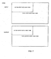
- FIG. 7 is an illustration of input and output dimension for HD project resampling for NTSC.
- FIG. 8 is an illustration of input and output dimension for HD project resampling for PAL.
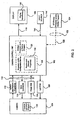
- FIG. 1 depicts a system 100 comprising a camera 104 for generating image data.
- Camera 104 is connected to camera control unit 102 via a coupling 116.
- the coupling 116 is provided to supply electrical power to camera 104 as well as to transmit data between camera 104 and camera control unit 102.
- Camera control unit 102 is provided with at least two different inputs, including, a High-Definition (HD) Input 108 and a Standard-Definition (SD) Input 110.
- HD High-Definition
- SD Standard-Definition
- SD generally refers to a line count of up to approximately 720 x 480 NTSC and PAL; while HD refers to systems that utilize a higher line count and may include, for example but not limited to, 1280 x 720 progressive or 1920 x 1080 or interlaced, which are only two of the commonly used HD resolutions.
- HD generally refers to a line count of up to approximately 720 x 480 NTSC and PAL; while HD refers to systems that utilize a higher line count and may include, for example but not limited to, 1280 x 720 progressive or 1920 x 1080 or interlaced, which are only two of the commonly used HD resolutions.
- a user will attach the camera to either the HD input 108 or the SD input 110.
- processor / configurable device 128 shown in camera control unit 102. Based on the connected camera, the camera control unit 102 will be configured to function with the connected camera 104 via either the HD input 108 or the SD input 110.
- a display 106 may be connected to camera control unit 102 via a coupling 118. Upon connection, the camera control unit 102 can detect the attached display 106 and determine the correct signal format for proper functioning of display 106. For example, display 106 may be designed to display only SD video signals. That being the case, camera control unit 102 will transmit an SD signal format to display 106 whether an SD or an HD camera is connected. Alternatively, it may be determined that the connected display 106 may be designed to display HD video signals. In this case, if the connected camera 104 is an HD camera, an HD signal is transmitted to display 106.
- an enhanced SD signal may be transmitted to the HD display 106.
- the following signal format types may be used SD input ⁇ SD output ; SD input ⁇ Enhanced SD output ; HD input ⁇ SD output ; and HD input ⁇ HD output .
- categorization of inputs and outputs as SD or HD is not intended to limit the categories to a single signal format, but rather, many differing signal formats may be categorized as SD and many differing signal formats may be categorized as HD.
- configuration information for either camera 104 and / or display 106 may be located on camera 104 and display 106 respectively.
- configuration information may be located in storage 126 that may comprise an internal storage device for camera control unit 102 with camera 104 and display 106 providing an identifier for camera control unit 102 to look up the correct configuration information.
- configuration information may be remotely located and may be transmitted to camera control unit 102 via a line 120 over a network connection 122 from a remote storage 124.
- the network connection 122 may include, for example, an Intranet, the Internet and / or the like.
- a camera identifier / program 130 stored on camera 104 may be transmitted as camera information / program(s) 132 to camera control unit 102.
- the camera identifier may comprise discrete data or may comprise a program.
- one or more programs may be stored on camera 104 and transmitted as or with the camera identification data.
- the processor and / or configurable device 128 receives the camera information / program(s) and executes the program(s) 142, which allows the processor and / or configurable device 128 to receive and process image data generated and transmitted by camera 104.
- one or more programs may be located on internal storage 126 or may be located on remote storage 124.
- camera identifier 130 may be transmitted to camera control unit 102.
- a program(s) may be transmitted to processor and / or configurable device 128 from camera 104, internal storage 126 or remote storage 124.
- camera control unit 102 may issue commands 134 to camera 104, for example, to adjust color balance, light, focal distance, resolution, zoom, focus, shading, and other optical characteristics.
- Camera 104 may then generate and transmit image data 136, which is received and processed by camera control unit 102.
- Image data received and processed by camera control unit 102 is then transmitted in the proper signal format to display 106.
- light path 138, 140 and light source 144 may comprise virtually any type of commonly used light source including, for example, a Light Emitting Diode while the light path may comprise, for instance, a coherent or non-coherent fiber optic bundle. While the light path 138, 140 is illustrated passing through camera control unit 102, it is contemplated that the light path may be separate and apart from camera control unit 102. Additionally, it is contemplated that light path 138 may be combined into coupling 116 or light source 144 may be provided in camera 104, or camera control unit 102.
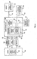
- FIG. 3 illustrates still another advantageous embodiment of the present invention.
- display identifier 146 stored on display 106 is transmitted as display identification 148 to camera control unit 102.
- camera control unit 102 will determine a signal format that will be compatible with display 106.
- Image data 150 will then be transmitted to display 106 in the properly configured signal format.
- camera control unit 102 can retrieve information and / or a program from, for example, internal storage 126, remote storage 124 or even from display 106 for configuration of the output signal for sending image data 150 in the proper format.
- Example 1 For NTSC the specifications in one advantageous embodiment are as follows:
- Total input data active and inactive.
- Total number of input lines 525.
- To find the total number of pixels per line: in 1 second there are 145.2727 x 10 6 pixels. Also, in 1 second there are 60/1.001 frames of (525 x total number of pixels per input line (145.2727 ⁇ 10 6 / ((60/1.001) x 525) 4680.
- Example 2 For PAL the specifications in one advantageous embodiment are as follows:
- Total input data active and inactive.
- Total number of input lines 625.
- To find the total number of pixels per line: in 1 second there are 127.6875 x 10 6 pixels. Also, in 1 second there are 50 frames of (625 x total number of pixels per input line (127.6875 x 10 6 / (50 x 625) 4086.
- NTSC and PAL SD NTSC and PAL
- RGB NTSC and PAL
- Y/C s-video
- Serial Digital Interface (SDI), standardized in ITU-R BT.656 and SMPTE 259M, is a digital video interface used for broadcast-grade video.
- a related standard, known as High Definition Serial Digital Interface (HD-SDI) is standardized in SMPTE 292M and provides a nominal data rate of 1.485 Gbit/s.
- Digital Visual Interface is a video interface standard designed to maximize the visual quality of digital display devices such as flat panel LCD computer displays and digital projectors and is partially compatible with the HDMI standard in digital mode (DVI-D).
- the DVI interface uses a digital protocol in which the desired illumination of pixels is transmitted as binary data. When the display is driven at its native resolution, it will read each number and apply that brightness to the appropriate pixel. In this way, each pixel in the output buffer of the source device corresponds directly to one pixel in the display device.
- HDMI High-Definition Multimedia Interface
- HDMI is an all-digital audio/visual interface capable of transmitting uncompressed streams.
- HDMI is compatible with High-bandwidth Digital Content Protection (HDCP) Digital Rights Management technology.
- HDMI provides an interface between any compatible digital audio/video source and a compatible digital audio and / or video monitor, such as a digital television (DTV).
- DTV digital television
- a storage device for storing the program(s) for configuration of the processor and / or configurable device 128 may reside on camera 104, internal storage 126, a removable storage 154 (e.g. a removable drive or storage medium) or a remote storage 124 (e.g. via a network connection).
- camera control unit 102 can compare program(s) versions from the various storage mediums to determine if the camera identification /program(s) received from camera 104 is the latest version and if not, the camera information can be updated. This can happen automatically, or the system could, for example, prompt the user to decide whether or not to update the camera information.
- certain programs and / or features may become available.
- FIGS. 5 and 6 illustrate the camera control unit 102 per one embodiment of the present invention.
- Camera control unit 102 includes a case 160 having a front panel 162.
- Front panel 162 is provided with multiple inputs including, an HD receptacle 164 and an SD receptacle 166.
- a power switch 168 may also be positioned on front panel 162.
- Also positioned on front panel 162 is slideable door 170 and tracks 172.
- a camera 104 is provided with a plug (not shown) that, based upon the camera configuration (e.g. either HD or SD), is keyed to fit in either HD receptacle 164 or SD receptacle 166.
- the door 170 may simply be slid to cover the receptacle that is not currently in use.
- the door is provided with a protrusion(s) (not shown) that engage with a channel 174 provided in tracks 172 so as to capture door 170 but still allow for lateral sliding action.
- HD receptacle 164 and SD receptacle 166 are not illustrated including an optical connection or coupling, it is contemplated that they may be provided with such.
Abstract
Description
- The invention relates to a multi-function camera control unit, and more particularly, to a camera control unit that is capable of receiving inputs from multiple different types of cameras having diverse signal formats and may generate diverse output signals compatible with differing displays.
- A Camera Control Unit ("CCU") is generally used in conjunction with a camera to capture and process images. The camera may include charge couple devices ("CCD"), CMOS devices or any other type of image capture device. They are typically used in conjunction with an endoscope to generate image data of an area to be viewed during a procedure. The image data is transmitted to the CCU. The CCU then processes the image data into displayable image data to be sent to a display. The CCU may also send commands to the camera in order to operate and adjust camera settings.
- Known CCUs typically control a single type of camera by receiving and processing image data generated by the camera. The CCU controls the camera by adjusting color balance, light, focal distance, resolution, zoom, focus, shading, and other typical optical characteristics.
- Traditionally, CCUs have been compatible with a limited number of devices because the control unit hardware, through which commands were sent and image signals were received, was difficult to configure to communicate with the many different types of devices in the market. For example, different devices may have varying electronic requirements /connections in order to function properly. Devices may be either analog or digital. In addition, some types of cameras are designated to pick up certain colors such as red or green while others pick up blue. In addition, as changes and improvements are made to devices, a control unit's hardware, which was configured to be compatible with older devices, may become incompatible and may need to be upgraded as well.
- Because a CCU was compatible with limited quantities of devices, older CCUs were typically discarded in favor of CCUs that were made concurrently with particular devices. In order to address compatibility problems, configurable CCUs were introduced to function with a number of differing camera types.
- For example,
U.S. Patent No. 5,627,583 ("Nakamura et al. ") relates to an electroendoscope system that is compatible with a plurality of different endoscope types. However, Nakamura et al. fails to teach, disclose or suggest a system that is compatible with fundamentally differing signal types, such as for instance, a standard definition and a high-definition signal format. In addition, Nakamura et al. fails to teach or suggest a system that is compatible or usable with numerous differing display types, such as for instance, standard definition and high-definition displays. Therefore, while Nakamura et al. does provide for some versatility with regard to the attached camera, e.g. can configure itself to control the attached camera and receive the generated image signal, the CCU taught in Nakamura et al. is still limited to being able to receive a single type of image signal input (e.g. an analog input) and a single image signal format output (See, Col. 3, In. 60 - Col. 4, In. 4; Col. 4, Ins. 58-67). - What is desired, therefore, is to provide a system and method that is capable of maintaining compatibility different devices that may have fundamentally different signal formats.
- It is also desired to provide a system and method that can automatically detect the type of device attached and can then automatically configure itself to be compatible with and control the attached device.
- It is further desired to provide a system and method that is compatible with many different types of displays.
- It is still further desired to provide a system and method that can automatically detect the type of connected display and can then automatically configure itself to be compatible with and control the attached display.
- It is yet further desired to provide a system and method that can receive information from a connected device and automatically detect whether the received information is most up-to-date information for the attached device and if not, provide upgraded information to the attached device.
- It is still further desired to provide a system and method that can accept either a standard or a high definition input signal from an input device and provide either a standard or a high definition output signal for an attached output device.
- These and other objects are achieved in one advantageous embodiment in which a video imaging system is provided including a CCU the can automatically sense and identify a connected device, such as a camera, the CCU configuring and/or programming itself based on the identified device. A camera is provided to receive reflected light from an area to be viewed and for generation of image data representative of the reflected light. There are many different types of cameras and a number of different signal formats for the image data including, for example, Standard Definition (SD) and High Definition (HD) signals. In order to configure itself, the CCU retrieves and / or receives a program or multiple programs stored on a storage device. The retrieved program(s) execute on the camera control unit for enabling the camera control unit to process the image data. The digital input signal from an attached camera can vary widely, for example they may include but not are limited to ranges from 200 x 200 pixel resolution to 1920 x 1080 pixel resolution.
- It is contemplated that the storage device may be any type of storage medium accessible by the control unit. For instance, it may be an internal, external, or removable drive and may also include a remote location, such as an Internet location. The storage device may also be located within the camera and/or the CCU. It is further contemplated that multiple storage devices and/or locations may be used to provide the latest version of software and/or programs for the configurable control unit.
- In addition, the CCU also senses and identifies a connected display and configures an output signal to be compatible with the identified display. The output signal may variously be compatible with, for example, NTSC or PAL formats and may be provided as an SD or an HD signal. In addition to providing a compatible video signal output to an attached display, the CCU configures output control signals to properly control the attached display.
- The CCU may be provided as a field programmable gate array (e.g. a configurable hardware device) or may be provided as a microprocessor or a Digital Signal Processor (DSP) (e.g. a soft configurable device). In any event, the CCU detects and identifies the connected device, e.g. a particular camera and/or a particular display, storage or other device, and configures itself to be compatible with the connected devices both for function and control. To function properly with a camera, the CCU will configure itself so as to be able to receive image data from and to be able to send command signals to the camera to control, for example, the camera's optical functional characteristics including: focal distance, resolution, light balance or color and the like.
- In one advantageous embodiment, the CCU is provided with a microprocessor that receives a processor program for programming the microprocessor and a device program for programming and / or configuring the configurable device to process the received image data.
- The term "data" as used herein means any indicia, signals, marks, symbols, domains, symbol sets, representations, and any other physical form or forms representing information, whether permanent or temporary, whether visible, audible, acoustic, electric, magnetic, electromagnetic or otherwise manifested. The term "data" as used to represent predetermined information in one physical form shall be deemed to encompass any and all representations of the same predetermined information in a different physical form or forms.
- The term "network" as used herein includes both networks and internetworks of all kinds, including the Internet, and is not limited to any particular network, inter-network, or intra-network.
- The terms "coupled", "coupled to", and "coupled with" as used herein each mean a relationship between or among two or more devices, apparatus, files, programs, media, components, networks, systems, subsystems, and/or means, constituting any one or more of (a) a connection, whether direct or through one or more other devices, apparatui, files, programs, media, components, networks, systems, subsystems, or means, (b) a communications relationship, whether direct or through one or more other devices, apparatui, files, programs, media, components, networks, systems, subsystems, or means, and/or (c) a functional relationship in which the operation of any one or more devices, apparatui, files, programs, media, components, networks, systems, subsystems, or means depends, in whole or in part, on the operation of any one or more others thereof.
- In one advantageous embodiment, a video endoscopic system is provided comprising, a camera for generating image data and a display for displaying the image data. The system further comprises a camera control unit coupling the camera to the display. The camera control unit has a first input for transmitting and receiving a first signal format and a second input for transmitting and receiving a second signal format that is different from the first signal format. The camera control unit also has an output for transmitting the image data to the display.
- In another advantageous embodiment, a method for transmitting image data from multiple cameras having differing signal formats to a camera control unit and a display is provided comprising the step of providing, a first receptacle and a second receptacle in the camera control unit, the first receptacle having a first configuration and the second receptacle having a second configuration that is different from the first configuration. The method further comprises the steps of providing a camera having one of either a first plug configuration or a second plug configuration that couples to the first and second receptacle configurations respectively, coupling the camera to one of the first or second receptacles and receiving a camera identifier and a program. The method still further comprises the steps of configuring the camera control unit based on the camera identifier and received program, coupling the camera control unit to the display and receiving a display identifier. Finally, the method comprises the steps of configuring an output signal to be compatible with the connected display, transmitting image data to the display and displaying the image data on the display.
- Other objects of the invention and its particular features and advantages will become more apparent from consideration of the following drawings and accompanying detailed description.
-
FIG. 1 is a block diagram of one advantageous embodiment of the present invention. -
FIG. 2 is a block diagram of the advantageous embodiment according toFIG. 1 . -
FIG. 3 is a block diagram of the advantageous embodiment according toFIG. 1 . -
FIG. 4 is a block diagram of the advantageous embodiment according toFIG. 1 . -
FIG. 5 is an illustration of the Camera Control Unit according to the advantageous embodiment ofFIG. 1 . -
FIG. 6 is an illustration of the Camera Control Unit according to the advantageous embodiment ofFIG. 1 . -
FIG. 7 is an illustration of input and output dimension for HD project resampling for NTSC. -
FIG. 8 is an illustration of input and output dimension for HD project resampling for PAL. - Referring now to the drawings, wherein like reference numerals designate corresponding structure throughout the views.
-
FIG. 1 depicts a system 100 comprising acamera 104 for generating image data.Camera 104 is connected tocamera control unit 102 via acoupling 116. Thecoupling 116 is provided to supply electrical power tocamera 104 as well as to transmit data betweencamera 104 andcamera control unit 102.Camera control unit 102 is provided with at least two different inputs, including, a High-Definition (HD)Input 108 and a Standard-Definition (SD)Input 110. As used in this application, SD generally refers to a line count of up to approximately 720 x 480 NTSC and PAL; while HD refers to systems that utilize a higher line count and may include, for example but not limited to, 1280 x 720 progressive or 1920 x 1080 or interlaced, which are only two of the commonly used HD resolutions. Depending on the camera type (SD or HD) a user will attach the camera to either theHD input 108 or theSD input 110. - Also shown in
FIG. 1 is processor /configurable device 128 shown incamera control unit 102. Based on the connected camera, thecamera control unit 102 will be configured to function with theconnected camera 104 via either theHD input 108 or theSD input 110. - Two different output types are illustrated in
FIG. 1 including,HD output 112 andSD output 114. It is contemplated that adisplay 106 may be connected tocamera control unit 102 via acoupling 118. Upon connection, thecamera control unit 102 can detect the attacheddisplay 106 and determine the correct signal format for proper functioning ofdisplay 106. For example,display 106 may be designed to display only SD video signals. That being the case,camera control unit 102 will transmit an SD signal format to display 106 whether an SD or an HD camera is connected. Alternatively, it may be determined that theconnected display 106 may be designed to display HD video signals. In this case, if theconnected camera 104 is an HD camera, an HD signal is transmitted to display 106. If however, anSD camera 104 is connected tocamera control unit 102, an enhanced SD signal may be transmitted to theHD display 106. In this manner the following signal format types may be used SDinput → SDoutput; SDinput → Enhanced SDoutput; HDinput → SDoutput; and HDinput → HDoutput. It should be noted that categorization of inputs and outputs as SD or HD is not intended to limit the categories to a single signal format, but rather, many differing signal formats may be categorized as SD and many differing signal formats may be categorized as HD. - It is contemplated that configuration information for either
camera 104 and / ordisplay 106 may be located oncamera 104 and display 106 respectively. Alternatively, configuration information may be located instorage 126 that may comprise an internal storage device forcamera control unit 102 withcamera 104 and display 106 providing an identifier forcamera control unit 102 to look up the correct configuration information. Still further, configuration information may be remotely located and may be transmitted tocamera control unit 102 via aline 120 over anetwork connection 122 from aremote storage 124. Thenetwork connection 122 may include, for example, an Intranet, the Internet and / or the like. - Referring now to
FIG. 2 , an advantageous embodiment of the interaction betweencamera 104 andcamera control unit 102 is illustrated. For example, upon connection ofcamera 104 tocamera control unit 102, a camera identifier /program 130 stored oncamera 104 may be transmitted as camera information / program(s) 132 tocamera control unit 102. It is contemplated that the camera identifier may comprise discrete data or may comprise a program. In addition, it is contemplated that one or more programs may be stored oncamera 104 and transmitted as or with the camera identification data. The processor and / orconfigurable device 128 receives the camera information / program(s) and executes the program(s) 142, which allows the processor and / orconfigurable device 128 to receive and process image data generated and transmitted bycamera 104. - It is further contemplated that one or more programs may be located on
internal storage 126 or may be located onremote storage 124. For example, upon connection ofcamera 104 tocamera control unit 102,camera identifier 130 may be transmitted tocamera control unit 102. Once identified, a program(s) may be transmitted to processor and / orconfigurable device 128 fromcamera 104,internal storage 126 orremote storage 124. - Once processor and / or
configurable device 128 is properly configured to function withcamera 104,camera control unit 102 may issuecommands 134 tocamera 104, for example, to adjust color balance, light, focal distance, resolution, zoom, focus, shading, and other optical characteristics.Camera 104 may then generate and transmitimage data 136, which is received and processed bycamera control unit 102. Image data received and processed bycamera control unit 102 is then transmitted in the proper signal format to display 106. - Also illustrated in
FIG. 2 islight path light source 144. It is contemplated thatlight source 144 may comprise virtually any type of commonly used light source including, for example, a Light Emitting Diode while the light path may comprise, for instance, a coherent or non-coherent fiber optic bundle. While thelight path camera control unit 102, it is contemplated that the light path may be separate and apart fromcamera control unit 102. Additionally, it is contemplated thatlight path 138 may be combined intocoupling 116 orlight source 144 may be provided incamera 104, orcamera control unit 102. -
FIG. 3 illustrates still another advantageous embodiment of the present invention. In this embodiment,display identifier 146 stored ondisplay 106 is transmitted asdisplay identification 148 tocamera control unit 102. Once received,camera control unit 102 will determine a signal format that will be compatible withdisplay 106.Image data 150 will then be transmitted to display 106 in the properly configured signal format. - There are commonly used types of signal formats that are typically used, however, it is contemplated that additional formats may be provided for and especially new signal formats that may become available. The two commonly used SD format types are NTSC and PAL. It should be noted that these are just two video signal formats and that there are many differing types and modifications to the above-listed types including, for example, a modified version Phase-Alternating Line (PAL-M). In any event, upon receipt of
display information 148,camera control unit 102 can retrieve information and / or a program from, for example,internal storage 126,remote storage 124 or even fromdisplay 106 for configuration of the output signal for sendingimage data 150 in the proper format. - A number of examples will be provided of the input and output dimensions for HD resampling of NTSC and PAL formats. The following examples are presented to further illustrate and explain the present invention and should not be taken as limiting in any regard.
- Example 1. For NTSC the specifications in one advantageous embodiment are as follows:
- Active data: 484 x 756
- Pixel dimensions: 4.75 H x 5.55 V
- FPS: 60/1.001 = 59.9401
- Dimensions of total input data (active and inactive). Total number of input lines: 525. To find the total number of pixels per line: in 1 second there are 145.2727 x 106 pixels. Also, in 1 second there are 60/1.001 frames of (525 x total number of pixels per input line (145.2727 ×10⁶ / ((60/1.001) x 525) = 4680.
- Dimensions of total output data (active and inactive). Total number of output lines: 1125. We can use the fact that the input and output frame correspond to the same frame time. The total number of pixels per output line is then: (525 x 4680) / 1125 = 2184.
- Dimensions of active input data. Out of a total of 525 lines, we assume that 483 contain valid data (active lines). The number of input active lines is: 483. The number of pixels per active line is: 756 oversampled by 2 = 1512. The active lines need to be resampled (vertically) by a factor of 1125 /525. The number of output lines is: 483 x 1125 / 525 = 1035. It should be noted that, in this case, 1125 / 525 gives an integer value so we can work with; 1125 / 525 or 1035 / 483. Otherwise, the active line ratio should be used. To determine the number of output pixels, we consider the ratio of vertical resampling as well as the fact that the pixels need to be converted to square dimension. The number of output square pixels = (1512 / 2 x (4.75H /5.55V)) x (1035 / 483) = 1386.5 ~1386.
FIG. 7 illustrates these numbers. - Example 2. For PAL the specifications in one advantageous embodiment are as follows:
- Active data: 576 x 742
- Pixel dimensions: 4.85 H x 4.65 V
- FPS: 50 (exactly)
- Dimensions of total input data (active and inactive). Total number of input lines: 625. To find the total number of pixels per line: in 1 second there are 127.6875 x 106 pixels. Also, in 1 second there are 50 frames of (625 x total number of pixels per input line (127.6875 x 10⁶ / (50 x 625) = 4086.
- Dimensions of total output data (active and inactive). Total number of output lines: 1125. We can use the fact that the input and output frame correspond to the same frame time. The total number of pixels per output line is then: (625 x 4086) / 1125 = 2270.
- Dimensions of active input data. Out of a total of 625 lines, we assume that 573 contain valid data (active lines). The number of input active lines is: 575. The number of pixels per active line is: 742 oversampled by 2 = 1484. The active lines need to be resampled (vertically) by a factor of 1125 / 625. The number of output lines is: 575 x 1125 / 625 = 1035. To determine the number of output pixels, we consider the ratio of vertical resampling as well as the fact that the pixels need to be converted to square dimension. The number of output square pixels = (1484/2 x (4.85H / 4.65V)) x (1035 / 575) = 1393.
FIG. 8 illustrates these numbers. - In addition to the standard NTSC and PAL SD (NTSC and PAL) composite, RGB, and s-video (Y/C) outputs, numerous other outputs may be used. The following examples are presented to further illustrate and explain the present invention and should not be taken as limiting in any regard.
- Serial Digital Interface (SDI), standardized in ITU-R BT.656 and SMPTE 259M, is a digital video interface used for broadcast-grade video. A related standard, known as High Definition Serial Digital Interface (HD-SDI), is standardized in SMPTE 292M and provides a nominal data rate of 1.485 Gbit/s.
- Digital Visual Interface (DVI) is a video interface standard designed to maximize the visual quality of digital display devices such as flat panel LCD computer displays and digital projectors and is partially compatible with the HDMI standard in digital mode (DVI-D). The DVI interface uses a digital protocol in which the desired illumination of pixels is transmitted as binary data. When the display is driven at its native resolution, it will read each number and apply that brightness to the appropriate pixel. In this way, each pixel in the output buffer of the source device corresponds directly to one pixel in the display device.
- High-Definition Multimedia Interface (HDMI) is an all-digital audio/visual interface capable of transmitting uncompressed streams. HDMI is compatible with High-bandwidth Digital Content Protection (HDCP) Digital Rights Management technology. HDMI provides an interface between any compatible digital audio/video source and a compatible digital audio and / or video monitor, such as a digital television (DTV).
- Referring now to
FIG. 4 it is contemplated that a storage device for storing the program(s) for configuration of the processor and / orconfigurable device 128 may reside oncamera 104,internal storage 126, a removable storage 154 (e.g. a removable drive or storage medium) or a remote storage 124 (e.g. via a network connection). In this manner, when thecamera control unit 102 receives the camera identification / program(s) 132 fromcamera 104,camera control unit 102 can compare program(s) versions from the various storage mediums to determine if the camera identification /program(s) received fromcamera 104 is the latest version and if not, the camera information can be updated. This can happen automatically, or the system could, for example, prompt the user to decide whether or not to update the camera information. In addition, it is contemplated that based upon user access, certain programs and / or features may become available. -
FIGS. 5 and 6 illustrate thecamera control unit 102 per one embodiment of the present invention.Camera control unit 102 includes acase 160 having afront panel 162.Front panel 162 is provided with multiple inputs including, anHD receptacle 164 and anSD receptacle 166. In addition, apower switch 168 may also be positioned onfront panel 162. Also positioned onfront panel 162 isslideable door 170 and tracks 172. It is contemplated that acamera 104 is provided with a plug (not shown) that, based upon the camera configuration (e.g. either HD or SD), is keyed to fit in eitherHD receptacle 164 orSD receptacle 166. Thedoor 170 may simply be slid to cover the receptacle that is not currently in use. The door is provided with a protrusion(s) (not shown) that engage with achannel 174 provided intracks 172 so as to capturedoor 170 but still allow for lateral sliding action. - It should be noted that, while
HD receptacle 164 andSD receptacle 166 are not illustrated including an optical connection or coupling, it is contemplated that they may be provided with such. - Although the invention has been described with reference to a particular arrangement of parts, features and the like, these are not intended to exhaust all possible arrangements or features, and indeed many other modifications and variations will be ascertainable to those of skill in the art.
Claims (30)
- A video endoscopic system comprising:a camera for generating image data;a display for displaying the image data;a camera control unit coupling said camera to said display, said camera control unit having:a first input for receiving image data having first signal format;a second input for receiving image data having second signal format that is different from said first signal format; andan output for transmitting the image data to said display.
- The video endoscopic system of claim 1, wherein said first input comprises a first receptacle and said second input comprises a second receptacle.
- The video endoscopic system of claim 2, wherein said first receptacle is configured to receive a first plug and said second receptacle is configured to receive a second plug, where said first and second plugs comprise different configurations.
- The video endoscopic system of claim 2 or 3, further comprising a door that selectively covers one of either said first or said second receptacles.
- The video endoscopic system of claim 4, wherein said door is slideable such that when the door covers said first receptacle, said second receptacle is exposed; and when said door covers said second receptacle, said first receptacle is exposed.
- The video endoscopic system of claim 5, further comprising a track engaging with said slideable door, said slideable door comprising a protrusion that engages with a recess in said track.
- The video endoscopic system of claim 6, wherein said track comprises at least two tracks, each track having a recess, and said slideable door comprises at least two protrusions that engage with said recesses.
- The video endoscopic system of anyone of claims 1 through 7, wherein said first input comprises High-Definition (HD) input image data, and said second input comprises a Standard-Definition (SD) input image data.
- The video endoscopic system according to anyone of claims 1 through 8, wherein upon connection with said display, said camera control unit determines a compatible output signal format for said display.
- The video endoscopic system of claim 9 wherein the output signal format is selected from the group consisting of: NTSC, PAL, Serial Digital Interface (SDI), High Definition Serial Digital Interface (HD-SDI), Digital Visual Interface (DVI), High-Definition Multimedia Interface (HDMI) and combinations thereof.
- The video endoscopic system of anyone of claims 1 through 10, wherein upon connection of said camera to said camera control unit, a camera identifier and a program are transmitted to said camera control unit such that said camera control unit configures itself to be compatible with said camera.
- The video endoscopic system of claim 11, wherein said camera control unit further comprises a microprocessor for receiving and executing the program and a configurable portion for receiving the image data.
- The video endoscopic system of claim 12, wherein said microprocessor compares the received program with a second version of the program to determine if the received program is a latest version and if not, said camera is updated with the latest version of the program.
- The video endoscopic system of claim 13, wherein the second version of the program is accessible by said microprocessor via: an internal storage, a removable storage and/or a network connection to a remote storage.
- The video endoscopic system of anyone of claims 12 through 14, wherein said camera transmits a processor program for programming said microprocessor and a device program for programming the configurable portion.
- The video endoscopic system of anyone of claims 12 through 15, wherein said configurable portion is selected from the group consisting of: a field programmable gate array, a microprocessor, a digital signal processor and combinations thereof.
- The video endoscopic system of anyone of claims 1 through 16, wherein said camera is coupled to an endoscope via a coupling mechanism.
- The video endoscopic system of claim 17, further comprising an illumination channel coupled to the endoscope, said illumination channel directing illuminating light to the endoscope from a light source.
- A method for transmitting image data from multiple cameras having differing signal formats to a camera control unit and a display via a camera control comprising the steps of:providing a first receptacle and a second receptacle in the camera control unit, the first receptacle having a first configuration and the second receptacle having a second configuration that is different from the first configuration;providing a camera having one of either the first plug configuration or the second plug configuration that couples to the first or second receptacle configurations respectively;coupling the camera to one of the first or second receptacles;receiving a camera identifier and a program;configuring the camera control unit based on the camera identifier and received program;coupling the camera control unit to the display;receiving a display identifier;configuring an output signal to be compatible with the connected display;transmitting the image data to the display; anddisplaying the image data on the display.
- The method of claim 19, further comprising the step of selectively covering one of the first or second receptacles with a slideable door.
- The method of claim 19 or 20, wherein said first input is a High-Definition (HD) image data input, and said second input is a Standard-Definition (SD) image data input.
- The method of claim 21, further comprising the steps of scaling the image data received from the camera to a scaled size formal compatible with the identified display.
- The method of claim 22, wherein when the identified display is compatible with NTSC the HD image data is scaled according to a first process, and when the display is compatible with PAL the SD image data is scaled according to a second process that is different from the first process.
- The method of anyone of claims 19 through 23, wherein the program is received from and stored on the camera.
- The method of claim 24, wherein the camera control unit compares the program received from the camera with another version of the program to determine if the received program is a latest version and if not, the camera is updated with the latest version of the program.
- A video endoscopic system, comprising:a camera for generating image data;a plurality of displays for displaying the image data, each of said plurality of displays having different input signal requirements;a camera control unit coupling said camera to one of said plurality of displays;a display identifier identifying a particular display coupled to said camera control unit;wherein upon connection of said camera control unit with one of said plurality of differing displays, said camera control unit determines a compatible output signal format for said connected display and configures itself accordingly.
- The video endoscopic system of claim 26, wherein upon connection of said display to said camera control unit, a program is received by said camera control unit.
- The video endoscopic system of claim 26 or 27, wherein the output signal format is selected from the group consisting of: NTSC, PAL, Serial Digital Interface (SDI), High Definition Serial Digital Interface (HD-SDI), Digital Visual Interface (DVI), High-Definition Multimedia Interface (HDMI) and combinations thereof.
- The video endoscopic system of anyone of claims 26 through 28 wherein upon connection of said camera to said camera control unit, said camera control unit receives a camera identifier identifying the connected camera and said camera control unit configures itself to be compatible with said connected camera.
- The video endoscopic system of anyone of claims 26 through 29, wherein said camera control unit further comprises a first input for receiving image data having a first signal format and a second input for receiving image data having a second signal format that is different from said image data having the first signal format.
Priority Applications (1)
| Application Number | Priority Date | Filing Date | Title |
|---|---|---|---|
| EP13175797.3A EP2649927A3 (en) | 2007-04-03 | 2008-03-29 | Universal camera control unit |
Applications Claiming Priority (1)
| Application Number | Priority Date | Filing Date | Title |
|---|---|---|---|
| US11/695,960 US8810637B2 (en) | 2007-04-03 | 2007-04-03 | Universal camera control unit |
Related Child Applications (2)
| Application Number | Title | Priority Date | Filing Date |
|---|---|---|---|
| EP13175797.3A Division EP2649927A3 (en) | 2007-04-03 | 2008-03-29 | Universal camera control unit |
| EP13175797.3 Division-Into | 2013-07-09 |
Publications (3)
| Publication Number | Publication Date |
|---|---|
| EP1977682A2 true EP1977682A2 (en) | 2008-10-08 |
| EP1977682A3 EP1977682A3 (en) | 2008-12-17 |
| EP1977682B1 EP1977682B1 (en) | 2013-12-25 |
Family
ID=39638858
Family Applications (2)
| Application Number | Title | Priority Date | Filing Date |
|---|---|---|---|
| EP08006213.6A Active EP1977682B1 (en) | 2007-04-03 | 2008-03-29 | Universal camera control unit |
| EP13175797.3A Withdrawn EP2649927A3 (en) | 2007-04-03 | 2008-03-29 | Universal camera control unit |
Family Applications After (1)
| Application Number | Title | Priority Date | Filing Date |
|---|---|---|---|
| EP13175797.3A Withdrawn EP2649927A3 (en) | 2007-04-03 | 2008-03-29 | Universal camera control unit |
Country Status (4)
| Country | Link |
|---|---|
| US (1) | US8810637B2 (en) |
| EP (2) | EP1977682B1 (en) |
| JP (1) | JP4890489B2 (en) |
| CA (1) | CA2618510C (en) |
Cited By (30)
| Publication number | Priority date | Publication date | Assignee | Title |
|---|---|---|---|---|
| EP2749201A1 (en) * | 2012-12-31 | 2014-07-02 | Karl Storz Imaging Inc. | Modular medical imaging system |
| US8926502B2 (en) | 2011-03-07 | 2015-01-06 | Endochoice, Inc. | Multi camera endoscope having a side service channel |
| US9101287B2 (en) | 2011-03-07 | 2015-08-11 | Endochoice Innovation Center Ltd. | Multi camera endoscope assembly having multiple working channels |
| US9101268B2 (en) | 2009-06-18 | 2015-08-11 | Endochoice Innovation Center Ltd. | Multi-camera endoscope |
| US9101266B2 (en) | 2011-02-07 | 2015-08-11 | Endochoice Innovation Center Ltd. | Multi-element cover for a multi-camera endoscope |
| EP2749199A3 (en) * | 2012-12-31 | 2016-03-16 | Karl Storz Imaging Inc. | Video imaging system with multiple camera white balance capability |
| US9314147B2 (en) | 2011-12-13 | 2016-04-19 | Endochoice Innovation Center Ltd. | Rotatable connector for an endoscope |
| US9320419B2 (en) | 2010-12-09 | 2016-04-26 | Endochoice Innovation Center Ltd. | Fluid channeling component of a multi-camera endoscope |
| US9402533B2 (en) | 2011-03-07 | 2016-08-02 | Endochoice Innovation Center Ltd. | Endoscope circuit board assembly |
| US9492063B2 (en) | 2009-06-18 | 2016-11-15 | Endochoice Innovation Center Ltd. | Multi-viewing element endoscope |
| US9554692B2 (en) | 2009-06-18 | 2017-01-31 | EndoChoice Innovation Ctr. Ltd. | Multi-camera endoscope |
| US9560953B2 (en) | 2010-09-20 | 2017-02-07 | Endochoice, Inc. | Operational interface in a multi-viewing element endoscope |
| US9560954B2 (en) | 2012-07-24 | 2017-02-07 | Endochoice, Inc. | Connector for use with endoscope |
| US9642513B2 (en) | 2009-06-18 | 2017-05-09 | Endochoice Inc. | Compact multi-viewing element endoscope system |
| US9655502B2 (en) | 2011-12-13 | 2017-05-23 | EndoChoice Innovation Center, Ltd. | Removable tip endoscope |
| US9706903B2 (en) | 2009-06-18 | 2017-07-18 | Endochoice, Inc. | Multiple viewing elements endoscope system with modular imaging units |
| US9713417B2 (en) | 2009-06-18 | 2017-07-25 | Endochoice, Inc. | Image capture assembly for use in a multi-viewing elements endoscope |
| US9814374B2 (en) | 2010-12-09 | 2017-11-14 | Endochoice Innovation Center Ltd. | Flexible electronic circuit board for a multi-camera endoscope |
| US9872609B2 (en) | 2009-06-18 | 2018-01-23 | Endochoice Innovation Center Ltd. | Multi-camera endoscope |
| US9901244B2 (en) | 2009-06-18 | 2018-02-27 | Endochoice, Inc. | Circuit board assembly of a multiple viewing elements endoscope |
| US9986899B2 (en) | 2013-03-28 | 2018-06-05 | Endochoice, Inc. | Manifold for a multiple viewing elements endoscope |
| US9993142B2 (en) | 2013-03-28 | 2018-06-12 | Endochoice, Inc. | Fluid distribution device for a multiple viewing elements endoscope |
| US10080486B2 (en) | 2010-09-20 | 2018-09-25 | Endochoice Innovation Center Ltd. | Multi-camera endoscope having fluid channels |
| US10165929B2 (en) | 2009-06-18 | 2019-01-01 | Endochoice, Inc. | Compact multi-viewing element endoscope system |
| US10203493B2 (en) | 2010-10-28 | 2019-02-12 | Endochoice Innovation Center Ltd. | Optical systems for multi-sensor endoscopes |
| US10499794B2 (en) | 2013-05-09 | 2019-12-10 | Endochoice, Inc. | Operational interface in a multi-viewing element endoscope |
| US11278190B2 (en) | 2009-06-18 | 2022-03-22 | Endochoice, Inc. | Multi-viewing element endoscope |
| US11547275B2 (en) | 2009-06-18 | 2023-01-10 | Endochoice, Inc. | Compact multi-viewing element endoscope system |
| US11864734B2 (en) | 2009-06-18 | 2024-01-09 | Endochoice, Inc. | Multi-camera endoscope |
| US11889986B2 (en) | 2010-12-09 | 2024-02-06 | Endochoice, Inc. | Flexible electronic circuit board for a multi-camera endoscope |
Families Citing this family (9)
| Publication number | Priority date | Publication date | Assignee | Title |
|---|---|---|---|---|
| US8633975B2 (en) | 2008-01-16 | 2014-01-21 | Karl Storz Imaging, Inc. | Network based endoscopic surgical system |
| US9603512B2 (en) | 2008-04-25 | 2017-03-28 | Karl Storz Imaging, Inc. | Wirelessly powered medical devices and instruments |
| US9526407B2 (en) * | 2008-04-25 | 2016-12-27 | Karl Storz Imaging, Inc. | Wirelessly powered medical devices and instruments |
| US20140142383A1 (en) * | 2012-11-22 | 2014-05-22 | Gyrus Acmi, Inc. (D.B.A. Olympus Surgical Technologies America) | Endoscope Camera Head Memory |
| US20140327751A1 (en) * | 2012-12-31 | 2014-11-06 | Timothy King | High definition (hd) inter-module link interface |
| JP6178099B2 (en) * | 2013-04-05 | 2017-08-09 | ソニー株式会社 | Intermediate unit and camera system |
| US10188411B2 (en) | 2013-04-16 | 2019-01-29 | Calcula Technologies, Inc. | Everting balloon for medical devices |
| US9232956B2 (en) | 2013-04-16 | 2016-01-12 | Calcula Technologies, Inc. | Device for removing kidney stones |
| US10219864B2 (en) | 2013-04-16 | 2019-03-05 | Calcula Technologies, Inc. | Basket and everting balloon with simplified design and control |
Citations (4)
| Publication number | Priority date | Publication date | Assignee | Title |
|---|---|---|---|---|
| US5627583A (en) | 1992-02-07 | 1997-05-06 | Olympus Optical Co., Ltd. | Electroendoscope apparatus |
| US5877819A (en) | 1993-03-31 | 1999-03-02 | Branson; Philip J. | Managing information in an endoscopy system |
| US20060050144A1 (en) | 2002-09-13 | 2006-03-09 | Kennedy Bruce L | Video recording and image capture device |
| GB2425424A (en) | 2005-04-22 | 2006-10-25 | Single Use Surgical Ltd | Disposable flexible endoscope |
Family Cites Families (41)
| Publication number | Priority date | Publication date | Assignee | Title |
|---|---|---|---|---|
| JPS61175868A (en) | 1985-01-31 | 1986-08-07 | Mitsubishi Electric Corp | Fingerprint discriminating device |
| JPS62140564A (en) * | 1985-12-13 | 1987-06-24 | Olympus Optical Co Ltd | Automatic dimmer for video camera |
| JPS62213073A (en) | 1986-03-14 | 1987-09-18 | 東芝ライテック株式会社 | Wiring appliance |
| JPH03156691A (en) | 1989-11-15 | 1991-07-04 | Fujitsu Ltd | Finger guide for reading fingerprint |
| US5347991A (en) * | 1992-10-20 | 1994-09-20 | Nakao Naomi L | Endoscope suction trap and associated method |
| US5589874A (en) * | 1993-06-09 | 1996-12-31 | Origin Medsystems, Inc. | Video imaging system with external area processing optimized for small-diameter endoscopes |
| JPH10269344A (en) | 1997-03-27 | 1998-10-09 | Sony Corp | Fingerprint reader |
| US6982742B2 (en) * | 1997-10-06 | 2006-01-03 | Adair Edwin L | Hand-held computers incorporating reduced area imaging devices |
| ES2137879B1 (en) * | 1997-12-02 | 2000-08-16 | Francisco Soria Melguizo S A | ANALYZING SYSTEM OF IMAGES PRODUCED BY BACTERIAL REACTIONS. |
| CA2327580C (en) | 1998-04-07 | 2009-01-27 | Gerald R. Black | Identification confirmation system |
| JP3950589B2 (en) * | 1998-08-28 | 2007-08-01 | キヤノン株式会社 | Information processing apparatus, program update method, and storage medium |
| US6768774B1 (en) * | 1998-11-09 | 2004-07-27 | Broadcom Corporation | Video and graphics system with video scaling |
| JP3915298B2 (en) | 1999-01-26 | 2007-05-16 | カシオ計算機株式会社 | Electronics |
| JP4042080B2 (en) | 1999-02-25 | 2008-02-06 | ソニー株式会社 | Editing device |
| JP3561485B2 (en) * | 2000-08-18 | 2004-09-02 | 株式会社メディアグルー | Coded signal separation / synthesis device, difference coded signal generation device, coded signal separation / synthesis method, difference coded signal generation method, medium recording coded signal separation / synthesis program, and difference coded signal generation program recorded Medium |
| US6471649B1 (en) * | 2000-11-09 | 2002-10-29 | Koninklijke Philips Electronics N.V. | Method and apparatus for storing image information in an ultrasound device |
| JP2002199291A (en) | 2000-12-27 | 2002-07-12 | Olympus Optical Co Ltd | Image pickup device |
| JP3961765B2 (en) * | 2000-12-28 | 2007-08-22 | ペンタックス株式会社 | Electronic endoscope system |
| KR100400542B1 (en) * | 2001-02-28 | 2003-10-08 | 엘지전자 주식회사 | System software upgrade apparatus and method using advertisement for digital television |
| US7349098B2 (en) * | 2001-05-07 | 2008-03-25 | University Of Washington | Simultaneous beam-focus and coherence-gate tracking for real-time optical coherence tomography |
| JP2003058872A (en) | 2001-08-21 | 2003-02-28 | Sony Corp | Fingerprint detecting device, production method therefor and film forming device |
| US8274559B2 (en) * | 2001-11-09 | 2012-09-25 | Karl Storz Imaging, Inc. | Replaceable hardware component of a camera control unit for video systems |
| US20030147004A1 (en) * | 2002-02-07 | 2003-08-07 | Tongt-Huei Wang | Power supply lock for use with a digital camera having a connector door to slidably and selectively close/open a power supply recess |
| JP2004006189A (en) | 2002-05-31 | 2004-01-08 | Hitachi Hybrid Network Co Ltd | Power supply adapter |
| US20040095507A1 (en) * | 2002-11-18 | 2004-05-20 | Medicapture, Inc. | Apparatus and method for capturing, processing and storing still images captured inline from an analog video stream and storing in a digital format on removable non-volatile memory |
| JP2004312468A (en) | 2003-04-08 | 2004-11-04 | Olympus Corp | Video switching device and video system |
| JP2004344555A (en) | 2003-05-26 | 2004-12-09 | Olympus Corp | Medical purpose image recording device |
| KR100677303B1 (en) * | 2003-12-26 | 2007-02-05 | 엘지전자 주식회사 | Mobile phone |
| US7619682B2 (en) * | 2004-01-23 | 2009-11-17 | Sony Corporation | Turning hinge mechanism and image pick up device |
| JP4458925B2 (en) | 2004-05-14 | 2010-04-28 | キヤノン株式会社 | Video processing device |
| US7570301B2 (en) * | 2004-06-03 | 2009-08-04 | Electronic Security Products, Inc. | Device, system and method of mounting audio/video capturing equipment |
| US7855727B2 (en) * | 2004-09-15 | 2010-12-21 | Gyrus Acmi, Inc. | Endoscopy device supporting multiple input devices |
| AU2005291952A1 (en) * | 2004-09-30 | 2006-04-13 | Boston Scientific Limited | Adapter for use with digital imaging medical device |
| US8289381B2 (en) * | 2005-01-05 | 2012-10-16 | Avantis Medical Systems, Inc. | Endoscope with an imaging catheter assembly and method of configuring an endoscope |
| US8872906B2 (en) * | 2005-01-05 | 2014-10-28 | Avantis Medical Systems, Inc. | Endoscope assembly with a polarizing filter |
| US7834867B2 (en) * | 2006-04-11 | 2010-11-16 | Microvision, Inc. | Integrated photonics module and devices using integrated photonics modules |
| KR100761480B1 (en) * | 2006-05-26 | 2007-09-27 | 삼성전자주식회사 | Portable electric device and camera |
| US20090231419A1 (en) * | 2007-02-06 | 2009-09-17 | Avantis Medical Systems, Inc. | Endoscope Assembly and Method of Performing a Medical Procedure |
| US20090085897A1 (en) * | 2007-09-28 | 2009-04-02 | Olympus Medical Systems Corp. | Image display apparatus |
| US7751185B2 (en) * | 2008-09-16 | 2010-07-06 | Amtek System Co., Ltd. | Docking station applied to a portable electronic device |
| US8325224B2 (en) * | 2009-12-25 | 2012-12-04 | Kabushiki Kaisha Toshiba | Head separation camera apparatus |
-
2007
- 2007-04-03 US US11/695,960 patent/US8810637B2/en active Active
-
2008
- 2008-01-24 CA CA2618510A patent/CA2618510C/en active Active
- 2008-03-25 JP JP2008079307A patent/JP4890489B2/en active Active
- 2008-03-29 EP EP08006213.6A patent/EP1977682B1/en active Active
- 2008-03-29 EP EP13175797.3A patent/EP2649927A3/en not_active Withdrawn
Patent Citations (4)
| Publication number | Priority date | Publication date | Assignee | Title |
|---|---|---|---|---|
| US5627583A (en) | 1992-02-07 | 1997-05-06 | Olympus Optical Co., Ltd. | Electroendoscope apparatus |
| US5877819A (en) | 1993-03-31 | 1999-03-02 | Branson; Philip J. | Managing information in an endoscopy system |
| US20060050144A1 (en) | 2002-09-13 | 2006-03-09 | Kennedy Bruce L | Video recording and image capture device |
| GB2425424A (en) | 2005-04-22 | 2006-10-25 | Single Use Surgical Ltd | Disposable flexible endoscope |
Cited By (57)
| Publication number | Priority date | Publication date | Assignee | Title |
|---|---|---|---|---|
| US10791909B2 (en) | 2009-06-18 | 2020-10-06 | Endochoice, Inc. | Image capture assembly for use in a multi-viewing elements endoscope |
| US9554692B2 (en) | 2009-06-18 | 2017-01-31 | EndoChoice Innovation Ctr. Ltd. | Multi-camera endoscope |
| US11864734B2 (en) | 2009-06-18 | 2024-01-09 | Endochoice, Inc. | Multi-camera endoscope |
| US9101268B2 (en) | 2009-06-18 | 2015-08-11 | Endochoice Innovation Center Ltd. | Multi-camera endoscope |
| US11547275B2 (en) | 2009-06-18 | 2023-01-10 | Endochoice, Inc. | Compact multi-viewing element endoscope system |
| US9642513B2 (en) | 2009-06-18 | 2017-05-09 | Endochoice Inc. | Compact multi-viewing element endoscope system |
| US9706905B2 (en) | 2009-06-18 | 2017-07-18 | Endochoice Innovation Center Ltd. | Multi-camera endoscope |
| US10092167B2 (en) | 2009-06-18 | 2018-10-09 | Endochoice, Inc. | Multiple viewing elements endoscope system with modular imaging units |
| US10912445B2 (en) | 2009-06-18 | 2021-02-09 | Endochoice, Inc. | Compact multi-viewing element endoscope system |
| US11471028B2 (en) | 2009-06-18 | 2022-10-18 | Endochoice, Inc. | Circuit board assembly of a multiple viewing elements endoscope |
| US9492063B2 (en) | 2009-06-18 | 2016-11-15 | Endochoice Innovation Center Ltd. | Multi-viewing element endoscope |
| US10799095B2 (en) | 2009-06-18 | 2020-10-13 | Endochoice, Inc. | Multi-viewing element endoscope |
| US10638922B2 (en) | 2009-06-18 | 2020-05-05 | Endochoice, Inc. | Multi-camera endoscope |
| US11278190B2 (en) | 2009-06-18 | 2022-03-22 | Endochoice, Inc. | Multi-viewing element endoscope |
| US10165929B2 (en) | 2009-06-18 | 2019-01-01 | Endochoice, Inc. | Compact multi-viewing element endoscope system |
| US10791910B2 (en) | 2009-06-18 | 2020-10-06 | Endochoice, Inc. | Multiple viewing elements endoscope system with modular imaging units |
| US11534056B2 (en) | 2009-06-18 | 2022-12-27 | Endochoice, Inc. | Multi-camera endoscope |
| US9706903B2 (en) | 2009-06-18 | 2017-07-18 | Endochoice, Inc. | Multiple viewing elements endoscope system with modular imaging units |
| US9713417B2 (en) | 2009-06-18 | 2017-07-25 | Endochoice, Inc. | Image capture assembly for use in a multi-viewing elements endoscope |
| US9901244B2 (en) | 2009-06-18 | 2018-02-27 | Endochoice, Inc. | Circuit board assembly of a multiple viewing elements endoscope |
| US9872609B2 (en) | 2009-06-18 | 2018-01-23 | Endochoice Innovation Center Ltd. | Multi-camera endoscope |
| US10080486B2 (en) | 2010-09-20 | 2018-09-25 | Endochoice Innovation Center Ltd. | Multi-camera endoscope having fluid channels |
| US9986892B2 (en) | 2010-09-20 | 2018-06-05 | Endochoice, Inc. | Operational interface in a multi-viewing element endoscope |
| US9560953B2 (en) | 2010-09-20 | 2017-02-07 | Endochoice, Inc. | Operational interface in a multi-viewing element endoscope |
| US10203493B2 (en) | 2010-10-28 | 2019-02-12 | Endochoice Innovation Center Ltd. | Optical systems for multi-sensor endoscopes |
| US11543646B2 (en) | 2010-10-28 | 2023-01-03 | Endochoice, Inc. | Optical systems for multi-sensor endoscopes |
| US9814374B2 (en) | 2010-12-09 | 2017-11-14 | Endochoice Innovation Center Ltd. | Flexible electronic circuit board for a multi-camera endoscope |
| US10898063B2 (en) | 2010-12-09 | 2021-01-26 | Endochoice, Inc. | Flexible electronic circuit board for a multi camera endoscope |
| US10182707B2 (en) | 2010-12-09 | 2019-01-22 | Endochoice Innovation Center Ltd. | Fluid channeling component of a multi-camera endoscope |
| US11889986B2 (en) | 2010-12-09 | 2024-02-06 | Endochoice, Inc. | Flexible electronic circuit board for a multi-camera endoscope |
| US11497388B2 (en) | 2010-12-09 | 2022-11-15 | Endochoice, Inc. | Flexible electronic circuit board for a multi-camera endoscope |
| US9320419B2 (en) | 2010-12-09 | 2016-04-26 | Endochoice Innovation Center Ltd. | Fluid channeling component of a multi-camera endoscope |
| US10070774B2 (en) | 2011-02-07 | 2018-09-11 | Endochoice Innovation Center Ltd. | Multi-element cover for a multi-camera endoscope |
| US9101266B2 (en) | 2011-02-07 | 2015-08-11 | Endochoice Innovation Center Ltd. | Multi-element cover for a multi-camera endoscope |
| US9351629B2 (en) | 2011-02-07 | 2016-05-31 | Endochoice Innovation Center Ltd. | Multi-element cover for a multi-camera endoscope |
| US8926502B2 (en) | 2011-03-07 | 2015-01-06 | Endochoice, Inc. | Multi camera endoscope having a side service channel |
| US9101287B2 (en) | 2011-03-07 | 2015-08-11 | Endochoice Innovation Center Ltd. | Multi camera endoscope assembly having multiple working channels |
| US9854959B2 (en) | 2011-03-07 | 2018-01-02 | Endochoice Innovation Center Ltd. | Multi camera endoscope assembly having multiple working channels |
| US9713415B2 (en) | 2011-03-07 | 2017-07-25 | Endochoice Innovation Center Ltd. | Multi camera endoscope having a side service channel |
| US10292578B2 (en) | 2011-03-07 | 2019-05-21 | Endochoice Innovation Center Ltd. | Multi camera endoscope assembly having multiple working channels |
| US9402533B2 (en) | 2011-03-07 | 2016-08-02 | Endochoice Innovation Center Ltd. | Endoscope circuit board assembly |
| US11026566B2 (en) | 2011-03-07 | 2021-06-08 | Endochoice, Inc. | Multi camera endoscope assembly having multiple working channels |
| US10470649B2 (en) | 2011-12-13 | 2019-11-12 | Endochoice, Inc. | Removable tip endoscope |
| US9314147B2 (en) | 2011-12-13 | 2016-04-19 | Endochoice Innovation Center Ltd. | Rotatable connector for an endoscope |
| US9655502B2 (en) | 2011-12-13 | 2017-05-23 | EndoChoice Innovation Center, Ltd. | Removable tip endoscope |
| US9560954B2 (en) | 2012-07-24 | 2017-02-07 | Endochoice, Inc. | Connector for use with endoscope |
| EP2749199A3 (en) * | 2012-12-31 | 2016-03-16 | Karl Storz Imaging Inc. | Video imaging system with multiple camera white balance capability |
| US11118905B2 (en) | 2012-12-31 | 2021-09-14 | Karl Storz Imaging, Inc. | Modular medical imaging system |
| EP2749201A1 (en) * | 2012-12-31 | 2014-07-02 | Karl Storz Imaging Inc. | Modular medical imaging system |
| EP3335619A1 (en) * | 2012-12-31 | 2018-06-20 | Karl Storz Imaging, Inc. | Modular medical imaging system |
| US10925471B2 (en) | 2013-03-28 | 2021-02-23 | Endochoice, Inc. | Fluid distribution device for a multiple viewing elements endoscope |
| US10905315B2 (en) | 2013-03-28 | 2021-02-02 | Endochoice, Inc. | Manifold for a multiple viewing elements endoscope |
| US9986899B2 (en) | 2013-03-28 | 2018-06-05 | Endochoice, Inc. | Manifold for a multiple viewing elements endoscope |
| US9993142B2 (en) | 2013-03-28 | 2018-06-12 | Endochoice, Inc. | Fluid distribution device for a multiple viewing elements endoscope |
| US11793393B2 (en) | 2013-03-28 | 2023-10-24 | Endochoice, Inc. | Manifold for a multiple viewing elements endoscope |
| US11925323B2 (en) | 2013-03-28 | 2024-03-12 | Endochoice, Inc. | Fluid distribution device for a multiple viewing elements endoscope |
| US10499794B2 (en) | 2013-05-09 | 2019-12-10 | Endochoice, Inc. | Operational interface in a multi-viewing element endoscope |
Also Published As
| Publication number | Publication date |
|---|---|
| US20080246838A1 (en) | 2008-10-09 |
| CA2618510A1 (en) | 2008-10-03 |
| EP2649927A8 (en) | 2014-07-09 |
| JP4890489B2 (en) | 2012-03-07 |
| EP1977682B1 (en) | 2013-12-25 |
| EP1977682A3 (en) | 2008-12-17 |
| EP2649927A2 (en) | 2013-10-16 |
| EP2649927A3 (en) | 2013-11-27 |
| US8810637B2 (en) | 2014-08-19 |
| JP2008259196A (en) | 2008-10-23 |
| CA2618510C (en) | 2013-12-31 |
Similar Documents
| Publication | Publication Date | Title |
|---|---|---|
| US8810637B2 (en) | Universal camera control unit | |
| US11118905B2 (en) | Modular medical imaging system | |
| US20140320684A1 (en) | Universal Control Unit and Display With Non-Contact Adjustment Functionality | |
| US10104331B2 (en) | Camera control unit with stereoscopic video recording and archive | |
| EP1889564B1 (en) | Image processing apparatus for endoscope | |
| JP4800562B2 (en) | Video imaging system and video imaging method | |
| CN101496714B (en) | Medical support control system | |
| US20140327751A1 (en) | High definition (hd) inter-module link interface | |
| US9912911B2 (en) | Inter-module link interface | |
| US8416248B2 (en) | Methods and device for display device in-system programming through displayable signals | |
| JP2005211159A (en) | Electronic endoscope apparatus | |
| CN102792707A (en) | Video display apparatus, method of controlling video display apparatus, video output apparatus, and method of controlling video output apparatus | |
| JP4864673B2 (en) | Processor for electronic endoscope and electronic endoscope system | |
| EP2017962A1 (en) | A remote controller having a digital magnifier | |
| EP2749203B1 (en) | Single power switch for modular medical imaging system | |
| CN205179246U (en) | Multi -functional storage host computer of medical treatment | |
| CN2303580Y (en) | Digital medical endoscope monitoring instrument | |
| US20090189907A1 (en) | Medical support control system | |
| KR20230072220A (en) | Integrated board control system | |
| JP2017022546A (en) | Communication device |
Legal Events
| Date | Code | Title | Description |
|---|---|---|---|
| PUAI | Public reference made under article 153(3) epc to a published international application that has entered the european phase |
Free format text: ORIGINAL CODE: 0009012 |
|
| 17P | Request for examination filed |
Effective date: 20080329 |
|
| AK | Designated contracting states |
Kind code of ref document: A2 Designated state(s): AT BE BG CH CY CZ DE DK EE ES FI FR GB GR HR HU IE IS IT LI LT LU LV MC MT NL NO PL PT RO SE SI SK TR |
|
| AX | Request for extension of the european patent |
Extension state: AL BA MK RS |
|
| PUAL | Search report despatched |
Free format text: ORIGINAL CODE: 0009013 |
|
| AK | Designated contracting states |
Kind code of ref document: A3 Designated state(s): AT BE BG CH CY CZ DE DK EE ES FI FR GB GR HR HU IE IS IT LI LT LU LV MC MT NL NO PL PT RO SE SI SK TR |
|
| AX | Request for extension of the european patent |
Extension state: AL BA MK RS |
|
| AKX | Designation fees paid |
Designated state(s): DE FR GB IT |
|
| 17Q | First examination report despatched |
Effective date: 20110629 |
|
| REG | Reference to a national code |
Ref country code: DE Ref legal event code: R079 Ref document number: 602008029477 Country of ref document: DE Free format text: PREVIOUS MAIN CLASS: A61B0001045000 Ipc: A61B0001000000 |
|
| GRAP | Despatch of communication of intention to grant a patent |
Free format text: ORIGINAL CODE: EPIDOSNIGR1 |
|
| RIC1 | Information provided on ipc code assigned before grant |
Ipc: A61B 1/00 20060101AFI20130627BHEP Ipc: A61B 1/045 20060101ALI20130627BHEP |
|
| INTG | Intention to grant announced |
Effective date: 20130717 |
|
| RAP1 | Party data changed (applicant data changed or rights of an application transferred) |
Owner name: KARL STORZ IMAGING, INC. |
|
| GRAS | Grant fee paid |
Free format text: ORIGINAL CODE: EPIDOSNIGR3 |
|
| GRAA | (expected) grant |
Free format text: ORIGINAL CODE: 0009210 |
|
| AK | Designated contracting states |
Kind code of ref document: B1 Designated state(s): DE FR GB IT |
|
| REG | Reference to a national code |
Ref country code: GB Ref legal event code: FG4D |
|
| REG | Reference to a national code |
Ref country code: DE Ref legal event code: R096 Ref document number: 602008029477 Country of ref document: DE Effective date: 20140213 |
|
| REG | Reference to a national code |
Ref country code: DE Ref legal event code: R097 Ref document number: 602008029477 Country of ref document: DE |
|
| PLBE | No opposition filed within time limit |
Free format text: ORIGINAL CODE: 0009261 |
|
| STAA | Information on the status of an ep patent application or granted ep patent |
Free format text: STATUS: NO OPPOSITION FILED WITHIN TIME LIMIT |
|
| 26N | No opposition filed |
Effective date: 20140926 |
|
| REG | Reference to a national code |
Ref country code: DE Ref legal event code: R097 Ref document number: 602008029477 Country of ref document: DE Effective date: 20140926 |
|
| REG | Reference to a national code |
Ref country code: FR Ref legal event code: PLFP Year of fee payment: 9 |
|
| REG | Reference to a national code |
Ref country code: FR Ref legal event code: PLFP Year of fee payment: 10 |
|
| REG | Reference to a national code |
Ref country code: FR Ref legal event code: PLFP Year of fee payment: 11 |
|
| PGFP | Annual fee paid to national office [announced via postgrant information from national office to epo] |
Ref country code: FR Payment date: 20230222 Year of fee payment: 16 |
|
| PGFP | Annual fee paid to national office [announced via postgrant information from national office to epo] |
Ref country code: IT Payment date: 20230221 Year of fee payment: 16 Ref country code: GB Payment date: 20230222 Year of fee payment: 16 Ref country code: DE Payment date: 20230221 Year of fee payment: 16 |
|
| P01 | Opt-out of the competence of the unified patent court (upc) registered |
Effective date: 20230527 |