EP1976641B1 - Method and apparatus for powder delivery system - Google Patents
Method and apparatus for powder delivery system Download PDFInfo
- Publication number
- EP1976641B1 EP1976641B1 EP06847554A EP06847554A EP1976641B1 EP 1976641 B1 EP1976641 B1 EP 1976641B1 EP 06847554 A EP06847554 A EP 06847554A EP 06847554 A EP06847554 A EP 06847554A EP 1976641 B1 EP1976641 B1 EP 1976641B1
- Authority
- EP
- European Patent Office
- Prior art keywords
- bag
- fixture
- powder paint
- feed tube
- tube
- Prior art date
- Legal status (The legal status is an assumption and is not a legal conclusion. Google has not performed a legal analysis and makes no representation as to the accuracy of the status listed.)
- Not-in-force
Links
Images


Classifications
-
- B—PERFORMING OPERATIONS; TRANSPORTING
- B65—CONVEYING; PACKING; STORING; HANDLING THIN OR FILAMENTARY MATERIAL
- B65B—MACHINES, APPARATUS OR DEVICES FOR, OR METHODS OF, PACKAGING ARTICLES OR MATERIALS; UNPACKING
- B65B69/00—Unpacking of articles or materials, not otherwise provided for
- B65B69/0075—Emptying systems for flexible intermediate bulk containers [FIBC]
- B65B69/0091—Emptying systems for flexible intermediate bulk containers [FIBC] using frames whereby the container is bottom supported
-
- B—PERFORMING OPERATIONS; TRANSPORTING
- B05—SPRAYING OR ATOMISING IN GENERAL; APPLYING FLUENT MATERIALS TO SURFACES, IN GENERAL
- B05B—SPRAYING APPARATUS; ATOMISING APPARATUS; NOZZLES
- B05B7/00—Spraying apparatus for discharge of liquids or other fluent materials from two or more sources, e.g. of liquid and air, of powder and gas
- B05B7/14—Spraying apparatus for discharge of liquids or other fluent materials from two or more sources, e.g. of liquid and air, of powder and gas designed for spraying particulate materials
- B05B7/1404—Arrangements for supplying particulate material
- B05B7/1472—Powder extracted from a powder container in a direction substantially opposite to gravity by a suction device dipped into the powder
-
- B—PERFORMING OPERATIONS; TRANSPORTING
- B62—LAND VEHICLES FOR TRAVELLING OTHERWISE THAN ON RAILS
- B62B—HAND-PROPELLED VEHICLES, e.g. HAND CARTS OR PERAMBULATORS; SLEDGES
- B62B3/00—Hand carts having more than one axis carrying transport wheels; Steering devices therefor; Equipment therefor
- B62B3/10—Hand carts having more than one axis carrying transport wheels; Steering devices therefor; Equipment therefor characterised by supports specially adapted to objects of definite shape
- B62B3/106—Hand carts having more than one axis carrying transport wheels; Steering devices therefor; Equipment therefor characterised by supports specially adapted to objects of definite shape the objects being bags
-
- B—PERFORMING OPERATIONS; TRANSPORTING
- B62—LAND VEHICLES FOR TRAVELLING OTHERWISE THAN ON RAILS
- B62B—HAND-PROPELLED VEHICLES, e.g. HAND CARTS OR PERAMBULATORS; SLEDGES
- B62B2203/00—Grasping, holding, supporting the objects
- B62B2203/10—Grasping, holding, supporting the objects comprising lifting means
Definitions
- This invention is directed toward a method and apparatus for the delivery of powder paint through a feed line utilizing a flexible bag.
- Powder paint is utilized in electrostatic finishing.
- the powder is normally received in drum containers each as a 30-gallon drum.
- Such drums are rigid, quite heavy and will typically weigh between 200-300 pounds each when filled.
- the powder in the drum must be transferred to a hopper for a spray booth. This is typically done by aspirating the powder that is in the drum to the hopper in the spray booth.
- Such an apparatus is shown in U.S. Patent No. 4,505,623 .
- the drums typically arrive an a pallet. Then, it is necessary that the drums are typically rotated off the pallet, wherein the drums drop 3-4 inches to the floor.
- the drums are then moved to a suitable apparatus for transferring the powder, such as that shown in U.S. Patent 4,505,623 .
- a suitable apparatus for transferring the powder such as that shown in U.S. Patent 4,505,623 .
- Such a method and apparatus is difficult to utilize ergonomically.
- the hard sided drums then provide for a problem for waste disposal
- the present invention addresses the problems associated with the prior art method and apparatus.
- JP-A-5030286 relates to a fine solid suction device filter in a container bag, wherein the container bag is placed on a funnel-shaped frame table with the bottom part formed in a tapered shape, the top part of the bag being suspended elastically from a support column.
- JP-A-5030286 does not define the fine solid material referred to and does neither mention powder paint nor an electrostatic finishing apparatus.
- GB-A-2 150 538 discloses equipment for discharging bulk containers such as multi-trip big bags comprising a hopper and a frame connectable with the upper end of a big bag when displaced from the hopper.
- EP-A-0 962 258 which discloses the features of the preamble of claim 1 of the present invention, discloses an apparatus for emptying powder from a container, such as an original shipping box, including a positively pressurized fluidization unit for locally fluidizing the powder and the pick up tube inlet.
- EP-A-1 580 133 discloses a method and apparatus for discharging bulk materials including a suction device being agitated by compressed air while the bulk material is loosened by means of pressurized air.
- the invention is an apparatus having at least one feed tube.
- a flexible bag has a top configured for receiving the at least one feed tube.
- a support apparatus has at least one support member comprising an upright frame with a moveable assembly from which support arms extend generally horizontal, the support member being capable of maintaining the flexible bag in a vertical position.
- a fixture has a receiving member over which the bag is positioned, wherein the receiving member, when the apparatus is being used to deliver powder paint, positions as least the lower portion of the bag and wherein the apparatus facilitates powder paint delivery by aspiration through the at least one feed tube.
- a fixture having a housing is also regarded.
- the housing has an inlet sized and configured to receive at least a lower portion of a flexible bag containing a powder paint and a side that forms a shape that, when in its operating position, has a decreasing cross-section when measured along a vertical axis towards the ground.
- a lower portion of the bag generally conforms to the shape formed by the side.
- a base is operatively connected to the housing, the base supporting the housing off of a floor surface.
- the invention is a method according to claim 9 that includes providing a flexible bag containing a powder paint.
- the bag is positioned adjacent a fixture sized and configured to receive at least a lower portion of the flexible bag and having a side that forms a shape when in its operating position having a smaller, decreasing cross-section when measured along a vertical axis towards the ground.
- An aspiration feed tube is positioned into the bag and the powder paint is aspirated through the tube, wherein as the powder paint level is decreased, the tube is permitted to move to a lower position in the bag and is directed towards the lowermost portion of the bag by the side.
- the bag 10 is preferably a two-part bag, comprising an inner layer 10a and is made from a suitable plastic, such as polyethylene.
- An outer layer 10b is made from a suitable material such as what is referred to as a fabric bag construction material, such as a woven polyethylene or woven polypropylene.
- the inner bag 10a is preferably closed with a tie wrap, as is the outer bag 10b.
- the bag 10 has an opening 11 through which a powder paint is dispensed.
- the bag may be any suitable size, such as a size equivalent to a 30. or 53-gallon (113-208 liter) drum.
- the weight of a bag 10 filled with a powder paint would typically weigh between 200-300 pounds (91-136 kg).
- the bags may then be placed on a pallet and shrink wrap applied to maintain multiple bags on one pallet.
- the outer bag 10b may have a suitable construction such as a base 12 ( Fig. 4 ) that is circular and is stitched or sewn to a side panel 13 to form the bag 10b.
- Other suitable construction or combination may be utilized to result in the flexible bag 10.
- An attachment member 20 is operatively connected to the bag 10.
- One example of an attachment member 20 is shown as a length of webbing 21 that is operatively connected by suitable means, such as stitching, to the outer layer 10b of bag 10. The webbing extends above the top of the bag 10 and forms a loop.
- a loop 21 a One way of constructing a loop 21 a is to utilize a length of webbing and secure both ends to the bag 10, thus leaving a loop 21a that may be utilized in the handling of the bag 10. It is of course understood that other suitable attachment members 20 may also be utilized. Some examples of which are the use of Velcro®, grommets, tubes or sleeves.
- the tube guide 30 has a generally planar top 31 in which three openings 31a are formed.
- Three cylindrical members 31b are suitably attached proximate the openings 31a and extend generally downward from the planar top 31, although it is understood that they could also extend upward. Further, it is recognized tubes are optional as just the openings 31 a provide some guidance for feed tubes 32.
- the cylindrical members 31b have bores 31c that are sized to receive feed tubes 32.
- the feed tubes 32 are connected to a suitable apparatus, well known in the art, that provides for aspiration of the powder paint contained in the bag 10.
- the planar top 31 has four attachment openings 33 that are utilized to position the tube guide over the opening 11.
- a chain 34 has hooks 35 at each of the chains ends and the hooks 35 are fitted in the attachment openings 33.
- the chains 34 are looped over a device, to be described more fully hereafter, to support the tube guide 30 in position. It is understood other suitable methods may be used to support the tube guide 30.
- a material lift 40 is shown in Figures 1 and 2 .
- the material lift 40 may be any suitable lift such as a Genie® lift supplied by Genie® United States, Redmond, Washington.
- the material lift 40 includes a base having two extensions 41 on which are mounted, at their front ends, wheels 42. Rear wheels 43 are mounted on a suitable axle 44.
- On the upright frame 45 is mounted a moveable assembly 46.
- Support arms 47 extending generally horizontal from the moveable assembly 46.
- On each support arm 47 is secured a hook 48.
- the moveable assembly 46 is moved up and down by a hand crank 49 which utilizes suitable gears and pulleys, as is well-known in the art. While a manually moveable material lift in both the horizontal and vertical orientations is shown, it is understood that mechanized versions, as well as other suitable material lifts may also be utilized.
- a first embodiment of a fixture 50 is shown in Figures 2 , 3 and 4 .
- the fixture 50 includes a base 51 that includes a first side plate 52 and a second side plate 53.
- a housing 54 includes a front plate 55 operatively connected to a back plate 56. The bottom portion of the ends of the plates 55 and 56 are operatively connected to the side plates 52 and 53.
- the housing 54 forms a V shape that is adapted and configured to receive a bag 10. As can be seen, the cross section of the housing 54 decreases when measured along a vertical axis toward the ground.
- An air driven vibratory motor 57 is operatively connected to the housing 54. The operation of such a motor 57 is well known in the art.
- FIG. 4 shows a bag 10 that has been positioned in the fixture 50. As can be seen, the lower portion of the bag deforms and generally conforms to the shape of the housing 54.
- FIG. 7 and 8 Another embodiment is a fixture 60, as shown in Figures 7 and 8 .
- the fixture 60 has a base 61, that includes a first side plate 62 and a second side plate 63.
- a housing 64 has an open top adapted and configured to receive the bag 10. Further, the housing 64 has an open bottom through which the bag 10 may extend. Front and back plates 65 and 66 angle generally inward, as do side plates 67 and 68. The plates 65 through 68 are all operatively connected and generally form an inverted truncated pyramid.
- the housing 54 has a smaller, decreasing cross-section when measured along a vertical axis toward the ground.
- the bag 10 will generally conform to the shape of the housing 64 and will also have a generally decreasing cross-section when measured along a vertical axis toward the ground.
- a third embodiment shows a fixture 70 in Figures 9 and 10 .
- the fixture 70 is generally conical and has a base 71.
- the base 71 is generally, rectangular and has an opening that is sized and configured to receive the conical shape formed by the housing 74.
- the housing 74 includes a side plate 75 that is conical and has an opening 74a at the top that is adapted and configured to receive the bag 10 and may also optionally have an opening 74b at the bottom through which the bag 10 may extend.
- the housing 54 has a decreasingly smaller cross-section when measured along a vertical axis toward the ground and therefore when the bag 10, is positioned in the housing 74, the bag will generally conform to the housing 74 and the bag will likewise have a decreasing cross-section when measured along a vertical axis toward the ground.
- FIG. 11 and 12 another embodiment shows a fixture 80.
- the fixture 80 includes a semi-circular wall 85 operatively connected to a generally planar base 86.
- the fixture 80 may then be tilted from the horizontal at a suitable angle such as 45°.
- the fixture will have a decreasing cross-section when measured along a vertical axis toward the ground as will the bag 10 as it again generally conforms to the shape of the wall 85.
- a suitable mechanism may be used to tilt the fixture 80, similar to that used in U.S. Patent No. 4,505,623 , such mechanisms being known in the art.
- the fixture 60, 70 and 80 may also incorporate and air-driven vibratory motor similar to motor 57.
- the material lift 40 is moved to a location where filled bags 10 are kept. Typically, the filled bags are shipped on a pallet.
- the inner bag 10a is filled with a powder paint.
- the extensions 41 are moved underneath the pallet and the hooks 48 are positioned over the loops 21 a.
- the loops 21a are then lifted and placed on the hooks 48.
- the moveable assembly 46 is raised, thereby lifting the bag 10 off of a pallet or other storage member.
- the material lift 40 and bag 10 are then moved in position proximate feed tubes 32 that are used in the electrostatic finishing.
- the feed tubes 32 are connected to suitable vacuum sources that allow for the aspiration of the powder paint into a hopper of a suitable electrostatic finishing apparatus, such apparatuses being well known in the art.
- a tube guide 30 may be supported over the opening 11 of the bag 10.
- the tube guide 30 may be supported by chains 34 that are connected to the support arms 47.
- the tube guide allows for the proper positioning of the feed tubes 32.
- the chains could be supported in other manners. For instance, it may be desirable to be able to position the tube guide 30 above the hooks 48 while removing the bag 10.
- a rod could be secured to one of the arms 47 and the rod would extend upward and then over to proximate the center line and form a hook.
- the chains 34 would then have to be longer, but could be supported by that hook.
- the chains could be removed from the hook and then reconnected, thereby shortening the chains and bringing the tube guide 30 to a position above the hooks 48.
- the extensions 41 are moved into position inside of the base 51 and 61 to properly position the bag 10 over the fixtures 50, 60.
- the moveable assembly 46 is then lowered so that the bag 10 is lowered into the housing 54, 64.
- the bag 10 then conforms to the increasingly smaller cross-section of the housing 54, 64, but is still also supported by the support arms 47 through the hooks48.
- other ways of supporting the bag 10 may also be utilized.
- the powder paint is now ready to be aspirated to the hopper of the electrostatic finishing equipment or other suitable end use.
- the tubes 32 move downward, by gravity, to the bottom of the bag 10.
- the smaller decreasing cross-section allows for the dispensing of more of the powder paint, and therefore less waste.
- the smaller cross-section provides for a more localized area in which the feed tubes 32 enter, to thereby aspirate more of the remaining powder paint.
- the operation utilizing the fixture 70 is similar except the extensions 41 are positioned on the outside of the base 71.
- the bag 10 may be similarly moved by use of the material lift 40 from the pallet area to the position proximate the feed tubes 32.
- the wall 85 provides for support for the bag 10 and it is therefore not necessary to use the material lift 40 for support during the aspiration of the powder paint.
- the bag 10 may be placed in the fixture 80 when the fixture is either vertical, or tilted, as shown in Figure 11 . If placed in the fixture 80 while it is vertical, the fixture is then typically tilted after the bag is in position. Alternately, the fixtures could already be tilted before the bag 10 is placed in position.
- the tilted fixture 80 again provides for a smaller, decreasing cross-section when measured along the vertical axis towards the ground.
- the bag Since the bag is flexible and generally conforms to the shape of the fixture, the bag will have a similar, decreasing cross-section when measured along the vertical axis towards the ground.
- the tube guide 30, if utilized, would then have to be supported on another structure, such as on the wall 85, if the material lift 40 is not used. However, it is understood that the material lift 40 could still remain in position, even though not necessary to support the bag 10.
- the material lift 40 is utilized to maintain the flexible bag 10 in a vertical position during aspiration. This is optional when using the fixture 80.
- the fixtures support at least a lower portion of the flexible bag 10 and it is the housing of the fixtures 50, 60 and 70 that forms a shape to which a lower portion of the bag 10 conforms.
- the fixture 80 does not substantially change the shape of the bag 10.
- the bag 10 still has a decreasingly smaller cross-section when measured along a vertical axis towards the ground.
- the fixtures 50, 60 and 70 are supported by the ground, although it is understood that other intermediate structures may be placed between the ground and the fixtures. While the fixture 80 may be positioned in a single position and placed on the ground similar to fixtures 50, 60 and 70, typically the fixture 80 will be positioned in another device that allows the fixture 80 to be tilted from a vertical position to the position as shown in Figure 11 .
- the shape of the housing which has a smaller cross-section as one nears the end of the bag, will guide and direct the feed tubes 32 to the smaller cross-section, thereby assisting in more fully emptying the flexible bag 10. It is understood that when the lower portion of the bag 10 generally conforms to the shape of the decreasing cross section of the fixture, it is not necessarily the lowest portion. For instance, with respect to fixtures 60 and 70, the lowest portion of the bag 10 may actually extend below the walls of fixture, as shown in Figure 8 .
- the fixture 50, 60 and 70 may be advantageous to provide for a stabilizing force to prevent the fixtures 50, 60 and 70 from moving out from under the center of the bag 10.
- a stabilizing force to prevent the fixtures 50, 60 and 70 from moving out from under the center of the bag 10.
- One way of doing so would be to have straps across the extensions 41. As viewed in Figure 10 , one strap would be in front of the fixture 70 proximately adjacent the wheels 42 and the other would be behind the fixture 70 and still extend between the extensions 41. This would prevent movement in a direction parallel to the extensions 41. The extensions 41 prevent significant movement in the opposite direction.
- the straps or confinement feature will keep the vibratory base from moving and keep the base more underneath the center of the bag 10, thereby aiding in aspirating the delivery of the finely divided particulate out of the bag.
Abstract
Description
- This invention is directed toward a method and apparatus for the delivery of powder paint through a feed line utilizing a flexible bag.
- Powder paint is utilized in electrostatic finishing. The powder is normally received in drum containers each as a 30-gallon drum. Such drums are rigid, quite heavy and will typically weigh between 200-300 pounds each when filled. The powder in the drum must be transferred to a hopper for a spray booth. This is typically done by aspirating the powder that is in the drum to the hopper in the spray booth. Such an apparatus is shown in
U.S. Patent No. 4,505,623 . - The drums typically arrive an a pallet. Then, it is necessary that the drums are typically rotated off the pallet, wherein the drums drop 3-4 inches to the floor. The drums are then moved to a suitable apparatus for transferring the powder, such as that shown in
U.S. Patent 4,505,623 . Such a method and apparatus is difficult to utilize ergonomically. In addition, the hard sided drums then provide for a problem for waste disposal The present invention addresses the problems associated with the prior art method and apparatus. -
JP-A-5030286 JP-A-5030286 -
GB-A-2 150 538 -
EP-A-0 962 258 , which discloses the features of the preamble of claim 1 of the present invention, discloses an apparatus for emptying powder from a container, such as an original shipping box, including a positively pressurized fluidization unit for locally fluidizing the powder and the pick up tube inlet. -
EP-A-1 580 133 discloses a method and apparatus for discharging bulk materials including a suction device being agitated by compressed air while the bulk material is loosened by means of pressurized air. - In one embodiment the invention is an apparatus having at least one feed tube. A flexible bag has a top configured for receiving the at least one feed tube. A support apparatus has at least one support member comprising an upright frame with a moveable assembly from which support arms extend generally horizontal, the support member being capable of maintaining the flexible bag in a vertical position. A fixture has a receiving member over which the bag is positioned, wherein the receiving member, when the apparatus is being used to deliver powder paint, positions as least the lower portion of the bag and wherein the apparatus facilitates powder paint delivery by aspiration through the at least one feed tube.
- A fixture having a housing is also regarded. The housing has an inlet sized and configured to receive at least a lower portion of a flexible bag containing a powder paint and a side that forms a shape that, when in its operating position, has a decreasing cross-section when measured along a vertical axis towards the ground. When the bag, containing a powder paint is set in the housing, a lower portion of the bag generally conforms to the shape formed by the side. When the bag is set in tho housing and a feed tube is inserted through the top of the bag to aspirate the powder paint, the feed tube is directed towards the lowermost portion of the bag by the side. A base is operatively connected to the housing, the base supporting the housing off of a floor surface.
- In another embodiment, the invention is a method according to claim 9 that includes providing a flexible bag containing a powder paint. The bag is positioned adjacent a fixture sized and configured to receive at least a lower portion of the flexible bag and having a side that forms a shape when in its operating position having a smaller, decreasing cross-section when measured along a vertical axis towards the ground. An aspiration feed tube is positioned into the bag and the powder paint is aspirated through the tube, wherein as the powder paint level is decreased, the tube is permitted to move to a lower position in the bag and is directed towards the lowermost portion of the bag by the side.
- The terms "preferred" and "preferably" refer to embodiments of the invention that may afford certain benefits, under certain circumstances. However, other embodiments may also be preferred, under the same or other circumstances. Furthermore the recitation of one or more preferred embodiments does not imply that other embodiments are not useful and is not intended to exclude other embodiments from the scope of the invention.
- The above summary of the present invention is not intended to describe each disclosed embodiment or every implementation of the present invention. The details of one or more embodiments of the invention are set forth in the accompanying drawings and the description below. Other features, objects, and advantages of the invention will be apparent from the description and drawings, and from the claims.
-
-
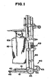
Figure 1 is a perspective view of a lift and flexible bag, viewed generally from the side; -
Figure 2 is a perspective view, viewed generally from in front, of the flexible bag in position on a fixture; -
Figure 3 is a more detailed view of the fixture shown inFigure 2 ; -
Figure 4 is a cross-sectional view of the fixture shown inFigure 3 , taken generally along the lines 4-4; -
Figure 5 is a perspective view of a guide; -
Figure 6 is a perspective view of the guide in position in the opening of the flexible bag; -
Figure 7 is another embodiment of a fixture for use with the present invention; -
Figure 8a is a cross-sectional view of the fixture shown inFigure 7 taken generally along the lines 8a-8a; -
Figure 8b is a cross-sectional view of the fixture shown inFigure 7 taken generally along the lines 8b-8b; -
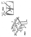
Figure 9 is a top plan view of another embodiment of the fixture; -
Figure 10 is a perspective view of the fixture shown inFigure 9 , with a base; -
Figure 11 is a side elevational view of another embodiment of a fixture; and -
Figure 12 is a cross-sectional view of the fixture shown inFigure 11 , taken generally along the lines 12-12. - Referring to the drawings, where like numerals represent like parts throughout the several views, there is generally disclosed at 10 a flexible bag. The
bag 10 is preferably a two-part bag, comprising an inner layer 10a and is made from a suitable plastic, such as polyethylene. Anouter layer 10b is made from a suitable material such as what is referred to as a fabric bag construction material, such as a woven polyethylene or woven polypropylene. The inner bag 10a is preferably closed with a tie wrap, as is theouter bag 10b. Thebag 10 has an opening 11 through which a powder paint is dispensed. The bag may be any suitable size, such as a size equivalent to a 30. or 53-gallon (113-208 liter) drum. The weight of abag 10 filled with a powder paint would typically weigh between 200-300 pounds (91-136 kg). The bags may then be placed on a pallet and shrink wrap applied to maintain multiple bags on one pallet. Theouter bag 10b may have a suitable construction such as a base 12 (Fig. 4 ) that is circular and is stitched or sewn to aside panel 13 to form thebag 10b. Other suitable construction or combination may be utilized to result in theflexible bag 10. Anattachment member 20 is operatively connected to thebag 10. One example of anattachment member 20 is shown as a length ofwebbing 21 that is operatively connected by suitable means, such as stitching, to theouter layer 10b ofbag 10. The webbing extends above the top of thebag 10 and forms a loop. One way of constructing a loop 21 a is to utilize a length of webbing and secure both ends to thebag 10, thus leaving a loop 21a that may be utilized in the handling of thebag 10. It is of course understood that othersuitable attachment members 20 may also be utilized. Some examples of which are the use of Velcro®, grommets, tubes or sleeves. - As seen in
Figure 5 , atube guide 30 is shown. Thetube guide 30 has a generally planar top 31 in which threeopenings 31a are formed. Threecylindrical members 31b are suitably attached proximate theopenings 31a and extend generally downward from the planar top 31, although it is understood that they could also extend upward. Further, it is recognized tubes are optional as just theopenings 31 a provide some guidance forfeed tubes 32. Thecylindrical members 31b have bores 31c that are sized to receivefeed tubes 32. Thefeed tubes 32 are connected to a suitable apparatus, well known in the art, that provides for aspiration of the powder paint contained in thebag 10. The planar top 31 has fourattachment openings 33 that are utilized to position the tube guide over the opening 11. Achain 34 has hooks 35 at each of the chains ends and the hooks 35 are fitted in theattachment openings 33. Thechains 34 are looped over a device, to be described more fully hereafter, to support thetube guide 30 in position. It is understood other suitable methods may be used to support thetube guide 30. - A
material lift 40 is shown inFigures 1 and2 . Thematerial lift 40 may be any suitable lift such as a Genie® lift supplied by Genie® United States, Redmond, Washington. Thematerial lift 40 includes a base having twoextensions 41 on which are mounted, at their front ends,wheels 42.Rear wheels 43 are mounted on asuitable axle 44. On theupright frame 45 is mounted amoveable assembly 46.Support arms 47 extending generally horizontal from themoveable assembly 46. On eachsupport arm 47 is secured ahook 48. Themoveable assembly 46 is moved up and down by a hand crank 49 which utilizes suitable gears and pulleys, as is well-known in the art. While a manually moveable material lift in both the horizontal and vertical orientations is shown, it is understood that mechanized versions, as well as other suitable material lifts may also be utilized. - A first embodiment of a
fixture 50 is shown inFigures 2 ,3 and4 . Thefixture 50 includes a base 51 that includes afirst side plate 52 and asecond side plate 53. Ahousing 54 includes afront plate 55 operatively connected to aback plate 56. The bottom portion of the ends of theplates side plates housing 54 forms a V shape that is adapted and configured to receive abag 10. As can be seen, the cross section of thehousing 54 decreases when measured along a vertical axis toward the ground. An air drivenvibratory motor 57 is operatively connected to thehousing 54. The operation of such amotor 57 is well known in the art. Themotor 57 vibrates the housing, and thereby the powder paint inside of thebag 10 to aid in the dispensing of the powder paint.Figure 4 shows abag 10 that has been positioned in thefixture 50. As can be seen, the lower portion of the bag deforms and generally conforms to the shape of thehousing 54. - Another embodiment is a
fixture 60, as shown inFigures 7 and 8 . Thefixture 60 has abase 61, that includes afirst side plate 62 and asecond side plate 63. Ahousing 64 has an open top adapted and configured to receive thebag 10. Further, thehousing 64 has an open bottom through which thebag 10 may extend. Front andback plates side plates 67 and 68. Theplates 65 through 68 are all operatively connected and generally form an inverted truncated pyramid. Again, thehousing 54 has a smaller, decreasing cross-section when measured along a vertical axis toward the ground. As can be seen inFigure 8a , thebag 10 will generally conform to the shape of thehousing 64 and will also have a generally decreasing cross-section when measured along a vertical axis toward the ground. - A third embodiment shows a
fixture 70 inFigures 9 and10 . Thefixture 70 is generally conical and has a base 71. the base 71 is generally, rectangular and has an opening that is sized and configured to receive the conical shape formed by thehousing 74. Thehousing 74 includes aside plate 75 that is conical and has an opening 74a at the top that is adapted and configured to receive thebag 10 and may also optionally have anopening 74b at the bottom through which thebag 10 may extend. Again, thehousing 54 has a decreasingly smaller cross-section when measured along a vertical axis toward the ground and therefore when thebag 10, is positioned in thehousing 74, the bag will generally conform to thehousing 74 and the bag will likewise have a decreasing cross-section when measured along a vertical axis toward the ground. - Referring to
Figures 11 and 12 , another embodiment shows afixture 80. Thefixture 80 includes asemi-circular wall 85 operatively connected to a generallyplanar base 86. Thefixture 80 may then be tilted from the horizontal at a suitable angle such as 45°. When in this operating position, and abag 10 is positioned in thefixture 80, the fixture will have a decreasing cross-section when measured along a vertical axis toward the ground as will thebag 10 as it again generally conforms to the shape of thewall 85. A suitable mechanism may be used to tilt thefixture 80, similar to that used inU.S. Patent No. 4,505,623 , such mechanisms being known in the art. In addition, it is understood that thefixture motor 57. - In one operative embodiment, the
material lift 40 is moved to a location where filledbags 10 are kept. Typically, the filled bags are shipped on a pallet. The inner bag 10a is filled with a powder paint. Theextensions 41 are moved underneath the pallet and thehooks 48 are positioned over the loops 21 a. The loops 21a are then lifted and placed on thehooks 48. Then, themoveable assembly 46 is raised, thereby lifting thebag 10 off of a pallet or other storage member. Thematerial lift 40 andbag 10 are then moved in positionproximate feed tubes 32 that are used in the electrostatic finishing. Thefeed tubes 32 are connected to suitable vacuum sources that allow for the aspiration of the powder paint into a hopper of a suitable electrostatic finishing apparatus, such apparatuses being well known in the art. Prior to operation, atube guide 30 may be supported over the opening 11 of thebag 10. As shown inFigures 2 and6 , thetube guide 30 may be supported bychains 34 that are connected to thesupport arms 47. The tube guide allows for the proper positioning of thefeed tubes 32. If desired, the chains could be supported in other manners. For instance, it may be desirable to be able to position thetube guide 30 above thehooks 48 while removing thebag 10. A rod could be secured to one of thearms 47 and the rod would extend upward and then over to proximate the center line and form a hook. Thechains 34 would then have to be longer, but could be supported by that hook. Then, when it is desired to add or remove abag 10, the chains could be removed from the hook and then reconnected, thereby shortening the chains and bringing thetube guide 30 to a position above thehooks 48. Forfixtures extensions 41 are moved into position inside of thebase bag 10 over thefixtures moveable assembly 46 is then lowered so that thebag 10 is lowered into thehousing bag 10 then conforms to the increasingly smaller cross-section of thehousing support arms 47 through the hooks48. As previously started, other ways of supporting thebag 10 may also be utilized. By having thefeed tubes 32 now in position, the powder paint is now ready to be aspirated to the hopper of the electrostatic finishing equipment or other suitable end use. As the powder paint is dispensed, thetubes 32 move downward, by gravity, to the bottom of thebag 10. The smaller decreasing cross-section allows for the dispensing of more of the powder paint, and therefore less waste. The smaller cross-section provides for a more localized area in which thefeed tubes 32 enter, to thereby aspirate more of the remaining powder paint. - The operation utilizing the
fixture 70 is similar except theextensions 41 are positioned on the outside of the base 71. - In using the fixtures shown in
Figures 11 and 12 , thebag 10 may be similarly moved by use of thematerial lift 40 from the pallet area to the position proximate thefeed tubes 32. However, thewall 85 provides for support for thebag 10 and it is therefore not necessary to use thematerial lift 40 for support during the aspiration of the powder paint. Thebag 10 may be placed in thefixture 80 when the fixture is either vertical, or tilted, as shown inFigure 11 . If placed in thefixture 80 while it is vertical, the fixture is then typically tilted after the bag is in position. Alternately, the fixtures could already be tilted before thebag 10 is placed in position. The tiltedfixture 80 again provides for a smaller, decreasing cross-section when measured along the vertical axis towards the ground. Since the bag is flexible and generally conforms to the shape of the fixture, the bag will have a similar, decreasing cross-section when measured along the vertical axis towards the ground. Thetube guide 30, if utilized, would then have to be supported on another structure, such as on thewall 85, if thematerial lift 40 is not used. However, it is understood that thematerial lift 40 could still remain in position, even though not necessary to support thebag 10. - In the embodiments that utilize
fixtures material lift 40 is utilized to maintain theflexible bag 10 in a vertical position during aspiration. This is optional when using thefixture 80. When usingfixtures flexible bag 10 and it is the housing of thefixtures bag 10 conforms. Thefixture 80 does not substantially change the shape of thebag 10. However, when it is in a tilted position, thebag 10 still has a decreasingly smaller cross-section when measured along a vertical axis towards the ground. Thefixtures fixture 80 may be positioned in a single position and placed on the ground similar tofixtures fixture 80 will be positioned in another device that allows thefixture 80 to be tilted from a vertical position to the position as shown inFigure 11 . - With respect to
fixtures feed tubes 32 to the smaller cross-section, thereby assisting in more fully emptying theflexible bag 10. It is understood that when the lower portion of thebag 10 generally conforms to the shape of the decreasing cross section of the fixture, it is not necessarily the lowest portion. For instance, with respect tofixtures bag 10 may actually extend below the walls of fixture, as shown inFigure 8 . - In addition, if the
fixture fixtures bag 10. One way of doing so would be to have straps across theextensions 41. As viewed inFigure 10 , one strap would be in front of thefixture 70 proximately adjacent thewheels 42 and the other would be behind thefixture 70 and still extend between theextensions 41. This would prevent movement in a direction parallel to theextensions 41. Theextensions 41 prevent significant movement in the opposite direction. The straps or confinement feature will keep the vibratory base from moving and keep the base more underneath the center of thebag 10, thereby aiding in aspirating the delivery of the finely divided particulate out of the bag. - The above specification, examples and data provide a complete description of the manufacture and use of the composition of the invention. Since many embodiments of the invention can be made without departing from the scope of the invention, the invention resides in the claims hereinafter appended.
Claims (10)
- An apparatus for delivering powder paint comprising:(a) at least one feed tube (32);(b) a flexible bag (10) containing powder paint having a top configured for receiving the at least one feed tube (32);(c) an electrostatic finishing apparatus operatively connected to the at least one feed tube;(d) a support apparatus having at least one support member capable of maintaining the flexible bag in a vertical position;(e) at least one attachment member (20) operatively connected to the bag (10) and adapted and configured to be secured to the support member;(f) a vacuum source operatively connected to the at least one feed tube (32);(g) a tube guide (30), positioned proximate the open top of the bag (10), the tube guide (30) configured and arranged to guide the at least one feed tube (32) into the bag (10); and(h) a fixture (50, 60, 70, 80) having a receiving member over which the bag (10) is positioned, the fixture (50, 60, 70, 80) being shaped to conform the bag to a smaller cross section at a lower level, the fixture (50, 60, 70, 80) is a vibrating fixture, wherein the powder paint is free flowing, wherein the receiving member, when the apparatus is being used to aspirate powder paint, position at least the lower portion of the bag (10), and wherein the apparatus facilitates powder paint delivery by aspiration through the at least one feed tube (32) to the electrostatic finishing apparatus,characterized in the support apparatus having at least one support member comprising an upright frame (45) with a moveable assembly from which support arms (47) extend generally horizontal.
- The apparatus of claim 1, wherein the fixture (50, 60, 70, 80) is conical in shape.
- The apparatus of claim 1, wherein the fixture (50, 60, 70, 80) has one or more sides generally angled downward and inward
- The apparatus of claim 1, wherein the fixture (50,60, 70, 80) is generally V-shaped.
- The apparatus of claim 1, further comprising the support apparatus being horizontally moveable.
- The apparatus of claim 1, further comprising the support member being vertically moveable.
- The apparatus of claim 1, wherein the bag (10) has an inner layer and an outer layer.
- The apparatus of claim 1, wherein the inner layer (10a) is a plastic layer and the outer layer (10b) is woven.
- A method, comprising:(a) providing a flexible bag (10) containing powder paint;(b) supporting the bag (10) having at least one attachment member (20) operatively connected to the bag (10) using a moveable lifting apparatus having a support member for attachment to the bag (10) by the attachment member (20), the support member comprising an upright frame (45) with a moveable assembly from which support arms (47) extend generally horizontal;(c) raising the support member, thereby lifting the bag (10);(d) moving the lifting apparatus and bag (10) from a storage area to proximate the feed tube (32);(e) lowering the bag (10) on top of a fixture (50, 60, 70, 80);(f) positioning the bag (10) adjacent a fixture (50, 60, 70, 80) sized and configured to receive at least a lower portion of the flexible bag (10) and having a side that forms a shape when in its operating position having a smaller, decreasing cross-section when measured along a vertical axis towards the ground;(g) positioning an aspiration feed tube into the bag (10);(h) aspirating the powder paint through the tube to an electrostatic finishing apparatus, wherein as the powder paint level is decreased the tube is permitted to move to a lower position in the bag and is directed towards the lowermost portion of the bag by the side;(i) vibrating the fixture (50, 60, 70, 80), wherein the powder paint is assisted in moving to a lower portion of the bag (10); and ,(j) providing a tube guide (30) positioned proximate the open top of the bag, the tube guide (30) configured and arranged to guide the aspiration feed tube into the bag (10).
- The method of claim 9, further comprising:(a) supporting the bag (10) during aspiration with the support member; and(b) moving the lifting apparatus and bag (10) away from the feed tube (32).
Priority Applications (1)
| Application Number | Priority Date | Filing Date | Title |
|---|---|---|---|
| PL06847554T PL1976641T3 (en) | 2006-01-06 | 2006-12-11 | Method and apparatus for powder delivery system |
Applications Claiming Priority (3)
| Application Number | Priority Date | Filing Date | Title |
|---|---|---|---|
| US75711506P | 2006-01-06 | 2006-01-06 | |
| US11/526,979 US7963728B2 (en) | 2006-01-06 | 2006-09-26 | Method and apparatus for powder delivery system |
| PCT/US2006/047186 WO2007081475A1 (en) | 2006-01-06 | 2006-12-11 | Method and apparatus for powder delivery system |
Publications (2)
| Publication Number | Publication Date |
|---|---|
| EP1976641A1 EP1976641A1 (en) | 2008-10-08 |
| EP1976641B1 true EP1976641B1 (en) | 2011-07-13 |
Family
ID=38055670
Family Applications (1)
| Application Number | Title | Priority Date | Filing Date |
|---|---|---|---|
| EP06847554A Not-in-force EP1976641B1 (en) | 2006-01-06 | 2006-12-11 | Method and apparatus for powder delivery system |
Country Status (6)
| Country | Link |
|---|---|
| US (1) | US7963728B2 (en) |
| EP (1) | EP1976641B1 (en) |
| CN (1) | CN101356013B (en) |
| AT (1) | ATE516085T1 (en) |
| PL (1) | PL1976641T3 (en) |
| WO (1) | WO2007081475A1 (en) |
Families Citing this family (9)
| Publication number | Priority date | Publication date | Assignee | Title |
|---|---|---|---|---|
| US7758954B2 (en) * | 2005-08-18 | 2010-07-20 | James Hardie Technology Limited | Coated substrate having one or more cross-linked interfacial zones |
| US7694981B2 (en) * | 2007-03-20 | 2010-04-13 | The Boeing Company | Multiple use, transformable cart |
| CA2696569C (en) * | 2007-06-28 | 2016-05-31 | James Hardie Technology Limited | Paint formulation for building material |
| WO2009006324A1 (en) * | 2007-06-29 | 2009-01-08 | James Hardie International Finance B.V. | Multifunctional primers |
| US8602071B1 (en) * | 2011-08-12 | 2013-12-10 | Mark S. Eno | Bag filling assembly |
| ES2716880T3 (en) * | 2013-05-02 | 2019-06-17 | Purac Biochem Bv | Procedure of storage and / or transport of lactide particles |
| ES2637505T3 (en) * | 2014-04-24 | 2017-10-13 | Robatech Ag | Installation for the transport of a product of fine particles |
| US20160339738A1 (en) * | 2015-05-19 | 2016-11-24 | Emmet Kauffman | Stand for Holding Container at an Angle |
| US10926948B2 (en) * | 2017-05-24 | 2021-02-23 | Ilc Dover Ip, Inc. | Liner with lifting cradle |
Family Cites Families (35)
| Publication number | Priority date | Publication date | Assignee | Title |
|---|---|---|---|---|
| JPS5235439B2 (en) | 1973-07-19 | 1977-09-09 | ||
| US4113146A (en) * | 1974-04-11 | 1978-09-12 | Better Agricultural Goals Corporation | Disposable container for bulk materials |
| US4505623A (en) * | 1982-09-17 | 1985-03-19 | Nordson Corporation | Apparatus for transferring powder from bulk drums |
| US4480766A (en) * | 1982-09-24 | 1984-11-06 | Ibc Transport Containers, Ltd. | Bulk transport bag |
| GB8332059D0 (en) | 1983-12-01 | 1984-01-11 | Flomat Ltd | Materials handling equipment |
| EP0168974A3 (en) * | 1984-06-20 | 1987-02-04 | Bowater Packaging Limited | Lining for a flexible bulk container |
| US4913321A (en) * | 1988-08-08 | 1990-04-03 | Harry Abboud | Bulk particulate solids transport bag with gas assist unloading feature |
| US4966311A (en) * | 1988-11-29 | 1990-10-30 | Taylor Murland L | Bulk bag emptying apparatus and method |
| EP0450295A3 (en) * | 1990-04-04 | 1992-01-08 | Wagner International Ag | Fluidising and conveying device |
| US5271695A (en) * | 1990-07-07 | 1993-12-21 | Gema Volstatic Ag | Device for pneumatically feeding powder from a container |
| JPH0530286A (en) | 1991-07-23 | 1993-02-05 | Toshiba Corp | Picture reader |
| EP0534807B1 (en) * | 1992-04-30 | 1996-08-14 | Nordson Corporation | Method and apparatus for unloading powder from a container |
| JPH0624557A (en) | 1992-07-07 | 1994-02-01 | Nisshin Flour Milling Co Ltd | Delivery method for powder |
| US5382117A (en) * | 1994-03-28 | 1995-01-17 | Henkel Kommanditgesellschaft Auf Aktien | Apparatus for holding a powder container |
| US5667352A (en) * | 1994-04-18 | 1997-09-16 | Genie Industries | Locking system for extension members on portable lifts |
| US5938338A (en) * | 1994-09-09 | 1999-08-17 | Rohm & Haas Company | Recycleable bulk bag containers |
| US5507602A (en) * | 1994-10-14 | 1996-04-16 | J. M. Huber Corporation | Powder transfer from supersack containers and dispersion into a homogeneous slurry |
| DE19506538C2 (en) | 1995-02-24 | 1999-09-16 | Helmut Haas | Powder removal device |
| WO1997012823A1 (en) * | 1995-10-02 | 1997-04-10 | Klaus Wilhelm | Suction device for bulk material containers |
| DE19628429C2 (en) * | 1996-07-15 | 1999-03-11 | Klaus Wilhelm | Emptying device for free-flowing bulk goods |
| DE19641982C1 (en) * | 1996-10-11 | 1998-05-20 | Degussa | Emptying device for bulk bags and their use |
| US5975351A (en) * | 1997-03-26 | 1999-11-02 | Flexcon & Systems, Inc. | Method and system for stabilizing bulk bags during emptying |
| CA2205273A1 (en) * | 1997-05-13 | 1998-11-13 | William Shackleton | Upstanding lifting strap for a bulk container |
| DE19741108A1 (en) | 1997-09-18 | 1999-03-25 | Delta P Vakuum Und Niederdruck | Folding frame for flexible intermediate bulk container holding products |
| US6398462B1 (en) * | 1998-06-03 | 2002-06-04 | Nordson Corporation | Powder transfer apparatus having powder fluidizing tube |
| US6186360B1 (en) * | 1998-11-20 | 2001-02-13 | Schenck Accurate, Inc. | Machine and method for unloading a bulk-material bag |
| US6533121B1 (en) * | 1999-04-26 | 2003-03-18 | Grayling Industries, Inc. | Palletized bulk bag |
| US6499584B1 (en) * | 1999-10-26 | 2002-12-31 | Merck & Co., Inc. | Method and apparatus for handling bulk bags |
| DE20100219U1 (en) * | 2001-01-08 | 2001-07-05 | Bothor Kerim Patrick | Device for receiving, transporting, controlled emptying and storage of flowable bulk goods in large-volume containers |
| US6923340B2 (en) * | 2003-02-27 | 2005-08-02 | The Young Industries, Inc. | System and method for storing, transporting and dispensing bulk particulate materials and dispensing apparatus therefor |
| US6830414B2 (en) * | 2003-03-27 | 2004-12-14 | General Motors Corporation | Canister powder paint delivery apparatus and method |
| US20040190799A1 (en) * | 2003-03-31 | 2004-09-30 | General Electric Company | Side discharge bag for flowable materials and method for dicharging flowable materials |
| US6979166B2 (en) * | 2003-05-15 | 2005-12-27 | Kellogg Company | Vacuum wand assembly for extracting a product from a container |
| US20050194405A1 (en) * | 2004-03-02 | 2005-09-08 | Kosich Mark M. | Bulk bag handling apparatus and method |
| DE102004015014A1 (en) | 2004-03-26 | 2005-10-13 | HELIOS Gerätebau für Kunststofftechnik GmbH | Method and device for emptying bulk material |
-
2006
- 2006-09-26 US US11/526,979 patent/US7963728B2/en not_active Expired - Fee Related
- 2006-12-11 EP EP06847554A patent/EP1976641B1/en not_active Not-in-force
- 2006-12-11 PL PL06847554T patent/PL1976641T3/en unknown
- 2006-12-11 WO PCT/US2006/047186 patent/WO2007081475A1/en active Application Filing
- 2006-12-11 CN CN2006800505300A patent/CN101356013B/en not_active Expired - Fee Related
- 2006-12-11 AT AT06847554T patent/ATE516085T1/en not_active IP Right Cessation
Also Published As
| Publication number | Publication date |
|---|---|
| US7963728B2 (en) | 2011-06-21 |
| CN101356013A (en) | 2009-01-28 |
| CN101356013B (en) | 2012-10-24 |
| EP1976641A1 (en) | 2008-10-08 |
| WO2007081475A1 (en) | 2007-07-19 |
| US20070169843A1 (en) | 2007-07-26 |
| PL1976641T3 (en) | 2011-12-30 |
| ATE516085T1 (en) | 2011-07-15 |
Similar Documents
| Publication | Publication Date | Title |
|---|---|---|
| EP1976641B1 (en) | Method and apparatus for powder delivery system | |
| US5415323A (en) | Dry mix dispensing apparatus and method | |
| US7244087B2 (en) | System and method for unloading bulk powder from large bulk containers | |
| US7140516B2 (en) | Device for large-volume containers | |
| JP2007131308A (en) | Container apparatus for delivering fertilizer | |
| US20090008410A1 (en) | Flexible silo apparatus having a top removable valve or flow control device | |
| US10737202B2 (en) | Assembly with pivotable hopper and shaker | |
| US5944455A (en) | Lifting assembly for use with a discharge device for flowable granular material | |
| US8529160B2 (en) | Bulk abrasive hopper | |
| JP2003246462A (en) | Device and method for metered dispensing of coating powder from powder bag | |
| AU2002231346A1 (en) | A system and method for unloading bulk powder from large bulk containers | |
| US7287946B2 (en) | Unloader for discharging dry materials from bulk bags | |
| WO1999057041A1 (en) | Bulk bag filler | |
| US6923340B2 (en) | System and method for storing, transporting and dispensing bulk particulate materials and dispensing apparatus therefor | |
| US9254935B2 (en) | Bulk material handling system and carrier therefor | |
| US20090001107A1 (en) | System and Method for Storing, Transporting and Dispensing Bulk Particulate Materials and Dispensing Apparatus Therefor | |
| KR20050119669A (en) | Side discharge bag for flowable materials and method for discharging flowable materials | |
| US4718464A (en) | Bag filling apparatus | |
| ES2369105T3 (en) | METHOD AND APPARATUS FOR A DUST SUPPLY SYSTEM. | |
| JP3170495U (en) | Fertilizer delivery container equipment | |
| US6276829B1 (en) | Transport bag | |
| MX2008008704A (en) | Method and apparatus for powder delivery system | |
| US20040118983A1 (en) | Apparatus for supporting a material bag | |
| WO2022258970A2 (en) | Bulk bag discharging apparatus | |
| CA2219041A1 (en) | Dry mortar mix transportable silo |
Legal Events
| Date | Code | Title | Description |
|---|---|---|---|
| PUAI | Public reference made under article 153(3) epc to a published international application that has entered the european phase |
Free format text: ORIGINAL CODE: 0009012 |
|
| 17P | Request for examination filed |
Effective date: 20080804 |
|
| AK | Designated contracting states |
Kind code of ref document: A1 Designated state(s): AT BE BG CH CY CZ DE DK EE ES FI FR GB GR HU IE IS IT LI LT LU LV MC NL PL PT RO SE SI SK TR |
|
| 17Q | First examination report despatched |
Effective date: 20090429 |
|
| RAP1 | Party data changed (applicant data changed or rights of an application transferred) |
Owner name: VALSPAR SOURCING, INC. |
|
| GRAP | Despatch of communication of intention to grant a patent |
Free format text: ORIGINAL CODE: EPIDOSNIGR1 |
|
| DAX | Request for extension of the european patent (deleted) | ||
| GRAS | Grant fee paid |
Free format text: ORIGINAL CODE: EPIDOSNIGR3 |
|
| GRAA | (expected) grant |
Free format text: ORIGINAL CODE: 0009210 |
|
| AK | Designated contracting states |
Kind code of ref document: B1 Designated state(s): AT BE BG CH CY CZ DE DK EE ES FI FR GB GR HU IE IS IT LI LT LU LV MC NL PL PT RO SE SI SK TR |
|
| REG | Reference to a national code |
Ref country code: GB Ref legal event code: FG4D |
|
| REG | Reference to a national code |
Ref country code: CH Ref legal event code: EP |
|
| REG | Reference to a national code |
Ref country code: IE Ref legal event code: FG4D |
|
| REG | Reference to a national code |
Ref country code: DE Ref legal event code: R096 Ref document number: 602006023117 Country of ref document: DE Effective date: 20110908 |
|
| REG | Reference to a national code |
Ref country code: NL Ref legal event code: VDEP Effective date: 20110713 |
|
| REG | Reference to a national code |
Ref country code: ES Ref legal event code: FG2A Ref document number: 2369105 Country of ref document: ES Kind code of ref document: T3 Effective date: 20111125 |
|
| REG | Reference to a national code |
Ref country code: PL Ref legal event code: T3 |
|
| REG | Reference to a national code |
Ref country code: AT Ref legal event code: MK05 Ref document number: 516085 Country of ref document: AT Kind code of ref document: T Effective date: 20110713 |
|
| PG25 | Lapsed in a contracting state [announced via postgrant information from national office to epo] |
Ref country code: LT Free format text: LAPSE BECAUSE OF FAILURE TO SUBMIT A TRANSLATION OF THE DESCRIPTION OR TO PAY THE FEE WITHIN THE PRESCRIBED TIME-LIMIT Effective date: 20110713 Ref country code: NL Free format text: LAPSE BECAUSE OF FAILURE TO SUBMIT A TRANSLATION OF THE DESCRIPTION OR TO PAY THE FEE WITHIN THE PRESCRIBED TIME-LIMIT Effective date: 20110713 Ref country code: IS Free format text: LAPSE BECAUSE OF FAILURE TO SUBMIT A TRANSLATION OF THE DESCRIPTION OR TO PAY THE FEE WITHIN THE PRESCRIBED TIME-LIMIT Effective date: 20111113 Ref country code: SE Free format text: LAPSE BECAUSE OF FAILURE TO SUBMIT A TRANSLATION OF THE DESCRIPTION OR TO PAY THE FEE WITHIN THE PRESCRIBED TIME-LIMIT Effective date: 20110713 Ref country code: BE Free format text: LAPSE BECAUSE OF FAILURE TO SUBMIT A TRANSLATION OF THE DESCRIPTION OR TO PAY THE FEE WITHIN THE PRESCRIBED TIME-LIMIT Effective date: 20110713 Ref country code: PT Free format text: LAPSE BECAUSE OF FAILURE TO SUBMIT A TRANSLATION OF THE DESCRIPTION OR TO PAY THE FEE WITHIN THE PRESCRIBED TIME-LIMIT Effective date: 20111114 Ref country code: FI Free format text: LAPSE BECAUSE OF FAILURE TO SUBMIT A TRANSLATION OF THE DESCRIPTION OR TO PAY THE FEE WITHIN THE PRESCRIBED TIME-LIMIT Effective date: 20110713 |
|
| PGFP | Annual fee paid to national office [announced via postgrant information from national office to epo] |
Ref country code: CZ Payment date: 20111129 Year of fee payment: 6 |
|
| PG25 | Lapsed in a contracting state [announced via postgrant information from national office to epo] |
Ref country code: SI Free format text: LAPSE BECAUSE OF FAILURE TO SUBMIT A TRANSLATION OF THE DESCRIPTION OR TO PAY THE FEE WITHIN THE PRESCRIBED TIME-LIMIT Effective date: 20110713 Ref country code: GR Free format text: LAPSE BECAUSE OF FAILURE TO SUBMIT A TRANSLATION OF THE DESCRIPTION OR TO PAY THE FEE WITHIN THE PRESCRIBED TIME-LIMIT Effective date: 20111014 Ref country code: AT Free format text: LAPSE BECAUSE OF FAILURE TO SUBMIT A TRANSLATION OF THE DESCRIPTION OR TO PAY THE FEE WITHIN THE PRESCRIBED TIME-LIMIT Effective date: 20110713 Ref country code: CY Free format text: LAPSE BECAUSE OF FAILURE TO SUBMIT A TRANSLATION OF THE DESCRIPTION OR TO PAY THE FEE WITHIN THE PRESCRIBED TIME-LIMIT Effective date: 20110713 Ref country code: LV Free format text: LAPSE BECAUSE OF FAILURE TO SUBMIT A TRANSLATION OF THE DESCRIPTION OR TO PAY THE FEE WITHIN THE PRESCRIBED TIME-LIMIT Effective date: 20110713 |
|
| PG25 | Lapsed in a contracting state [announced via postgrant information from national office to epo] |
Ref country code: SK Free format text: LAPSE BECAUSE OF FAILURE TO SUBMIT A TRANSLATION OF THE DESCRIPTION OR TO PAY THE FEE WITHIN THE PRESCRIBED TIME-LIMIT Effective date: 20110713 |
|
| PLBE | No opposition filed within time limit |
Free format text: ORIGINAL CODE: 0009261 |
|
| STAA | Information on the status of an ep patent application or granted ep patent |
Free format text: STATUS: NO OPPOSITION FILED WITHIN TIME LIMIT |
|
| PG25 | Lapsed in a contracting state [announced via postgrant information from national office to epo] |
Ref country code: EE Free format text: LAPSE BECAUSE OF FAILURE TO SUBMIT A TRANSLATION OF THE DESCRIPTION OR TO PAY THE FEE WITHIN THE PRESCRIBED TIME-LIMIT Effective date: 20110713 Ref country code: RO Free format text: LAPSE BECAUSE OF FAILURE TO SUBMIT A TRANSLATION OF THE DESCRIPTION OR TO PAY THE FEE WITHIN THE PRESCRIBED TIME-LIMIT Effective date: 20110713 |
|
| 26N | No opposition filed |
Effective date: 20120416 |
|
| PG25 | Lapsed in a contracting state [announced via postgrant information from national office to epo] |
Ref country code: DK Free format text: LAPSE BECAUSE OF FAILURE TO SUBMIT A TRANSLATION OF THE DESCRIPTION OR TO PAY THE FEE WITHIN THE PRESCRIBED TIME-LIMIT Effective date: 20110713 |
|
| PG25 | Lapsed in a contracting state [announced via postgrant information from national office to epo] |
Ref country code: MC Free format text: LAPSE BECAUSE OF NON-PAYMENT OF DUE FEES Effective date: 20111231 |
|
| REG | Reference to a national code |
Ref country code: CH Ref legal event code: PL |
|
| REG | Reference to a national code |
Ref country code: DE Ref legal event code: R097 Ref document number: 602006023117 Country of ref document: DE Effective date: 20120416 |
|
| REG | Reference to a national code |
Ref country code: IE Ref legal event code: MM4A |
|
| PG25 | Lapsed in a contracting state [announced via postgrant information from national office to epo] |
Ref country code: CH Free format text: LAPSE BECAUSE OF NON-PAYMENT OF DUE FEES Effective date: 20111231 Ref country code: LI Free format text: LAPSE BECAUSE OF NON-PAYMENT OF DUE FEES Effective date: 20111231 Ref country code: IE Free format text: LAPSE BECAUSE OF NON-PAYMENT OF DUE FEES Effective date: 20111211 |
|
| PG25 | Lapsed in a contracting state [announced via postgrant information from national office to epo] |
Ref country code: LU Free format text: LAPSE BECAUSE OF NON-PAYMENT OF DUE FEES Effective date: 20111211 |
|
| PG25 | Lapsed in a contracting state [announced via postgrant information from national office to epo] |
Ref country code: BG Free format text: LAPSE BECAUSE OF FAILURE TO SUBMIT A TRANSLATION OF THE DESCRIPTION OR TO PAY THE FEE WITHIN THE PRESCRIBED TIME-LIMIT Effective date: 20111013 |
|
| PG25 | Lapsed in a contracting state [announced via postgrant information from national office to epo] |
Ref country code: CZ Free format text: LAPSE BECAUSE OF NON-PAYMENT OF DUE FEES Effective date: 20121211 |
|
| PG25 | Lapsed in a contracting state [announced via postgrant information from national office to epo] |
Ref country code: TR Free format text: LAPSE BECAUSE OF FAILURE TO SUBMIT A TRANSLATION OF THE DESCRIPTION OR TO PAY THE FEE WITHIN THE PRESCRIBED TIME-LIMIT Effective date: 20110713 |
|
| PG25 | Lapsed in a contracting state [announced via postgrant information from national office to epo] |
Ref country code: HU Free format text: LAPSE BECAUSE OF FAILURE TO SUBMIT A TRANSLATION OF THE DESCRIPTION OR TO PAY THE FEE WITHIN THE PRESCRIBED TIME-LIMIT Effective date: 20110713 |
|
| REG | Reference to a national code |
Ref country code: FR Ref legal event code: PLFP Year of fee payment: 10 |
|
| REG | Reference to a national code |
Ref country code: FR Ref legal event code: PLFP Year of fee payment: 11 |
|
| PG25 | Lapsed in a contracting state [announced via postgrant information from national office to epo] |
Ref country code: IT Free format text: LAPSE BECAUSE OF NON-PAYMENT OF DUE FEES Effective date: 20151211 |
|
| PG25 | Lapsed in a contracting state [announced via postgrant information from national office to epo] |
Ref country code: IT Free format text: LAPSE BECAUSE OF NON-PAYMENT OF DUE FEES Effective date: 20151211 |
|
| PGRI | Patent reinstated in contracting state [announced from national office to epo] |
Ref country code: IT Effective date: 20170710 |
|
| REG | Reference to a national code |
Ref country code: FR Ref legal event code: PLFP Year of fee payment: 12 |
|
| REG | Reference to a national code |
Ref country code: ES Ref legal event code: PC2A Owner name: SWIMC LLC Effective date: 20181015 |
|
| PGFP | Annual fee paid to national office [announced via postgrant information from national office to epo] |
Ref country code: PL Payment date: 20181121 Year of fee payment: 13 |
|
| PGFP | Annual fee paid to national office [announced via postgrant information from national office to epo] |
Ref country code: FR Payment date: 20181226 Year of fee payment: 13 Ref country code: GB Payment date: 20181227 Year of fee payment: 13 |
|
| REG | Reference to a national code |
Ref country code: DE Ref legal event code: R082 Ref document number: 602006023117 Country of ref document: DE Representative=s name: DENNEMEYER & ASSOCIATES S.A., DE Ref country code: DE Ref legal event code: R081 Ref document number: 602006023117 Country of ref document: DE Owner name: SWIMC LLC, CLEVELAND, US Free format text: FORMER OWNER: THE SHERWIN-WILLIAMS COMPANY, CLEVELAND, OHIO, US Ref country code: DE Ref legal event code: R081 Ref document number: 602006023117 Country of ref document: DE Owner name: SWIMC LLC, CLEVELAND, US Free format text: FORMER OWNER: VALSPAR SOURCING, INC., MINNEAPOLIS, MINN., US |
|
| PGFP | Annual fee paid to national office [announced via postgrant information from national office to epo] |
Ref country code: ES Payment date: 20190102 Year of fee payment: 13 Ref country code: DE Payment date: 20181231 Year of fee payment: 13 Ref country code: IT Payment date: 20181220 Year of fee payment: 13 |
|
| REG | Reference to a national code |
Ref country code: GB Ref legal event code: 732E Free format text: REGISTERED BETWEEN 20190404 AND 20190410 |
|
| REG | Reference to a national code |
Ref country code: GB Ref legal event code: 732E Free format text: REGISTERED BETWEEN 20190411 AND 20190417 |
|
| REG | Reference to a national code |
Ref country code: DE Ref legal event code: R119 Ref document number: 602006023117 Country of ref document: DE |
|
| GBPC | Gb: european patent ceased through non-payment of renewal fee |
Effective date: 20191211 |
|
| PG25 | Lapsed in a contracting state [announced via postgrant information from national office to epo] |
Ref country code: FR Free format text: LAPSE BECAUSE OF NON-PAYMENT OF DUE FEES Effective date: 20191231 Ref country code: IT Free format text: LAPSE BECAUSE OF NON-PAYMENT OF DUE FEES Effective date: 20191211 Ref country code: GB Free format text: LAPSE BECAUSE OF NON-PAYMENT OF DUE FEES Effective date: 20191211 Ref country code: DE Free format text: LAPSE BECAUSE OF NON-PAYMENT OF DUE FEES Effective date: 20200701 |
|
| REG | Reference to a national code |
Ref country code: ES Ref legal event code: FD2A Effective date: 20210601 |
|
| PG25 | Lapsed in a contracting state [announced via postgrant information from national office to epo] |
Ref country code: ES Free format text: LAPSE BECAUSE OF NON-PAYMENT OF DUE FEES Effective date: 20191212 |
|
| PG25 | Lapsed in a contracting state [announced via postgrant information from national office to epo] |
Ref country code: PL Free format text: LAPSE BECAUSE OF NON-PAYMENT OF DUE FEES Effective date: 20191211 |