EP1976469B1 - Device and method for calibrating a laser system - Google Patents
Device and method for calibrating a laser system Download PDFInfo
- Publication number
- EP1976469B1 EP1976469B1 EP06809150A EP06809150A EP1976469B1 EP 1976469 B1 EP1976469 B1 EP 1976469B1 EP 06809150 A EP06809150 A EP 06809150A EP 06809150 A EP06809150 A EP 06809150A EP 1976469 B1 EP1976469 B1 EP 1976469B1
- Authority
- EP
- European Patent Office
- Prior art keywords
- laser beam
- laser
- calibration member
- focal point
- calibration
- Prior art date
- Legal status (The legal status is an assumption and is not a legal conclusion. Google has not performed a legal analysis and makes no representation as to the accuracy of the status listed.)
- Active
Links
Images


Classifications
-
- A—HUMAN NECESSITIES
- A61—MEDICAL OR VETERINARY SCIENCE; HYGIENE
- A61F—FILTERS IMPLANTABLE INTO BLOOD VESSELS; PROSTHESES; DEVICES PROVIDING PATENCY TO, OR PREVENTING COLLAPSING OF, TUBULAR STRUCTURES OF THE BODY, e.g. STENTS; ORTHOPAEDIC, NURSING OR CONTRACEPTIVE DEVICES; FOMENTATION; TREATMENT OR PROTECTION OF EYES OR EARS; BANDAGES, DRESSINGS OR ABSORBENT PADS; FIRST-AID KITS
- A61F9/00—Methods or devices for treatment of the eyes; Devices for putting in contact-lenses; Devices to correct squinting; Apparatus to guide the blind; Protective devices for the eyes, carried on the body or in the hand
- A61F9/007—Methods or devices for eye surgery
- A61F9/008—Methods or devices for eye surgery using laser
-
- A—HUMAN NECESSITIES
- A61—MEDICAL OR VETERINARY SCIENCE; HYGIENE
- A61F—FILTERS IMPLANTABLE INTO BLOOD VESSELS; PROSTHESES; DEVICES PROVIDING PATENCY TO, OR PREVENTING COLLAPSING OF, TUBULAR STRUCTURES OF THE BODY, e.g. STENTS; ORTHOPAEDIC, NURSING OR CONTRACEPTIVE DEVICES; FOMENTATION; TREATMENT OR PROTECTION OF EYES OR EARS; BANDAGES, DRESSINGS OR ABSORBENT PADS; FIRST-AID KITS
- A61F9/00—Methods or devices for treatment of the eyes; Devices for putting in contact-lenses; Devices to correct squinting; Apparatus to guide the blind; Protective devices for the eyes, carried on the body or in the hand
- A61F9/007—Methods or devices for eye surgery
- A61F9/008—Methods or devices for eye surgery using laser
- A61F9/00825—Methods or devices for eye surgery using laser for photodisruption
-
- A—HUMAN NECESSITIES
- A61—MEDICAL OR VETERINARY SCIENCE; HYGIENE
- A61B—DIAGNOSIS; SURGERY; IDENTIFICATION
- A61B17/00—Surgical instruments, devices or methods
- A61B2017/00681—Aspects not otherwise provided for
- A61B2017/00707—Dummies, phantoms; Devices simulating patient or parts of patient
- A61B2017/00712—Dummies, phantoms; Devices simulating patient or parts of patient simulating mathematical properties, e.g. for testing of positioning in the isocentre or focus
-
- A—HUMAN NECESSITIES
- A61—MEDICAL OR VETERINARY SCIENCE; HYGIENE
- A61F—FILTERS IMPLANTABLE INTO BLOOD VESSELS; PROSTHESES; DEVICES PROVIDING PATENCY TO, OR PREVENTING COLLAPSING OF, TUBULAR STRUCTURES OF THE BODY, e.g. STENTS; ORTHOPAEDIC, NURSING OR CONTRACEPTIVE DEVICES; FOMENTATION; TREATMENT OR PROTECTION OF EYES OR EARS; BANDAGES, DRESSINGS OR ABSORBENT PADS; FIRST-AID KITS
- A61F9/00—Methods or devices for treatment of the eyes; Devices for putting in contact-lenses; Devices to correct squinting; Apparatus to guide the blind; Protective devices for the eyes, carried on the body or in the hand
- A61F9/007—Methods or devices for eye surgery
- A61F9/008—Methods or devices for eye surgery using laser
- A61F2009/00855—Calibration of the laser system
-
- A—HUMAN NECESSITIES
- A61—MEDICAL OR VETERINARY SCIENCE; HYGIENE
- A61F—FILTERS IMPLANTABLE INTO BLOOD VESSELS; PROSTHESES; DEVICES PROVIDING PATENCY TO, OR PREVENTING COLLAPSING OF, TUBULAR STRUCTURES OF THE BODY, e.g. STENTS; ORTHOPAEDIC, NURSING OR CONTRACEPTIVE DEVICES; FOMENTATION; TREATMENT OR PROTECTION OF EYES OR EARS; BANDAGES, DRESSINGS OR ABSORBENT PADS; FIRST-AID KITS
- A61F9/00—Methods or devices for treatment of the eyes; Devices for putting in contact-lenses; Devices to correct squinting; Apparatus to guide the blind; Protective devices for the eyes, carried on the body or in the hand
- A61F9/007—Methods or devices for eye surgery
- A61F9/008—Methods or devices for eye surgery using laser
- A61F2009/00861—Methods or devices for eye surgery using laser adapted for treatment at a particular location
- A61F2009/00872—Cornea
-
- A—HUMAN NECESSITIES
- A61—MEDICAL OR VETERINARY SCIENCE; HYGIENE
- A61F—FILTERS IMPLANTABLE INTO BLOOD VESSELS; PROSTHESES; DEVICES PROVIDING PATENCY TO, OR PREVENTING COLLAPSING OF, TUBULAR STRUCTURES OF THE BODY, e.g. STENTS; ORTHOPAEDIC, NURSING OR CONTRACEPTIVE DEVICES; FOMENTATION; TREATMENT OR PROTECTION OF EYES OR EARS; BANDAGES, DRESSINGS OR ABSORBENT PADS; FIRST-AID KITS
- A61F9/00—Methods or devices for treatment of the eyes; Devices for putting in contact-lenses; Devices to correct squinting; Apparatus to guide the blind; Protective devices for the eyes, carried on the body or in the hand
- A61F9/007—Methods or devices for eye surgery
- A61F9/008—Methods or devices for eye surgery using laser
- A61F9/00825—Methods or devices for eye surgery using laser for photodisruption
- A61F9/0084—Laser features or special beam parameters therefor
Definitions
- the present invention pertains generally to laser system calibration procedures. More particularly, the present invention relates to systems and methods for performing laser system calibration wherein the laser beam causes Laser Induced Optical Breakdown (LIOB) in a reference material.
- LIOB Laser Induced Optical Breakdown
- the present invention is particularly, but not exclusively, useful as a system and method for precise calibration of a laser system via the identification and measurement of locations where LIOB occurs in a reference material.
- the laser beam For a laser system used in ophthalmic surgery, it is critical that the laser beam be properly focused, and that the position of the beam's focal point with respect to the laser generating unit be known. Further, due to the curved nature of the cornea, a beam that is to be used in ophthalmic surgery must exhibit proper depth and avoid tilt and lateral displacement (decentration). Additionally, the focal point of the laser beam should have a substantially constant energy density at all positions of the treatment area. Proper calibration of laser systems in this field requires the collective consideration of all these factors (i.e. focal point position, energy density, and overall beam orientation). This is particularly important because an inaccurately or improperly directed laser beam could cause permanent damage to an area of the eye not intended for treatment.
- an object of the present invention to provide an efficient device and method for calibrating a surgical laser system. Another object of the present invention is to provide a device and method in which a lateral displacement of the beam is translated to a z-axis displacement in a calibration member. Another object of the invention is provide a device and method for identifying the position of the focal point in the z-axis. It is yet another object of the present invention to provide a laser calibrating device and method that allows for identification of tilt and decentration of the laser beam. Still another object of the present invention is to provide a device and method for calibrating a laser system that is easy to perform and is comparatively cost effective.
- EP-A2-1169985 is considered to represent the closest prior art and discloses a laser system comprising a ultra-short pulse laser unit for generating a laser beam, optical means for focusing the laser beam to a focal point at a preselected initial point, and means for moving the focal point in an axial direction. Since the device of D1 is intended for use in intrastromal eye surgery, precise placement (in three dimensions) of the actual focal point is essential, and as a result the system will invariably have been calibrated in terms of the positioning of the focal point, but this document is silent in particular as to the calibration visualisation means.
- WO-A-9904220 discloses the use of ablatable plastic blanks for the purpose of calibrating a surgical laser.
- the invention is defined as the system of appended claim 1 and the method of appended claim 1.
- the surgical laser system includes a laser unit for generating a laser beam, preferably a femtosecond laser beam.
- the laser unit is considered to define a base datum that may be used as a spatial reference for calibration procedures.
- the system includes a calibration body that is mounted on the laser unit.
- a calibration member that is made of a material having a predetermined energy threshold for LIOB is affixed to the calibration body.
- the calibration member includes a surface that defines a central axis which is substantially perpendicular thereto.
- the surface of the calibration member has a predetermined curvature with a radius of curvature in a range between about eight and twelve millimeters.
- the system also includes a mechanism for focusing the laser beam to a focal point at a pre-selected initial location, and then moving the laser beam in the z-direction towards an expected final location.
- each location of the focal spot corresponds to a specific configuration C of the focusing mechanism.
- the pre-selected initial location for the focal spot will correspond to an initial configuration C 0 of the focusing mechanism.
- C 0 Once C 0 is established, the focal spot is then moved toward the expected final location.
- the laser beam is properly calibrated, the expected final location of the focal point will be incident on the surface of the calibration member, and the focusing mechanism will have a configuration C E .
- an early appearance, or a complete absence, of LIOB on the surface indicates the laser unit is out of calibration in a z-direction.
- the final location of the focal point (corresponds to C E ) needs to be further moved in the z-direction (i.e. along the central axis) until LIOB does, in fact, occur at the surface.
- the eventual location where LIOB can be observed on the surface is referred to hereinafter as the actual final location and corresponds to a configuration C A of the focusing mechanism.
- the focal point is moved toward the calibration member and away from the laser unit.
- the focal point is moved back, toward the laser unit.
- the distance "d" between the expected final location (corresponding to C E ) and the actual final location (corresponding to C A ) is determined.
- the distance "d” is represented by the difference between the configurations C E and C A of the focusing mechanism. It is this distance "d” that is then used in the calibration of the laser system for its z-location. This, however, does not end the calibration process.
- the actual final location i.e. z-correction corresponding to C A
- it is still necessary to calibrate for tilt and decentration.
- the system is provided with an imaging device for identifying whether LIOB is induced.
- a measurement device is also provided for measuring the distance "d" and a radial distance "r" of the final LIOB locations from the central axis to calibrate the laser beam. In this manner, the control of the laser beam may be calibrated.
- a plurality of final LIOB locations may be used to calibrate a "tilt” and a "decenter” for the laser beam. Further, a plurality of final LIOB locations may be used to create test patterns from laser beams having different energies. Specifically, energies are provided in a range between a low energy and a high energy, yielding an energy density at the focal point below the energy density threshold for LIOB of the calibration member, and a high energy density at the focal point above the energy density threshold for LIOB of the calibration member, to determine an energy density for the focal spot of the laser beam. Further, a plurality of test patterns may be compared with each other to determine a uniformity for energy density in the focal spot of the laser beam.
- a system for calibrating a, preferably femtosecond, laser system in accordance with the present invention is shown and generally designated 10.
- the system 10 includes a laser unit 12 for generating the laser beam 14.
- the laser unit 12 defines a base datum 16 that will be used as a spatial reference for the calibration procedures performed by the system 10.
- the system 10 relies on a calibration member 18 to calibrate the laser unit 12.
- the general components used to focus the laser beam 14 are first identified and discussed.
- the laser unit 12 is mounted on a housing 20.
- the laser unit 12 can be of any type well known in the art which is capable of generating an ophthalmic laser beam 14.
- a specific optical arrangement that can be used to direct the laser beam 14 through system 10 is shown, it is to be appreciated that any known optical arrangement can be employed.
- the housing 20 is fixedly attached to a mechanism 22 for focusing the laser beam 14.
- the housing 20 is connected to a substantially cylindrical base 24 of the mechanism 22.
- the mechanism 22 includes a substantially cylindrical frame 26 to which the base 24 is connected.
- the system 10 is shown to have an objective lens 28 for focusing the laser beam 14.
- the lens 28 is held in a bracket 30 which has projections (not shown).
- the base 24 includes tracks 32 that receive and mate with the projections.
- the lens 28 may be moved toward or away from the laser unit 12 to focus the laser beam 14 along a prescribed path for completion of the desired calibrating procedure.
- the lens 28 may be fixed and the focal point can be moved by changing the divergence of the laser beam 14. It is, of course, within the scope of the present invention to use any other type of mechanism which allows control of the focus of the laser beam 14 relative to the base datum 16. It is further to be appreciated that a specific configuration C of the mechanism corresponds to a specific position of the focal spot.
- the frame 26 is fixed to a substantially cylindrical alignment device 34. Further, during a calibration procedure the alignment device 34 is held against the substantially cylindrical calibration body 36.
- the calibration body 36 preferably includes an upper part 37 and a lower part 39 that can be selectively engaged, or disengaged from each other.
- the calibration member 18 can be held between the upper part 37 and the lower part 39 when they are engaged.
- the parts 37 and 39 can be engaged and held together in any manner well known in the pertinent art, such as by screws (not shown). The intent here is that, after a procedure has been completed, the parts 37 and 39 can be disengaged and the calibration member 18 removed for further, more precise, evaluation.
- a new calibration member 18 can then be incorporated with the calibration body 36 and used for the test and evaluation of another, subsequent calibration procedure. More specifically, the subsequent evaluation can be accomplished using an external microscope with better resolution than could be obtained using only a surgical microscope that may be included as part of the laser unit 12.
- the alignment device 34 is provided with a channel 38.
- the channel 38 is positioned adjacent the interface 40 between the upper part 37 of alignment device 34 and the calibration body 36.
- the channel 38 can be connected to a vacuum pump (not shown) to create a partial vacuum in the channel 38 to hold the alignment device 34 against the calibration body 36 during a calibration procedure.
- the cylindrical calibration body 36 has an internal face 42 defining a hole 44 for passage of the laser beam 14. Spanning the hole 44 is the calibration member 18, which is made of a material having a predetermined arid well defined energy threshold for LIOB.
- the calibration body 36 and member 18 may be unitary or separate components as disclosed above.
- the calibration member 18 includes a surface 46 defining a central axis 48 that passes through the apex of the surface 46 and is substantially perpendicular thereto.
- the surface 46 is opposite the laser unit 12 from the calibration member 18.
- the calibration member 18 is between the laser unit 12 and the surface 46. It is to be appreciated, however, that the surface 46 can also face the laser unit 12.
- the surface 46 is between the calibration member 18 and the laser unit 12. In both instances, while the surface 46 is shown to be curved, it may, alternatively, be flat. Typically, the surface 46 has a similar shape to the patient interface (cornea) used during surgery. In certain embodiments, the surface 46 has a predetermined curvature with a radius of curvature in a range between about eight and twelve millimeters. When assembled, the surface 46 is positioned at a predetermined distance from the base datum 16 of the laser unit 12. As a result, the system 10 provides for precise calibration of the laser beam 14 relative to the surface 46 of the calibration member 18.
- the system 10 is provided with an imaging device 50, such as a Charge-Coupled Device (CCD) camera or a surgical microscope and camera assembly, for identifying whether LIOB has occurred in the calibration member 18.
- the imaging device 50 is shown mounted to the housing 20 adjacent the laser unit 12.
- a measurement device 52 may be mounted to the housing 20 to measure the position of the focal point of the laser beam 14 relative to the base datum 16 (distance) and the central axis 48 (radial distance).
- the laser beam 14 is directed by the focusing mechanism 22 to a focal point 54 at a pre-selected initial location 56.
- the focal point 54 is moved in the direction of arrow 58 coincident with or parallel to the central axis 48 in ⁇ m steps from beam 14' to 14" to 14"'.
- the focal point 54 of beam 14"' reaches the surface 46 of the calibration member 18 and LIOB occurs at this final location 60.
- an imaging device 50 shown in Fig. 1 . identifies the plasma spark associated with the occurrence of LIOB in the calibration member 18.
- the occurrence of LIOB may be identified by an operator.
- the focal point 54 is at an initial location 56' that is above, instead of below, the calibration member 18, a reverse movement of the focal point 54 away from the focusing mechanism 22 and toward the calibration member 18 is required. The consequence is essentially the same.
- the z-position of the final location 60 relative to the base datum 16 may be measured by the measurement device 52 (shown in Fig. 1 ) or derived from the configuration C of the focusing mechanism 22, and the z-axis control of the laser system 10 can be calibrated.
- Figs. 3A and 3B the ability to calibrate tilt and decentration of a beam 14 from a laser unit 12 (shown in Fig. 1 ) is illustrated.
- the focal point 54 of the beam 14 is moved on circular paths 62 within the periphery of the surface 46.
- the focal point 54 is first positioned at an initial location 56 downstream of the surface 46 and then is moved in the direction of arrow 58 toward the surface 46 preferably in two micron steps.
- the focal point 54 moves from circular path 62' through path 62" to path 62'" where it contacts the surface 46 of the calibration member 18 at a location 64.
- the focal point 54 is moved upward until a full path 62"' is completed within the calibration member 18.
- the plurality of locations 64 is used to calibrate a "tilt" and a "decenter” for the laser beam 14.
- the imaging device 50 (shown in Fig. 1 ) records both the z-axis position of the first contact between the focal point 54 and the surface 46 as well as the z-axis position of the first circular path 62'" completely within the calibration member 18. Because the laser beam 14 shown in Fig. 3A is in perfect alignment with the calibration surface 46, LIOB will occur substantially simultaneously upon first contact between the focal point 54 and the surface 46 around the circular path 62"'. While only four locations 64 are shown in Figs. 3A and 3B for purposes of clarity, it should be understood that LIOB occurs along the entire circular path 62'" in this example.
- a determination as to whether the circular path 62"' actually results from a perfect alignment of the laser beam 14 can be easily verified. Specifically, this can be done after completion of the procedure disclosed immediately above.
- a verification path 65 (shown as a dashed circle in Fig. 3B ) can be made into the calibration member 18.
- the verification path 65 is congruent with the circular path 62"', a perfect alignment of the laser beam 14 with the calibration member 18 is indicated.
- the verification path 65 is displaced relative to the circular path 62"' (as shown in Fig. 3B )
- further evaluation of tilt and decentration is required.
- a calibration process is illustrated for a beam 14 that is laterally displaced to the left.
- the first location 64 of LIOB due to contact between the focal point 54 and the surface 46, is shifted to the left from the example seen in Figs. 3A and 3B .
- the radial distance between location 64 and the central axis 48 is represented by "r".
- LIOB only occurs at the location 64 in the path 62'" as shown in Fig. 4B .
- a calibration process is illustrated for a beam 14 experiencing tilt.
- LIOB is shown first,occurring on the left side at location 64 which is spaced from the central axis 48 by a radial distance "r".
- the first circular path 62 to be completely within the calibration member 18 will be centered about the optical axis 66 which forms an angle with the central axis 48.
- the beam 14 may be calibrated to correct the tilt.
- a calibration process is illustrated for a beam 14 having an elliptical path 62"", such as might be caused by a mismatch of the galvanometric scanners (not shown) of the focusing mechanism 22.
- LIOB first occurs only at locations 64 along the long axis of the elliptical path 62"". Further, the first path 62 fully within the calibration member 18 will be elliptical. Again, the imaging device 50 and measurement device 52 (both shown in Fig. 1 ) will identify and measure the locations 64 and the first path 62 fully within the member 18 to calibrate the laser beam 14.
- a lateral displacement of the beam 14 will have approximately the same effect on z-axis displacement, i.e., a lateral displacement of 10 ⁇ m will result in a z-axis displacement of about 10 ⁇ m.
- LIOB would occur along the long axis five steps before LIOB occurs along the entire path 62. Therefore, the elliptical nature of the path 62 would be easily identified.
- due to the typically limited resolution and/or magnification of a standard surgical microscope installed in laser systems 10 it would not be possible to detect a 10 micron difference between the two axes of an ellipse by measuring the ellipse.
- the z-axis position, tilt/decenter, and any ellipticity of laser beam 14 may be determined and calibrated using the system 10.
- the laser beam 14 may be used to apply test patterns comprising a plurality of final locations 60 within the calibration member 18.
- the test patterns may be applied via LIOB to check the energy density in the focal spot as well as the uniformity of the energy density over the treatment area.
- the energy density within the focal point 54 can be determined by directing the focal point 54 through the calibration member 18 along a path defined by an energy band 68, spokes 70, or circles 72 with increasing energy levels.
- each test pattern is respectively created using a different energy in the laser beam 14 in a range between a low energy and a high energy, yielding an energy density at the focal point below the energy density threshold for LIOB of the calibration member, and a high energy density at the focal point above the energy density threshold for LIOB of the calibration member, to determine an energy density within the focal spot of the laser beam 14.
- LIOB will occur at a certain energy level, i.e., at a certain position in the energy band 68, at a certain spoke 70, or at a certain circle 72.
- the occurrence of LIOB can be detected by the operator or by the imaging device 50 (shown in Fig. 1 ).
- a plurality of test patterns may be compared with each other to determine the uniformity of the energy density in the focal spot of the laser beam 14. For instance, the uniformity of the energy density can be determined by looking at circles 72 with different energy levels. If no fluctuations in the energy density in the focal spot of the beam 14 are present, then each circle 72 will have an even intensity. Intensities will vary only between circles 72 formed with different beam energies. If there are fluctuations, then parts of the circles 72 will appear fainter or may disappear.
- the test patterns are created within the material of the calibration member 18. With this in mind, the thickness of the calibration member 18, between its upper and lower surfaces, will typically be about 0.5 millimeters.
- the beam 14 can be used to apply system information 74 to the calibration member 18 for archiving purposes.
- circles 76 having different depths, a cross-hair/scale 78, and reference circles 80 having predetermined diameters may be applied to the calibration member 18.
Landscapes
- Health & Medical Sciences (AREA)
- Ophthalmology & Optometry (AREA)
- Life Sciences & Earth Sciences (AREA)
- Animal Behavior & Ethology (AREA)
- Optics & Photonics (AREA)
- Surgery (AREA)
- Engineering & Computer Science (AREA)
- Biomedical Technology (AREA)
- Heart & Thoracic Surgery (AREA)
- Vascular Medicine (AREA)
- Physics & Mathematics (AREA)
- Nuclear Medicine, Radiotherapy & Molecular Imaging (AREA)
- General Health & Medical Sciences (AREA)
- Public Health (AREA)
- Veterinary Medicine (AREA)
- Length Measuring Devices By Optical Means (AREA)
- Testing Of Optical Devices Or Fibers (AREA)
- Laser Surgery Devices (AREA)
- Lasers (AREA)
- Photometry And Measurement Of Optical Pulse Characteristics (AREA)
Abstract
Description
- The present invention pertains generally to laser system calibration procedures. More particularly, the present invention relates to systems and methods for performing laser system calibration wherein the laser beam causes Laser Induced Optical Breakdown (LIOB) in a reference material. The present invention is particularly, but not exclusively, useful as a system and method for precise calibration of a laser system via the identification and measurement of locations where LIOB occurs in a reference material.
- For a laser system used in ophthalmic surgery, it is critical that the laser beam be properly focused, and that the position of the beam's focal point with respect to the laser generating unit be known. Further, due to the curved nature of the cornea, a beam that is to be used in ophthalmic surgery must exhibit proper depth and avoid tilt and lateral displacement (decentration). Additionally, the focal point of the laser beam should have a substantially constant energy density at all positions of the treatment area. Proper calibration of laser systems in this field requires the collective consideration of all these factors (i.e. focal point position, energy density, and overall beam orientation). This is particularly important because an inaccurately or improperly directed laser beam could cause permanent damage to an area of the eye not intended for treatment.
- While properly calibrated laser systems are vital to improving the results of ophthalmic surgery, it has heretofore proven difficult to properly calibrate laser systems to the high level of precision desired. In light of the above, it is an object of the present invention to provide an efficient device and method for calibrating a surgical laser system. Another object of the present invention is to provide a device and method in which a lateral displacement of the beam is translated to a z-axis displacement in a calibration member. Another object of the invention is provide a device and method for identifying the position of the focal point in the z-axis. It is yet another object of the present invention to provide a laser calibrating device and method that allows for identification of tilt and decentration of the laser beam. Still another object of the present invention is to provide a device and method for calibrating a laser system that is easy to perform and is comparatively cost effective.
-
EP-A2-1169985 is considered to represent the closest prior art and discloses a laser system comprising a ultra-short pulse laser unit for generating a laser beam, optical means for focusing the laser beam to a focal point at a preselected initial point, and means for moving the focal point in an axial direction. Since the device of D1 is intended for use in intrastromal eye surgery, precise placement (in three dimensions) of the actual focal point is essential, and as a result the system will invariably have been calibrated in terms of the positioning of the focal point, but this document is silent in particular as to the calibration visualisation means.WO-A-9904220 - The invention is defined as the system of appended
claim 1 and the method of appendedclaim 1. - The surgical laser system includes a laser unit for generating a laser beam, preferably a femtosecond laser beam. Within the context of the present invention, the laser unit is considered to define a base datum that may be used as a spatial reference for calibration procedures. Further, the system includes a calibration body that is mounted on the laser unit. For the purposes of the present invention, a calibration member that is made of a material having a predetermined energy threshold for LIOB is affixed to the calibration body.
- Structurally, the calibration member includes a surface that defines a central axis which is substantially perpendicular thereto. Preferably, the surface of the calibration member has a predetermined curvature with a radius of curvature in a range between about eight and twelve millimeters. When the calibration member is affixed to the calibration body, and the calibration body is mounted on the laser unit, the surface of the calibration member is positioned at a predetermined distance from the base datum of the laser unit. Also, the central axis of the calibration member is substantially aligned with the expected path of the laser beam, and it passes through the apex of the surface of the calibration member.
- For the present invention, the system also includes a mechanism for focusing the laser beam to a focal point at a pre-selected initial location, and then moving the laser beam in the z-direction towards an expected final location. In this movement, each location of the focal spot corresponds to a specific configuration C of the focusing mechanism. Thus, the pre-selected initial location for the focal spot will correspond to an initial configuration C0 of the focusing mechanism. Once C0 is established, the focal spot is then moved toward the expected final location. Importantly, if the laser beam is properly calibrated, the expected final location of the focal point will be incident on the surface of the calibration member, and the focusing mechanism will have a configuration CE. Otherwise, an early appearance, or a complete absence, of LIOB on the surface indicates the laser unit is out of calibration in a z-direction. With an absence of LIOB, the final location of the focal point (corresponds to CE), needs to be further moved in the z-direction (i.e. along the central axis) until LIOB does, in fact, occur at the surface. Regardless whether LIOB occurs earlier than expected, or after further z-movement, the eventual location where LIOB can be observed on the surface is referred to hereinafter as the actual final location and corresponds to a configuration CA of the focusing mechanism. In this process, if the upper surface of the calibration member is being used for a z-calibration, the focal point is moved toward the calibration member and away from the laser unit. On the other hand, if it is the lower surface of the calibration member that is being used, the focal point is moved back, toward the laser unit. In either case, the distance "d", between the expected final location (corresponding to CE) and the actual final location (corresponding to CA), is determined. Thus, the distance "d" is represented by the difference between the configurations CE and CA of the focusing mechanism. It is this distance "d" that is then used in the calibration of the laser system for its z-location. This, however, does not end the calibration process. Once the actual final location (i.e. z-correction corresponding to CA) has been calibrated for the laser system, it is still necessary to calibrate for tilt and decentration.
- Additionally, for all calibration evaluations, the system is provided with an imaging device for identifying whether LIOB is induced. A measurement device is also provided for measuring the distance "d" and a radial distance "r" of the final LIOB locations from the central axis to calibrate the laser beam. In this manner, the control of the laser beam may be calibrated.
- During operation of the system, a plurality of final LIOB locations may be used to calibrate a "tilt" and a "decenter" for the laser beam. Further, a plurality of final LIOB locations may be used to create test patterns from laser beams having different energies. Specifically, energies are provided in a range between a low energy and a high energy, yielding an energy density at the focal point below the energy density threshold for LIOB of the calibration member, and a high energy density at the focal point above the energy density threshold for LIOB of the calibration member, to determine an energy density for the focal spot of the laser beam. Further, a plurality of test patterns may be compared with each other to determine a uniformity for energy density in the focal spot of the laser beam.
- The novel features of this invention, as well as the invention itself, both as to its structure and its operation, will be best understood from the accompanying drawings, taken in conjunction with the accompanying description, in which similar reference characters refer to similar parts, and in which:
-
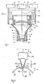
Fig. 1 is a cross sectional view of an embodiment of the device for calibrating a laser system of the present invention; -
Fig. 2 is a schematic view, not to scale, of the focal point of the laser beam of the system ofFig. 1 being directed into contact with the surface of the calibration member ofFig. 1 in accordance with the present invention; -
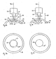
Figs. 3A, 4A ,5A and 6A are schematic elevation views, not to scale, of the system ofFig. 1 wherein the focal points of the respective laser beams are directed into contact with the calibration member while being directed in a circular path in accordance with the present invention; -
Figs. 3B, 4B ,5B, and 6B are respective plan views of the calibration member that correspond to laser beam directions indicated inFigs. 3A, 4A ,5A, and 6A ; and -
Figs. 7A and 7B are plan views of respective calibration members to which various laser beam focal point patterns have been applied in accordance with the present invention. - Referring initially to
Fig. 1 , a system for calibrating a, preferably femtosecond, laser system in accordance with the present invention is shown and generally designated 10. As shown, thesystem 10 includes alaser unit 12 for generating thelaser beam 14. Further, thelaser unit 12 defines abase datum 16 that will be used as a spatial reference for the calibration procedures performed by thesystem 10. As will be explained below, thesystem 10 relies on acalibration member 18 to calibrate thelaser unit 12. However, in order to properly explain thesystem 10, the general components used to focus thelaser beam 14 are first identified and discussed. - Structurally, the
laser unit 12 is mounted on ahousing 20. Thelaser unit 12 can be of any type well known in the art which is capable of generating anophthalmic laser beam 14. Furthermore, while a specific optical arrangement that can be used to direct thelaser beam 14 throughsystem 10 is shown, it is to be appreciated that any known optical arrangement can be employed. As shown inFig. 1 , thehousing 20 is fixedly attached to amechanism 22 for focusing thelaser beam 14. Specifically, thehousing 20 is connected to a substantiallycylindrical base 24 of themechanism 22. Further, themechanism 22 includes a substantiallycylindrical frame 26 to which thebase 24 is connected. - Still referring to
Fig. 1 , thesystem 10 is shown to have anobjective lens 28 for focusing thelaser beam 14. Structurally, thelens 28 is held in abracket 30 which has projections (not shown). Further, thebase 24 includes tracks 32 that receive and mate with the projections. As a result of this cooperation of structure, thelens 28 may be moved toward or away from thelaser unit 12 to focus thelaser beam 14 along a prescribed path for completion of the desired calibrating procedure. Alternatively, thelens 28 may be fixed and the focal point can be moved by changing the divergence of thelaser beam 14. It is, of course, within the scope of the present invention to use any other type of mechanism which allows control of the focus of thelaser beam 14 relative to thebase datum 16. It is further to be appreciated that a specific configuration C of the mechanism corresponds to a specific position of the focal spot. - As shown, the
frame 26 is fixed to a substantiallycylindrical alignment device 34. Further, during a calibration procedure thealignment device 34 is held against the substantially cylindrical calibration body 36. As shown inFig. 1 , the calibration body 36 preferably includes anupper part 37 and alower part 39 that can be selectively engaged, or disengaged from each other. Thus, thecalibration member 18 can be held between theupper part 37 and thelower part 39 when they are engaged. As envisioned for the present invention, theparts parts calibration member 18 removed for further, more precise, evaluation. Anew calibration member 18 can then be incorporated with the calibration body 36 and used for the test and evaluation of another, subsequent calibration procedure. More specifically, the subsequent evaluation can be accomplished using an external microscope with better resolution than could be obtained using only a surgical microscope that may be included as part of thelaser unit 12. As also shown inFig. 1 , thealignment device 34 is provided with achannel 38. Thechannel 38 is positioned adjacent theinterface 40 between theupper part 37 ofalignment device 34 and the calibration body 36. Thechannel 38 can be connected to a vacuum pump (not shown) to create a partial vacuum in thechannel 38 to hold thealignment device 34 against the calibration body 36 during a calibration procedure. - Still referring to
Fig. 1 , it can be seen that the cylindrical calibration body 36 has aninternal face 42 defining a hole 44 for passage of thelaser beam 14. Spanning the hole 44 is thecalibration member 18, which is made of a material having a predetermined arid well defined energy threshold for LIOB. The calibration body 36 andmember 18 may be unitary or separate components as disclosed above. As shown, thecalibration member 18 includes asurface 46 defining acentral axis 48 that passes through the apex of thesurface 46 and is substantially perpendicular thereto. In one aspect of the present invention, thesurface 46 is opposite thelaser unit 12 from thecalibration member 18. Stated differently, thecalibration member 18 is between thelaser unit 12 and thesurface 46. It is to be appreciated, however, that thesurface 46 can also face thelaser unit 12. In this case, thesurface 46 is between thecalibration member 18 and thelaser unit 12. In both instances, while thesurface 46 is shown to be curved, it may, alternatively, be flat. Typically, thesurface 46 has a similar shape to the patient interface (cornea) used during surgery. In certain embodiments, thesurface 46 has a predetermined curvature with a radius of curvature in a range between about eight and twelve millimeters. When assembled, thesurface 46 is positioned at a predetermined distance from thebase datum 16 of thelaser unit 12. As a result, thesystem 10 provides for precise calibration of thelaser beam 14 relative to thesurface 46 of thecalibration member 18. - As further shown, the
system 10 is provided with animaging device 50, such as a Charge-Coupled Device (CCD) camera or a surgical microscope and camera assembly, for identifying whether LIOB has occurred in thecalibration member 18. Specifically, theimaging device 50 is shown mounted to thehousing 20 adjacent thelaser unit 12. Additionally, ameasurement device 52 may be mounted to thehousing 20 to measure the position of the focal point of thelaser beam 14 relative to the base datum 16 (distance) and the central axis 48 (radial distance). - Referring now to
Fig. 2 , the use of thecalibration member 18 to calibrate the z-axis control of thelaser beam 14 will be explained. As shown, thelaser beam 14 is directed by the focusingmechanism 22 to afocal point 54 at a pre-selectedinitial location 56. In this initial stage, although the beam energy density atfocal point 54 is sufficient to cause LIOB of the material in thecalibration member 18, the maximum beam energy density reached in the beam 14' upstream of thefocal point 54 is insufficient to cause LIOB in thecalibration member 18. Thereafter, thefocal point 54 is moved in the direction ofarrow 58 coincident with or parallel to thecentral axis 48 in µm steps from beam 14' to 14" to 14"'. At the end of the movement of thefocal point 54 toward thecalibration member 18, thefocal point 54 ofbeam 14"' reaches thesurface 46 of thecalibration member 18 and LIOB occurs at thisfinal location 60. For the present invention, an imaging device 50 (shown inFig. 1 ) identifies the plasma spark associated with the occurrence of LIOB in thecalibration member 18. Alternatively, the occurrence of LIOB may be identified by an operator. For the circumstance wherein thefocal point 54 is at an initial location 56' that is above, instead of below, thecalibration member 18, a reverse movement of thefocal point 54 away from the focusingmechanism 22 and toward thecalibration member 18 is required. The consequence is essentially the same. - Upon identification of LIOB, movement of the
focal point 54 in the direction ofarrow 58 is ceased. Thereafter, the z-position of thefinal location 60 relative to thebase datum 16 may be measured by the measurement device 52 (shown inFig. 1 ) or derived from the configuration C of the focusingmechanism 22, and the z-axis control of thelaser system 10 can be calibrated. - Referring now to
Figs. 3A and 3B , the ability to calibrate tilt and decentration of abeam 14 from a laser unit 12 (shown inFig. 1 ) is illustrated. As shown, thefocal point 54 of thebeam 14 is moved oncircular paths 62 within the periphery of thesurface 46. As described above, thefocal point 54 is first positioned at aninitial location 56 downstream of thesurface 46 and then is moved in the direction ofarrow 58 toward thesurface 46 preferably in two micron steps. Thefocal point 54 moves from circular path 62' throughpath 62" to path 62'" where it contacts thesurface 46 of thecalibration member 18 at alocation 64. For the present invention, while continuing alongcircular paths 62, thefocal point 54 is moved upward until afull path 62"' is completed within thecalibration member 18. Then, the plurality oflocations 64 is used to calibrate a "tilt" and a "decenter" for thelaser beam 14. Specifically, the imaging device 50 (shown inFig. 1 ) records both the z-axis position of the first contact between thefocal point 54 and thesurface 46 as well as the z-axis position of the first circular path 62'" completely within thecalibration member 18. Because thelaser beam 14 shown inFig. 3A is in perfect alignment with thecalibration surface 46, LIOB will occur substantially simultaneously upon first contact between thefocal point 54 and thesurface 46 around thecircular path 62"'. While only fourlocations 64 are shown inFigs. 3A and 3B for purposes of clarity, it should be understood that LIOB occurs along the entire circular path 62'" in this example. - A determination as to whether the
circular path 62"' actually results from a perfect alignment of thelaser beam 14 can be easily verified. Specifically, this can be done after completion of the procedure disclosed immediately above. By rotating the calibration body 36 through a predetermined angle about the central axis 48 (e.g. 90° or 180°), a verification path 65 (shown as a dashed circle inFig. 3B ) can be made into thecalibration member 18. When theverification path 65 is congruent with thecircular path 62"', a perfect alignment of thelaser beam 14 with thecalibration member 18 is indicated. On the other hand, if theverification path 65 is displaced relative to thecircular path 62"' (as shown inFig. 3B ), further evaluation of tilt and decentration is required. - Referring now to
Figs. 4A and 4B , a calibration process is illustrated for abeam 14 that is laterally displaced to the left. As a result of this decentration, thefirst location 64 of LIOB, due to contact between thefocal point 54 and thesurface 46, is shifted to the left from the example seen inFigs. 3A and 3B . The radial distance betweenlocation 64 and thecentral axis 48 is represented by "r". Further, LIOB only occurs at thelocation 64 in the path 62'" as shown inFig. 4B . As can be understood, there would be a significant difference in the z-axis position of thelocation 64 and the first circular path (not shown) completely within thecalibration member 18 for abeam 14 with decentration. This z-axis difference can be measured and used to calibrate thebeam 14 based on the known curvature of thecalibration surface 46. - Referring now to
Figs. 5A and 5B , a calibration process is illustrated for abeam 14 experiencing tilt. As inFig. 4A , LIOB is shown first,occurring on the left side atlocation 64 which is spaced from thecentral axis 48 by a radial distance "r". The firstcircular path 62 to be completely within thecalibration member 18 will be centered about theoptical axis 66 which forms an angle with thecentral axis 48. As both theinitial location 64 of LIOB and the firstcircular path 62 fully within themember 18 are recorded by theimaging device 50 and measured by the measurement device 52 (both shown inFig. 1 ), thebeam 14 may be calibrated to correct the tilt. - Referring now to
Figs. 6A and 6B , a calibration process is illustrated for abeam 14 having anelliptical path 62"", such as might be caused by a mismatch of the galvanometric scanners (not shown) of the focusingmechanism 22. In this case, LIOB first occurs only atlocations 64 along the long axis of theelliptical path 62"". Further, thefirst path 62 fully within thecalibration member 18 will be elliptical. Again, theimaging device 50 and measurement device 52 (both shown inFig. 1 ) will identify and measure thelocations 64 and thefirst path 62 fully within themember 18 to calibrate thelaser beam 14. For the present invention, if the curvature of thesurface 46 is comparable to the curvature of a typical cornea, i.e., around 8-12 mm radius of curvature, and ifpaths 62 with a radius of about 5 mm are cut, then a lateral displacement of thebeam 14 will have approximately the same effect on z-axis displacement, i.e., a lateral displacement of 10 µm will result in a z-axis displacement of about 10 µm. As a result, if thepath 62 of thebeam 14 is moved in thedirection 58 in 2 micron steps, LIOB would occur along the long axis five steps before LIOB occurs along theentire path 62. Therefore, the elliptical nature of thepath 62 would be easily identified. On the other hand, due to the typically limited resolution and/or magnification of a standard surgical microscope installed inlaser systems 10, it would not be possible to detect a 10 micron difference between the two axes of an ellipse by measuring the ellipse. - As is understood from
Figs. 2-6B , the z-axis position, tilt/decenter, and any ellipticity oflaser beam 14 may be determined and calibrated using thesystem 10. Once the calibration is performed, thelaser beam 14 may be used to apply test patterns comprising a plurality offinal locations 60 within thecalibration member 18. Specifically, the test patterns may be applied via LIOB to check the energy density in the focal spot as well as the uniformity of the energy density over the treatment area. As shown inFigs. 7A and 7B , the energy density within thefocal point 54 can be determined by directing thefocal point 54 through thecalibration member 18 along a path defined by anenergy band 68,spokes 70, or circles 72 with increasing energy levels. Preferably each test pattern is respectively created using a different energy in thelaser beam 14 in a range between a low energy and a high energy, yielding an energy density at the focal point below the energy density threshold for LIOB of the calibration member, and a high energy density at the focal point above the energy density threshold for LIOB of the calibration member, to determine an energy density within the focal spot of thelaser beam 14. Typically, LIOB will occur at a certain energy level, i.e., at a certain position in theenergy band 68, at acertain spoke 70, or at acertain circle 72. As discussed above, the occurrence of LIOB can be detected by the operator or by the imaging device 50 (shown inFig. 1 ). - Further, a plurality of test patterns may be compared with each other to determine the uniformity of the energy density in the focal spot of the
laser beam 14. For instance, the uniformity of the energy density can be determined by looking atcircles 72 with different energy levels. If no fluctuations in the energy density in the focal spot of thebeam 14 are present, then eachcircle 72 will have an even intensity. Intensities will vary only betweencircles 72 formed with different beam energies. If there are fluctuations, then parts of thecircles 72 will appear fainter or may disappear. Preferably, the test patterns are created within the material of thecalibration member 18. With this in mind, the thickness of thecalibration member 18, between its upper and lower surfaces, will typically be about 0.5 millimeters. - As shown in
Fig. 7B , thebeam 14 can be used to applysystem information 74 to thecalibration member 18 for archiving purposes. As further seen inFigs. 7A and 7B , circles 76 having different depths, a cross-hair/scale 78, andreference circles 80 having predetermined diameters may be applied to thecalibration member 18. - While the particular Device and Method for Calibrating a Laser System as herein shown and disclosed in detail is fully capable of obtaining the objects and providing'the advantages herein before stated, it is to be understood that it is merely illustrative of the presently preferred embodiments of the invention and that no limitations are intended to the details of construction or design herein shown other than as described in the appended claims.
Claims (10)
- A calibratable surgical laser system (10) adapted for calibration of the position of a focal point (54) of the laser system (10), which comprises:a laser unit (12) for generating a laser beam (14), wherein said laser unit (12) defines a base datum (16);a calibration body (36) mounted on said laser unit (12);a calibration member (18) affixed to said calibration body and having a curved surface (46) with a predetermined curvature, wherein the surface (46) defines a central axis (48) substantially perpendicular thereto, and wherein said calibration member (18) is affixed to said calibration body (36) to position the surface (46) of said calibration member (18) at a predetermined distance from the base datum (16) of said laser unit (12);an optical means (22) for focusing the laser beam (14) to a focal point (54) at a pre-selected initial location (56) at a distance from the surface (46) of the calibration member (18);a means for moving the focal point toward the surface (46) of said calibration member (18) through a distance "d", until a Laser induced Optical Breakdown (LIOB) is induced at a final location (60) on the surface (46) of said calibration member (18);a means for determining the distance "d"; anda means for comparing the distance "d" with a predetermined value to calibrate the laser system (10).
- A system (10) as recited in claim 1 further comprising a means for measuring a radial distance "r" of the final location (60) from the central axis (48) to calibrate the laser system (10).
- A system (10) as recited in claim 1 , wherein the surface (46) has a radius of curvature in a range between about eight and twelve millimeters.
- A system (10) as recited in claim 1 wherein said calibration member (18) is made of a material having a predetermined energy threshold for LIOB.
- A system (10) as recited in claim 1 wherein a plurality of final locations (60) is used to calibrate a "tilt" and a "decenter" for the laser system (10), wherein preferably a plurality of final locations (60) creates a test pattern.
- A system (10) as recited in claim 5 wherein each test pattern is respectively created using a different energy in the laser beam (14), and wherein the respective different energies are in a range between a low energy and a high energy, yielding an energy density at the focal point (54) below the energy density threshold for LIOB of the calibration member (18), and a high energy density at the focal point (54) above the energy density threshold for LIOB of said calibration member (18) to determine an energy density for the focal spot of the laser beam (14), wherein preferably a plurality of test patterns are compared with each other to determine a uniformity for energy density in the focal spot of the laser beam (14).
- A method for calibrating the position of a focal point (54) of a surgical laser system (10), which comprises the steps of:supplying a means (12) for generating a laser beam (14)
wherein said generating means (12) defines a base datum (16);mounting a means (36) for calibrating the laser beam (14) to the generating means (12), with said calibrating means (36) including a curved calibration member surface (46) with a predetermined curvature, wherein the surface (46) defines a central axis (48) substantially perpendicular thereto, and wherein the surface (46) is positioned at a predetermined distance from the base datum (16) of said generating means (12);generating the laser beam (14) with the generating means (12) to pass the laser beam (14) through said calibration member surface (46);focusing the laser beam (14) to a focal point (54) at a preselected initial location (56) at a distance from the calibration member surface (46);moving the focal point through a distance "d", until a Laser Induced Optical Breakdown (LIOB) is induced at a final location (60) on the surface (46) of said calibration member (18);determining the distance "d"; andcomparing the distance "d" with a predetermined value to calibrate the laser system (10). - A method as recited in claim 7 further comprising the step of measuring a radial distance "r" of the final location (60) from the central axis (48) to calibrate the laser system (10).
- A method as recited in claim 7 further comprising the steps of:directing the focal point (54) away from the surface (46); andrepeating the moving and directing steps to induce LIOB at a plurality of final locations (60) on the surface (46) in order to calibrate a "tilt" and a "decenter" for the laser beam (14).
- A method as recited in claim 9 wherein the plurality of final locations (60) creates a test pattern, and wherein the moving and directing steps are performed multiple times to create a plurality of test patterns, with each test pattern respectively created using a different energy in the laser beam (14), and wherein the respective different energies are in a range between a low energy and a high energy, yielding an energy density at the focal point (54) below the energy density threshold for LIOB of the calibration member (18), and a high energy density at the focal point (54) above the energy density threshold for LIOB of said calibration member (18) to determine an energy density for the focal spot of the laser beam (14), preferably further comprising the step of comparing the plurality of test patterns with each other to determine a uniformity for energy density in the focal spot of the laser beam (14).
Applications Claiming Priority (2)
| Application Number | Priority Date | Filing Date | Title |
|---|---|---|---|
| US11/339,309 US20070173796A1 (en) | 2006-01-25 | 2006-01-25 | Device and method for calibrating a laser system |
| PCT/IB2006/003057 WO2007085891A1 (en) | 2006-01-25 | 2006-10-30 | Device and method for calibrating a laser system |
Publications (2)
| Publication Number | Publication Date |
|---|---|
| EP1976469A1 EP1976469A1 (en) | 2008-10-08 |
| EP1976469B1 true EP1976469B1 (en) | 2010-06-02 |
Family
ID=37714399
Family Applications (1)
| Application Number | Title | Priority Date | Filing Date |
|---|---|---|---|
| EP06809150A Active EP1976469B1 (en) | 2006-01-25 | 2006-10-30 | Device and method for calibrating a laser system |
Country Status (7)
| Country | Link |
|---|---|
| US (1) | US20070173796A1 (en) |
| EP (1) | EP1976469B1 (en) |
| JP (1) | JP5143746B2 (en) |
| AT (1) | ATE469622T1 (en) |
| DE (1) | DE602006014733D1 (en) |
| ES (1) | ES2346351T3 (en) |
| WO (1) | WO2007085891A1 (en) |
Families Citing this family (16)
| Publication number | Priority date | Publication date | Assignee | Title |
|---|---|---|---|---|
| WO2009033111A2 (en) | 2007-09-06 | 2009-03-12 | Lensx Lasers, Inc. | Precise targeting of surgical photodisruption |
| US8262647B2 (en) * | 2009-07-29 | 2012-09-11 | Alcon Lensx, Inc. | Optical system for ophthalmic surgical laser |
| US8419721B2 (en) * | 2009-07-29 | 2013-04-16 | Alcon Lensx, Inc. | Optical system for ophthalmic surgical laser |
| US9504608B2 (en) | 2009-07-29 | 2016-11-29 | Alcon Lensx, Inc. | Optical system with movable lens for ophthalmic surgical laser |
| US8267925B2 (en) * | 2009-07-29 | 2012-09-18 | Alcon Lensx, Inc. | Optical system for ophthalmic surgical laser |
| US8506559B2 (en) * | 2009-11-16 | 2013-08-13 | Alcon Lensx, Inc. | Variable stage optical system for ophthalmic surgical laser |
| FR2954199B1 (en) * | 2009-12-22 | 2013-07-26 | Commissariat Energie Atomique | METHOD FOR ABLATION OF A THREE-DIMENSIONAL SURFACE USING A LASER ABLATION DEVICE, AND DEVICE FOR CARRYING OUT THE METHOD |
| CA2812819C (en) * | 2010-09-30 | 2015-11-17 | Alcon Inc. | Process for testing a laser device |
| US10736781B2 (en) * | 2012-01-18 | 2020-08-11 | Alcon Inc. | Adjusting laser energy in accordance with optical density |
| US10182943B2 (en) | 2012-03-09 | 2019-01-22 | Alcon Lensx, Inc. | Adjustable pupil system for surgical laser systems |
| US8852177B2 (en) | 2012-03-09 | 2014-10-07 | Alcon Lensx, Inc. | Spatio-temporal beam modulator for surgical laser systems |
| WO2016026663A1 (en) * | 2014-08-20 | 2016-02-25 | Arcam Ab | Energy beam deflection speed verification |
| US9341467B2 (en) * | 2014-08-20 | 2016-05-17 | Arcam Ab | Energy beam position verification |
| WO2016026664A1 (en) * | 2014-08-20 | 2016-02-25 | Arcam Ab | Energy beam size verification |
| CA3002763A1 (en) | 2015-10-21 | 2017-04-27 | Optimedica Corporation | Laser beam calibration and beam quality measurement in laser surgery systems |
| US12594189B2 (en) * | 2022-09-02 | 2026-04-07 | Alcon Inc. | Long-term monitoring of the incision performance of an ophthalmic laser surgical system |
Family Cites Families (38)
| Publication number | Priority date | Publication date | Assignee | Title |
|---|---|---|---|---|
| US4287410A (en) * | 1979-02-28 | 1981-09-01 | Sri International | Double Purkinje eye tracker |
| US4702575A (en) * | 1981-05-11 | 1987-10-27 | The United States Of America As Represented By The Secretary Of The Navy | Helmet mounted eye tracker using a position sensing detector |
| US4443075A (en) * | 1981-06-26 | 1984-04-17 | Sri International | Stabilized visual system |
| FR2513873B1 (en) * | 1981-10-02 | 1985-10-25 | Essilor Int | OPHTHALMOLOGICAL LASER SURGERY APPARATUS |
| DE3427611A1 (en) * | 1984-07-26 | 1988-06-09 | Bille Josef | LASER BEAM LITHOGRAPH |
| US4772115A (en) * | 1986-09-02 | 1988-09-20 | Computed Anatomy Incorporated | Illuminated ring keratometer device |
| US4848340A (en) * | 1988-02-10 | 1989-07-18 | Intelligent Surgical Lasers | Eyetracker and method of use |
| US5865832A (en) * | 1992-02-27 | 1999-02-02 | Visx, Incorporated | System for detecting, measuring and compensating for lateral movements of a target |
| US6099522A (en) * | 1989-02-06 | 2000-08-08 | Visx Inc. | Automated laser workstation for high precision surgical and industrial interventions |
| US5062702A (en) * | 1990-03-16 | 1991-11-05 | Intelligent Surgical Lasers, Inc. | Device for mapping corneal topography |
| JPH07119144B2 (en) * | 1991-05-17 | 1995-12-20 | 富士ゼロックス株式会社 | Laser beam printer |
| US6325792B1 (en) * | 1991-11-06 | 2001-12-04 | Casimir A. Swinger | Ophthalmic surgical laser and method |
| US5303709A (en) * | 1991-12-16 | 1994-04-19 | Dreher Andreas W | Retinal eye disease diagnostic system |
| DE4232915A1 (en) * | 1992-10-01 | 1994-04-07 | Hohla Kristian | Device for shaping the cornea by removing tissue |
| US5336215A (en) * | 1993-01-22 | 1994-08-09 | Intelligent Surgical Lasers | Eye stabilizing mechanism for use in ophthalmic laser surgery |
| US5360424A (en) * | 1993-06-04 | 1994-11-01 | Summit Technology, Inc. | Tracking system for laser surgery |
| US5624437A (en) * | 1995-03-28 | 1997-04-29 | Freeman; Jerre M. | High resolution, high speed, programmable laser beam modulating apparatus for microsurgery |
| CN1198221A (en) * | 1995-09-29 | 1998-11-04 | 伯利乌·巴哈马有限公司 | Contact lens and process for fitting |
| AUPO810997A0 (en) * | 1997-07-18 | 1997-08-14 | Lions Eye Institute Of Western Australia Incorporated, The | Method and apparatus for calibration of ablation lasers |
| US5966197A (en) * | 1998-04-21 | 1999-10-12 | Visx, Incorporated | Linear array eye tracker |
| US6333485B1 (en) * | 1998-12-11 | 2001-12-25 | International Business Machines Corporation | Method for minimizing sample damage during the ablation of material using a focused ultrashort pulsed beam |
| DE19857694C2 (en) * | 1998-12-14 | 2001-07-19 | Precitec Gmbh | Method and device for adjusting the focus position of a laser beam directed at a workpiece |
| JP3246729B2 (en) * | 1999-02-25 | 2002-01-15 | 本田技研工業株式会社 | Laser welded body |
| US6373571B1 (en) * | 1999-03-11 | 2002-04-16 | Intralase Corp. | Disposable contact lens for use with an ophthalmic laser system |
| JP4251742B2 (en) * | 2000-01-14 | 2009-04-08 | 日立ビアメカニクス株式会社 | Laser processing equipment |
| JP3528746B2 (en) * | 2000-03-07 | 2004-05-24 | 株式会社デンソー | Welding method and manufacturing method of combination member and manufacturing method of valve structure |
| US6648877B1 (en) * | 2000-06-30 | 2003-11-18 | Intralase Corp. | Method for custom corneal corrections |
| JP4021136B2 (en) * | 2000-08-31 | 2007-12-12 | 株式会社ニデック | Cornea surgery device |
| US6607527B1 (en) * | 2000-10-17 | 2003-08-19 | Luis Antonio Ruiz | Method and apparatus for precision laser surgery |
| US6451006B1 (en) * | 2001-02-14 | 2002-09-17 | 20/10 Perfect Vision Optische Geraete Gmbh | Method for separating lamellae |
| US6579282B2 (en) * | 2001-04-25 | 2003-06-17 | 20/10 Perfect Vision Optische Geraete Gmbh | Device and method for creating a corneal reference for an eyetracker |
| US6730074B2 (en) * | 2002-05-24 | 2004-05-04 | 20/10 Perfect Vision Optische Geraete Gmbh | Cornea contact system for laser surgery |
| US6992765B2 (en) * | 2002-10-11 | 2006-01-31 | Intralase Corp. | Method and system for determining the alignment of a surface of a material in relation to a laser beam |
| JP4086667B2 (en) * | 2003-01-15 | 2008-05-14 | 株式会社ニデック | Cornea surgery device |
| US7131968B2 (en) * | 2003-06-02 | 2006-11-07 | Carl Zeiss Meditec Ag | Apparatus and method for opthalmologic surgical procedures using a femtosecond fiber laser |
| US7402159B2 (en) * | 2004-03-01 | 2008-07-22 | 20/10 Perfect Vision Optische Geraete Gmbh | System and method for positioning a patient for laser surgery |
| US7238176B2 (en) * | 2004-04-29 | 2007-07-03 | 20/10 Perfect Vision Optische Geraete Gmbh | Method for intrastromal photodisruption of dome-shaped surfaces |
| US7390089B2 (en) * | 2005-02-25 | 2008-06-24 | 20/10 Perfect Vision Optische Geraete Gmbh | Device and method for aligning an eye with a surgical laser |
-
2006
- 2006-01-25 US US11/339,309 patent/US20070173796A1/en not_active Abandoned
- 2006-10-30 JP JP2008551890A patent/JP5143746B2/en active Active
- 2006-10-30 WO PCT/IB2006/003057 patent/WO2007085891A1/en not_active Ceased
- 2006-10-30 ES ES06809150T patent/ES2346351T3/en active Active
- 2006-10-30 AT AT06809150T patent/ATE469622T1/en not_active IP Right Cessation
- 2006-10-30 EP EP06809150A patent/EP1976469B1/en active Active
- 2006-10-30 DE DE602006014733T patent/DE602006014733D1/en active Active
Also Published As
| Publication number | Publication date |
|---|---|
| JP5143746B2 (en) | 2013-02-13 |
| US20070173796A1 (en) | 2007-07-26 |
| ES2346351T3 (en) | 2010-10-14 |
| WO2007085891A1 (en) | 2007-08-02 |
| EP1976469A1 (en) | 2008-10-08 |
| ATE469622T1 (en) | 2010-06-15 |
| JP2009524525A (en) | 2009-07-02 |
| DE602006014733D1 (en) | 2010-07-15 |
Similar Documents
| Publication | Publication Date | Title |
|---|---|---|
| US20070173796A1 (en) | Device and method for calibrating a laser system | |
| CN101511523B (en) | Device and method for material processing using transparent contact elements | |
| US6992765B2 (en) | Method and system for determining the alignment of a surface of a material in relation to a laser beam | |
| EP3364924B1 (en) | Laser beam calibration and beam quality measurement in laser surgery systems | |
| US6373571B1 (en) | Disposable contact lens for use with an ophthalmic laser system | |
| US10772764B2 (en) | Laser treatment device | |
| CA2561388C (en) | Integrated surgical microscope and wavefront sensor | |
| EP1364632B1 (en) | Cornea contact system for laser surgery | |
| KR101629404B1 (en) | Device and method for processing material by means of focused electromagnetic radiation | |
| JP2015502765A (en) | Optical arrangement and method for detecting the orientation of an artificial lens | |
| CN103249517B (en) | For the method for testing laser equipment | |
| CN117062587A (en) | Method, control unit and laser processing system for performing system testing of a laser processing system | |
| JP2017176777A (en) | Ophthalmic laser surgery device and aberration correction method | |
| KR20260017194A (en) | Corneal shape measurement device |
Legal Events
| Date | Code | Title | Description |
|---|---|---|---|
| PUAI | Public reference made under article 153(3) epc to a published international application that has entered the european phase |
Free format text: ORIGINAL CODE: 0009012 |
|
| 17P | Request for examination filed |
Effective date: 20080617 |
|
| AK | Designated contracting states |
Kind code of ref document: A1 Designated state(s): AT BE BG CH CY CZ DE DK EE ES FI FR GB GR HU IE IS IT LI LT LU LV MC NL PL PT RO SE SI SK TR |
|
| RAP1 | Party data changed (applicant data changed or rights of an application transferred) |
Owner name: 20/10 PERFECT VISION AG |
|
| RIN1 | Information on inventor provided before grant (corrected) |
Inventor name: KUHN, TOBIAS Inventor name: WUEHL, STEFAN Inventor name: MARTIN, MARCEL Inventor name: VON PAPE, ULRICH Inventor name: KESSLER, RALF |
|
| RAP1 | Party data changed (applicant data changed or rights of an application transferred) |
Owner name: TECHNOLAS PERFECT VISION GMBH |
|
| 17Q | First examination report despatched |
Effective date: 20090716 |
|
| GRAP | Despatch of communication of intention to grant a patent |
Free format text: ORIGINAL CODE: EPIDOSNIGR1 |
|
| DAX | Request for extension of the european patent (deleted) | ||
| GRAS | Grant fee paid |
Free format text: ORIGINAL CODE: EPIDOSNIGR3 |
|
| GRAA | (expected) grant |
Free format text: ORIGINAL CODE: 0009210 |
|
| AK | Designated contracting states |
Kind code of ref document: B1 Designated state(s): AT BE BG CH CY CZ DE DK EE ES FI FR GB GR HU IE IS IT LI LT LU LV MC NL PL PT RO SE SI SK TR |
|
| REG | Reference to a national code |
Ref country code: GB Ref legal event code: FG4D |
|
| REG | Reference to a national code |
Ref country code: CH Ref legal event code: EP |
|
| REG | Reference to a national code |
Ref country code: IE Ref legal event code: FG4D |
|
| REF | Corresponds to: |
Ref document number: 602006014733 Country of ref document: DE Date of ref document: 20100715 Kind code of ref document: P |
|
| REG | Reference to a national code |
Ref country code: NL Ref legal event code: VDEP Effective date: 20100602 |
|
| REG | Reference to a national code |
Ref country code: ES Ref legal event code: FG2A Ref document number: 2346351 Country of ref document: ES Kind code of ref document: T3 |
|
| PG25 | Lapsed in a contracting state [announced via postgrant information from national office to epo] |
Ref country code: SE Free format text: LAPSE BECAUSE OF FAILURE TO SUBMIT A TRANSLATION OF THE DESCRIPTION OR TO PAY THE FEE WITHIN THE PRESCRIBED TIME-LIMIT Effective date: 20100602 Ref country code: LT Free format text: LAPSE BECAUSE OF FAILURE TO SUBMIT A TRANSLATION OF THE DESCRIPTION OR TO PAY THE FEE WITHIN THE PRESCRIBED TIME-LIMIT Effective date: 20100602 |
|
| LTIE | Lt: invalidation of european patent or patent extension |
Effective date: 20100602 |
|
| PG25 | Lapsed in a contracting state [announced via postgrant information from national office to epo] |
Ref country code: FI Free format text: LAPSE BECAUSE OF FAILURE TO SUBMIT A TRANSLATION OF THE DESCRIPTION OR TO PAY THE FEE WITHIN THE PRESCRIBED TIME-LIMIT Effective date: 20100602 Ref country code: LV Free format text: LAPSE BECAUSE OF FAILURE TO SUBMIT A TRANSLATION OF THE DESCRIPTION OR TO PAY THE FEE WITHIN THE PRESCRIBED TIME-LIMIT Effective date: 20100602 Ref country code: SI Free format text: LAPSE BECAUSE OF FAILURE TO SUBMIT A TRANSLATION OF THE DESCRIPTION OR TO PAY THE FEE WITHIN THE PRESCRIBED TIME-LIMIT Effective date: 20100602 Ref country code: AT Free format text: LAPSE BECAUSE OF FAILURE TO SUBMIT A TRANSLATION OF THE DESCRIPTION OR TO PAY THE FEE WITHIN THE PRESCRIBED TIME-LIMIT Effective date: 20100602 |
|
| PG25 | Lapsed in a contracting state [announced via postgrant information from national office to epo] |
Ref country code: CY Free format text: LAPSE BECAUSE OF FAILURE TO SUBMIT A TRANSLATION OF THE DESCRIPTION OR TO PAY THE FEE WITHIN THE PRESCRIBED TIME-LIMIT Effective date: 20100602 Ref country code: PL Free format text: LAPSE BECAUSE OF FAILURE TO SUBMIT A TRANSLATION OF THE DESCRIPTION OR TO PAY THE FEE WITHIN THE PRESCRIBED TIME-LIMIT Effective date: 20100602 Ref country code: GR Free format text: LAPSE BECAUSE OF FAILURE TO SUBMIT A TRANSLATION OF THE DESCRIPTION OR TO PAY THE FEE WITHIN THE PRESCRIBED TIME-LIMIT Effective date: 20100903 |
|
| PG25 | Lapsed in a contracting state [announced via postgrant information from national office to epo] |
Ref country code: NL Free format text: LAPSE BECAUSE OF FAILURE TO SUBMIT A TRANSLATION OF THE DESCRIPTION OR TO PAY THE FEE WITHIN THE PRESCRIBED TIME-LIMIT Effective date: 20100602 Ref country code: EE Free format text: LAPSE BECAUSE OF FAILURE TO SUBMIT A TRANSLATION OF THE DESCRIPTION OR TO PAY THE FEE WITHIN THE PRESCRIBED TIME-LIMIT Effective date: 20100602 |
|
| PG25 | Lapsed in a contracting state [announced via postgrant information from national office to epo] |
Ref country code: BE Free format text: LAPSE BECAUSE OF FAILURE TO SUBMIT A TRANSLATION OF THE DESCRIPTION OR TO PAY THE FEE WITHIN THE PRESCRIBED TIME-LIMIT Effective date: 20100602 Ref country code: IS Free format text: LAPSE BECAUSE OF FAILURE TO SUBMIT A TRANSLATION OF THE DESCRIPTION OR TO PAY THE FEE WITHIN THE PRESCRIBED TIME-LIMIT Effective date: 20101002 Ref country code: SK Free format text: LAPSE BECAUSE OF FAILURE TO SUBMIT A TRANSLATION OF THE DESCRIPTION OR TO PAY THE FEE WITHIN THE PRESCRIBED TIME-LIMIT Effective date: 20100602 Ref country code: CZ Free format text: LAPSE BECAUSE OF FAILURE TO SUBMIT A TRANSLATION OF THE DESCRIPTION OR TO PAY THE FEE WITHIN THE PRESCRIBED TIME-LIMIT Effective date: 20100602 Ref country code: PT Free format text: LAPSE BECAUSE OF FAILURE TO SUBMIT A TRANSLATION OF THE DESCRIPTION OR TO PAY THE FEE WITHIN THE PRESCRIBED TIME-LIMIT Effective date: 20101004 Ref country code: RO Free format text: LAPSE BECAUSE OF FAILURE TO SUBMIT A TRANSLATION OF THE DESCRIPTION OR TO PAY THE FEE WITHIN THE PRESCRIBED TIME-LIMIT Effective date: 20100602 |
|
| PLBE | No opposition filed within time limit |
Free format text: ORIGINAL CODE: 0009261 |
|
| STAA | Information on the status of an ep patent application or granted ep patent |
Free format text: STATUS: NO OPPOSITION FILED WITHIN TIME LIMIT |
|
| PG25 | Lapsed in a contracting state [announced via postgrant information from national office to epo] |
Ref country code: DK Free format text: LAPSE BECAUSE OF FAILURE TO SUBMIT A TRANSLATION OF THE DESCRIPTION OR TO PAY THE FEE WITHIN THE PRESCRIBED TIME-LIMIT Effective date: 20100602 |
|
| 26N | No opposition filed |
Effective date: 20110303 |
|
| PG25 | Lapsed in a contracting state [announced via postgrant information from national office to epo] |
Ref country code: MC Free format text: LAPSE BECAUSE OF NON-PAYMENT OF DUE FEES Effective date: 20101031 |
|
| REG | Reference to a national code |
Ref country code: CH Ref legal event code: PL |
|
| REG | Reference to a national code |
Ref country code: DE Ref legal event code: R097 Ref document number: 602006014733 Country of ref document: DE Effective date: 20110302 |
|
| PG25 | Lapsed in a contracting state [announced via postgrant information from national office to epo] |
Ref country code: CH Free format text: LAPSE BECAUSE OF NON-PAYMENT OF DUE FEES Effective date: 20101031 Ref country code: LI Free format text: LAPSE BECAUSE OF NON-PAYMENT OF DUE FEES Effective date: 20101031 |
|
| PG25 | Lapsed in a contracting state [announced via postgrant information from national office to epo] |
Ref country code: IE Free format text: LAPSE BECAUSE OF NON-PAYMENT OF DUE FEES Effective date: 20101030 |
|
| PG25 | Lapsed in a contracting state [announced via postgrant information from national office to epo] |
Ref country code: BG Free format text: LAPSE BECAUSE OF FAILURE TO SUBMIT A TRANSLATION OF THE DESCRIPTION OR TO PAY THE FEE WITHIN THE PRESCRIBED TIME-LIMIT Effective date: 20100602 Ref country code: LU Free format text: LAPSE BECAUSE OF NON-PAYMENT OF DUE FEES Effective date: 20101030 Ref country code: HU Free format text: LAPSE BECAUSE OF FAILURE TO SUBMIT A TRANSLATION OF THE DESCRIPTION OR TO PAY THE FEE WITHIN THE PRESCRIBED TIME-LIMIT Effective date: 20101203 |
|
| PG25 | Lapsed in a contracting state [announced via postgrant information from national office to epo] |
Ref country code: TR Free format text: LAPSE BECAUSE OF FAILURE TO SUBMIT A TRANSLATION OF THE DESCRIPTION OR TO PAY THE FEE WITHIN THE PRESCRIBED TIME-LIMIT Effective date: 20100602 |
|
| PG25 | Lapsed in a contracting state [announced via postgrant information from national office to epo] |
Ref country code: BG Free format text: LAPSE BECAUSE OF FAILURE TO SUBMIT A TRANSLATION OF THE DESCRIPTION OR TO PAY THE FEE WITHIN THE PRESCRIBED TIME-LIMIT Effective date: 20100902 |
|
| REG | Reference to a national code |
Ref country code: FR Ref legal event code: PLFP Year of fee payment: 11 |
|
| REG | Reference to a national code |
Ref country code: FR Ref legal event code: PLFP Year of fee payment: 12 |
|
| REG | Reference to a national code |
Ref country code: FR Ref legal event code: PLFP Year of fee payment: 13 |
|
| P01 | Opt-out of the competence of the unified patent court (upc) registered |
Effective date: 20230508 |
|
| PGFP | Annual fee paid to national office [announced via postgrant information from national office to epo] |
Ref country code: IT Payment date: 20250923 Year of fee payment: 20 |
|
| PGFP | Annual fee paid to national office [announced via postgrant information from national office to epo] |
Ref country code: GB Payment date: 20250923 Year of fee payment: 20 |
|
| PGFP | Annual fee paid to national office [announced via postgrant information from national office to epo] |
Ref country code: FR Payment date: 20250924 Year of fee payment: 20 |
|
| PGFP | Annual fee paid to national office [announced via postgrant information from national office to epo] |
Ref country code: DE Payment date: 20250923 Year of fee payment: 20 |
|
| PGFP | Annual fee paid to national office [announced via postgrant information from national office to epo] |
Ref country code: ES Payment date: 20251103 Year of fee payment: 20 |