EP1169985A2 - Method for preparing apparatus for custom corneal corrections - Google Patents
Method for preparing apparatus for custom corneal corrections Download PDFInfo
- Publication number
- EP1169985A2 EP1169985A2 EP01301727A EP01301727A EP1169985A2 EP 1169985 A2 EP1169985 A2 EP 1169985A2 EP 01301727 A EP01301727 A EP 01301727A EP 01301727 A EP01301727 A EP 01301727A EP 1169985 A2 EP1169985 A2 EP 1169985A2
- Authority
- EP
- European Patent Office
- Prior art keywords
- laser beam
- cornea
- incising
- recited
- focal spot
- Prior art date
- Legal status (The legal status is an assumption and is not a legal conclusion. Google has not performed a legal analysis and makes no representation as to the accuracy of the status listed.)
- Granted
Links
- 238000000034 method Methods 0.000 title claims abstract description 45
- 238000012937 correction Methods 0.000 title claims abstract description 25
- 210000004087 cornea Anatomy 0.000 claims abstract description 48
- 230000003287 optical effect Effects 0.000 claims description 28
- 230000004075 alteration Effects 0.000 claims description 22
- 230000003213 activating effect Effects 0.000 claims 1
- 230000001404 mediated effect Effects 0.000 description 5
- 238000001356 surgical procedure Methods 0.000 description 5
- 238000002679 ablation Methods 0.000 description 2
- 230000000295 complement effect Effects 0.000 description 2
- 239000012634 fragment Substances 0.000 description 2
- 210000003484 anatomy Anatomy 0.000 description 1
- 238000010276 construction Methods 0.000 description 1
- 230000001276 controlling effect Effects 0.000 description 1
- 230000002596 correlated effect Effects 0.000 description 1
- 230000000875 corresponding effect Effects 0.000 description 1
- 230000000694 effects Effects 0.000 description 1
- 238000005516 engineering process Methods 0.000 description 1
Images
Classifications
-
- A—HUMAN NECESSITIES
- A61—MEDICAL OR VETERINARY SCIENCE; HYGIENE
- A61F—FILTERS IMPLANTABLE INTO BLOOD VESSELS; PROSTHESES; DEVICES PROVIDING PATENCY TO, OR PREVENTING COLLAPSING OF, TUBULAR STRUCTURES OF THE BODY, e.g. STENTS; ORTHOPAEDIC, NURSING OR CONTRACEPTIVE DEVICES; FOMENTATION; TREATMENT OR PROTECTION OF EYES OR EARS; BANDAGES, DRESSINGS OR ABSORBENT PADS; FIRST-AID KITS
- A61F9/00—Methods or devices for treatment of the eyes; Devices for putting in contact-lenses; Devices to correct squinting; Apparatus to guide the blind; Protective devices for the eyes, carried on the body or in the hand
- A61F9/007—Methods or devices for eye surgery
- A61F9/008—Methods or devices for eye surgery using laser
-
- A—HUMAN NECESSITIES
- A61—MEDICAL OR VETERINARY SCIENCE; HYGIENE
- A61F—FILTERS IMPLANTABLE INTO BLOOD VESSELS; PROSTHESES; DEVICES PROVIDING PATENCY TO, OR PREVENTING COLLAPSING OF, TUBULAR STRUCTURES OF THE BODY, e.g. STENTS; ORTHOPAEDIC, NURSING OR CONTRACEPTIVE DEVICES; FOMENTATION; TREATMENT OR PROTECTION OF EYES OR EARS; BANDAGES, DRESSINGS OR ABSORBENT PADS; FIRST-AID KITS
- A61F9/00—Methods or devices for treatment of the eyes; Devices for putting in contact-lenses; Devices to correct squinting; Apparatus to guide the blind; Protective devices for the eyes, carried on the body or in the hand
- A61F9/007—Methods or devices for eye surgery
- A61F9/008—Methods or devices for eye surgery using laser
- A61F9/00825—Methods or devices for eye surgery using laser for photodisruption
- A61F9/00827—Refractive correction, e.g. lenticle
- A61F9/00829—Correction of higher orders
-
- A—HUMAN NECESSITIES
- A61—MEDICAL OR VETERINARY SCIENCE; HYGIENE
- A61F—FILTERS IMPLANTABLE INTO BLOOD VESSELS; PROSTHESES; DEVICES PROVIDING PATENCY TO, OR PREVENTING COLLAPSING OF, TUBULAR STRUCTURES OF THE BODY, e.g. STENTS; ORTHOPAEDIC, NURSING OR CONTRACEPTIVE DEVICES; FOMENTATION; TREATMENT OR PROTECTION OF EYES OR EARS; BANDAGES, DRESSINGS OR ABSORBENT PADS; FIRST-AID KITS
- A61F9/00—Methods or devices for treatment of the eyes; Devices for putting in contact-lenses; Devices to correct squinting; Apparatus to guide the blind; Protective devices for the eyes, carried on the body or in the hand
- A61F9/007—Methods or devices for eye surgery
- A61F9/008—Methods or devices for eye surgery using laser
- A61F2009/00861—Methods or devices for eye surgery using laser adapted for treatment at a particular location
- A61F2009/00872—Cornea
-
- A—HUMAN NECESSITIES
- A61—MEDICAL OR VETERINARY SCIENCE; HYGIENE
- A61F—FILTERS IMPLANTABLE INTO BLOOD VESSELS; PROSTHESES; DEVICES PROVIDING PATENCY TO, OR PREVENTING COLLAPSING OF, TUBULAR STRUCTURES OF THE BODY, e.g. STENTS; ORTHOPAEDIC, NURSING OR CONTRACEPTIVE DEVICES; FOMENTATION; TREATMENT OR PROTECTION OF EYES OR EARS; BANDAGES, DRESSINGS OR ABSORBENT PADS; FIRST-AID KITS
- A61F9/00—Methods or devices for treatment of the eyes; Devices for putting in contact-lenses; Devices to correct squinting; Apparatus to guide the blind; Protective devices for the eyes, carried on the body or in the hand
- A61F9/007—Methods or devices for eye surgery
- A61F9/008—Methods or devices for eye surgery using laser
- A61F2009/00878—Planning
- A61F2009/0088—Planning based on wavefront
-
- A—HUMAN NECESSITIES
- A61—MEDICAL OR VETERINARY SCIENCE; HYGIENE
- A61F—FILTERS IMPLANTABLE INTO BLOOD VESSELS; PROSTHESES; DEVICES PROVIDING PATENCY TO, OR PREVENTING COLLAPSING OF, TUBULAR STRUCTURES OF THE BODY, e.g. STENTS; ORTHOPAEDIC, NURSING OR CONTRACEPTIVE DEVICES; FOMENTATION; TREATMENT OR PROTECTION OF EYES OR EARS; BANDAGES, DRESSINGS OR ABSORBENT PADS; FIRST-AID KITS
- A61F9/00—Methods or devices for treatment of the eyes; Devices for putting in contact-lenses; Devices to correct squinting; Apparatus to guide the blind; Protective devices for the eyes, carried on the body or in the hand
- A61F9/007—Methods or devices for eye surgery
- A61F9/008—Methods or devices for eye surgery using laser
- A61F2009/00878—Planning
- A61F2009/00882—Planning based on topography
Definitions
- the present invention pertains generally to ophthalmic surgical procedures which use pulsed laser beams to photoalter tissue of the cornea. More particularly, the present invention pertains to methods for preparing laser beam apparatus for use in ophthalmic surgical procedures which effect the correction of optical aberrations identified by reference to diagnostically predetermined refractive power maps. Apparatus prepared by methods of the present invention are particularly, but not exclusively, useful for conducting an ophthalmic surgical procedure that is customized to correct the specific optical aberrations of a particular eye.
- Optical aberrations of an eye generally manifest themselves as asymmetric distortions relative to the optical axis of the eye. Further, they are typically non-spherical in their geometry. Consequently, in order to successfully accomplish high-accuracy corrections of these optical aberrations, it is necessary to have detailed and accurate information about the optical aberrations. It is also necessary to have a surgical instrument that is capable of precisely and accurately performing the necessary surgical procedures.
- Non-ultraviolet, ultrashort pulsed laser technology has now advanced to the point where pulsed laser beams can be produced that have pulses with durations measured in femptoseconds.
- U.S. Patent No. 5,993,438 which issued to Juhasz et al. for an invention entitled "Intrastromal Photorefractive Keratectomy" (hereinafter the Juhasz Patent).
- a device as disclosed in the Juhasz Patent is effective for performing ophthalmic surgical procedures with the precision that is required for high-accuracy corrections of optical aberrations.
- the present invention provides a method for preparing an apparatus for customizing corneal corrections which apparatus comprises an incising laser beam and wherein the method comprises the step of superposing a reference field on the anterior surface of the cornea of an eye to divide the corneal surface into a plurality of reference areas which are suitable for:
- the invention also provides a method for preparing and an apparatus for surgically correcting optical aberrations of an eye which apparatus comprises an incising laser beam and wherein the method comprises the step of establishing a plurality of reference volumes in the cornea of the eye, which reference volumes are suitable for:
- the invention also provides a system for customizing corneal corrections which comprises:
- a method for customizing corneal corrections using apparatus prepared by a method of the invention includes obtaining information about the optical aberrations of the particular eye that is to be corrected.
- this information will be in the form of a refractive power map, such as a corneal topograph.
- refractive power maps of this type can be generated using wavefront analysis techniques that will show the amount of correction required in each particular area of the cornea.
- a reference field is superposed on the anterior surface of the cornea of the eye.
- the purpose of this reference field (grid) is really two-fold.
- the reference field (grid) is used to divide the corneal surface into a plurality of individual reference areas that can be identified with corresponding portions of the refractive power map.
- the reference areas provide targets for control in aiming, or directing, an incising laser beam toward the stromal tissue that is to be photoaltered.
- the reference areas can be extended to define respective reference volumes.
- the reference area will be generally square and quite small, with sides on the order of about ten microns in length. The reference volume will then extend through the cornea between the anterior and posterior surfaces of the cornea.
- the incising laser beam is directed along a beam path and through a selected reference area to a focal spot.
- the stromal tissue at the focal spot is then photoaltered.
- lasers may be used for plasma mediated tissue ablation (generally superficial tissue) and for plasma mediated tissue disruption (generally internal bulk tissue).
- plasma mediated tissue ablation generally superficial tissue
- plasma mediated tissue disruption generally internal bulk tissue
- photoalteration is used in the context of the present invention to indicate an operation wherein there may be either plasma mediated tissue ablation or plasma mediated tissue disruption.
- the incising laser beam is a non-ultraviolet ultrashort-pulsed laser beam having a plurality of pulses that each have a duration greater than approximately ten femtoseconds.
- the incising laser beam While the incising laser beam is activated, its focal spot is selectively moved along the beam path to photoalter stromal tissue through a predetermined length of the beam path. The incising laser beam is then redirected through another reference area and the process of photoalteration is repeated.
- the sequence for directing the incising laser beam through individually selected reference areas, and the extent of stromal tissue photoalteration while the incising laser beam is so directed can be varied as required. Specifically, as indicated above, the amount of photoalteration will be determined by the refractive power map. On the other hand, the sequence of reference areas that is followed during a customized procedure will depend on the particular objectives of the procedure.
- the present invention envisions the use of an apparatus prepared by a method of the invention in a LASIK type procedure wherein a flap is cut into the cornea to establish extracorporeal access to the tissue that is to be photoaltered. Once access has been achieved, the photoalteration is accomplished and the residual fragments of the photoaltered tissue are mechanically removed from the cornea.
- the present invention envisions that the use of an apparatus prepared by a method of the invention in the photoalteration of intrastromal tissue will result in the creation of an isolated lenticle of intrastromal tissue. For this procedure, once the lenticle of tissue has been created it can be mechanically removed from the cornea.
- photoalteration of stromal tissue will be accomplished in accordance with the dictates of a refractive power map.
- the result is a customized reconfiguration of the cornea that will correct the specific optical aberrations of a particular eye.
- an ophthalmic laser apparatus prepared by a method of the present invention is shown and is generally designated 10.
- the device 10 includes a laser source 12 which is capable of generating a non-ultraviolet, ultrashort-pulsed incising laser beam 14.
- Focusing optics 16, which have components that are well-known in the pertinent art, are provided for directing and focusing the incising laser beam 14. As intended for the present invention, the focusing optics 16 will direct the incising laser beam 14 toward the eye 18.
- the focusing optics 16 will focus the incising laser beam 14 either onto the cornea 20 for plasma mediated (non-UV) photoablation of superficial tissue, or into the stroma of the cornea 20 for intrastromal photodisruption of tissue (i.e. photoalteration).
- Fig. 1 also shows that the device 10 includes a reference unit 22 that will be used to establish a reference field (i.e. imaginary grid) 24 on the anterior surface 26 of the cornea 20.
- a reference field i.e. imaginary grid
- the imaginary reference field (grid) 24 is electronically generated by the reference unit 22 to identify a plurality of reference areas 28 on the anterior surface 26. These reference areas 28 can then be used for purposes of controlling the direction of the incising laser beam 14 toward the cornea 20.
- the specific reference areas 28a, 28b, 28c and 28d are only exemplary.
- the grid lines that are illustrated in Fig. 1 to establish the various reference areas 28 are presented only for purposes of disclosing the relationship of the reference areas 28 to each other, and to the cornea 20. Stated differently, in practice, the reference areas 28 will be electrically identified in the reference unit 22, and will not necessarily be visible on the anterior surface 26 of the cornea 20.
- each reference volume 30 extends through the cornea 20 from the anterior surface 26 to the posterior surface 32.
- the actual size of each reference volume 30 will thus depend on the thickness of the cornea 20 and the lengths of the x-dimension 34 and ⁇ -dimension 36 of the respective reference area 28.
- the x-dimension 34 and the y-dimension 36 will preferably be around ten microns in length.
- Fig. 2 also shows that within a particular reference volume 30 a length 38 can be established which will define a tissue volume 40.
- the tissue volume 40 shown in Fig. 2 is located within a projection of the reference area 28a through the cornea 20, and is bounded between the end 42 and the end 44.
- the size of a tissue volume 40 will depend on the size of the respective reference area 28 and the extent of length 38.
- the extent of length 38 is diagnostically determined.
- Fig. 3 is a plan view of a representative refractive power map 46 that has been diagnostically determined for a cornea 20.
- a refractive power map 46 can be generated using optical techniques that are well known in the pertinent art, such as by wavefront analysis. Once generated, the refractive power map 46 effectively indicates those portions of the cornea 20 that contribute to the optical aberrations. For example, if the area 48 of the refractive power map 46 is considered equivalent to a normal eye 18, the area 50 will indicate a deviation from this norm that requires some optical correction. Specifically, the correction required for the deviation will be stated in diopters. Further, the area 52 will indicate a deviation from the norm where additional optical correction is required. With the areas 48, 50 and 52 properly identified, it is well known that the removal or alteration of precise amounts of stromal tissue from selected areas of the cornea 20 (e.g. areas 50 and 52), will result in the desired optical correction.
- the refractive power map 46 for the cornea 20 is created first.
- the map 46 is then analyzed to identify areas on the map 46 that correspond with the imaginary reference field (grid) 24 that is generated in the reference unit 22.
- the map 46 is correlated with reference areas 28 of the reference field (grid) 24 and the contribution each reference volume 30 makes to the optical aberrations of cornea 20 is determined.
- the size of the tissue volume 40 that is to be removed from the reference volume 30 is determined.
- the laser source 12 is activated, and the focusing optics 16 are also activated to direct an incising laser beam 14 along a beam path 54.
- the incising laser beam 14 can be directed toward a preselected reference area 28 on the anterior surface 26 of the cornea 20 (the beam paths 54a, 54b, 54c and 54d are only exemplary).
- the incising laser beam 14 can be directed along the beam path 54b for incidence on the reference area 28b.
- the incising laser beam 14, when so directed can then be focused onto the reference area 28b, or be passed through the reference area 28b and focused to a focal spot 56b in the reference volume 30b. In either case, the incising laser beam 14 is focused in a manner which will cause it to photoalter the tissue at the focal spot 56.
- the incising laser beam 14 can be selectively redirected to move from one focal spot 56 to another focal spot 56. Also, the incising laser beam 14 can be moved from a focal spot 56 in one reference volume 30 to a focal spot 56 in another reference volume 30. For example, the incising laser beam 14 can be focused to the focal spot 56b in reference volume 30b and, subsequently, focused to the focal spot 56b' in the reference volume 30b. Similarly, the incising laser beam 14 can be subsequently focused to the focal spot 56d in reference volume 30d. Thus, the focal spot 56 of the incising laser beam 14 can be moved, as desired, in the x-direction and in the y-direction.
- the focal spot can be moved along the length 38 in a predetermined tissue volume 40 (Z direction).
- predetermined volumes of stromal tissue such as a lenticle
- layers of stromal tissue can be photoaltered to create passageways through the stroma.
- whole volumes of tissue can be photoaltered, and the resultant debris removed.
- the removal of stromal tissue can be customized. Stated differently, the objective is to remove the stromal tissue, and only the stromal tissue, that will make whatever optical corrections are necessary.
Landscapes
- Health & Medical Sciences (AREA)
- Ophthalmology & Optometry (AREA)
- Heart & Thoracic Surgery (AREA)
- Vascular Medicine (AREA)
- Optics & Photonics (AREA)
- Surgery (AREA)
- Engineering & Computer Science (AREA)
- Biomedical Technology (AREA)
- Physics & Mathematics (AREA)
- Nuclear Medicine, Radiotherapy & Molecular Imaging (AREA)
- Life Sciences & Earth Sciences (AREA)
- Animal Behavior & Ethology (AREA)
- General Health & Medical Sciences (AREA)
- Public Health (AREA)
- Veterinary Medicine (AREA)
- Laser Surgery Devices (AREA)
- Radiation-Therapy Devices (AREA)
- Eye Examination Apparatus (AREA)
Abstract
Description
- The present invention pertains generally to ophthalmic surgical procedures which use pulsed laser beams to photoalter tissue of the cornea. More particularly, the present invention pertains to methods for preparing laser beam apparatus for use in ophthalmic surgical procedures which effect the correction of optical aberrations identified by reference to diagnostically predetermined refractive power maps. Apparatus prepared by methods of the present invention are particularly, but not exclusively, useful for conducting an ophthalmic surgical procedure that is customized to correct the specific optical aberrations of a particular eye.
- Optical aberrations of an eye generally manifest themselves as asymmetric distortions relative to the optical axis of the eye. Further, they are typically non-spherical in their geometry. Consequently, in order to successfully accomplish high-accuracy corrections of these optical aberrations, it is necessary to have detailed and accurate information about the optical aberrations. It is also necessary to have a surgical instrument that is capable of precisely and accurately performing the necessary surgical procedures.
- Non-ultraviolet, ultrashort pulsed laser technology has now advanced to the point where pulsed laser beams can be produced that have pulses with durations measured in femptoseconds. For example, see U.S. Patent No. 5,993,438 which issued to Juhasz et al. for an invention entitled "Intrastromal Photorefractive Keratectomy" (hereinafter the Juhasz Patent). Importantly, it is known that a device as disclosed in the Juhasz Patent is effective for performing ophthalmic surgical procedures with the precision that is required for high-accuracy corrections of optical aberrations.
- As indicated above, in addition to having an effective surgical laser, it is also important to have detailed information about the optical aberrations that are to be corrected. Specifically, it is necessary to know the extent of the desired correction, and the location in the cornea of the eye where the correction can be made most effectively. For these purposes, it is necessary to precisely determine the refractive power of the cornea. It happens that wavefront analysis techniques, made possible by devices such as the well-known Hartmann-Shack type sensor, can be used to generate maps of corneal refractive power. These maps, or similar refractive power information provided by other means such as corneal topographs, can then be used by the ophthalmic surgeon to identify and locate the optical aberrations of a cornea that require correction.
- In light of the above, it is an object of the present invention to provide a device, and a method for preparing the device so that it is suitable for use in corneal corrections by effectively using a refractive power map as a tool for guiding an incising laser beam. It is another object of the present invention to provide a device, and a method for preparing the device so that it is suitable for use in the photoalteration of corneal tissue, which photoalteration is confined to only the volume of tissue that is required to achieve the desired optical corrections for the cornea. Still another object of the present invention is to provide a device, and a method for preparing the device, that is easy to implement, simple to use, and comparatively cost effective.
- Accordingly the present invention provides a method for preparing an apparatus for customizing corneal corrections which apparatus comprises an incising laser beam and wherein the method comprises the step of superposing a reference field on the anterior surface of the cornea of an eye to divide the corneal surface into a plurality of reference areas which are suitable for:
- directing the incising laser beam along a beam path to a focal spot, to photoalter stromal tissue at said focal spot; and for
- selectively moving said focal spot along said beam path to photoalter stromal tissue along a predetermined length of said beam path; and for
- redirecting said incising beam through another said reference area to photoalter stromal tissue.
-
- The invention also provides a method for preparing and an apparatus for surgically correcting optical aberrations of an eye which apparatus comprises an incising laser beam and wherein the method comprises the step of establishing a plurality of reference volumes in the cornea of the eye, which reference volumes are suitable for:
- identifying a contribution from each said reference volume associated with the optical aberrations; and for
- determining a tissue volume in each said reference volume; and for
- directing an incising laser beam along a beam path to photoalter said tissue volume therein and thus eliminating the contribution from said reference volume to the optical aberrations; and for
- redirecting said incising laser beam into other said reference volumes to respectively photoalter said tissue volumes therein and thus eliminating the contribution from each said reference volumes to the optical aberrations.
-
- The invention also provides a system for customizing corneal corrections which comprises:
- a means for superposing a reference field on the anterior surface of the cornea of an eye to divide the corneal surface into a plurality of reference areas;
- a means for directing an incising laser beam along a beam path through one said reference area to a focal spot to photoalter stromal tissue at said focal spot;
- a means for selectively moving said focal spot along said beam path to photoalter stromal tissue along a predetermined length of said beam path; and
- a means for redirecting said incising beam through another said reference area to photoalter stromal tissue.
-
- In accordance with the present invention, a method for customizing corneal corrections using apparatus prepared by a method of the invention includes obtaining information about the optical aberrations of the particular eye that is to be corrected. Typically, this information will be in the form of a refractive power map, such as a corneal topograph. As is well known, refractive power maps of this type can be generated using wavefront analysis techniques that will show the amount of correction required in each particular area of the cornea.
- With the refractive power map in mind, a reference field (grid) is superposed on the anterior surface of the cornea of the eye. The purpose of this reference field (grid) is really two-fold. First, the reference field (grid) is used to divide the corneal surface into a plurality of individual reference areas that can be identified with corresponding portions of the refractive power map. Second, the reference areas provide targets for control in aiming, or directing, an incising laser beam toward the stromal tissue that is to be photoaltered. Further, by projecting each of the reference areas from the anterior surface through the cornea, the reference areas can be extended to define respective reference volumes. As contemplated by the present invention, the reference area will be generally square and quite small, with sides on the order of about ten microns in length. The reference volume will then extend through the cornea between the anterior and posterior surfaces of the cornea.
- In operation, the incising laser beam is directed along a beam path and through a selected reference area to a focal spot. The stromal tissue at the focal spot is then photoaltered. It is known that lasers may be used for plasma mediated tissue ablation (generally superficial tissue) and for plasma mediated tissue disruption (generally internal bulk tissue). With this in mind, the term photoalteration is used in the context of the present invention to indicate an operation wherein there may be either plasma mediated tissue ablation or plasma mediated tissue disruption. Preferably, for the present invention, the incising laser beam is a non-ultraviolet ultrashort-pulsed laser beam having a plurality of pulses that each have a duration greater than approximately ten femtoseconds.
- While the incising laser beam is activated, its focal spot is selectively moved along the beam path to photoalter stromal tissue through a predetermined length of the beam path. The incising laser beam is then redirected through another reference area and the process of photoalteration is repeated. In particular, the sequence for directing the incising laser beam through individually selected reference areas, and the extent of stromal tissue photoalteration while the incising laser beam is so directed, can be varied as required. Specifically, as indicated above, the amount of photoalteration will be determined by the refractive power map. On the other hand, the sequence of reference areas that is followed during a customized procedure will depend on the particular objectives of the procedure.
- As a complementary procedure, the present invention envisions the use of an apparatus prepared by a method of the invention in a LASIK type procedure wherein a flap is cut into the cornea to establish extracorporeal access to the tissue that is to be photoaltered. Once access has been achieved, the photoalteration is accomplished and the residual fragments of the photoaltered tissue are mechanically removed from the cornea. In another complementary procedure, the present invention envisions that the use of an apparatus prepared by a method of the invention in the photoalteration of intrastromal tissue will result in the creation of an isolated lenticle of intrastromal tissue. For this procedure, once the lenticle of tissue has been created it can be mechanically removed from the cornea.
- In all of the customized procedures contemplated for the use of an apparatus prepared by a method of the invention, photoalteration of stromal tissue will be accomplished in accordance with the dictates of a refractive power map. Thus, regardless whether the procedure creates a lenticle or generates residual fragments that require subsequent removal from the cornea, or whether photoalteration alone is sufficient, the result is a customized reconfiguration of the cornea that will correct the specific optical aberrations of a particular eye.
- The novel features of this invention, as well as the invention itself, both as to its structure and its operation, will be best understood from the accompanying drawings, taken in conjunction with the accompanying description, in which similar reference characters refer to similar parts, and in which:
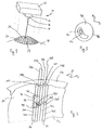
- Fig. 1 is a perspective view of a cornea of an eye with an imaginary reference field (grid) superposed thereon;
- Fig. 2 is a perspective view of a portion of the cornea of an eye showing the geometrical relationships between the corneal anatomy and the focal spot of an incising laser beam; and
- Fig. 3 is a plan view of a refractive power map of a cornea.
-
- Referring initially to Fig. 1, an ophthalmic laser apparatus prepared by a method of the present invention is shown and is generally designated 10. As shown, the
device 10 includes alaser source 12 which is capable of generating a non-ultraviolet, ultrashort-pulsed incisinglaser beam 14. Focusingoptics 16, which have components that are well-known in the pertinent art, are provided for directing and focusing the incisinglaser beam 14. As intended for the present invention, the focusingoptics 16 will direct the incisinglaser beam 14 toward theeye 18. More specifically, the focusingoptics 16 will focus the incisinglaser beam 14 either onto thecornea 20 for plasma mediated (non-UV) photoablation of superficial tissue, or into the stroma of thecornea 20 for intrastromal photodisruption of tissue (i.e. photoalteration). - Fig. 1 also shows that the
device 10 includes areference unit 22 that will be used to establish a reference field (i.e. imaginary grid) 24 on theanterior surface 26 of thecornea 20. Specifically, as envisioned for the present invention, the imaginary reference field (grid) 24 is electronically generated by thereference unit 22 to identify a plurality of reference areas 28 on theanterior surface 26. These reference areas 28 can then be used for purposes of controlling the direction of the incisinglaser beam 14 toward thecornea 20. As shown in Fig. 2, thespecific reference areas cornea 20. Stated differently, in practice, the reference areas 28 will be electrically identified in thereference unit 22, and will not necessarily be visible on theanterior surface 26 of thecornea 20. - With reference now to Fig. 2, it will be appreciated that the
respective reference areas 28a-d can be used to establish reference volumes 30a-d that extend through the stroma of thecornea 20. More specifically, each reference volume 30 extends through thecornea 20 from theanterior surface 26 to theposterior surface 32. The actual size of each reference volume 30 will thus depend on the thickness of thecornea 20 and the lengths of thex-dimension 34 and γ-dimension 36 of the respective reference area 28. As envisioned for the present invention, thex-dimension 34 and the y-dimension 36 will preferably be around ten microns in length. - Fig. 2 also shows that within a particular reference volume 30 a
length 38 can be established which will define atissue volume 40. For example, thetissue volume 40 shown in Fig. 2 is located within a projection of thereference area 28a through thecornea 20, and is bounded between theend 42 and theend 44. As will be appreciated by the skilled artisan, the size of atissue volume 40 will depend on the size of the respective reference area 28 and the extent oflength 38. For the purposes of the present invention, the extent oflength 38 is diagnostically determined. - Fig. 3 is a plan view of a representative
refractive power map 46 that has been diagnostically determined for acornea 20. As indicated above, arefractive power map 46 can be generated using optical techniques that are well known in the pertinent art, such as by wavefront analysis. Once generated, therefractive power map 46 effectively indicates those portions of thecornea 20 that contribute to the optical aberrations. For example, if thearea 48 of therefractive power map 46 is considered equivalent to anormal eye 18, thearea 50 will indicate a deviation from this norm that requires some optical correction. Specifically, the correction required for the deviation will be stated in diopters. Further, thearea 52 will indicate a deviation from the norm where additional optical correction is required. With theareas areas 50 and 52), will result in the desired optical correction. - In the operation of the
device 10 of the present invention, therefractive power map 46 for thecornea 20 is created first. Themap 46 is then analyzed to identify areas on themap 46 that correspond with the imaginary reference field (grid) 24 that is generated in thereference unit 22. Thus, themap 46 is correlated with reference areas 28 of the reference field (grid) 24 and the contribution each reference volume 30 makes to the optical aberrations ofcornea 20 is determined. Based on this information, the size of thetissue volume 40 that is to be removed from the reference volume 30 is determined. - In order to remove tissue from the
cornea 20, thelaser source 12 is activated, and the focusingoptics 16 are also activated to direct an incisinglaser beam 14 along a beam path 54. As shown, with this control, the incisinglaser beam 14 can be directed toward a preselected reference area 28 on theanterior surface 26 of the cornea 20 (thebeam paths laser beam 14 can be directed along the beam path 54b for incidence on the reference area 28b. The incisinglaser beam 14, when so directed, can then be focused onto the reference area 28b, or be passed through the reference area 28b and focused to afocal spot 56b in the reference volume 30b. In either case, the incisinglaser beam 14 is focused in a manner which will cause it to photoalter the tissue at the focal spot 56. - As intended for the present invention, the incising
laser beam 14 can be selectively redirected to move from one focal spot 56 to another focal spot 56. Also, the incisinglaser beam 14 can be moved from a focal spot 56 in one reference volume 30 to a focal spot 56 in another reference volume 30. For example, the incisinglaser beam 14 can be focused to thefocal spot 56b in reference volume 30b and, subsequently, focused to thefocal spot 56b' in the reference volume 30b. Similarly, the incisinglaser beam 14 can be subsequently focused to thefocal spot 56d in reference volume 30d. Thus, the focal spot 56 of the incisinglaser beam 14 can be moved, as desired, in the x-direction and in the y-direction. Additionally, the focal spot can be moved along thelength 38 in a predetermined tissue volume 40 (Z direction). In this manner, predetermined volumes of stromal tissue, such as a lenticle, can be isolated in the stroma for subsequent removal. Also, layers of stromal tissue can be photoaltered to create passageways through the stroma. Further, whole volumes of tissue can be photoaltered, and the resultant debris removed. In each case, the removal of stromal tissue can be customized. Stated differently, the objective is to remove the stromal tissue, and only the stromal tissue, that will make whatever optical corrections are necessary. - While the particular Method as herein shown and disclosed in detail is fully capable of obtaining the objects and providing the advantages herein before stated, it is to be understood that it is merely illustrative of the presently preferred embodiments of the invention and that no limitations are intended to the details of construction or design herein shown other than as described in the appended claims.
Claims (15)
- A method for preparing an apparatus for customizing corneal corrections which apparatus comprises an incising laser beam and wherein the method comprises the step of superposing a reference field on the anterior surface of the cornea of an eye to divide the corneal surface into a plurality of reference areas which are suitable for:directing the incising laser beam along a beam path to a focal spot, to photoalter stromal tissue at said focal spot; and forselectively moving said focal spot along said beam path to photoalter stromal tissue along a predetermined length of said beam path; and forredirecting said incising beam through another said reference area to photoalter stromal tissue.
- A method as recited in claim 1 wherein said reference areas are suitable for corresponding with a refractive power map of the cornea and directing the selective movement of said incising laser beam to effectuate said refractive power correction for said reference area.
- A method as recited in claim 2 wherein said refractive power map is a corneal topograph.
- A method as recited in claim 2 wherein said refractive power map is produced using a wavefront analysis.
- A method as recited in claim 1 wherein each said reference area has an x-dimension and a y-dimension.
- A method as recited in claim 5 wherein said x-dimension is substantially equal to said y-dimension, and further wherein said x-dimension and said y-dimension are equal to approximately five microns.
- A method as recited in claim 1 wherein the plurality of reference areas are suitable for directing an incising laser beam which is created using a non-ultraviolet ultrashort-pulsed laser.
- A method as recited in claim 7 wherein said incising laser beam comprises a plurality of pulses with each said pulse having a duration greater than approximately ten femptoseconds.
- A method for preparing an apparatus for surgically correcting optical aberrations of an eye which apparatus comprises an incising laser beam and wherein the method comprises the step of establishing a plurality of reference volumes in the cornea of the eye, which reference volumes are suitable for:identifying a contribution from each said reference volume associated with the optical aberrations; and fordetermining a tissue volume in each said reference volume; and fordirecting an incising laser beam along a beam path to photoalter said tissue volume therein and thus eliminating the contribution from said reference volume to the optical aberrations; and forredirecting said incising laser beam into other said reference volumes to respectively photoalter said tissue volumes therein and thus eliminating the contribution from each said reference volumes to the optical aberrations.
- A method as recited in claim 9 wherein said establishing step further comprises the steps of:superposing a reference field on the anterior surface of the cornea to divide the corneal surface into a plurality of reference areas; andprojecting each said reference area from the anterior surface through the cornea to define respective said reference volumes.
- A method as recited in claim 10 wherein said reference volumes are suitable for corresponding with a refractive power map of the cornea to determine the contribution from each said reference volume associated with the optical aberrations.
- A method as recited in claim 9 wherein reference volumes are suitable for directing and for redirecting said incising lase beam by focussing said incising laser beam to a focal spot in said reference volume; and by selectively moving said focal spot along said beam path to photoalter stromal tissue along a predetermined length of said beam path.
- A method as recited in claim 9 wherein reference volumes are suitable for directing an incising laser beam which is created using a non-ultraviolet ultrashort-pulsed laser wherein said incising laser beam comprises a plurality of pulses with each said pulse having a duration greater than approximately ten femptoseconds.
- An apparatus for customizing corneal corrections which comprises:a means for superposing a reference field on the anterior surface of the cornea of an eye to divide the corneal surface into a plurality of reference areas;a means for directing an incising laser beam along a beam path through one said reference area to a focal spot to photoalter stromal tissue at said focal spot;a means for selectively moving said focal spot along said beam path to photoalter stromal tissue along a predetermined length of said beam path; anda means for redirecting said incising beam through another said reference area to photoalter stromal tissue.
- An apparatus as recited in claim 14 further comprising:a means for creating a refractive power map for the cornea;a means for corresponding said refractive power map with said reference field to determine a refractive power correction for each said reference area; anda means for activating said incising laser beam during said selectively moving step to effectuate said refractive power correction for said reference area.
Applications Claiming Priority (2)
| Application Number | Priority Date | Filing Date | Title |
|---|---|---|---|
| US609090 | 2000-06-30 | ||
| US09/609,090 US6648877B1 (en) | 2000-06-30 | 2000-06-30 | Method for custom corneal corrections |
Publications (3)
| Publication Number | Publication Date |
|---|---|
| EP1169985A2 true EP1169985A2 (en) | 2002-01-09 |
| EP1169985A3 EP1169985A3 (en) | 2003-11-26 |
| EP1169985B1 EP1169985B1 (en) | 2007-01-17 |
Family
ID=24439312
Family Applications (1)
| Application Number | Title | Priority Date | Filing Date |
|---|---|---|---|
| EP01301727A Expired - Lifetime EP1169985B1 (en) | 2000-06-30 | 2001-02-26 | Apparatus for customizing corneal corrections |
Country Status (5)
| Country | Link |
|---|---|
| US (1) | US6648877B1 (en) |
| EP (1) | EP1169985B1 (en) |
| JP (1) | JP2002058697A (en) |
| CA (1) | CA2323842C (en) |
| DE (1) | DE60126019T2 (en) |
Cited By (2)
| Publication number | Priority date | Publication date | Assignee | Title |
|---|---|---|---|---|
| WO2007006470A1 (en) * | 2005-07-08 | 2007-01-18 | Carl Zeiss Meditec Ag | Device and method for altering an implanted lens |
| WO2007085891A1 (en) * | 2006-01-25 | 2007-08-02 | 20/10 Perfect Vision Ag | Device and method for calibrating a laser system |
Families Citing this family (51)
| Publication number | Priority date | Publication date | Assignee | Title |
|---|---|---|---|---|
| US7655002B2 (en) | 1996-03-21 | 2010-02-02 | Second Sight Laser Technologies, Inc. | Lenticular refractive surgery of presbyopia, other refractive errors, and cataract retardation |
| US8668735B2 (en) | 2000-09-12 | 2014-03-11 | Revision Optics, Inc. | Corneal implant storage and delivery devices |
| WO2002021965A1 (en) | 2000-09-12 | 2002-03-21 | Anamed, Inc. | System for packaging and handling an implant and method of use |
| US7776086B2 (en) | 2004-04-30 | 2010-08-17 | Revision Optics, Inc. | Aspherical corneal implant |
| US10835371B2 (en) | 2004-04-30 | 2020-11-17 | Rvo 2.0, Inc. | Small diameter corneal inlay methods |
| US8057541B2 (en) | 2006-02-24 | 2011-11-15 | Revision Optics, Inc. | Method of using small diameter intracorneal inlays to treat visual impairment |
| US8394084B2 (en) | 2005-01-10 | 2013-03-12 | Optimedica Corporation | Apparatus for patterned plasma-mediated laser trephination of the lens capsule and three dimensional phaco-segmentation |
| US10842675B2 (en) | 2006-01-20 | 2020-11-24 | Lensar, Inc. | System and method for treating the structure of the human lens with a laser |
| US8262646B2 (en) | 2006-01-20 | 2012-09-11 | Lensar, Inc. | System and method for providing the shaped structural weakening of the human lens with a laser |
| US9545338B2 (en) | 2006-01-20 | 2017-01-17 | Lensar, Llc. | System and method for improving the accommodative amplitude and increasing the refractive power of the human lens with a laser |
| US9889043B2 (en) | 2006-01-20 | 2018-02-13 | Lensar, Inc. | System and apparatus for delivering a laser beam to the lens of an eye |
| US10555805B2 (en) | 2006-02-24 | 2020-02-11 | Rvo 2.0, Inc. | Anterior corneal shapes and methods of providing the shapes |
| US8182471B2 (en) | 2006-03-17 | 2012-05-22 | Amo Manufacturing Usa, Llc. | Intrastromal refractive correction systems and methods |
| DE502006009159D1 (en) * | 2006-05-31 | 2011-05-05 | Ziemer Holding Ag | Ophthalmological device |
| US20070282312A1 (en) * | 2006-05-31 | 2007-12-06 | Sie Ag Surgical Instrument Engineering | Ophthalmologic apparatus |
| EP2772234B1 (en) | 2007-03-13 | 2021-05-26 | AMO Development, LLC | Apparatus for creating ocular surgical and relaxing incisions |
| US9271828B2 (en) | 2007-03-28 | 2016-03-01 | Revision Optics, Inc. | Corneal implant retaining devices and methods of use |
| US8162953B2 (en) | 2007-03-28 | 2012-04-24 | Revision Optics, Inc. | Insertion system for corneal implants |
| US9549848B2 (en) | 2007-03-28 | 2017-01-24 | Revision Optics, Inc. | Corneal implant inserters and methods of use |
| WO2009124136A1 (en) * | 2008-04-01 | 2009-10-08 | Amo Development, Llc | System and method of iris-pupil contrast enhancement |
| EP2334270B1 (en) * | 2008-04-01 | 2016-06-01 | AMO Development, LLC | Ophthalmic laser apparatus and system with high resolution imaging |
| US9539143B2 (en) | 2008-04-04 | 2017-01-10 | Revision Optics, Inc. | Methods of correcting vision |
| WO2009124268A2 (en) | 2008-04-04 | 2009-10-08 | Revision Optics, Inc. | Corneal inlay design and methods of correcting vision |
| EP2111831B1 (en) * | 2008-04-22 | 2010-01-20 | WaveLight AG | Device for laser optic eye surgery |
| US8500723B2 (en) | 2008-07-25 | 2013-08-06 | Lensar, Inc. | Liquid filled index matching device for ophthalmic laser procedures |
| US8480659B2 (en) | 2008-07-25 | 2013-07-09 | Lensar, Inc. | Method and system for removal and replacement of lens material from the lens of an eye |
| US8377048B2 (en) * | 2009-01-06 | 2013-02-19 | Technolas Perfect Vision Gmbh | Minimizing the side-effects of refractive corrections using statistically determined irregularities in intrastromal incisions |
| DE102009005482A1 (en) * | 2009-01-21 | 2010-07-22 | Carl Zeiss Meditec Ag | Device and method for generating control data for the surgical ametropia correction of an eye |
| US8366701B2 (en) * | 2009-01-27 | 2013-02-05 | Technolas Perfect Vision Gmbh | System and method for correcting higher order aberrations with changes in intrastromal biomechanical stress distributions |
| WO2010091419A1 (en) | 2009-02-09 | 2010-08-12 | Amo Development Llc. | System and method for intrastromal refractive correction |
| US8758332B2 (en) | 2009-07-24 | 2014-06-24 | Lensar, Inc. | Laser system and method for performing and sealing corneal incisions in the eye |
| CA2769097A1 (en) | 2009-07-24 | 2011-01-27 | Lensar, Inc. | System and method for performing ladar assisted procedures on the lens of an eye |
| US8382745B2 (en) | 2009-07-24 | 2013-02-26 | Lensar, Inc. | Laser system and method for astigmatic corrections in association with cataract treatment |
| US8617146B2 (en) | 2009-07-24 | 2013-12-31 | Lensar, Inc. | Laser system and method for correction of induced astigmatism |
| JP2013500078A (en) | 2009-07-24 | 2013-01-07 | レンサー, インク. | System and method for irradiating a lens of an eye with a laser irradiation pattern |
| CN102843955A (en) | 2010-02-01 | 2012-12-26 | 雷萨公司 | Purkinjie image-based alignment of suction ring in ophthalmic applications |
| US20160074221A1 (en) * | 2010-06-14 | 2016-03-17 | Marie-Jose B. Tassignon | Femtosecond laser apparatus for plasma induced vitreous ablation in the eye |
| US8469948B2 (en) | 2010-08-23 | 2013-06-25 | Revision Optics, Inc. | Methods and devices for forming corneal channels |
| WO2012051490A1 (en) | 2010-10-15 | 2012-04-19 | Lensar, Inc. | System and method of scan controlled illumination of structures within an eye |
| USD694890S1 (en) | 2010-10-15 | 2013-12-03 | Lensar, Inc. | Laser system for treatment of the eye |
| USD695408S1 (en) | 2010-10-15 | 2013-12-10 | Lensar, Inc. | Laser system for treatment of the eye |
| WO2012135073A2 (en) | 2011-03-25 | 2012-10-04 | Board Of Trustees Of Michigan State University | Adaptive laser system for ophthalmic use |
| US10463541B2 (en) | 2011-03-25 | 2019-11-05 | Lensar, Inc. | System and method for correcting astigmatism using multiple paired arcuate laser generated corneal incisions |
| JP5944005B2 (en) | 2011-10-21 | 2016-07-05 | リヴィジョン・オプティックス・インコーポレーテッド | Corneal graft storage and delivery device |
| US9393154B2 (en) | 2011-10-28 | 2016-07-19 | Raymond I Myers | Laser methods for creating an antioxidant sink in the crystalline lens for the maintenance of eye health and physiology and slowing presbyopia development |
| US20140135752A1 (en) * | 2012-11-09 | 2014-05-15 | Vladislav Duma | System and Method for Configuring Fragmentation Segments of a Crystalline Lens for a Lensectomy |
| WO2016144404A1 (en) | 2015-03-12 | 2016-09-15 | Revision Optics, Inc. | Methods of correcting vision |
| HK1254350A1 (en) | 2015-10-23 | 2019-07-19 | 纽约市哥伦比亚大学理事会 | Laser induced collagen crosslinking in tissue |
| DE102016208011A1 (en) * | 2016-05-10 | 2017-11-16 | Carl Zeiss Meditec Ag | Eye surgery procedure |
| US11497403B2 (en) | 2016-06-10 | 2022-11-15 | The Trustees Of Columbia University In The City Of New York | Devices, methods, and systems for detection of collagen tissue features |
| US11666481B1 (en) | 2017-12-01 | 2023-06-06 | The Trustees Of Columbia University In The City Of New York | Diagnosis and treatment of collagen-containing tissues |
Citations (1)
| Publication number | Priority date | Publication date | Assignee | Title |
|---|---|---|---|---|
| US5993438A (en) | 1993-11-12 | 1999-11-30 | Escalon Medical Corporation | Intrastromal photorefractive keratectomy |
Family Cites Families (6)
| Publication number | Priority date | Publication date | Assignee | Title |
|---|---|---|---|---|
| US4907586A (en) * | 1988-03-31 | 1990-03-13 | Intelligent Surgical Lasers | Method for reshaping the eye |
| US4903695C1 (en) * | 1988-11-30 | 2001-09-11 | Lri L P | Method and apparatus for performing a keratomileusis or the like operation |
| US6099522A (en) * | 1989-02-06 | 2000-08-08 | Visx Inc. | Automated laser workstation for high precision surgical and industrial interventions |
| US5460627A (en) * | 1993-05-03 | 1995-10-24 | O'donnell, Jr.; Francis E. | Method of evaluating a laser used in ophthalmological surgery |
| CA2344586C (en) * | 1998-10-02 | 2008-04-29 | Scientific Optics, Inc. | Method for diagnosing and improving vision |
| AUPP697398A0 (en) * | 1998-11-06 | 1998-12-03 | Lions Eye Institute Of Western Australia Incorporated, The | Eye tracker for refractive surgery |
-
2000
- 2000-06-30 US US09/609,090 patent/US6648877B1/en not_active Expired - Lifetime
- 2000-10-19 CA CA002323842A patent/CA2323842C/en not_active Expired - Fee Related
-
2001
- 2001-02-26 DE DE60126019T patent/DE60126019T2/en not_active Expired - Lifetime
- 2001-02-26 EP EP01301727A patent/EP1169985B1/en not_active Expired - Lifetime
- 2001-07-02 JP JP2001200700A patent/JP2002058697A/en active Pending
Patent Citations (1)
| Publication number | Priority date | Publication date | Assignee | Title |
|---|---|---|---|---|
| US5993438A (en) | 1993-11-12 | 1999-11-30 | Escalon Medical Corporation | Intrastromal photorefractive keratectomy |
Cited By (2)
| Publication number | Priority date | Publication date | Assignee | Title |
|---|---|---|---|---|
| WO2007006470A1 (en) * | 2005-07-08 | 2007-01-18 | Carl Zeiss Meditec Ag | Device and method for altering an implanted lens |
| WO2007085891A1 (en) * | 2006-01-25 | 2007-08-02 | 20/10 Perfect Vision Ag | Device and method for calibrating a laser system |
Also Published As
| Publication number | Publication date |
|---|---|
| CA2323842C (en) | 2009-03-03 |
| JP2002058697A (en) | 2002-02-26 |
| DE60126019D1 (en) | 2007-03-08 |
| EP1169985B1 (en) | 2007-01-17 |
| EP1169985A3 (en) | 2003-11-26 |
| DE60126019T2 (en) | 2007-08-16 |
| CA2323842A1 (en) | 2001-12-30 |
| US6648877B1 (en) | 2003-11-18 |
Similar Documents
| Publication | Publication Date | Title |
|---|---|---|
| CA2323842C (en) | Method for custom corneal corrections | |
| EP1316298B1 (en) | An apparatus for creating a corneal flap | |
| EP1784149B1 (en) | Apparatus and method for correction of aberrations in laser system optics | |
| US11413189B2 (en) | Device and method for producing control data for the surgical correction of defective eye vision | |
| US6610051B2 (en) | Device and method for performing refractive surgery | |
| US7892225B2 (en) | Devices and methods for separating layers of materials having different ablation thresholds | |
| US6451006B1 (en) | Method for separating lamellae | |
| US7238176B2 (en) | Method for intrastromal photodisruption of dome-shaped surfaces | |
| US6110166A (en) | Method for corneal laser surgery | |
| US6610050B2 (en) | Laser beam delivery system with multiple focal points | |
| KR101487895B1 (en) | Ophthalmic refraction correction retreatment | |
| CN109152659B (en) | Ophthalmic surgical method | |
| CN107072816B (en) | eye surgery methods | |
| JP5030785B2 (en) | System and method for scanning patterns in a substrate | |
| US20220409434A1 (en) | Method for controlling an eye surgical laser, treatment apparatus, computer program as well as computer-readable medium | |
| JP2009531079A (en) | Laser mask for creating corneal pockets | |
| KR20140089599A (en) | Laser-assisted epithelial removal | |
| EP1941849B1 (en) | Apparatus for corneal laser surgery | |
| US20120035597A1 (en) | Method for treating incision surfaces in a transparent material |
Legal Events
| Date | Code | Title | Description |
|---|---|---|---|
| PUAI | Public reference made under article 153(3) epc to a published international application that has entered the european phase |
Free format text: ORIGINAL CODE: 0009012 |
|
| AK | Designated contracting states |
Kind code of ref document: A2 Designated state(s): AT BE CH CY DE DK ES FI FR GB GR IE IT LI LU MC NL PT SE TR |
|
| AX | Request for extension of the european patent |
Free format text: AL;LT;LV;MK;RO;SI |
|
| PUAL | Search report despatched |
Free format text: ORIGINAL CODE: 0009013 |
|
| AK | Designated contracting states |
Kind code of ref document: A3 Designated state(s): AT BE CH CY DE DK ES FI FR GB GR IE IT LI LU MC NL PT SE TR |
|
| AX | Request for extension of the european patent |
Extension state: AL LT LV MK RO SI |
|
| 17P | Request for examination filed |
Effective date: 20040524 |
|
| AKX | Designation fees paid |
Designated state(s): AT BE CH CY DE DK ES FI FR GB GR IE IT LI LU MC NL PT SE TR |
|
| 17Q | First examination report despatched |
Effective date: 20041103 |
|
| RTI1 | Title (correction) |
Free format text: APPARATUS FOR CUSTOMIZING CORNEAL CORRECTIONS |
|
| GRAP | Despatch of communication of intention to grant a patent |
Free format text: ORIGINAL CODE: EPIDOSNIGR1 |
|
| RTI1 | Title (correction) |
Free format text: APPARATUS FOR CUSTOMIZING CORNEAL CORRECTIONS |
|
| GRAS | Grant fee paid |
Free format text: ORIGINAL CODE: EPIDOSNIGR3 |
|
| GRAA | (expected) grant |
Free format text: ORIGINAL CODE: 0009210 |
|
| AK | Designated contracting states |
Kind code of ref document: B1 Designated state(s): AT BE CH CY DE DK ES FI FR GB GR IE IT LI LU MC NL PT SE TR |
|
| PG25 | Lapsed in a contracting state [announced via postgrant information from national office to epo] |
Ref country code: CH Free format text: LAPSE BECAUSE OF FAILURE TO SUBMIT A TRANSLATION OF THE DESCRIPTION OR TO PAY THE FEE WITHIN THE PRESCRIBED TIME-LIMIT Effective date: 20070117 Ref country code: AT Free format text: LAPSE BECAUSE OF FAILURE TO SUBMIT A TRANSLATION OF THE DESCRIPTION OR TO PAY THE FEE WITHIN THE PRESCRIBED TIME-LIMIT Effective date: 20070117 Ref country code: NL Free format text: LAPSE BECAUSE OF FAILURE TO SUBMIT A TRANSLATION OF THE DESCRIPTION OR TO PAY THE FEE WITHIN THE PRESCRIBED TIME-LIMIT Effective date: 20070117 Ref country code: FI Free format text: LAPSE BECAUSE OF FAILURE TO SUBMIT A TRANSLATION OF THE DESCRIPTION OR TO PAY THE FEE WITHIN THE PRESCRIBED TIME-LIMIT Effective date: 20070117 Ref country code: LI Free format text: LAPSE BECAUSE OF FAILURE TO SUBMIT A TRANSLATION OF THE DESCRIPTION OR TO PAY THE FEE WITHIN THE PRESCRIBED TIME-LIMIT Effective date: 20070117 Ref country code: DK Free format text: LAPSE BECAUSE OF FAILURE TO SUBMIT A TRANSLATION OF THE DESCRIPTION OR TO PAY THE FEE WITHIN THE PRESCRIBED TIME-LIMIT Effective date: 20070117 |
|
| REG | Reference to a national code |
Ref country code: GB Ref legal event code: FG4D |
|
| REG | Reference to a national code |
Ref country code: CH Ref legal event code: EP |
|
| PG25 | Lapsed in a contracting state [announced via postgrant information from national office to epo] |
Ref country code: MC Free format text: LAPSE BECAUSE OF NON-PAYMENT OF DUE FEES Effective date: 20070228 |
|
| REG | Reference to a national code |
Ref country code: IE Ref legal event code: FG4D |
|
| REF | Corresponds to: |
Ref document number: 60126019 Country of ref document: DE Date of ref document: 20070308 Kind code of ref document: P |
|
| PG25 | Lapsed in a contracting state [announced via postgrant information from national office to epo] |
Ref country code: SE Free format text: LAPSE BECAUSE OF FAILURE TO SUBMIT A TRANSLATION OF THE DESCRIPTION OR TO PAY THE FEE WITHIN THE PRESCRIBED TIME-LIMIT Effective date: 20070417 |
|
| PG25 | Lapsed in a contracting state [announced via postgrant information from national office to epo] |
Ref country code: ES Free format text: LAPSE BECAUSE OF FAILURE TO SUBMIT A TRANSLATION OF THE DESCRIPTION OR TO PAY THE FEE WITHIN THE PRESCRIBED TIME-LIMIT Effective date: 20070428 |
|
| PG25 | Lapsed in a contracting state [announced via postgrant information from national office to epo] |
Ref country code: PT Free format text: LAPSE BECAUSE OF FAILURE TO SUBMIT A TRANSLATION OF THE DESCRIPTION OR TO PAY THE FEE WITHIN THE PRESCRIBED TIME-LIMIT Effective date: 20070618 |
|
| NLV1 | Nl: lapsed or annulled due to failure to fulfill the requirements of art. 29p and 29m of the patents act | ||
| ET | Fr: translation filed | ||
| REG | Reference to a national code |
Ref country code: CH Ref legal event code: PL |
|
| PLBE | No opposition filed within time limit |
Free format text: ORIGINAL CODE: 0009261 |
|
| STAA | Information on the status of an ep patent application or granted ep patent |
Free format text: STATUS: NO OPPOSITION FILED WITHIN TIME LIMIT |
|
| 26N | No opposition filed |
Effective date: 20071018 |
|
| PG25 | Lapsed in a contracting state [announced via postgrant information from national office to epo] |
Ref country code: BE Free format text: LAPSE BECAUSE OF FAILURE TO SUBMIT A TRANSLATION OF THE DESCRIPTION OR TO PAY THE FEE WITHIN THE PRESCRIBED TIME-LIMIT Effective date: 20070117 |
|
| PG25 | Lapsed in a contracting state [announced via postgrant information from national office to epo] |
Ref country code: IE Free format text: LAPSE BECAUSE OF NON-PAYMENT OF DUE FEES Effective date: 20070226 |
|
| PG25 | Lapsed in a contracting state [announced via postgrant information from national office to epo] |
Ref country code: GR Free format text: LAPSE BECAUSE OF FAILURE TO SUBMIT A TRANSLATION OF THE DESCRIPTION OR TO PAY THE FEE WITHIN THE PRESCRIBED TIME-LIMIT Effective date: 20070418 |
|
| REG | Reference to a national code |
Ref country code: FR Ref legal event code: CA |
|
| REG | Reference to a national code |
Ref country code: FR Ref legal event code: CA |
|
| PG25 | Lapsed in a contracting state [announced via postgrant information from national office to epo] |
Ref country code: CY Free format text: LAPSE BECAUSE OF FAILURE TO SUBMIT A TRANSLATION OF THE DESCRIPTION OR TO PAY THE FEE WITHIN THE PRESCRIBED TIME-LIMIT Effective date: 20070117 |
|
| PG25 | Lapsed in a contracting state [announced via postgrant information from national office to epo] |
Ref country code: LU Free format text: LAPSE BECAUSE OF NON-PAYMENT OF DUE FEES Effective date: 20070226 |
|
| PG25 | Lapsed in a contracting state [announced via postgrant information from national office to epo] |
Ref country code: TR Free format text: LAPSE BECAUSE OF FAILURE TO SUBMIT A TRANSLATION OF THE DESCRIPTION OR TO PAY THE FEE WITHIN THE PRESCRIBED TIME-LIMIT Effective date: 20070117 |
|
| PG25 | Lapsed in a contracting state [announced via postgrant information from national office to epo] |
Ref country code: IT Free format text: LAPSE BECAUSE OF NON-PAYMENT OF DUE FEES Effective date: 20090226 |
|
| REG | Reference to a national code |
Ref country code: FR Ref legal event code: PLFP Year of fee payment: 16 |
|
| REG | Reference to a national code |
Ref country code: FR Ref legal event code: PLFP Year of fee payment: 17 |
|
| REG | Reference to a national code |
Ref country code: FR Ref legal event code: PLFP Year of fee payment: 18 |
|
| PGFP | Annual fee paid to national office [announced via postgrant information from national office to epo] |
Ref country code: DE Payment date: 20190212 Year of fee payment: 19 Ref country code: GB Payment date: 20190220 Year of fee payment: 19 Ref country code: FR Payment date: 20190111 Year of fee payment: 19 Ref country code: IT Payment date: 20190221 Year of fee payment: 19 |
|
| REG | Reference to a national code |
Ref country code: DE Ref legal event code: R119 Ref document number: 60126019 Country of ref document: DE |
|
| GBPC | Gb: european patent ceased through non-payment of renewal fee |
Effective date: 20200226 |
|
| PG25 | Lapsed in a contracting state [announced via postgrant information from national office to epo] |
Ref country code: GB Free format text: LAPSE BECAUSE OF NON-PAYMENT OF DUE FEES Effective date: 20200226 Ref country code: FR Free format text: LAPSE BECAUSE OF NON-PAYMENT OF DUE FEES Effective date: 20200229 Ref country code: DE Free format text: LAPSE BECAUSE OF NON-PAYMENT OF DUE FEES Effective date: 20200901 |
|
| PG25 | Lapsed in a contracting state [announced via postgrant information from national office to epo] |
Ref country code: IT Free format text: LAPSE BECAUSE OF NON-PAYMENT OF DUE FEES Effective date: 20200229 |