EP1976112A1 - Elektronischer Verstärkerschaltkreis, der ein Differenzialpaar und ein Gegenkopplungssystem umfasst - Google Patents
Elektronischer Verstärkerschaltkreis, der ein Differenzialpaar und ein Gegenkopplungssystem umfasst Download PDFInfo
- Publication number
- EP1976112A1 EP1976112A1 EP08290259A EP08290259A EP1976112A1 EP 1976112 A1 EP1976112 A1 EP 1976112A1 EP 08290259 A EP08290259 A EP 08290259A EP 08290259 A EP08290259 A EP 08290259A EP 1976112 A1 EP1976112 A1 EP 1976112A1
- Authority
- EP
- European Patent Office
- Prior art keywords
- transistors
- electronic
- voltage
- common mode
- differential pair
- Prior art date
- Legal status (The legal status is an assumption and is not a legal conclusion. Google has not performed a legal analysis and makes no representation as to the accuracy of the status listed.)
- Withdrawn
Links
Images


Classifications
-
- H—ELECTRICITY
- H03—ELECTRONIC CIRCUITRY
- H03F—AMPLIFIERS
- H03F3/00—Amplifiers with only discharge tubes or only semiconductor devices as amplifying elements
- H03F3/45—Differential amplifiers
- H03F3/45071—Differential amplifiers with semiconductor devices only
- H03F3/45479—Differential amplifiers with semiconductor devices only characterised by the way of common mode signal rejection
- H03F3/45632—Differential amplifiers with semiconductor devices only characterised by the way of common mode signal rejection in differential amplifiers with FET transistors as the active amplifying circuit
- H03F3/45636—Differential amplifiers with semiconductor devices only characterised by the way of common mode signal rejection in differential amplifiers with FET transistors as the active amplifying circuit by using feedback means
- H03F3/45641—Measuring at the loading circuit of the differential amplifier
- H03F3/4565—Controlling the common source circuit of the differential amplifier
-
- H—ELECTRICITY
- H03—ELECTRONIC CIRCUITRY
- H03F—AMPLIFIERS
- H03F2203/00—Indexing scheme relating to amplifiers with only discharge tubes or only semiconductor devices as amplifying elements covered by H03F3/00
- H03F2203/45—Indexing scheme relating to differential amplifiers
- H03F2203/45418—Indexing scheme relating to differential amplifiers the CMCL comprising a resistor addition circuit
-
- H—ELECTRICITY
- H03—ELECTRONIC CIRCUITRY
- H03F—AMPLIFIERS
- H03F2203/00—Indexing scheme relating to amplifiers with only discharge tubes or only semiconductor devices as amplifying elements covered by H03F3/00
- H03F2203/45—Indexing scheme relating to differential amplifiers
- H03F2203/45434—Indexing scheme relating to differential amplifiers the CMCL output control signal being a voltage signal
-
- H—ELECTRICITY
- H03—ELECTRONIC CIRCUITRY
- H03F—AMPLIFIERS
- H03F2203/00—Indexing scheme relating to amplifiers with only discharge tubes or only semiconductor devices as amplifying elements covered by H03F3/00
- H03F2203/45—Indexing scheme relating to differential amplifiers
- H03F2203/45471—Indexing scheme relating to differential amplifiers the CSC comprising one or more extra current sources
-
- H—ELECTRICITY
- H03—ELECTRONIC CIRCUITRY
- H03F—AMPLIFIERS
- H03F2203/00—Indexing scheme relating to amplifiers with only discharge tubes or only semiconductor devices as amplifying elements covered by H03F3/00
- H03F2203/45—Indexing scheme relating to differential amplifiers
- H03F2203/45476—Indexing scheme relating to differential amplifiers the CSC comprising a mirror circuit
Definitions
- the present invention relates to an amplifier electronic circuit comprising a differential pair.
- it relates to an electronic circuit comprising a differential pair and a feedback system controlling the output common mode voltage of the amplifier.
- an amplifier electronic circuit comprising an input differential pair receiving two differential input signals and outputting two differential output signals and comprising a feedback system controlling the common mode voltage of exit.
- a differential pair is formed of two identical transistors biased by the same current source or different current sources.
- the differential pair is for example the active part of a differential amplifier.
- the object of the differential pair is the amplification of the difference between two input signals of the differential pair.
- the output voltages of the amplifier are thus composed in practice of a differential mode voltage portion and a common mode voltage portion.
- the output differential mode voltage corresponds to the difference of the input signals amplified by the differential gain and the output common mode voltage corresponds to the sum divided by two of the output signals or in other words to the average of the output signals .
- the common-mode voltage remains close to a predefined value.
- a parameter representative of the quality of a differential amplifier is the common mode rejection rate, known as CMRR (Common Mode Rejection Ratio), and corresponds to the ratio between the differential mode gain and the gain in common mode.
- CMRR Common Mode Rejection Ratio
- the TRMC parameter is maximized when the common mode gain is minimized.
- the output common mode voltage undergoes variations dependent on variations of other circuit parameters.
- any variation in the dimensions of the transistors of the differential pair during its manufacture can cause an imbalance between the branches of the differential amplifier, causing variations in the common mode output voltage.
- a known technique consists of extracting the output common mode voltage, then making a comparison between this extracted voltage and a reference voltage, and finally amplifying the signal resulting from this comparison. This amplified error signal is then fed back into the differential pair through its bias elements.
- This technique allows a good control of the common mode voltage, but its implementation implies a consumption of silicon surface and the increase of the current consumption, due to the addition of additional components dedicated to the extraction of the current. mode voltage common, the comparison of this voltage with a reference voltage and the amplification of the error signal.
- a second technique is to extract information on the input common mode voltage and inject it appropriately into the circuit to compensate for the impact of its variations on the output common mode voltage.
- This technique also requires the addition of components.
- its current consumption is high while it does not have the precision of the first technique. It is indeed just a compensation of the impact of the variations of the input signal on the output common mode voltage and not a control of the output common mode voltage.
- the IEEE document "A 0.5V Bulk-Input Fully Differential Operational Transconductance Amplifier” (Shouri Chatterjee, Yannis Tsividis and Peter Kinget, Department of Electrical Engineering, Columbia University, New York, USA) describes a common mode voltage feedback technique. output on the polarization elements. This technique is also less precise than the first technique, the output common mode voltage not being compared to a reference voltage.
- the aim of the present invention is to solve at least some of the aforementioned drawbacks and to propose an electronic circuit comprising a precise system for controlling the common mode output voltage of an amplifier comprising a completely differential pair at the input, without any high loss of surface and without increasing power consumption.
- the invention relates to an amplifier electronic circuit with at least one amplification stage, the first amplification stage comprising a differential pair comprising two input transistors controlled respectively by two input signals; means for measuring the common mode output voltage of the amplifier; and at least a first and second electronic element, each electronic element comprising a first gate and a second gate, a source and a drain, the first gates of the first and second electronic elements being connected together and to the drain of the first electronic element and forming so a current mirror configuration, one of the second gates of the first and second electronic elements receiving the measured output common mode voltage, the other of the second gates receiving a reference voltage, the first electronic element being traversed by a current reference, the second electronic element being adapted to bias all or part of at least one of the amplification stages.
- the second electronic element is connected to the common source of the transistors of the differential pair.
- the amplifier comprises a third electronic element, the first and second grids of the third electronic element being respectively connected to the first and second grids of the second electronic element, the second and third electronic elements being each connected to one of the transistors of the differential pair.
- the electronic components added to the differential pair are not numerous and therefore the necessary silicon area is reduced, as will be explained later in this document.
- the measured output common mode voltage is applied to the second gate of the second electronic element and the reference voltage is applied to the second gate of the first electronic element.
- the common mode output voltage is for example extracted across the terminals of the transistors of the differential pair.
- the number of amplification stages of the difference of the two input signals applied to the transistors of the differential pair is odd and the output common mode voltage is extracted at the level of the last amplification stage.
- the output common mode voltage is applied to the second gate of the first electronic element and the reference voltage is applied to the second gate of the second electronic element.
- the differential pair belongs to a first amplification stage of the difference of the two input signals applied to the transistors of the differential pair and the amplifying electronic circuit comprises a second amplification stage of this difference, the output common mode voltage. measured being extracted on the terminals of the transistors of the second amplification stage.
- the number of amplification stages of the difference of the two input signals applied to the transistors of the differential pair is even, and the output common mode voltage is extracted at the level of the last amplification stage.
- one of the electronic elements comprises two single-gate transistors connected in parallel.
- these transistors have their "common” source and drain, that is to say that the sources of the constituent transistors of the electronic element are connected to one another and that the drains of these same transistors are connected to each other.
- an element of the electronic elements comprises a double-gate transistor having two grids
- such a transistor is a double-gate transistor.
- multi-gate transistors exhibit better characteristics than conventional single gate transistors, reducing the so-called “short channel” effect due to reduced component size, which one tends with the evolution of the technology.
- This type of transistor also has an additional surface gain.
- an element of the electronic elements comprises a double-gate transistor of FinFet or planar type. This type of transistor is therefore particularly suitable here.
- the means for measuring the output common mode voltage of the differential pair comprise two resistors, placed in series between two outputs of the amplifier delivering the output signals.
- the means for measuring the common mode voltage output from the differential pair comprise capacitors and switches.
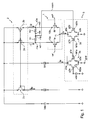
- the differential pair 1 comprises two transistors 1a, 1b coupled by their source.
- these two transistors 1a, 1b are transistors of the type MOS (of the "Metal Oxide Semiconductor") N channel.
- the input voltage signals ve1, ve2 are applied to the gates of the transistors 1a, 1b of the differential pair 1.
- the first voltage signal ve1 is applied to the gate of the first transistor 1a of the differential pair 1 and the second voltage signal ve2 is applied to the gate of the second transistor 1b of the differential pair 1.
- the first output signal vs1 of the amplifier is the voltage on the drain 10a of the first transistor 1a of the differential pair 1 and the second output signal vs2 of the amplifier is the voltage on the drain 10b of the second transistor 1b of the differential pair 1.
- the polarization of the differential pair 1 is carried out by their common source 11 (foot polarization 3) and by each of the drains 10a, 10b of the differential pair 1 (head polarization 2).
- the head polarization 2 is a current mirror providing two copies I1, I2 of an input current Ip.
- This current mirror 2 thus comprises three transistors 2a, 2b, 2c of P-channel MOS type and of identical dimensions in this example.
- the sources of the transistors 2a, 2b, 2c are connected to a supply voltage Vdd, positive in this example.
- the first transistor 2c, diode-mounted, is crossed by the input current Ip.
- the second transistor 2a, and the third transistor 2b polarize the differential pair 1 by the drains 10a, 10b of the transistors 1a, 1b.
- Currents I1, I2 which pass through the second and third transistors 2a, 2b are a copy of (i.e. identical to) the input current Ip passing through the first transistor 2c.
- the foot polarization 3 of the differential pair 1 is made by two electronic elements 3a, 3b.
- Each electronic element 3a, 3b consists of two N-channel MOS parallel transistors in this example.
- the first element 3a comprises two transistors M1a, M2a connected in parallel. Their common sources s3a are connected to the mass gnd. Their common drains d3a are connected to the gate g1a of the first transistor M1a. A reference voltage vctrl is applied to the gate g2a of the second transistor M2a. The two transistors M1a and M2a are connected by their drains to a current source S1 delivering a reference current.
- the second element 3b also comprises two transistors M1b, M2b connected in parallel. Their common s3b sources are also connected to the mass gnd. Their common d3b drains are connected to the common source 11 of the differential pair 1.
- the gate g2b of the second transistor M2b receives the common mode output voltage vcom of the amplifier.
- Is current The total current from the transistors of the differential pair 1a, 1b and distributed in the transistors M1b, M2b of the second element is hereinafter referred to as Is current.
- the first transistor M1a of the first element 3a and the first transistor M1b of the second element 3b are connected in current mirror configuration. That is to say, the gate g1a of the first transistor M1a of the first element 3a is connected to the gate g1b of the first transistor M1b of the second element 3b and to the drains d3a common to the two transistors M1a, M2a of the first element 3a.
- the current flowing through the first transistor M1b of the second element 3b is a copy of the current flowing through the first transistor M1a of the first element 3a.
- the foot polarization 3 of the differential pair 1 is performed by a current source delivering a predefined fixed current.
- the current passing through the second electronic element 3b of the foot bias is variable in order to adjust the output common mode voltage as will become apparent hereinafter.
- the extraction of the common mode output voltage vcom is performed by means of two resistors R1, R2.
- Each of the resistors R1, R2 is connected by a first end r1a, r2a, to each of the outputs of the amplifier, that is to each of the drains 10a, 10b of the transistors 1a, 1b of the differential pair 1 in this example.
- these resistors R1, R2 are connected to each other by their second ends r1b, r2b.
- the two resistors R1, R2 are of identical value.
- the common mode output voltage vcom is measured at the common end r1b, r2b of the two resistors R1, R2.
- the feedback of the common output mode is performed via the foot polarization 3 of the differential pair 1.
- the counter-reaction is performed at the second element 3b of the foot polarization 3 and more precisely from its grid g2b.
- the reference voltage vctrl applied to the transistor M2a is obtained for example by a reference voltage generator circuit.
- a reference voltage generator circuit may simply comprise a diode-mounted MOS transistor and a series resistance between the ground and the supply voltage Vdd.
- the current flowing through this transistor M2b is then greater than the current flowing through the second transistor M2a of the first element 3a, the currents flowing through the first transistor M1a of the first element 3a and the first transistor M1 b of the second element 3b remaining equal by construction.
- the current Is coming from the transistors 1a, 1b of the differential pair 1 increases and becomes greater than the reference current Ia.
- the current draw by the foot bias 3 tends to lower the output voltages vs1, vs2 simultaneously. As a result, the common mode voltage of output vcom decreases.
- the "pseudo" current mirror acts so that the common mode output voltage vcom is increased and equalized to the reference voltage vctrl.
- the common mode output voltage vcom is regulated to a value equal to the reference voltage vctrl and is not subject to variations in the input common mode voltage.
- figure 1 a conventional current mirror formed by two transistors, the first transistor M1a of the first element 3a and the first transistor M1b of the second element 3b.
- the transistors M 1a, M1b are identical, in order to reproduce an identical current.
- the dimensions of the second transistor M2a of the first element 3a and the second transistor M2b of the second element 3b are calculated so as to find a good compromise between the optimal operation of the feedback system of the common mode output voltage vcom and the optimization of the surface.
- the dimensions of these two transistors M2a, M2b are preferably greater than those of the first transistors M1a, M1b of each element for the following reasons.
- the gate voltage g1a of the first transistor M1a of the first element 3a is less and less high until it reaches a voltage close to zero.
- the current mirror formed by the transistors M1a, M1b is then no longer functional.
- the reference voltage vctrl and the common mode output voltage vcom are no longer interactive with each other, that is, the feedback loop ceases to function.
- the differential pair 1 ' consists of two N-channel MOS double-gate transistors 1 a', 1 b '.
- Transistors 1 a', 1 b ' receive on their gates first and second voltages d entry ve1, ve2.
- the voltages present on the drains of the transistors 1a ', 1b' respectively correspond to the first vs1 and second vs2 output voltages of the amplifier.
- the foot polarization 3 ' is a conventional polarization of a differential pair 1' comprising two single-gate transistors 3a ', 3b' of the N-channel MOS type.
- the sources of the transistors 3a ', 3b' are connected to the mass.
- the first transistor 3b ' is diode-mounted and receives a bias current.
- the gates of the transistors 3a ', 3b' are connected one to the other.
- the drain of the second transistor 3a ' is connected to the sources of the transistors of the differential pair 1 a', 1 b 'in order to bias the differential pair 1'.
- the extraction of the common mode voltage output vcom is performed by means of two resistors R1, R2 placed in series between the drains of the transistors 1a ', 1b'.
- the feedback of the common output mode is achieved via the head polarization 2 'of the differential pair 1'.
- the feedback is performed by three elements 2a ', 2b', 2c 'connected in configuration of "pseudo" current mirror.
- Such a configuration provides two currents Is 'which are identical to a reference current le' when the common mode output voltage vcom is equal to a reference voltage vctrl.
- Each electronic element 2a ', 2b', 2c ' is in this example constituted by two single gate transistors connected by their drains and by their sources.
- the transistors are of the P-channel MOS type.
- the sources of the transistors are connected to a supply voltage Vdd.
- the first element 2a ' consists of two transistors M1a', M2a ', the second element 2b' of two transistors M1b ', M2b' and the third element 2c 'of two transistors M1c', M2c '.
- the first transistor M1a 'of the first element 2a' is diode-mounted.
- the gates g1a ', g1b', g1c 'of the first transistors M1a', M1b ', M1c' are connected to each other.
- the first element 2a 'of the "pseudo" current mirror is connected to the reference voltage vctrl. More precisely, the reference voltage vctrl is applied to the gate g2a 'of the second transistor M2a' of the first element 2a '.
- the second element 2b 'and the third element 2c' of the "pseudo" current mirror receive the common mode output voltage vcom.
- the common mode voltage is here taken between the two resistors R1, R2.
- the reference current of the "pseudo" current mirror flows through the first element 2a 'of the current mirror.
- the "pseudo" current mirror provides two identical currents Is', respectively flowing through the second element 2b 'and the third element 2c' of the "pseudo" current mirror.
- each of the elements 2a ', 2b', 2c 'of the "pseudo" mirror of the current is composed of two transistors connected in parallel and the operation and the sizing of the transistors is identical.
- double-gate transistor in the present application means a transistor comprising a single drain zone, a single source zone and two gates that can be polarized independently of one another.
- the electronic amplifier circuit shown in FIG. figure 3 comprises a differential pair 1 'with common mode feedback designed with double-gate transistors, such as that of the circuit shown in FIG. figure 2 .
- the operation of this circuit is similar to that described in relation to the figure 1 .
- the head polarization is similar to that of the circuit shown in FIG. figure 1 except that the single-gate transistors are replaced by P-channel MOS double-gate transistors 2a “, 2b", 2c ".
- the sources of transistors 2a”, 2b “, 2c” are connected to the supply voltage Vdd .
- the gates of the first transistor 2c" are connected to the drain of this transistor and to a current source delivering a bias current Ip.
- the drains of the second and third transistors 2a “, 2b” are respectively connected to the drains of the transistors 1a ', 1b' of the differential pair 1 '.
- the extraction of the output common mode voltage vcom is carried out by means of two resistors R1, R2 in series between the drains of the transistors 1a ', 1b' of the differential pair 1 '.
- the feedback of the common output mode is achieved via the foot polarization 3 "of the differential pair 1 '. similar to the foot 3 polarization of the circuit shown in figure 1 except that each element here consists of a single double-gate transistor.
- the elements 3a “, 3b” connected in configuration of "pseudo” current mirror each comprise a single double-gate transistor.
- the sources of the elements or transistors 3a “, 3b” are connected to ground.
- the first gate g1a “of the first transistor 3a” is connected to the first gate g1b "of the second transistor 3b".
- the first gate g1a “of the first transistor 3a” is connected to the drain of this transistor.
- the second gate g2a “of the first transistor 3a” receives the reference voltage vctrl and the second gate g2b “of the second transistor 3b” receives the common mode voltage output vcom.
- a double-gate transistor has an operation equivalent to that of two parallel transistors connected by their sources and their drains.
- the double-gate transistors may be planar double-gate transistors or FinFET transistors.
- double-gate transistors reduces the area compared to the use of two transistors in parallel.
- a double-gate transistor is much less sensitive to the problem of recess explained above in connection with the figure 1 .
- the reference voltage vctrl applied to the second gate g2a "of the first transistor 3a" can be chosen relatively high without the voltage on the first gate g1a "of the first transistor 3a” becomes lower than the step voltage beyond which the pseudo current mirror is no longer functional.
- the use of a double-gate transistor in the foot or control bias circuit makes it possible to use the desired reference voltage without having to increase the size of the transistors used in this circuit. polarization to avoid problems of staggering.
- asymmetrical double-gate transistors Such transistors have a first grid more influential than the second gate in terms of conduction of the transistor.
- the reference voltage vctrl is then applied to the first gate of the asymmetric transistor.
- FIG. 4 To the figure 4 is shown a fourth embodiment of an amplifier comprising a differential pair 1 with common mode feedback according to the invention.
- the differential pair 1 is identical to that of the circuit represented in FIG. figure 1 .
- the head polarization 2 ' is a polarization identical to that used in the third embodiment, shown in FIG. figure 3 .
- the amplifier circuit includes a second amplification stage making it possible to increase the gain of the amplifier circuit.
- This second stage comprises p-channel MOS transistors 4a, 4b.
- the sources of transistors 4a, 4b are connected to the supply voltage Vdd.
- the transistors 4a, 4b are respectively connected to the drains of the transistors 1a, 1b of the differential pair 1.
- a current mirror configuration 4 polarizes these two transistors 4a, 4b of the second amplification stage.
- the first output signal vs1 is the voltage at the drain 40a of the first transistor 4a of the second amplification stage and the second output signal vs2 is the voltage at the drain 40b of the second transistor 4b of the second stage of amplification.
- the extraction of the common mode voltage output vcom is performed by two resistors R1, R2, in the same way as in the previous embodiments. Note that this time, the extraction is performed at the second amplification stage.
- the common-mode feedback is achieved via a foot bias 3 "of the differential pair 1.
- the foot bias 3" of the differential pair 1 is realized by means of a first electronic element 3a "'and a second electronic element 3b "'.
- each of the electronic elements 3a “', 3b"' connected in "pseudo" current mirror configuration comprises a double-gate transistor of the N-channel MOS type.
- the first gate g1a "'of the first transistor or element 3a"' is connected to the first gate g1b "'of the second transistor or element 3b"'.
- the first gate g1a "'of the first transistor or element 3a"' is connected to the drain of this transistor.
- the second gate g2a "'of the first transistor or element 3a"' receives the common mode output voltage vcom (and not the reference voltage vctrl); and the second gate g2b “'of the second transistor or element 3b”' receives the reference voltage vctrl (and not the common mode output voltage vcom).
- the gain of the amplifier is negative and it is thus necessary to reverse the connection of the common mode output and reference voltages on the electronic elements 3a "'. and 3b "'of the foot polarization.
- all of the transistors of the circuit may be single-gate transistors, multiple gate transistors or a portion of each type.
- the differential pair 1 “comprises two P-channel MOS transistors 1a", 1b ".
- the sources of the transistors 1a", 1b are connected to the supply voltage Vdd.
- the transistors 1a", 1b “respectively receive on their grids input voltages ve1 and ve2.
- the amplifier further comprises two transistors 5a, 5b mounted "cascode" between a head polarization 2 and a foot polarization 3 "".
- Transistors 5a, 5b are N-channel MOS single-gate transistors. Grids g5a, g5b of the two transistors 5a, 5b are connected to each other. This common gate g5a, g5b receives a bias voltage vcasc, which can be generated by a circuit external to the amplifier circuit or by an inner element to the amplifier circuit. As an illustration, the bias voltage vcasc can be generated by means of a system in current mirror configuration.
- the head polarization 2 is a conventional polarization identical to that described for the first embodiment, represented in FIG. figure 1 .
- the transistors 5a, 5b connected to the transistors 1a ", 1b" of the differential pair 1 make it possible to obtain a low input resistance and consequently a voltage on each of the drains a", d1b "which varies little, unlike the pairs classical differentials.
- the foot polarization 3 "" is produced by means of three N-channel MOS double-gate transistors 3a “", 3b “", 3c "".
- the sources of the transistors 3a “", 3b “”, 3c “” are connected to the mass.
- the first grids g1a “", g1b “”, g1c “” of the transistors 3a “", 3b “”, 3c “” are connected to each other.
- the first gate g1a “” of the first transistor 3a “” is connected to the drain of the latter.
- the second gate g2a “" of the first transistor 3a “” receives the reference voltage vctrl.
- the second g2b “” g2c “” gates of the second and third transistors 3b “", 3c “” receive the common mode output voltage vcom.
- the first output voltage vs1 of the amplifier is the voltage at the drain d5a of the transistor 5a and the second output voltage vs2 of the amplifier is the voltage at the drain d5b of the transistor 5b.
- the extraction of the common mode voltage output vcom is performed by an extraction circuit 6 (shown in FIG. figure 6 ) with two inputs and one output.
- a first input 6a receives the first output voltage vs1 and the second input 6b receives the second output voltage vs2.
- the output 6c delivers a voltage equal to the common mode output voltage vcom.
- the common-mode feedback is performed via the foot bias 3 "of the differential pair 1" in a manner similar to that described for the first embodiment, shown in FIG. figure 1 .
- the extraction circuit 6 represented in figure 6 comprises three capacitors C1, C2, C3. It also comprises four switches i1, i2, i3, i4 actuated by two binary signals ⁇ 1, ⁇ 2 of antagonistic activation or non-overlapping signals.
- the signal ⁇ 1 actuates the first switch i1 and the third i3.
- the signal ⁇ 2 actuates the second switch i2 and the fourth i4.
- the first and second switches i1, i2 are placed in series between the first input 6a and the output 6c of the extraction circuit.
- the third and fourth switches i3, i4 are placed in series between the second input 6b and the output 6c of the extraction circuit.
- the first capacitor C1 is placed between the ground and the intermediate node between the first switches i1 and the second switch i2.
- the second capacitor C2 is placed between the ground and the intermediate node between the third switch i3 and the fourth switch i4.
- the third capacitor C3 is placed between the ground and the output 6c of the extraction circuit.
- the signals ⁇ 1, ⁇ 2 control the common mode extraction circuit as described below in relation to the timing diagram represented in FIG. figure 7 .
- the three capacitors C1, C2, C3 are discharged or preloaded to the desired reference voltage for the common mode voltage.
- the first signal ⁇ 1 When the first signal ⁇ 1 is activated (high signal level), it causes the closing of the first and third switches i1, i3. The signal ⁇ 2 is then inactive (low signal level) and the second and fourth switches i2, i4 are open.
- the voltage across the first capacitor C1 becomes equal to the first output voltage vs1 and the voltage across the second capacitor C2 becomes equal to the second output voltage vs2.
- the first signal ⁇ 1 is then deactivated and for a short period of time the two signals ⁇ 1, ⁇ 2 are inactivated (the two signals are in the low state).
- the second signal ⁇ 2 is then activated (high signal level) and the first signal ⁇ 1 remains inactive (low signal level).
- the first and third switches i1, i3 remain open and the second and fourth switches i2, i4 are closed.
- the first and second signals ⁇ 1, ⁇ 2 are then inactivated for a short period of time.
- the common mode output voltage vcom is thus proportional to the output voltages vs1, vs2 of the amplifier.
- vcom VS ⁇ 1 VS ⁇ 1 + VS ⁇ 2 + VS ⁇ 3 ⁇ vs ⁇ 1 + VS ⁇ 2 VS ⁇ 1 + VS ⁇ 2 + VS ⁇ 3 ⁇ vs ⁇ 2
- the output voltage 6c of the extraction circuit is in fact proportional to the common mode output voltage.
- the output voltage 6c progressively changes from an initial value, for example zero, to a value equal to the effective common mode voltage of the amplifier.
- the output voltage 6c of the extraction circuit follows the variations of the common mode output voltage of the amplifier.
- this mode of extraction of the output common mode voltage can be used in any type of amplifier circuit according to the present invention.
- the sources of the transistors of the differential pair 1 "could be connected to the supply voltage by means of a head polarization identical to the head polarization 2 of the amplifier circuit represented in FIG. figure 1 .
- the foot polarization 3 "" is replaced by a conventional polarization, for example of the current mirror type, with a predefined fixed current, and a difference between the differential pair 1 "and the power supply Vdd is introduced between a head polarization 2 'identical to that used in the circuit of the figure 2 .
- the feedback of the common output mode is then performed on the leading polarization of the differential pair 1 ".
- FIG. 8 a sixth embodiment of an amplifier comprising a differential pair 1 with common mode feedback according to the invention.
- This embodiment is particularly suitable when the supply voltage Vdd of the amplifier is low, for example less than 1 volt.
- the differential pair 1 is identical to that of the circuit represented in FIG. figure 1 .
- the sources of the two transistors 1a, 1b are here directly connected to the ground.
- Transistors 1a, 1b respectively receive the input voltages ve1, ve2.
- the voltages present on the drains of the transistors 1a, 1b respectively correspond to the first vs1 and second vs2 output voltages of the amplifier.
- the differential pair 1 is connected to a head polarization 2 'identical to that of the circuit represented in FIG. figure 2 .
- the output common mode voltage is extracted by means of two resistors R1, R2 in series between the drains of the transistors 1a, 1b of the differential pair.
- the regulation of the variations of the output common mode voltage can be explained as follows.
- the transistors of the differential pair 1 a, 1 b are equivalent to resistors.
- the current Is' supplied by the bias to each transistor of the differential pair 1a, 1b increases.
- the output voltages vs1, vs2 increase and consequently the common mode output voltage vcom goes back up.
- the current Is' decreases.
- the output voltages vs1, vs2 decrease and the common mode voltage output vcom decreases.
- the technique of feedback of the common output mode operates for any type of amplifier circuit comprising one or more amplification stages.
- the feedback of the common output mode can be performed on the first amplification stage or on a subsequent stage. It should be noted, however, that a feedback on the first amplification stage is preferable because it makes it possible to provide "cascode" regulation on all subsequent stages.
- the output common mode voltage is applied in a foot or head polarization where the feedback is either on the electronic element of the pseudo-current mirror which is partially diode-mounted and which receives the reference current (1c) on the other (or the other) electronic element (s) of the pseudo-current mirror.
- the output common mode voltage can easily define the place of application of the output common mode voltage depending on the type of amplifier used.
- the present invention furthermore makes it possible to control the value of the common mode output voltage of the amplifier and to reduce the dependence of the latter on the variations of other parameters of the circuit.
- part of the transistors of the circuit may be single-gate transistors and another part may be multi-gate transistors.
- the electronic elements may comprise two transistors connected in parallel or a single double-gate transistor.
- the operation of two transistors connected in parallel is equivalent to that of a double-gate transistor.
- the amplifying electronic circuit may comprise several amplification stages.
- amplifying circuits described above can be made in complementary logic by replacing the P-channel MOS transistors with N-channel transistors and vice versa.
Landscapes
- Engineering & Computer Science (AREA)
- Power Engineering (AREA)
- Amplifiers (AREA)
Applications Claiming Priority (1)
| Application Number | Priority Date | Filing Date | Title |
|---|---|---|---|
| FR0754069A FR2914516B1 (fr) | 2007-03-27 | 2007-03-27 | Circuit electronique amplificateur comprenant une paire differentielle et un systeme de contre-reaction. |
Publications (1)
| Publication Number | Publication Date |
|---|---|
| EP1976112A1 true EP1976112A1 (de) | 2008-10-01 |
Family
ID=38645877
Family Applications (1)
| Application Number | Title | Priority Date | Filing Date |
|---|---|---|---|
| EP08290259A Withdrawn EP1976112A1 (de) | 2007-03-27 | 2008-03-19 | Elektronischer Verstärkerschaltkreis, der ein Differenzialpaar und ein Gegenkopplungssystem umfasst |
Country Status (3)
| Country | Link |
|---|---|
| US (1) | US7602249B2 (de) |
| EP (1) | EP1976112A1 (de) |
| FR (1) | FR2914516B1 (de) |
Families Citing this family (5)
| Publication number | Priority date | Publication date | Assignee | Title |
|---|---|---|---|---|
| US8130534B2 (en) * | 2009-01-08 | 2012-03-06 | Qualcomm Incorporated | System and method to read and write data a magnetic tunnel junction element |
| US20140292298A1 (en) * | 2013-04-01 | 2014-10-02 | Lsi Corporation | Operational Amplifier-Based Current-Sensing Circuit for DC-DC Voltage Converters and The Like |
| DE102015205714A1 (de) * | 2015-03-30 | 2016-10-06 | Siemens Aktiengesellschaft | Sendeverstärker zum Verstärken eines Signals in einem drahtlosen Übertragungssystem |
| WO2018083797A1 (ja) * | 2016-11-07 | 2018-05-11 | 三菱電機株式会社 | 差動増幅回路及び電圧バッファ回路 |
| US10317925B2 (en) | 2017-03-29 | 2019-06-11 | Texas Instruments Incorporated | Attenuating common mode noise current in current mirror circuits |
Citations (2)
| Publication number | Priority date | Publication date | Assignee | Title |
|---|---|---|---|---|
| US20020149427A1 (en) * | 2000-08-15 | 2002-10-17 | Karl Schrodinger | Differential, complementary amplifier |
| US6664912B1 (en) * | 2002-09-13 | 2003-12-16 | Texas Instruments Incorporated | Preamplifier with improved CMRR and temperature stability and associated amplification method |
Family Cites Families (5)
| Publication number | Priority date | Publication date | Assignee | Title |
|---|---|---|---|---|
| JPS5591213A (en) * | 1978-12-28 | 1980-07-10 | Nippon Gakki Seizo Kk | Output offset control circuit for direct-coupled amplifier |
| IT1201839B (it) * | 1986-08-08 | 1989-02-02 | Sgs Microelettronica Spa | Amplificatore operazionale di potenza cmos ad uscita interamente differenziale |
| US6023196A (en) * | 1998-08-03 | 2000-02-08 | Lucent Technologies Inc. | Bias circuit for transconductance amplifier |
| US6580324B2 (en) * | 2001-09-12 | 2003-06-17 | Agere Systems, Inc. | Apparatus, method and system for common-mode stabilization in circuits having differential operation |
| US7088181B1 (en) * | 2004-03-05 | 2006-08-08 | Marvell International Ltd. | Method and apparatus for common mode control |
-
2007
- 2007-03-27 FR FR0754069A patent/FR2914516B1/fr not_active Expired - Fee Related
-
2008
- 2008-03-19 EP EP08290259A patent/EP1976112A1/de not_active Withdrawn
- 2008-03-26 US US12/056,069 patent/US7602249B2/en not_active Expired - Fee Related
Patent Citations (2)
| Publication number | Priority date | Publication date | Assignee | Title |
|---|---|---|---|---|
| US20020149427A1 (en) * | 2000-08-15 | 2002-10-17 | Karl Schrodinger | Differential, complementary amplifier |
| US6664912B1 (en) * | 2002-09-13 | 2003-12-16 | Texas Instruments Incorporated | Preamplifier with improved CMRR and temperature stability and associated amplification method |
Non-Patent Citations (3)
| Title |
|---|
| GUANGMING YIN ET AL: "A 16-B 320-KHZ CMOS A/D CONVERTER USING TWO-STAGE THIRD-ORDER SIGMA DELTA NOISE SHAPING", IEEE JOURNAL OF SOLID-STATE CIRCUITS, IEEE SERVICE CENTER, PISCATAWAY, NJ, US, vol. 28, no. 6, 1 June 1993 (1993-06-01), pages 640 - 646, XP000378422, ISSN: 0018-9200 * |
| KARANICOLAS A N ET AL: "A HIGH-FREQUENCY FULLY DIFFERENTIAL BICMOS OPERATIONAL AMPLIFIER", IEEE JOURNAL OF SOLID-STATE CIRCUITS, IEEE SERVICE CENTER, PISCATAWAY, NJ, US, vol. 26, no. 3, 1 March 1991 (1991-03-01), pages 203 - 208, XP000222596, ISSN: 0018-9200 * |
| SHOURI CHATTERJEE; YANNIS TSIVIDIS; PETER KINGET.: "A 0.5V Bulk-Input fully differential operational transconductance amplifier", DEPARTMENT OF ELECTRICAL ENGINEERING, COLUMBIA UNIVERSITY, NEW YORK, USA |
Also Published As
| Publication number | Publication date |
|---|---|
| US20080238549A1 (en) | 2008-10-02 |
| FR2914516A1 (fr) | 2008-10-03 |
| US7602249B2 (en) | 2009-10-13 |
| FR2914516B1 (fr) | 2009-06-12 |
Similar Documents
| Publication | Publication Date | Title |
|---|---|---|
| FR2814554A1 (fr) | Circuit d'amplificateur operationnel | |
| CH633670B5 (fr) | Circuit oscillateur a onde rectangulaire pour la mesure du temps. | |
| EP1976112A1 (de) | Elektronischer Verstärkerschaltkreis, der ein Differenzialpaar und ein Gegenkopplungssystem umfasst | |
| FR2724272A1 (fr) | Comparateur de type hacheur pour un convertisseur analogique-numerique | |
| EP0733961A1 (de) | Referenzstromgenerator in CMOS-Technologie | |
| FR2975512A1 (fr) | Procede et dispositif de generation d'une tension de reference ajustable de bande interdite | |
| EP0474534A1 (de) | Schaltung mit einstellbarer Zeitkonstante und ihre Anwendung für einstellbare Verzögerungsleitung | |
| FR2732837A1 (fr) | Circuit d'amplification differentielle, circuit integre a semiconducteur le comprenant et procede d'enlevement de bruit correspondant | |
| EP2458849B1 (de) | Detektionsschaltung mit doppelter korrelierter Signalabtastung und verbesserter Überlaufsvorrichtung | |
| EP1961115B1 (de) | Elektronische schaltung mit kompensation des intrinsischen offsets von differenzpaaren | |
| EP3509219A1 (de) | Kompensierter komparator | |
| FR2767982A1 (fr) | Circuit a retard variable | |
| EP0543708A1 (de) | Ultraschnelle Differenzverstärker | |
| EP1647091B1 (de) | Spannungsverstärker mit niedrigem verbrauch | |
| EP0695035A1 (de) | Mehrfachvergleichs-A/D-Wandler unter Anwendung des Interpolationsprinzips | |
| EP3457566A1 (de) | Vorrichtung, die den impedanzwert eines referenzwiderstands ändert | |
| EP1885057B1 (de) | Frequenzkompensation eines Verstärkers mit wenigstens zwei Verstärkungsstufen | |
| CH639804A5 (fr) | Amplificateur dynamique en technologie cmos. | |
| FR3059492A1 (fr) | Procede et dispositif d'amplification en mode commun autopolarise et autoregule. | |
| FR2986390A1 (fr) | Amplificateur operationnel a suppression de tension de decalage | |
| FR2770947A1 (fr) | Amplificateur differentiel a transistor mos | |
| EP0182679A1 (de) | Photoempfindliche Zwischenspaltanordnung mit zurückgekoppeltem Verstärker | |
| EP4030621A1 (de) | Dynamischer komparator | |
| EP4012924A1 (de) | Dynamischer komparator | |
| FR2961978A1 (fr) | Circuit bistable en logique cml |
Legal Events
| Date | Code | Title | Description |
|---|---|---|---|
| PUAI | Public reference made under article 153(3) epc to a published international application that has entered the european phase |
Free format text: ORIGINAL CODE: 0009012 |
|
| AK | Designated contracting states |
Kind code of ref document: A1 Designated state(s): AT BE BG CH CY CZ DE DK EE ES FI FR GB GR HR HU IE IS IT LI LT LU LV MC MT NL NO PL PT RO SE SI SK TR |
|
| AX | Request for extension of the european patent |
Extension state: AL BA MK RS |
|
| 17P | Request for examination filed |
Effective date: 20080924 |
|
| RIN1 | Information on inventor provided before grant (corrected) |
Inventor name: FREITAS, PHILIPPE |
|
| AKX | Designation fees paid |
Designated state(s): DE GB IT |
|
| RAP1 | Party data changed (applicant data changed or rights of an application transferred) |
Owner name: COMMISSARIAT A L'ENERGIE ATOMIQUE ET AUX ENERGIES |
|
| GRAP | Despatch of communication of intention to grant a patent |
Free format text: ORIGINAL CODE: EPIDOSNIGR1 |
|
| STAA | Information on the status of an ep patent application or granted ep patent |
Free format text: STATUS: THE APPLICATION IS DEEMED TO BE WITHDRAWN |
|
| 18D | Application deemed to be withdrawn |
Effective date: 20130201 |