EP1975737A1 - Belt device, belt deviation detecting device, and image forming apparatus - Google Patents
Belt device, belt deviation detecting device, and image forming apparatus Download PDFInfo
- Publication number
- EP1975737A1 EP1975737A1 EP08152882A EP08152882A EP1975737A1 EP 1975737 A1 EP1975737 A1 EP 1975737A1 EP 08152882 A EP08152882 A EP 08152882A EP 08152882 A EP08152882 A EP 08152882A EP 1975737 A1 EP1975737 A1 EP 1975737A1
- Authority
- EP
- European Patent Office
- Prior art keywords
- belt
- intermediate transfer
- deviation
- transfer belt
- detecting unit
- Prior art date
- Legal status (The legal status is an assumption and is not a legal conclusion. Google has not performed a legal analysis and makes no representation as to the accuracy of the status listed.)
- Granted
Links
- 238000001514 detection method Methods 0.000 claims description 20
- 239000007769 metal material Substances 0.000 claims description 4
- 239000000969 carrier Substances 0.000 claims description 3
- 238000000034 method Methods 0.000 description 10
- 238000004140 cleaning Methods 0.000 description 9
- 230000008569 process Effects 0.000 description 9
- 238000010586 diagram Methods 0.000 description 6
- 230000007423 decrease Effects 0.000 description 5
- 230000004048 modification Effects 0.000 description 5
- 238000012986 modification Methods 0.000 description 5
- 238000011144 upstream manufacturing Methods 0.000 description 5
- 238000005299 abrasion Methods 0.000 description 4
- 229910052799 carbon Inorganic materials 0.000 description 4
- 230000000694 effects Effects 0.000 description 4
- 229920002981 polyvinylidene fluoride Polymers 0.000 description 4
- 230000008859 change Effects 0.000 description 3
- 239000003086 colorant Substances 0.000 description 3
- 238000005516 engineering process Methods 0.000 description 3
- 230000003287 optical effect Effects 0.000 description 3
- 238000007639 printing Methods 0.000 description 3
- 239000004812 Fluorinated ethylene propylene Substances 0.000 description 2
- 239000004642 Polyimide Substances 0.000 description 2
- 238000012423 maintenance Methods 0.000 description 2
- 230000003472 neutralizing effect Effects 0.000 description 2
- 229920009441 perflouroethylene propylene Polymers 0.000 description 2
- 229920001721 polyimide Polymers 0.000 description 2
- 229920001343 polytetrafluoroethylene Polymers 0.000 description 2
- 239000004810 polytetrafluoroethylene Substances 0.000 description 2
- 229920002620 polyvinyl fluoride Polymers 0.000 description 2
- 239000006229 carbon black Substances 0.000 description 1
- 238000005266 casting Methods 0.000 description 1
- 244000145845 chattering Species 0.000 description 1
- 239000004020 conductor Substances 0.000 description 1
- 238000010276 construction Methods 0.000 description 1
- 229920001577 copolymer Polymers 0.000 description 1
- 238000007599 discharging Methods 0.000 description 1
- HQQADJVZYDDRJT-UHFFFAOYSA-N ethene;prop-1-ene Chemical group C=C.CC=C HQQADJVZYDDRJT-UHFFFAOYSA-N 0.000 description 1
- 239000000463 material Substances 0.000 description 1
- 230000007246 mechanism Effects 0.000 description 1
- 229920000515 polycarbonate Polymers 0.000 description 1
- 239000004417 polycarbonate Substances 0.000 description 1
- -1 polytetrafluoroethylene Polymers 0.000 description 1
- 230000002265 prevention Effects 0.000 description 1
Images


Classifications
-
- G—PHYSICS
- G03—PHOTOGRAPHY; CINEMATOGRAPHY; ANALOGOUS TECHNIQUES USING WAVES OTHER THAN OPTICAL WAVES; ELECTROGRAPHY; HOLOGRAPHY
- G03G—ELECTROGRAPHY; ELECTROPHOTOGRAPHY; MAGNETOGRAPHY
- G03G15/00—Apparatus for electrographic processes using a charge pattern
- G03G15/75—Details relating to xerographic drum, band or plate, e.g. replacing, testing
- G03G15/754—Details relating to xerographic drum, band or plate, e.g. replacing, testing relating to band, e.g. tensioning
- G03G15/755—Details relating to xerographic drum, band or plate, e.g. replacing, testing relating to band, e.g. tensioning for maintaining the lateral alignment of the band
-
- G—PHYSICS
- G03—PHOTOGRAPHY; CINEMATOGRAPHY; ANALOGOUS TECHNIQUES USING WAVES OTHER THAN OPTICAL WAVES; ELECTROGRAPHY; HOLOGRAPHY
- G03G—ELECTROGRAPHY; ELECTROPHOTOGRAPHY; MAGNETOGRAPHY
- G03G15/00—Apparatus for electrographic processes using a charge pattern
- G03G15/14—Apparatus for electrographic processes using a charge pattern for transferring a pattern to a second base
- G03G15/16—Apparatus for electrographic processes using a charge pattern for transferring a pattern to a second base of a toner pattern, e.g. a powder pattern, e.g. magnetic transfer
- G03G15/1605—Apparatus for electrographic processes using a charge pattern for transferring a pattern to a second base of a toner pattern, e.g. a powder pattern, e.g. magnetic transfer using at least one intermediate support
-
- G—PHYSICS
- G03—PHOTOGRAPHY; CINEMATOGRAPHY; ANALOGOUS TECHNIQUES USING WAVES OTHER THAN OPTICAL WAVES; ELECTROGRAPHY; HOLOGRAPHY
- G03G—ELECTROGRAPHY; ELECTROPHOTOGRAPHY; MAGNETOGRAPHY
- G03G15/00—Apparatus for electrographic processes using a charge pattern
- G03G15/14—Apparatus for electrographic processes using a charge pattern for transferring a pattern to a second base
- G03G15/16—Apparatus for electrographic processes using a charge pattern for transferring a pattern to a second base of a toner pattern, e.g. a powder pattern, e.g. magnetic transfer
- G03G15/1605—Apparatus for electrographic processes using a charge pattern for transferring a pattern to a second base of a toner pattern, e.g. a powder pattern, e.g. magnetic transfer using at least one intermediate support
- G03G15/161—Apparatus for electrographic processes using a charge pattern for transferring a pattern to a second base of a toner pattern, e.g. a powder pattern, e.g. magnetic transfer using at least one intermediate support with means for handling the intermediate support, e.g. heating, cleaning, coating with a transfer agent
-
- G—PHYSICS
- G03—PHOTOGRAPHY; CINEMATOGRAPHY; ANALOGOUS TECHNIQUES USING WAVES OTHER THAN OPTICAL WAVES; ELECTROGRAPHY; HOLOGRAPHY
- G03G—ELECTROGRAPHY; ELECTROPHOTOGRAPHY; MAGNETOGRAPHY
- G03G2215/00—Apparatus for electrophotographic processes
- G03G2215/00135—Handling of parts of the apparatus
- G03G2215/00139—Belt
- G03G2215/00143—Meandering prevention
- G03G2215/00156—Meandering prevention by controlling drive mechanism
-
- G—PHYSICS
- G03—PHOTOGRAPHY; CINEMATOGRAPHY; ANALOGOUS TECHNIQUES USING WAVES OTHER THAN OPTICAL WAVES; ELECTROGRAPHY; HOLOGRAPHY
- G03G—ELECTROGRAPHY; ELECTROPHOTOGRAPHY; MAGNETOGRAPHY
- G03G2215/00—Apparatus for electrophotographic processes
- G03G2215/01—Apparatus for electrophotographic processes for producing multicoloured copies
- G03G2215/0103—Plural electrographic recording members
- G03G2215/0119—Linear arrangement adjacent plural transfer points
- G03G2215/0122—Linear arrangement adjacent plural transfer points primary transfer to an intermediate transfer belt
- G03G2215/0125—Linear arrangement adjacent plural transfer points primary transfer to an intermediate transfer belt the linear arrangement being horizontal or slanted
- G03G2215/0129—Linear arrangement adjacent plural transfer points primary transfer to an intermediate transfer belt the linear arrangement being horizontal or slanted horizontal medium transport path at the secondary transfer
-
- G—PHYSICS
- G03—PHOTOGRAPHY; CINEMATOGRAPHY; ANALOGOUS TECHNIQUES USING WAVES OTHER THAN OPTICAL WAVES; ELECTROGRAPHY; HOLOGRAPHY
- G03G—ELECTROGRAPHY; ELECTROPHOTOGRAPHY; MAGNETOGRAPHY
- G03G2215/00—Apparatus for electrophotographic processes
- G03G2215/01—Apparatus for electrophotographic processes for producing multicoloured copies
- G03G2215/0151—Apparatus for electrophotographic processes for producing multicoloured copies characterised by the technical problem
- G03G2215/0158—Colour registration
Definitions
- the present invention relates to a belt device, a belt deviation detecting device, and an image forming apparatus.
- tandem color image forming apparatuses such as copiers and printers
- a tandem color image forming apparatus including an intermediate transfer belt (belt member) as disclosed in, for example, Japanese Patent Application Laid-open Nos. 2006-343629 and 2001-83840 .
- a tandem color image forming apparatus includes an intermediate transfer belt and four photosensitive drums (image carriers) that are opposed to the intermediate transfer belt. Black (K), yellow (Y), magenta (M), and cyan (C) toner images are formed on the photosensitive drums, respectively.
- K, Y, M, and C toner images are transferred onto the intermediate transfer belt in a superimposed manner to obtain a superimposed toner image.
- the superimposed toner image on the intermediate transfer belt is then transferred as a color image onto a recording medium.
- Japanese Patent Application Laid-open Nos. 2006-343629 and 2001-83840 disclose conventional technologies related to such an image forming apparatus for detecting deviation of a belt member in a direction of a width of the belt member (hereinafter, "belt width direction") and correcting the deviation based on a result of the detection.
- the conventional technologies are made to reduce inconveniences that, for example, the belt member is twisted or deviates in the belt width direction to the extent that it comes in contact with a different unit and thus is damaged.
- the conventional image forming apparatus disclosed in Japanese Patent Application Laid-open No. 2006-343629 includes a sensor that detects an amount of swaying of a swaying member that is in contact with an edge portion of an intermediate transfer belt (endless belt) as a belt member and that sways along with deviation of the intermediate transfer belt. Based on a result of the detection, a correcting unit (deviation correcting roller) corrects the deviation (twist) of the intermediate transfer belt.
- a correcting unit device correcting roller
- the above conventional image forming apparatus cannot accurately detect deviation of the belt member in the belt width direction when the belt member deviates in a direction perpendicular to the belt width direction that is not a direction in which the belt member rotates (moves) (hereinafter, "belt rotation direction").
- the detecting unit in addition to a deviation component in the belt width direction that is supposed to be detected, the detecting unit sometimes detects a deviation component in a direction other than the belt width direction and the belt rotation direction. This decreases the accuracy in correcting the deviation of the belt member based on the result of the detection by the detecting unit.
- the belt member deviates in the direction other than the belt width direction and the belt rotation direction because the belt member supported by and stretched over a plurality of rollers moves while waving in the direction perpendicular to the belt width direction.
- Such waving of the belt member frequently occurs particularly in a high-speed image forming apparatus in which a belt member moves at high speed (i.e., an image forming apparatus having a high process linear speed).
- the belt member is not limited to an intermediate transfer belt and can be a transfer-conveyer belt or a photosensitive belt deviation of which is detected and corrected.
- the deviation of the belt member in the belt width direction may not be detected with high accuracy.
- the belt member of the conventional image forming apparatus is in contact with the swaying member with a large area.
- the swaying member may sway along with the deviation in the vertical direction, which may results in inaccurate detection of the deviation of the belt member in the belt width direction.
- variation in accuracy in attaching the swaying member to the belt member an angle at which the swaying member is attached to the belt member
- the swaying member and the belt member are frayed or worn after moving for a long period while in contact with each other. This leads to a chronological change in the result of detection of the deviation of the belt member in the belt width direction.
- a belt device including a belt member that is stretched over a plurality of rollers and moves in a predetermined moving direction; a detecting unit that detects deviation of the belt member in a belt width direction of the belt member; and a preventing member that is arranged near the detecting unit, and that prevents deviation of the belt member in a direction other than the moving direction and the belt width direction.
- a belt deviation detecting device that detects deviation of a belt member in a belt width direction of the belt member, which moves in a predetermined direction.
- the belt deviation detecting device includes a swaying member that sways along with the deviation of the belt member in the belt width direction, and includes a contact portion that is in contact with an edge of the belt member in the belt width direction; and a detecting unit that detects an amount of swaying of the swaying member.
- the contact portion has a curved surface.
- an image forming apparatus including a belt device that includes a belt member that is stretched over a plurality of rollers and moves in a predetermined moving direction; a detecting unit that detects deviation of the belt member in a belt width direction of the belt member; and a preventing member that is arranged near the detecting unit, and that prevents deviation of the belt member in a direction other than the moving direction and the belt width direction.
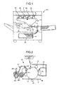
- Fig. 1 is a schematic diagram of a printer 100 as an image forming apparatus according to an embodiment of the present invention.
- the printer 100 includes an intermediate transfer belt device 15 arranged in the center of the printer 100.
- the printer 100 further includes image forming units 6Y, 6M, 6C, and 6K that corresponds respectively to colors of yellow (Y), magenta (M), cyan (C), and black (K).
- the image forming units 6Y, 6M, 6C, and 6K are arrange in parallel and opposed to an intermediate transfer belt 8 of the intermediate transfer belt device 15.
- the image forming units 6Y, 6M, 6C, and 6K are of basically the same configuration except that they form an image with toner of different colors, and thus but one of them, for example, the image forming unit 6Y is explained below.
- Fig. 2 is a schematic diagram of the image forming unit 6Y.
- the image forming unit 6Y includes a photosensitive drum 1Y, and further includes a charging unit 4Y, a developing unit 5Y, a cleaning unit 2Y, and a neutralizing unit (not shown) that are arranged around the photosensitive drum 1Y.
- An image forming process including a charging step, an exposing step, a developing step, and a transferring step is performed on the photosensitive drum 1Y to form a Y-image on a surface thereof.
- the photosensitive drum 1Y is rotated by a drive motor (not shown) clockwise as indicated by an arrow shown in Fig. 2 .
- the surface of the photosensitive drum 1Y is uniformly charged by the charging unit 4Y (charging step).
- the photosensitive drum 1Y rotates such that its surface is irradiated with a laser light L emitted by an exposing unit 7 based on image data.
- the laser light L forms a Y-electrostatic latent image on the surface of the photosensitive drum 1Y (exposing step).
- the Y-electrostatic latent image on the surface of the photosensitive drum 1Y is developed by the developing unit 5Y into a Y-toner image (developing step).
- the photosensitive drum 1Y rotates such that the Y-toner image reaches a position where the intermediate transfer belt 8 faces a transfer roller 9Y, and the Y-toner image is transferred onto the intermediate transfer belt 8 (a primary transfer step).
- toner resides on the surface of the photosensitive drum 1Y (hereinafter, "residual toner").
- the residual toner is removed from the surface of the photosensitive drum 1Y by a cleaning blade 2a of the cleaning unit 2Y and collected in the cleaning unit 2Y (cleaning step).
- the neutralizing unit neutralizes residual electric potential on the surface of the photosensitive drum 1Y.
- the image forming process is completed.
- the image forming process is performed by the image forming units 6M, 6C, and 6K in the same manner as above. Specifically, the laser light L emitted from the exposing unit 7 is deflected by a rotating polygon mirror to the photosensitive drums 1M, 1C, and 1K via a plurality of optical elements. Thus, the photosensitive drums 1M, 1C, and 1K are exposed with the laser light L and M, C, and K-electrostatic latent images are formed thereon, respectively.
- the Y, M, C, and K toner images formed on the photosensitive drums 1Y, 1M, 1C, and 1K by the developing step are transferred onto the intermediate transfer belt 8 in a superimposed manner, so that a superimposed color image is formed on the intermediate transfer belt 8.
- the intermediate transfer belt device 15 includes the intermediate transfer belt 8, transfer rollers 9Y, 9M, 9C and 9K, a drive roller 12A, support rollers 12B and 12C, a correcting roller 13, a movable roller 11, a roller member 14, a detecting unit 80, a photosensor 90, and a cleaning unit 10.
- the intermediate transfer belt 8 is supported by and stretched over the movable roller 11, the drive roller 12A, the support rollers 12B and 12C, and the correcting roller 13. Because of the rotation of a roller (the drive roller 12A), the intermediate transfer belt 8 rotates (endlessly moves) in the direction indicated by an arrow shown in Fig. 3 .
- the transfer rollers 9Y, 9M, 9C, and 9K and the photosensitive drums 1Y, 1M, 1C, and 1K form primary transfer nips between which is interposed the intermediate transfer belt 8.
- a voltage i.e., a transfer bias
- a transfer bias having a polarity opposite to that of the toner is applied to the transfer rollers 9Y, 9M, 9C, and 9K.
- the intermediate transfer belt 8 passes through the primary transfer nips, so that the Y, M, C, and K-toner images on the photosensitive drums 1Y, 1M, 1C, and 1K are sequentially transferred onto the intermediate transfer belt 8 in a superimposed manner (primary transfer step).
- the intermediate transfer belt 8 rotates such that the surface having a superimposed toner image of the Y, M, C, and K-toner images faces a secondary transfer roller 19.
- the support roller 12B and the secondary transfer roller 19 form a secondary transfer nip between which is interposed the intermediate transfer belt 8.
- the superimposed toner image is transferred onto a sheet (recording medium) P that is conveyed to the secondary transfer nip (secondary transfer step).
- the surface of the intermediate transfer belt 8 has residual toner.
- the cleaning unit 10 removes the residual toner from the surface of the intermediate transfer belt 8.
- the sheet P is fed from a sheet cassette 26, which is positioned in a lower portion of the printer 100 as shown in Fig. 1 (or on a side-wall side), and conveyed to the second transfer nip via, for example, a sheet feeding roller 27 and a pair of registration rollers 28.
- a stack of the sheets P are stored in the sheet cassette 26.
- the sheet feeding roller 27 is rotated counterclockwise, the top sheet P is fed from the sheet cassette 26 to the registration rollers 28.
- the sheet P temporarily stops at a roller nip between the registration rollers 28 having stopped rotating.
- the registration rollers 28 restart rotating at a specific timing to convey the sheet P to the secondary transfer nip.
- the superimposed toner image on the intermediate transfer belt 8 is transferred onto the sheet P at the secondary transfer nip, so that a desired color image is formed on the sheet P.
- the sheet P is conveyed to a fixing unit 20, and the color image is fixed onto the sheet P by heat and pressure by a fixing roller and a pressurizing roller of the fixing unit 20.
- the sheet P is discharged as an output image by a pair of discharging rollers (not shown) to the outside of the printer 100 on a stacker on which the sheets P are sequentially stacked.
- a pair of discharging rollers not shown
- the developing unit 5Y includes a developing roller 51Y opposed to the photosensitive drum 1Y, a doctor blade 52Y, two transfer screws 55Y in a developer container, a toner supplying path 43Y that communicates with the developer container, and a toner concentration sensor 56Y that detects concentration of toner in a developer (hereinafter, "toner concentration").
- the developing roller 51Y includes a magnet and a sleeve that surrounds the magnet.
- the developer container is partitioned into two compartments, and contains a developer containing toner and carrier.
- the sleeve of the developing roller 51Y rotates in a direction indicated by an arrow shown in Fig. 2 .
- the developer is lifted up to the developing roller 51Y by a magnetic force of the magnet of the developing roller 51Y, and moves on the developing roller 51Y along with the rotation of the sleeve.
- the ratio of toner in the developer i.e., toner concentration, is adjusted to be within a predetermined range.
- the developer is circulated in the developer container while being mixed and stirred by the transfer screws 55Y.
- the toner in the developer adheres to the carrier because of triboelectric charging between the toner and the carrier, and the toner adheres to the developing roller 51Y together with the carrier by the magnetic force generated on the surface of the developing roller 51Y.
- the developer on the surface of the developing roller 51Y is conveyed in a direction indicated by an arrow shown in Fig. 2 to the doctor blade 52Y, and the doctor blade 52Y adjusts the amount of the developer on the surface of the developing roller 51Y. Thereafter, the developer is conveyed to a position opposed to the photosensitive drum 1Y (hereinafter, "developing area"). Because of a magnetic field formed in the developing area, the toner adheres to the electrostatic latent image on the photosensitive drum 1Y. The developer residing on the developing roller 51Y reaches an upper space of the developer container along with the rotation of the sleeve and separates from the developing roller 51Y.
- the intermediate transfer belt device 15 is explained in detail with reference to Figs. 3 to 5 .
- Fig. 3 is a schematic diagram of the intermediate transfer belt device 15.
- Fig. 4 is a top view of part of the intermediate transfer belt device 15.
- Fig. 5 is a perspective view of part of the intermediate transfer belt device 15.
- the intermediate transfer belt device 15 further includes an error sensor 88.
- the intermediate transfer belt 8 is opposed to the photosensitive drums 1Y, 1M, 1C, and 1K.
- the intermediate transfer belt 8 of the first embodiment is formed of a layer or a plurality of layers made of polyvinylidene difluoride (PVDF), ethylen-tetrafluorethylen-copolymer (ETFE), polyimide (PI), or polycarbonate (PC), in which a conductive material such as carbon black is dispersed.
- PVDF polyvinylidene difluoride
- ETFE ethylen-tetrafluorethylen-copolymer
- PI polyimide
- PC polycarbonate
- a volume resistivity of the intermediate transfer belt 8 is adjusted to be within a range from 10 7 Ocm to 10 12 Ocm and the surface resistivity of the back surface of the intermediate transfer belt 8 is adjusted to be within a range from 10 8 Ocm to 10 12 Ocm.
- the thickness of the intermediate transfer belt 8 is within a range from 80 micrometers to 100 micrometers. Specifically, in the first embodiment, the intermediate transfer belt 8
- the surface of the intermediate transfer belt 8 can be coated with a release layer.
- material of the release layer include, but are not limited to, fluororesin such as ETFE, polytetrafluoroethylene (PTFE), PVDF, fluorinated ethylene propylene (PVDF), polyfluoroalkoxy (PFA), tetrafluoroethylene-co-hexafluoropropylene (FEP), or polyvinyl fluoride (PVF).
- fluororesin such as ETFE, polytetrafluoroethylene (PTFE), PVDF, fluorinated ethylene propylene (PVDF), polyfluoroalkoxy (PFA), tetrafluoroethylene-co-hexafluoropropylene (FEP), or polyvinyl fluoride (PVF).
- the intermediate transfer belt 8 is manufactured by, for example, casting or a centrifugal method.
- the surface of the intermediate transfer belt 8 is polished if necessary.
- the transfer rollers 9Y, 9M, 9C, and 9K are opposed to the photosensitive drums 1Y, 1M, 1C, and 1K with the intermediate transfer belt 8 interposed therebetween.
- the transfer roller 9Y is opposed to the photosensitive drum 1Y with the intermediate transfer belt 8 interposed therebetween
- the transfer roller 9M is opposed to the photosensitive drum 1M with the intermediate transfer belt 8 interposed therebetween
- the transfer roller 9C is opposed to the photosensitive drum 1C with the intermediate transfer belt 8 interposed therebetween
- the transfer roller 9K is opposed to the photosensitive drum 1K with the intermediate transfer belt 8 interposed therebetween.
- the movable roller 11 is supported by a support member (not shown) together with the transfer rollers 9Y, 9M, 9C, and 9K and is capable of separating the intermediate transfer belt 8 from the photosensitive drums 1Y, 1M, 1C, and 1K.
- the transfer rollers 9Y, 9M. 9C, and 9K move lower as well.
- the intermediate transfer belt 8 separates from the photosensitive drums 1Y, 1M, 1C, and 1K as indicated by a dotted line shown in Fig. 3 .
- the intermediate transfer belt 8 is separated from the photosensitive drums 1Y, 1M, 1C, and 1K to reduce abrasion of the intermediate transfer belt 8.
- the drive roller 12A is rotated by a drive motor (not shown) to rotate the intermediate transfer belt 8 in a predetermined direction (clockwise in Fig. 3 ).
- the support roller 12B forms a nip with the secondary transfer roller 19 with the intermediate transfer belt 8 interposed therebetween.
- the support roller 12C is in contact with an outer circumference (front surface) of the intermediate transfer belt 8.
- the cleaning unit 10 cleaning blade is arranged between the support rollers 12B and 12C.
- the detecting unit 80 detects deviation of the intermediate transfer belt 8 in a direction of the width of the intermediate transfer belt 8 (hereinafter, "belt width direction").
- the detecting unit 80 is explained in detail below with reference to Fig. 5 .
- the detecting unit 80 includes a swaying member 82 that is in contact with an edge of the intermediate transfer belt 8 in the belt width direction, a distance sensor 81 that detects the amount of swaying of the swaying member 82, and a spring 83 that biases the swaying member 82 toward the intermediate transfer belt 8.
- the swaying member 82 includes a first arm member 82a, a rotation shaft 82b, and a second arm member 82c.
- a first end portion of the first arm member 82a is in contact with the edge of the intermediate transfer belt 8, and a second end portion of the first arm member 82a, which is on an side opposite to that of the first end portion, is fixed to the rotation shaft 82b.
- the rotation shaft 82b is rotatably supported by a chassis (not shown) of the intermediate transfer belt device 15.
- a first end portion of the second arm member 82c is fixed to the rotation shaft 82b.
- a first end of the spring 83 is fixed to a center portion of the second arm member 82c.
- a second end of the spring 83 is connected to the chassis.
- the swaying member 82 sways with the deviation of the intermediate transfer belt 8 in the belt width direction indicated by a dotted arrow shown in Fig. 5 .
- the intermediate transfer belt 8 rotates, for example, at a speed of 400 mm/sec in a direction indicated by an arrow shown in Fig. 5 (hereinafter, "belt rotation direction")
- the distance sensor 81 is fixed to the chassis above a second end portion of the second arm member 82c, which is on a side opposite to that of the first end portion of the second arm member 82c.
- the distance sensor 81 includes a position sensitive detector (PSD) and a plurality of light emitting elements (infrared-emitting diodes) arranged horizontally in parallel with a specific spacing. An infrared light emitted from the light emitting element is reflected on a surface of the second arm unit 82c and is incident on the PSD as a reflected light. A position where the reflected light is incident on the PSD (hereinafter, "incident position”) changes depending on a distance between the distance sensor 81 and the surface of the second arm member 82c.
- PSD position sensitive detector
- the value of an output of the distance sensor 81 changes in proportion to the change in the incident position. Because of this, the deviation of the intermediate transfer belt 8 in the belt width direction can be detected. Specifically, when the distance detected by the distance sensor 81 is smaller than a predetermined value, the intermediate transfer belt 8 deviates to a right side shown in Fig. 5 in the belt width direction from a target position where the intermediate transfer belt 8 is supposed to be positioned. On the other hand, when the distance detected by the distance sensor 81 is larger than a predetermined value, the intermediate transfer belt 8 deviates to a left side in the belt width direction from the target position.
- the roller member 14 is arranged near the detecting unit 80.
- the roller member 14 prevents the deviation of the intermediate transfer belt 8 in a direction other than the belt width direction and the belt rotation direction.
- the roller member 14 is arranged in a position on an upstream side in the belt rotation direction of the position where the swaying member 82 (the first arm member 82a) and the intermediate transfer belt 8 are in contact with each other.
- the above structure reduces the deviation of the intermediate transfer belt 8 in the direction perpendicular to the belt width direction at the detecting unit 80 (i.e., at the position where the swaying member 82 and the intermediate transfer belt 8 are in contact with each other.
- the roller member 14 increase the tensile force of the intermediate transfer belt 8, which prevents the deviation of the of the intermediate transfer belt 8 in the direction perpendicular to the belt width direction at the detecting unit 80.
- accuracy increases in the detection of the deviation of the intermediate transfer belt 8 by the detecting unit 80.
- the roller member 14 that rotates along with the rotation of the intermediate transfer belt 8 is used to prevent the deviation of the intermediate transfer belt 8 in the direction perpendicular to the belt width direction.
- damage to the inner circumference (back surface) of the intermediate transfer belt 8 can be reduced with a relatively simple configuration.
- the correcting roller 13 corrects the deviation of the intermediate transfer belt 8.
- the correcting roller 13 is positioned on an upstream side of the photosensitive drums 1Y, 1M, 1C, and 1K in the belt rotation direction and is in contact with the back surface of the intermediate transfer belt 8.
- the correcting roller 13 is configured to move in directions indicated by arrows X1 and X2 shown in Fig. 4 (hereinafter, "X1 direction” and "X2 direction") when a drive cam (not shown) moves by a predetermined angle.
- the correcting roller 13 moves in the X2 direction based on the detection by the detecting unit 80 to correct the deviation. In this manner, the intermediate transfer belt 8 is prevented from rotating while twisted or from deviating to the extent that it is in contact with another member and thus is damaged.
- the detecting unit 80 and the roller member 14 are distant from the correcting roller 13. Specifically, while the correcting roller 13 is positioned on the upstream side of the photosensitive drums 1Y, 1M, 1C, and 1K in the belt rotation direction, the detecting unit 80 and the roller member 14 are positioned on a downstream side of the photosensitive drums 1Y, 1M, 1C, and 1K in the belt rotation direction.
- the error sensors 88 are arranged on both sides of the intermediate transfer belt 8 in the belt width direction, and are about 5 millimeters distant from the edges of the intermediate transfer belt 8 in the belt width direction.
- An error sensor 88 includes an arm member that is in contact with the intermediate transfer belt 8 when the intermediate transfer belt 8 largely deviates, an optical sensor that optically detects movement of the arm member on a rotation axis, which is caused because the intermediate transfer belt 8 is in contact with the arm member.
- the error sensor 88 is configured to detect an error, i.e., the deviation of the intermediate transfer belt 8 which cannot be corrected by the correcting roller 13.
- an error i.e., the deviation of the intermediate transfer belt 8 which cannot be corrected by the correcting roller 13.
- the driving of the intermediate transfer belt 8 by the drive roller 12A is terminated, and a display unit of the printer 100 displays an error message such as those notifying a user that fixation by a service engineer is required.
- the detecting unit 80 and the roller member 14 are distant from an area where the intermediate transfer belt 8 is opposed to the photosensitive drums 1Y, 1M, 1C, and 1K. Specifically, the detecting unit 80 and the roller member 14 are positioned on a downstream side in the belt rotation direction of the area where the intermediate transfer belt 8 is opposed to the photosensitive drums 1Y, 1M, 1C, and 1K.
- the intermediate transfer belt device 15 can be downsized and the mechanism for separating the intermediate transfer belt 8 from the photosensitive drums 1Y, 1M, 1C, and 1K can be simplified. Moreover, efficiency of maintenance of the detecting unit 80 improves and an erroneous operation of the detecting unit 80, which is caused by noise due to a high-voltage power source (not shown) provided near the image forming units 6Y, 6M, 6C, and 6K, can be prevented.
- the photosensor 90 is positioned near the roller member 14.
- the photosensor 90 detects the position and toner concentration of the toner image (patch pattern) on the intermediate transfer belt 8 to optimize the environment in which an image is formed.
- the photosensor 90 optically detects the shifting of the toner image formed on the intermediate transfer belt 8 via the image forming process explained above. Based on the result of the detection of the shifting of the toner image, the timing of exposing the photosensitive drums 1Y, 1M, 1C, and 1K by the exposing unit 7 is adjusted.
- the photosensor 90 detects the toner concentration of the toner image on the intermediate transfer belt 8. Based on the result of the detection of the toner concentration, the toner concentration of the developer stored in the developing unit 5Y is adjusted.
- Arranging the photosensor 90 near the roller member 14 reduces a possibility that the photosensor 90 detects the intermediate transfer belt 8 with the surface waving. Because the distance between the photosensor 90 and the toner image is kept stable, the photosensor 90 can detect the position and toner concentration of the toner image with high accuracy.
- the roller member 14 is arranged near the detecting unit 80, the deviation of the intermediate transfer belt 8 in the belt width direction can be accurately detected with a simple configuration even if the image forming performs high speed printing.
- the roller member 14 that is in contact with the back surface of the intermediate transfer belt 8 is used as the preventing unit.
- a pair of roller members that are respectively in contact with the front and back surfaces of the intermediate transfer belt 8 can be arranged as the preventing unit. Also with such roller members, deviation of the intermediate transfer belt 8 in the direction perpendicular to the belt width direction can be prevented near the detecting unit 80. Thus, the same effects as those obtained with the roller member 14 can be achieved.
- the intermediate transfer belt device 15 including the intermediate transfer belt 8 is used as a belt device.
- a belt device including a transfer-conveying belt can be used.
- a belt device including a photosensitive endless belt that has same functions as those of the photosensitive drums 1Y, 1M, 1C, and 1K of the first embodiment can be alternatively used.
- a preventing unit that prevents deviation of a belt member in a direction perpendicular to a belt width direction of the belt member, the same effects as those obtained in the first embodiment can be achieved.
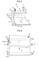
- the intermediate transfer belt device of the second embodiment includes a detecting unit 180 that detects deviation of the intermediate transfer belt 8 in the belt width direction.
- the detecting unit 180 includes a swaying member 182 that is in contact with the edge of the intermediate transfer belt 8 in the belt width direction, the distance sensor 81 that detects the amount of swaying of the swaying member 182, and the spring 83 that biases the swaying member 182 to the intermediate transfer belt 8.
- the swaying member 182 includes the first arm member 82a, the rotation shaft 82b, and the second arm member 82c.
- the swaying member 182 further includes a cylindrical member 82a1 that is provided to the first arm member 82a, and that is in contact with the edge of the intermediate transfer belt 8.
- the second end portion of the first arm member 82a is fixed to the rotation shaft 82b.
- the rotation shaft 82b is rotatably supported by the chassis (not shown) of the intermediate transfer belt device.
- the first end portion of the second arm member 82c is fixed to the rotation shaft 82b.
- the first end of the spring 83 is fixed to the center portion of the second arm member 82c.
- the second end of the spring 83 is connected to the chassis.
- the swaying member 182 sways with the deviation of the intermediate transfer belt 8 in the belt width direction indicated by an arrow of a dotted line shown in Fig. 7 .
- the distance sensor 81 is fixed to the chassis above a second end portion of the second arm member 82c.
- the distance sensor 81 includes the PSD and the light emitting elements (infrared-emitting diodes) arranged in parallel with a specific interval.
- An infrared light emitted from the light emitting element is reflected on the surface of the second arm unit 82c and is incident on the PSD as a reflected light.
- a position where the reflected light is incident on the PSD (hereinafter, "incident position") changes depending on a distance between the distance sensor 81 and the surface of the second arm member 82c.
- the value of an output of the distance sensor 81 changes in proportion to the incident position.
- the deviation of the intermediate transfer belt 8 in the belt width direction can be detected. Specifically, when the distance detected by the distance sensor 81 is smaller than a predetermined value, the intermediate transfer belt 8 deviates to a right side shown in Fig. 5 in the belt width direction from a target position where the intermediate transfer belt 8 should be positioned. On the other hand, when the distance detected by the distance sensor 81 is larger than a predetermined value, the intermediate transfer belt 8 deviates to a left side from the target position in the belt width direction.
- the intermediate transfer belt 8 of the second embodiment rotates at a speed of 400 mm/sec in a direction indicated by an arrow shown in Fig. 7 (hereinafter, "belt rotation direction").
- a biasing force of the spring 83 is such that the intermediate transfer belt 8 does not deform due to the swaying member 182 being in contact with the intermediate transfer belt 8 (hereinafter, "contact force") while the swaying member 182 is pressed against the intermediate transfer belt 8 without vibrating even with the deviation (chattering) of the intermediate transfer belt 8 in the belt width direction.
- the contact force of a contact portion (the cylindrical member 82a1) of the swaying member 182 is about 70 grams in the second embodiment.
- the cylindrical member 82a1 having a curved surface serves as the contact portion.
- the swaying member 182 has linear contact (or point contact from a macroscopic point of view) with the intermediate transfer belt 8 (i.e., the cylindrical member 82a1 is in contact with the intermediate transfer belt 8 in a small area). Thus, even if the intermediate transfer belt 8 deviates in the direction perpendicular to the belt width direction, the swaying member 182 tends not to sway due to the deviation of the intermediate transfer belt 8.
- the result of detecting the deviation of the intermediate transfer belt 8 in the belt width direction by the distance sensor 81 tends not to vary. Furthermore, the abrasion of the swaying member 182 (the cylindrical member 82a1) and the intermediate transfer belt 8, which is caused because the swaying member 182 and the intermediate transfer belt 8 move while being in contact with each other, is reduced. Thus, it is possible to detect the deviation of the intermediate transfer belt 8 in the belt width direction with high accuracy over time.
- the cylindrical member 82a1 is made of a metal material such as stainless in the second embodiment, the abrasion of the cylindrical member 82a1, which is caused because the cylindrical member 82a1 move while being in contact with each other, tends not to occur. Thus, chronological change in the result of the detection by the distance sensor 81 can be reduced. It is particularly preferable that the cylindrical member 82a1 has a smooth surface with a low coefficient of friction.
- the cylindrical member 82a1 is rotated by the rotation of the intermediate transfer belt 8 in the direction indicated by an arrow shown in Fig. 7 .
- a rotation shaft of the cylindrical member 82a1 is supported by the first arm member 82a.
- the roller member 14 is arranged near the detecting unit 180.
- the roller member 14 prevents the deviation of the intermediate transfer belt 8 in the direction other than the belt width direction and the belt rotation direction.
- the roller member 14 is positioned near the contact portion (i.e., the cylindrical member 82a1) between the swaying member 182 (the first arm member 82a) and the intermediate transfer belt 8.
- the above structure reduces the deviation of the intermediate transfer belt 8 in the direction perpendicular to the belt width direction at the detecting unit 180 (the cylindrical member 82a1). Specifically, the roller member 14 increases the tensile force of the intermediate transfer belt 8, which prevents the deviation of the intermediate transfer belt 8 in the direction perpendicular to the belt width direction at the detecting unit 180. This reduces a possibility that the detecting unit 180 detects a deviation component in a direction other than the belt width direction and the belt rotation direction in addition to a deviation component in the belt width direction. Thus, accuracy increases in the detection of the deviation of the intermediate transfer belt 8 by the detecting unit 180.
- the correcting roller 13 Based on a result of the detection of the deviation of the intermediate transfer belt 8 in the belt width direction by the detecting unit 80, the correcting roller 13 corrects the deviation of the intermediate transfer belt 8.
- the correcting roller 13 is positioned on an upstream side of the photosensitive drums 1Y, 1M, 1C, and 1K in the belt rotation direction and is in contact with the back surface of the intermediate transfer belt 8.
- the correcting roller 13 is configured to move in directions indicated by arrows X1 and X2 shown in Fig. 6 (hereinafter, "X1 direction” and "X2 direction”) on the moving axis 13a when the drive cam (not shown) moves by a predetermined angle.
- the correcting roller 13 moves in the X2 direction based on a result of the detection by the detecting unit 180, so that the deviation is corrected. In this manner, the intermediate transfer belt 8 is prevented from twisting or from deviating in the belt width direction to the extent that it is in contact with another member and thus is damaged.
- the detecting unit 180 is distant from the correcting roller 13. Specifically, while the correcting roller 13 is positioned on an upstream side of an area where the intermediate transfer belt 8 is opposed to the photosensitive drums 1Y, 1M, 1C, and 1K (hereinafter, "opposition area") in the belt rotation direction, the detecting unit 80 is positioned on a downstream side of the opposition area in the belt rotation direction.
- the detecting unit 180 can detect the deviation in the belt width direction with high accuracy.
- the error sensors 88 are arranged on both sides of the intermediate transfer belt 8 in the belt width direction, and are about 5 millimeters distant from the edges of the intermediate transfer belt 8 in the belt width direction.
- the error sensor 88 includes the arm member that is in contact with the intermediate transfer belt 8 when the intermediate transfer belt 8 largely deviates, the optical sensor that optically detects rotation (movement) of the arm member on its rotation shaft, which is caused because the intermediate transfer belt 8 is in contact with the arm member.
- the error sensor 88 detects the deviation of the intermediate transfer belt 8, which cannot be corrected by the correcting roller 13 (i.e., the error sensor 88 detects an error).
- the error sensor 88 detects an error, the driving of the intermediate transfer belt 8 by the drive roller 12A is terminated, and a message prompting fixing is displayed on a display unit of the printer 100.
- the detecting unit 180 is distant from the opposition area as explained above. Specifically, the detecting unit 180 and the roller member 14 are positioned on the downstream side of the opposition area in the belt rotation direction (where a primary transfer step is performed).
- the intermediate transfer belt device 15 can be downsized and the system for separating the intermediate transfer belt 8 from the photosensitive drums 1Y, 1M, 1C, and 1K can be simplified. Moreover, efficiency of maintenance of the detecting unit 180 improves and an erroneous operation of the detecting unit 180, which is caused by noise due to the high-voltage power source (not shown) provided near the image forming units 6Y, 6M, 6C, and 6K, can be prevented.
- the photosensor 90 is positioned near the roller member 14 as shown in Figs. 3 and 6 .
- the photosensor 90 detects the position and toner concentration of a toner image (patch pattern) on the intermediate transfer belt 8 to optimize the environment in which an image is formed.
- the photosensor 90 optically detects the shifting of the toner image formed on the intermediate transfer belt 8 via the image forming process explained above. Based on the result of the detection of the shifting of the toner image, the timing of exposing the photosensitive drums 1Y, 1M, 1C, and 1K by the exposing unit 7 is adjusted.
- the photosensor 90 optically detects the toner concentration of the toner image on the intermediate transfer belt 8. Based on the result of the detection of the toner concentration, the toner concentration of the developer stored in the developing unit 5 is adjusted.
- Arranging the photosensor 90 near the roller member 14 reduces a possibility that the photosensor 90 detects the deviation of the intermediate transfer belt 8 with the waving surface. Because the distance between the photosensor 90 and the toner image is kept constant, the photosensor 90 can detect the position and toner concentration of the toner image with high accuracy.
- the swaying member 182 has the linear contact with the intermediate transfer belt 8 (i.e., the swaying member 182 is in contact with the intermediate transfer belt 8 in a small area).
- the deviation of the intermediate transfer belt 8 in the belt width direction can be detected with high accuracy over time with a relatively simple configuration.
- FIG. 8 is a perspective view of the detecting unit 280.
- the detecting unit 280 includes a swaying member 282, the distance sensor 81, and the spring 83.
- the swaying member 282 includes a curved member 82a2 that has a curved surface and that is integrally formed with the first arm member 82a.
- the curved member 82a2 serves as a contact portion that is in contact with the edge of the intermediate transfer belt 8 in the belt width direction.
- the swaying member 282 has linear contact (or point contact from a macroscopic point of view) with the intermediate transfer belt 8 (i.e., the curved member 82a2 is in contact with the intermediate transfer belt 8 in a small area).
- deviation of the intermediate transfer belt 8 in the belt width direction can be detected with high accuracy.
- the curved member 82a2 be formed of a metal material and have a smooth surface with a low coefficient of friction.
- the metal material and the smooth surface improve durability of the swaying member 282 and reduce the possibility that the accuracy in the detection by the distance sensor 81 gradually decreases over time.
- the swaying member 282 has linear contact with the intermediate transfer belt 8 (i.e., the curved member 82a2 is in contact with the intermediate transfer belt in a small area).
- the deviation of the intermediate transfer belt 8 in the belt width direction can be detected with high accuracy over time with a relatively simple configuration.
- an intermediate transfer belt is cited as an example of a belt member deviation of which is detected.
- the belt member can be a transfer-conveying belt that conveys a recording medium onto which are transferred toner images of different colors to form a color image thereon.
- the belt member can also be a photosensitive endless belt that has the same function as the photosensitive drums 1Y, 1M, 1C, and 1K described in the first embodiment. In these cases also, by providing a contact portion of a swaying member with a curved surface that is in contact with the belt member, the same effects as those obtained in the above embodiments can be achieved.
- deviation of a belt member in the belt width direction can be detected with high accuracy over a period of time with a simple configuration.
Landscapes
- Physics & Mathematics (AREA)
- General Physics & Mathematics (AREA)
- Electrostatic Charge, Transfer And Separation In Electrography (AREA)
Abstract
Description
- The present application claims priority to and incorporates by reference the entire contents of Japanese priority documents,
2007-086363 filed in Japan on March 29, 2007 2007-086467 filed in Japan on March 29, 2007 - The present invention relates to a belt device, a belt deviation detecting device, and an image forming apparatus.
- Among image forming apparatuses such as copiers and printers is known a tandem color image forming apparatus including an intermediate transfer belt (belt member) as disclosed in, for example, Japanese Patent Application Laid-open Nos.
2006-343629 2001-83840 - A tandem color image forming apparatus includes an intermediate transfer belt and four photosensitive drums (image carriers) that are opposed to the intermediate transfer belt. Black (K), yellow (Y), magenta (M), and cyan (C) toner images are formed on the photosensitive drums, respectively. The K, Y, M, and C toner images are transferred onto the intermediate transfer belt in a superimposed manner to obtain a superimposed toner image. The superimposed toner image on the intermediate transfer belt is then transferred as a color image onto a recording medium.
- For example, Japanese Patent Application Laid-open Nos.
2006-343629 2001-83840 - Specifically, the conventional image forming apparatus disclosed in Japanese Patent Application Laid-open No.
2006-343629 - The above conventional image forming apparatus cannot accurately detect deviation of the belt member in the belt width direction when the belt member deviates in a direction perpendicular to the belt width direction that is not a direction in which the belt member rotates (moves) (hereinafter, "belt rotation direction"). In other words, in addition to a deviation component in the belt width direction that is supposed to be detected, the detecting unit sometimes detects a deviation component in a direction other than the belt width direction and the belt rotation direction. This decreases the accuracy in correcting the deviation of the belt member based on the result of the detection by the detecting unit.
- The belt member deviates in the direction other than the belt width direction and the belt rotation direction because the belt member supported by and stretched over a plurality of rollers moves while waving in the direction perpendicular to the belt width direction. Such waving of the belt member frequently occurs particularly in a high-speed image forming apparatus in which a belt member moves at high speed (i.e., an image forming apparatus having a high process linear speed).
- The belt member is not limited to an intermediate transfer belt and can be a transfer-conveyer belt or a photosensitive belt deviation of which is detected and corrected.
- In addition, in the conventional image forming apparatus, the deviation of the belt member in the belt width direction may not be detected with high accuracy.
- Specifically, the belt member of the conventional image forming apparatus is in contact with the swaying member with a large area. Thus, when the belt member deviates (twists) in the direction perpendicular to the belt width direction (not the belt rotation direction but the vertical direction), the swaying member may sway along with the deviation in the vertical direction, which may results in inaccurate detection of the deviation of the belt member in the belt width direction. Moreover, variation in accuracy in attaching the swaying member to the belt member (an angle at which the swaying member is attached to the belt member) tends to cause variation in the result of detecting the deviation of the belt member in the belt width direction. Furthermore, the swaying member and the belt member are frayed or worn after moving for a long period while in contact with each other. This leads to a chronological change in the result of detection of the deviation of the belt member in the belt width direction.
- The above inconveniences cannot be ignored especially in a high-speed image forming apparatus.
- It is an object of the present invention to at least partially solve the problems in the conventional technology.
- According to an aspect of the present invention, there is provided a belt device including a belt member that is stretched over a plurality of rollers and moves in a predetermined moving direction; a detecting unit that detects deviation of the belt member in a belt width direction of the belt member; and a preventing member that is arranged near the detecting unit, and that prevents deviation of the belt member in a direction other than the moving direction and the belt width direction.
- According to another aspect of the present invention, there is provided a belt deviation detecting device that detects deviation of a belt member in a belt width direction of the belt member, which moves in a predetermined direction. The belt deviation detecting device includes a swaying member that sways along with the deviation of the belt member in the belt width direction, and includes a contact portion that is in contact with an edge of the belt member in the belt width direction; and a detecting unit that detects an amount of swaying of the swaying member. The contact portion has a curved surface.
- According to still another aspect of the present invention, there is provided an image forming apparatus including a belt device that includes a belt member that is stretched over a plurality of rollers and moves in a predetermined moving direction; a detecting unit that detects deviation of the belt member in a belt width direction of the belt member; and a preventing member that is arranged near the detecting unit, and that prevents deviation of the belt member in a direction other than the moving direction and the belt width direction.
- The above and other objects, features, advantages and technical and industrial significance of this invention will be better understood by reading the following detailed description of presently preferred embodiments of the invention, when considered in connection with the accompanying drawings.
-
-
Fig. 1 is a schematic diagram of an image forming apparatus according a first embodiment of the present invention; -
Fig. 2 is a schematic diagram of an image forming unit shown inFig.1 ; -
Fig. 3 is a schematic diagram of a belt device shown inFig. 1 ; -
Fig. 4 is a top view of an example of part of a belt member of the belt device; -
Fig. 5 is a perspective view of a detecting unit shown inFig. 3 ; -
Fig. 6 is a top view of another example of part of a belt member of the belt device; -
Fig. 7 is a perspective view of a detecting unit according to a second embodiment of the present invention; and -
Fig. 8 is a perspective view of a modification of the detecting unit shown inFig. 7 . - Exemplary embodiments of the present invention are explained in detail below with reference to the accompanying drawings. Like reference characters refer to corresponding portions throughout the drawings.
-
Fig. 1 is a schematic diagram of aprinter 100 as an image forming apparatus according to an embodiment of the present invention. Theprinter 100 includes an intermediatetransfer belt device 15 arranged in the center of theprinter 100. Theprinter 100 further includesimage forming units image forming units intermediate transfer belt 8 of the intermediatetransfer belt device 15. - The
image forming units image forming unit 6Y is explained below. -
Fig. 2 is a schematic diagram of theimage forming unit 6Y. Theimage forming unit 6Y includes aphotosensitive drum 1Y, and further includes acharging unit 4Y, a developingunit 5Y, acleaning unit 2Y, and a neutralizing unit (not shown) that are arranged around thephotosensitive drum 1Y. An image forming process including a charging step, an exposing step, a developing step, and a transferring step is performed on thephotosensitive drum 1Y to form a Y-image on a surface thereof. - The
photosensitive drum 1Y is rotated by a drive motor (not shown) clockwise as indicated by an arrow shown inFig. 2 . The surface of thephotosensitive drum 1Y is uniformly charged by thecharging unit 4Y (charging step). - The
photosensitive drum 1Y rotates such that its surface is irradiated with a laser light L emitted by anexposing unit 7 based on image data. The laser light L forms a Y-electrostatic latent image on the surface of thephotosensitive drum 1Y (exposing step). - The Y-electrostatic latent image on the surface of the
photosensitive drum 1Y is developed by the developingunit 5Y into a Y-toner image (developing step). - The
photosensitive drum 1Y rotates such that the Y-toner image reaches a position where theintermediate transfer belt 8 faces atransfer roller 9Y, and the Y-toner image is transferred onto the intermediate transfer belt 8 (a primary transfer step). At this stage, toner resides on the surface of thephotosensitive drum 1Y (hereinafter, "residual toner"). - The residual toner is removed from the surface of the
photosensitive drum 1Y by acleaning blade 2a of thecleaning unit 2Y and collected in thecleaning unit 2Y (cleaning step). - Thereafter, the neutralizing unit neutralizes residual electric potential on the surface of the
photosensitive drum 1Y. Thus, the image forming process is completed. - The image forming process is performed by the
image forming units unit 7 is deflected by a rotating polygon mirror to thephotosensitive drums photosensitive drums photosensitive drums intermediate transfer belt 8 in a superimposed manner, so that a superimposed color image is formed on theintermediate transfer belt 8. - As shown in
Fig. 3 , the intermediatetransfer belt device 15 includes theintermediate transfer belt 8,transfer rollers drive roller 12A,support rollers roller 13, amovable roller 11, aroller member 14, a detectingunit 80, aphotosensor 90, and acleaning unit 10. Theintermediate transfer belt 8 is supported by and stretched over themovable roller 11, thedrive roller 12A, thesupport rollers roller 13. Because of the rotation of a roller (thedrive roller 12A), theintermediate transfer belt 8 rotates (endlessly moves) in the direction indicated by an arrow shown inFig. 3 . - The
transfer rollers photosensitive drums intermediate transfer belt 8. A voltage (i.e., a transfer bias) having a polarity opposite to that of the toner is applied to thetransfer rollers - The
intermediate transfer belt 8 passes through the primary transfer nips, so that the Y, M, C, and K-toner images on thephotosensitive drums intermediate transfer belt 8 in a superimposed manner (primary transfer step). - Thereafter, the
intermediate transfer belt 8 rotates such that the surface having a superimposed toner image of the Y, M, C, and K-toner images faces asecondary transfer roller 19. At this position, thesupport roller 12B and thesecondary transfer roller 19 form a secondary transfer nip between which is interposed theintermediate transfer belt 8. The superimposed toner image is transferred onto a sheet (recording medium) P that is conveyed to the secondary transfer nip (secondary transfer step). At this stage, the surface of theintermediate transfer belt 8 has residual toner. - Thereafter, the
cleaning unit 10 removes the residual toner from the surface of theintermediate transfer belt 8. - In this manner, a transfer process performed on the
intermediate transfer belt 8 is completed. A configuration and operations of the intermediatetransfer belt device 15 are explained in detail below with reference toFigs. 3 to 5 . - The sheet P is fed from a
sheet cassette 26, which is positioned in a lower portion of theprinter 100 as shown inFig. 1 (or on a side-wall side), and conveyed to the second transfer nip via, for example, asheet feeding roller 27 and a pair ofregistration rollers 28. - Specifically, a stack of the sheets P are stored in the
sheet cassette 26. When thesheet feeding roller 27 is rotated counterclockwise, the top sheet P is fed from thesheet cassette 26 to theregistration rollers 28. - The sheet P temporarily stops at a roller nip between the
registration rollers 28 having stopped rotating. Theregistration rollers 28 restart rotating at a specific timing to convey the sheet P to the secondary transfer nip. The superimposed toner image on theintermediate transfer belt 8 is transferred onto the sheet P at the secondary transfer nip, so that a desired color image is formed on the sheet P. - Thereafter, the sheet P is conveyed to a fixing
unit 20, and the color image is fixed onto the sheet P by heat and pressure by a fixing roller and a pressurizing roller of the fixingunit 20. - Thereafter, the sheet P is discharged as an output image by a pair of discharging rollers (not shown) to the outside of the
printer 100 on a stacker on which the sheets P are sequentially stacked. Thus, the image forming process is completed. - A configuration and operations of the developing
unit 5Y are explained in detail below with reference toFig. 2 . - The developing
unit 5Y includes a developingroller 51Y opposed to thephotosensitive drum 1Y, adoctor blade 52Y, twotransfer screws 55Y in a developer container, atoner supplying path 43Y that communicates with the developer container, and atoner concentration sensor 56Y that detects concentration of toner in a developer (hereinafter, "toner concentration"). The developingroller 51Y includes a magnet and a sleeve that surrounds the magnet. The developer container is partitioned into two compartments, and contains a developer containing toner and carrier. - The sleeve of the developing
roller 51Y rotates in a direction indicated by an arrow shown inFig. 2 . The developer is lifted up to the developingroller 51Y by a magnetic force of the magnet of the developingroller 51Y, and moves on the developingroller 51Y along with the rotation of the sleeve. The ratio of toner in the developer, i.e., toner concentration, is adjusted to be within a predetermined range. - The developer is circulated in the developer container while being mixed and stirred by the transfer screws 55Y. The toner in the developer adheres to the carrier because of triboelectric charging between the toner and the carrier, and the toner adheres to the developing
roller 51Y together with the carrier by the magnetic force generated on the surface of the developingroller 51Y. - The developer on the surface of the developing
roller 51Y is conveyed in a direction indicated by an arrow shown inFig. 2 to thedoctor blade 52Y, and thedoctor blade 52Y adjusts the amount of the developer on the surface of the developingroller 51Y. Thereafter, the developer is conveyed to a position opposed to thephotosensitive drum 1Y (hereinafter, "developing area"). Because of a magnetic field formed in the developing area, the toner adheres to the electrostatic latent image on thephotosensitive drum 1Y. The developer residing on the developingroller 51Y reaches an upper space of the developer container along with the rotation of the sleeve and separates from the developingroller 51Y. - The intermediate
transfer belt device 15 is explained in detail with reference toFigs. 3 to 5 . -
Fig. 3 is a schematic diagram of the intermediatetransfer belt device 15.Fig. 4 is a top view of part of the intermediatetransfer belt device 15.Fig. 5 is a perspective view of part of the intermediatetransfer belt device 15. - As shown in
Fig. 4 , the intermediatetransfer belt device 15 further includes anerror sensor 88. Theintermediate transfer belt 8 is opposed to thephotosensitive drums - The
intermediate transfer belt 8 of the first embodiment is formed of a layer or a plurality of layers made of polyvinylidene difluoride (PVDF), ethylen-tetrafluorethylen-copolymer (ETFE), polyimide (PI), or polycarbonate (PC), in which a conductive material such as carbon black is dispersed. A volume resistivity of theintermediate transfer belt 8 is adjusted to be within a range from 107 Ocm to 1012 Ocm and the surface resistivity of the back surface of theintermediate transfer belt 8 is adjusted to be within a range from 108 Ocm to 1012 Ocm. The thickness of theintermediate transfer belt 8 is within a range from 80 micrometers to 100 micrometers. Specifically, in the first embodiment, theintermediate transfer belt 8 has a thickness of 90 micrometers. - The surface of the
intermediate transfer belt 8 can be coated with a release layer. Examples of material of the release layer include, but are not limited to, fluororesin such as ETFE, polytetrafluoroethylene (PTFE), PVDF, fluorinated ethylene propylene (PVDF), polyfluoroalkoxy (PFA), tetrafluoroethylene-co-hexafluoropropylene (FEP), or polyvinyl fluoride (PVF). - The
intermediate transfer belt 8 is manufactured by, for example, casting or a centrifugal method. The surface of theintermediate transfer belt 8 is polished if necessary. - The
transfer rollers photosensitive drums intermediate transfer belt 8 interposed therebetween. - Specifically, the
transfer roller 9Y is opposed to thephotosensitive drum 1Y with theintermediate transfer belt 8 interposed therebetween, thetransfer roller 9M is opposed to thephotosensitive drum 1M with theintermediate transfer belt 8 interposed therebetween, thetransfer roller 9C is opposed to thephotosensitive drum 1C with theintermediate transfer belt 8 interposed therebetween, and thetransfer roller 9K is opposed to thephotosensitive drum 1K with theintermediate transfer belt 8 interposed therebetween. - The
movable roller 11 is supported by a support member (not shown) together with thetransfer rollers intermediate transfer belt 8 from thephotosensitive drums - Specifically, when the
movable roller 11 moves to a position indicated by a circle of a dotted line shown inFig. 3 , thetransfer rollers intermediate transfer belt 8 separates from thephotosensitive drums Fig. 3 . While the image forming process is not performed, theintermediate transfer belt 8 is separated from thephotosensitive drums intermediate transfer belt 8. - The
drive roller 12A is rotated by a drive motor (not shown) to rotate theintermediate transfer belt 8 in a predetermined direction (clockwise inFig. 3 ). - The
support roller 12B forms a nip with thesecondary transfer roller 19 with theintermediate transfer belt 8 interposed therebetween. Thesupport roller 12C is in contact with an outer circumference (front surface) of theintermediate transfer belt 8. The cleaning unit 10 (cleaning blade) is arranged between thesupport rollers - The detecting
unit 80 detects deviation of theintermediate transfer belt 8 in a direction of the width of the intermediate transfer belt 8 (hereinafter, "belt width direction"). - The detecting
unit 80 is explained in detail below with reference toFig. 5 . The detectingunit 80 includes a swayingmember 82 that is in contact with an edge of theintermediate transfer belt 8 in the belt width direction, adistance sensor 81 that detects the amount of swaying of the swayingmember 82, and aspring 83 that biases the swayingmember 82 toward theintermediate transfer belt 8. - The swaying
member 82 includes afirst arm member 82a, arotation shaft 82b, and asecond arm member 82c. A first end portion of thefirst arm member 82a is in contact with the edge of theintermediate transfer belt 8, and a second end portion of thefirst arm member 82a, which is on an side opposite to that of the first end portion, is fixed to therotation shaft 82b. Therotation shaft 82b is rotatably supported by a chassis (not shown) of the intermediatetransfer belt device 15. A first end portion of thesecond arm member 82c is fixed to therotation shaft 82b. A first end of thespring 83 is fixed to a center portion of thesecond arm member 82c. A second end of thespring 83 is connected to the chassis. - The swaying
member 82 sways with the deviation of theintermediate transfer belt 8 in the belt width direction indicated by a dotted arrow shown inFig. 5 . Theintermediate transfer belt 8 rotates, for example, at a speed of 400 mm/sec in a direction indicated by an arrow shown inFig. 5 (hereinafter, "belt rotation direction") - The
distance sensor 81 is fixed to the chassis above a second end portion of thesecond arm member 82c, which is on a side opposite to that of the first end portion of thesecond arm member 82c. Thedistance sensor 81 includes a position sensitive detector (PSD) and a plurality of light emitting elements (infrared-emitting diodes) arranged horizontally in parallel with a specific spacing. An infrared light emitted from the light emitting element is reflected on a surface of thesecond arm unit 82c and is incident on the PSD as a reflected light. A position where the reflected light is incident on the PSD (hereinafter, "incident position") changes depending on a distance between thedistance sensor 81 and the surface of thesecond arm member 82c. The value of an output of thedistance sensor 81 changes in proportion to the change in the incident position. Because of this, the deviation of theintermediate transfer belt 8 in the belt width direction can be detected. Specifically, when the distance detected by thedistance sensor 81 is smaller than a predetermined value, theintermediate transfer belt 8 deviates to a right side shown inFig. 5 in the belt width direction from a target position where theintermediate transfer belt 8 is supposed to be positioned. On the other hand, when the distance detected by thedistance sensor 81 is larger than a predetermined value, theintermediate transfer belt 8 deviates to a left side in the belt width direction from the target position. - The
roller member 14 is arranged near the detectingunit 80. Theroller member 14 prevents the deviation of theintermediate transfer belt 8 in a direction other than the belt width direction and the belt rotation direction. Specifically, theroller member 14 is arranged in a position on an upstream side in the belt rotation direction of the position where the swaying member 82 (thefirst arm member 82a) and theintermediate transfer belt 8 are in contact with each other. - The above structure reduces the deviation of the
intermediate transfer belt 8 in the direction perpendicular to the belt width direction at the detecting unit 80 (i.e., at the position where the swayingmember 82 and theintermediate transfer belt 8 are in contact with each other. In other words, theroller member 14 increase the tensile force of theintermediate transfer belt 8, which prevents the deviation of the of theintermediate transfer belt 8 in the direction perpendicular to the belt width direction at the detectingunit 80. This reduces a possibility that the detectingunit 80 detects a deviation component in a direction other than the belt width direction and the belt rotation direction in addition to a deviation component in the belt width direction. Thus, accuracy increases in the detection of the deviation of theintermediate transfer belt 8 by the detectingunit 80. - In the first embodiment, the
roller member 14 that rotates along with the rotation of theintermediate transfer belt 8 is used to prevent the deviation of theintermediate transfer belt 8 in the direction perpendicular to the belt width direction. Thus, damage to the inner circumference (back surface) of theintermediate transfer belt 8 can be reduced with a relatively simple configuration. - When the detecting
unit 80 detects the deviation of theintermediate transfer belt 8 in the belt width direction, based on a result of the detection, the correctingroller 13 corrects the deviation of theintermediate transfer belt 8. - As shown in
Fig. 3 , the correctingroller 13 is positioned on an upstream side of thephotosensitive drums intermediate transfer belt 8. The correctingroller 13 is configured to move in directions indicated by arrows X1 and X2 shown inFig. 4 (hereinafter, "X1 direction" and "X2 direction") when a drive cam (not shown) moves by a predetermined angle. - When the detecting
unit 80 detects the deviation of theintermediate transfer belt 8 to the right side, the correctingroller 13 moves in the X2 direction based on the detection by the detectingunit 80 to correct the deviation. In this manner, theintermediate transfer belt 8 is prevented from rotating while twisted or from deviating to the extent that it is in contact with another member and thus is damaged. - The detecting
unit 80 and theroller member 14 are distant from the correctingroller 13. Specifically, while the correctingroller 13 is positioned on the upstream side of thephotosensitive drums unit 80 and theroller member 14 are positioned on a downstream side of thephotosensitive drums - With this arrangement, accuracy of the detection by the detecting
unit 80 increases because the prevention of the deviation of theintermediate transfer belt 8 by theroller member 14 does not decrease even if the correctingroller 13 moves to correct the deviation of theintermediate transfer belt 8. - The
error sensors 88 are arranged on both sides of theintermediate transfer belt 8 in the belt width direction, and are about 5 millimeters distant from the edges of theintermediate transfer belt 8 in the belt width direction. - An
error sensor 88 includes an arm member that is in contact with theintermediate transfer belt 8 when theintermediate transfer belt 8 largely deviates, an optical sensor that optically detects movement of the arm member on a rotation axis, which is caused because theintermediate transfer belt 8 is in contact with the arm member. - The
error sensor 88 is configured to detect an error, i.e., the deviation of theintermediate transfer belt 8 which cannot be corrected by the correctingroller 13. When theerror sensor 88 detects an error, the driving of theintermediate transfer belt 8 by thedrive roller 12A is terminated, and a display unit of theprinter 100 displays an error message such as those notifying a user that fixation by a service engineer is required. - The detecting
unit 80 and theroller member 14 are distant from an area where theintermediate transfer belt 8 is opposed to thephotosensitive drums unit 80 and theroller member 14 are positioned on a downstream side in the belt rotation direction of the area where theintermediate transfer belt 8 is opposed to thephotosensitive drums - Thus, compared with a case where the detecting
unit 80 and theroller member 14 are arranged at the area where theintermediate transfer belt 8 is opposed to thephotosensitive drums transfer belt device 15 can be downsized and the mechanism for separating theintermediate transfer belt 8 from thephotosensitive drums unit 80 improves and an erroneous operation of the detectingunit 80, which is caused by noise due to a high-voltage power source (not shown) provided near theimage forming units - In the first embodiment, the
photosensor 90 is positioned near theroller member 14. Thephotosensor 90 detects the position and toner concentration of the toner image (patch pattern) on theintermediate transfer belt 8 to optimize the environment in which an image is formed. Specifically, the photosensor 90 optically detects the shifting of the toner image formed on theintermediate transfer belt 8 via the image forming process explained above. Based on the result of the detection of the shifting of the toner image, the timing of exposing thephotosensitive drums unit 7 is adjusted. In addition, thephotosensor 90 detects the toner concentration of the toner image on theintermediate transfer belt 8. Based on the result of the detection of the toner concentration, the toner concentration of the developer stored in the developingunit 5Y is adjusted. - Arranging the
photosensor 90 near theroller member 14 reduces a possibility that thephotosensor 90 detects theintermediate transfer belt 8 with the surface waving. Because the distance between the photosensor 90 and the toner image is kept stable, the photosensor 90 can detect the position and toner concentration of the toner image with high accuracy. - According to the first embodiment, because the
roller member 14 is arranged near the detectingunit 80, the deviation of theintermediate transfer belt 8 in the belt width direction can be accurately detected with a simple configuration even if the image forming performs high speed printing. - In the first embodiment, the
roller member 14 that is in contact with the back surface of theintermediate transfer belt 8 is used as the preventing unit. Alternatively, a pair of roller members that are respectively in contact with the front and back surfaces of theintermediate transfer belt 8 can be arranged as the preventing unit. Also with such roller members, deviation of theintermediate transfer belt 8 in the direction perpendicular to the belt width direction can be prevented near the detectingunit 80. Thus, the same effects as those obtained with theroller member 14 can be achieved. - In the first embodiment, the intermediate
transfer belt device 15 including theintermediate transfer belt 8 is used as a belt device. Alternatively, a belt device including a transfer-conveying belt can be used. In the belt device, while a recording medium is conveyed on the transfer-conveying belt, a plurality of toner images is directly transferred onto the recording medium, so that a color image is formed on the recording medium. Furthermore, a belt device including a photosensitive endless belt that has same functions as those of thephotosensitive drums - An intermediate transfer belt device according to a second embodiment of the present invention is explained below with reference to
Figs. 6 to 8 . The intermediate transfer belt device of the second embodiment includes a detectingunit 180 that detects deviation of theintermediate transfer belt 8 in the belt width direction. - As shwon in
Fig, 7 , the detectingunit 180 includes a swayingmember 182 that is in contact with the edge of theintermediate transfer belt 8 in the belt width direction, thedistance sensor 81 that detects the amount of swaying of the swayingmember 182, and thespring 83 that biases the swayingmember 182 to theintermediate transfer belt 8. - The swaying
member 182 includes thefirst arm member 82a, therotation shaft 82b, and thesecond arm member 82c. - The swaying
member 182 further includes a cylindrical member 82a1 that is provided to thefirst arm member 82a, and that is in contact with the edge of theintermediate transfer belt 8. The second end portion of thefirst arm member 82a is fixed to therotation shaft 82b. Therotation shaft 82b is rotatably supported by the chassis (not shown) of the intermediate transfer belt device. The first end portion of thesecond arm member 82c is fixed to therotation shaft 82b. The first end of thespring 83 is fixed to the center portion of thesecond arm member 82c. The second end of thespring 83 is connected to the chassis. - The swaying
member 182 sways with the deviation of theintermediate transfer belt 8 in the belt width direction indicated by an arrow of a dotted line shown inFig. 7 . - The
distance sensor 81 is fixed to the chassis above a second end portion of thesecond arm member 82c. Thedistance sensor 81 includes the PSD and the light emitting elements (infrared-emitting diodes) arranged in parallel with a specific interval. An infrared light emitted from the light emitting element is reflected on the surface of thesecond arm unit 82c and is incident on the PSD as a reflected light. A position where the reflected light is incident on the PSD (hereinafter, "incident position") changes depending on a distance between thedistance sensor 81 and the surface of thesecond arm member 82c. The value of an output of thedistance sensor 81 changes in proportion to the incident position. Based on the distance between thedistance sensor 81 and thesecond arm member 82c, the deviation of theintermediate transfer belt 8 in the belt width direction can be detected. Specifically, when the distance detected by thedistance sensor 81 is smaller than a predetermined value, theintermediate transfer belt 8 deviates to a right side shown inFig. 5 in the belt width direction from a target position where theintermediate transfer belt 8 should be positioned. On the other hand, when the distance detected by thedistance sensor 81 is larger than a predetermined value, theintermediate transfer belt 8 deviates to a left side from the target position in the belt width direction. - The
intermediate transfer belt 8 of the second embodiment rotates at a speed of 400 mm/sec in a direction indicated by an arrow shown inFig. 7 (hereinafter, "belt rotation direction"). - A biasing force of the
spring 83 is such that theintermediate transfer belt 8 does not deform due to the swayingmember 182 being in contact with the intermediate transfer belt 8 (hereinafter, "contact force") while the swayingmember 182 is pressed against theintermediate transfer belt 8 without vibrating even with the deviation (chattering) of theintermediate transfer belt 8 in the belt width direction. Specifically, the contact force of a contact portion (the cylindrical member 82a1) of the swayingmember 182 is about 70 grams in the second embodiment. In the second embodiment, the cylindrical member 82a1 having a curved surface serves as the contact portion. - Because the cylindrical member 82a1 has the curved surface, the swaying
member 182 has linear contact (or point contact from a macroscopic point of view) with the intermediate transfer belt 8 (i.e., the cylindrical member 82a1 is in contact with theintermediate transfer belt 8 in a small area). Thus, even if theintermediate transfer belt 8 deviates in the direction perpendicular to the belt width direction, the swayingmember 182 tends not to sway due to the deviation of theintermediate transfer belt 8. Moreover, even if accuracy in attaching the swayingmember 182 to the intermediate transfer belt 8 (an angle at which the swayingmember 182 is attached to the intermediate transfer belt 8) varies, the result of detecting the deviation of theintermediate transfer belt 8 in the belt width direction by thedistance sensor 81 tends not to vary. Furthermore, the abrasion of the swaying member 182 (the cylindrical member 82a1) and theintermediate transfer belt 8, which is caused because the swayingmember 182 and theintermediate transfer belt 8 move while being in contact with each other, is reduced. Thus, it is possible to detect the deviation of theintermediate transfer belt 8 in the belt width direction with high accuracy over time. - Because the cylindrical member 82a1 is made of a metal material such as stainless in the second embodiment, the abrasion of the cylindrical member 82a1, which is caused because the cylindrical member 82a1 move while being in contact with each other, tends not to occur. Thus, chronological change in the result of the detection by the
distance sensor 81 can be reduced. It is particularly preferable that the cylindrical member 82a1 has a smooth surface with a low coefficient of friction. - In the second embodiment, the cylindrical member 82a1 is rotated by the rotation of the
intermediate transfer belt 8 in the direction indicated by an arrow shown inFig. 7 . This reduces the abrasion of the cylindrical member 82a1, and thus, the accuracy in the detection by thedistance sensor 81 does not to decrease over time. A rotation shaft of the cylindrical member 82a1 is supported by thefirst arm member 82a. Thus, even while the cylindrical member 82a1 rotates, the swaying member does not sway as long as theintermediate transfer belt 8 does not deviate. - The
roller member 14 is arranged near the detectingunit 180. Theroller member 14 prevents the deviation of theintermediate transfer belt 8 in the direction other than the belt width direction and the belt rotation direction. Specifically, theroller member 14 is positioned near the contact portion (i.e., the cylindrical member 82a1) between the swaying member 182 (thefirst arm member 82a) and theintermediate transfer belt 8. - The above structure reduces the deviation of the
intermediate transfer belt 8 in the direction perpendicular to the belt width direction at the detecting unit 180 (the cylindrical member 82a1). Specifically, theroller member 14 increases the tensile force of theintermediate transfer belt 8, which prevents the deviation of theintermediate transfer belt 8 in the direction perpendicular to the belt width direction at the detectingunit 180. This reduces a possibility that the detectingunit 180 detects a deviation component in a direction other than the belt width direction and the belt rotation direction in addition to a deviation component in the belt width direction. Thus, accuracy increases in the detection of the deviation of theintermediate transfer belt 8 by the detectingunit 180. - Based on a result of the detection of the deviation of the
intermediate transfer belt 8 in the belt width direction by the detectingunit 80, the correctingroller 13 corrects the deviation of theintermediate transfer belt 8. - In the second embodiment, as in the case shown in
Fig. 3 , the correctingroller 13 is positioned on an upstream side of thephotosensitive drums intermediate transfer belt 8. The correctingroller 13 is configured to move in directions indicated by arrows X1 and X2 shown inFig. 6 (hereinafter, "X1 direction" and "X2 direction") on the movingaxis 13a when the drive cam (not shown) moves by a predetermined angle. - When the detecting
unit 180 detects the deviation of theintermediate transfer belt 8 to the right side, the correctingroller 13 moves in the X2 direction based on a result of the detection by the detectingunit 180, so that the deviation is corrected. In this manner, theintermediate transfer belt 8 is prevented from twisting or from deviating in the belt width direction to the extent that it is in contact with another member and thus is damaged. - In the second embodiment, the detecting
unit 180 is distant from the correctingroller 13. Specifically, while the correctingroller 13 is positioned on an upstream side of an area where theintermediate transfer belt 8 is opposed to thephotosensitive drums unit 80 is positioned on a downstream side of the opposition area in the belt rotation direction. - Because the detecting
unit 180 is distant from the correctingroller 13 as explained above and effects of preventing the deviation of theintermediate transfer belt 8 by theroller member 14 does not decrease even when the correctingroller 13 moves the intermediate transfer belt 8 (corrects the deviation of theintermediate transfer belt 8 in the belt width direction of), the detectingunit 180 can detect the deviation in the belt width direction with high accuracy. - The
error sensors 88 are arranged on both sides of theintermediate transfer belt 8 in the belt width direction, and are about 5 millimeters distant from the edges of theintermediate transfer belt 8 in the belt width direction. - The
error sensor 88 includes the arm member that is in contact with theintermediate transfer belt 8 when theintermediate transfer belt 8 largely deviates, the optical sensor that optically detects rotation (movement) of the arm member on its rotation shaft, which is caused because theintermediate transfer belt 8 is in contact with the arm member. - The
error sensor 88 detects the deviation of theintermediate transfer belt 8, which cannot be corrected by the correcting roller 13 (i.e., theerror sensor 88 detects an error). When theerror sensor 88 detects an error, the driving of theintermediate transfer belt 8 by thedrive roller 12A is terminated, and a message prompting fixing is displayed on a display unit of theprinter 100. - In the second embodiment, the detecting
unit 180 is distant from the opposition area as explained above. Specifically, the detectingunit 180 and theroller member 14 are positioned on the downstream side of the opposition area in the belt rotation direction (where a primary transfer step is performed). - Thus, compared with a case where the detecting
unit 180 is arranged at the opposition area, the intermediatetransfer belt device 15 can be downsized and the system for separating theintermediate transfer belt 8 from thephotosensitive drums unit 180 improves and an erroneous operation of the detectingunit 180, which is caused by noise due to the high-voltage power source (not shown) provided near theimage forming units - In the second embodiment, the
photosensor 90 is positioned near theroller member 14 as shown inFigs. 3 and6 . Thephotosensor 90 detects the position and toner concentration of a toner image (patch pattern) on theintermediate transfer belt 8 to optimize the environment in which an image is formed. Specifically, the photosensor 90 optically detects the shifting of the toner image formed on theintermediate transfer belt 8 via the image forming process explained above. Based on the result of the detection of the shifting of the toner image, the timing of exposing thephotosensitive drums unit 7 is adjusted. In addition, the photosensor 90 optically detects the toner concentration of the toner image on theintermediate transfer belt 8. Based on the result of the detection of the toner concentration, the toner concentration of the developer stored in the developing unit 5 is adjusted. - Arranging the
photosensor 90 near theroller member 14 reduces a possibility that thephotosensor 90 detects the deviation of theintermediate transfer belt 8 with the waving surface. Because the distance between the photosensor 90 and the toner image is kept constant, the photosensor 90 can detect the position and toner concentration of the toner image with high accuracy. - In the second embodiment, because the contact portion (cylindrical member 82a1) of the swaying
member 182 that is in contact with the edge of theintermediate transfer belt 8 has the curved surface, the swayingmember 182 has the linear contact with the intermediate transfer belt 8 (i.e., the swayingmember 182 is in contact with theintermediate transfer belt 8 in a small area). Thus, even if high speed printing is performed, the deviation of theintermediate transfer belt 8 in the belt width direction can be detected with high accuracy over time with a relatively simple configuration. - A modification of the detecting
unit 180 of the second embodiment is explained below as a detectingunit 280 with reference toFig. 8. Fig. 8 is a perspective view of the detectingunit 280. - The detecting
unit 280 includes a swayingmember 282, thedistance sensor 81, and thespring 83. The swayingmember 282 includes a curved member 82a2 that has a curved surface and that is integrally formed with thefirst arm member 82a. The curved member 82a2 serves as a contact portion that is in contact with the edge of theintermediate transfer belt 8 in the belt width direction. - Because of the curved member 82a2, the swaying
member 282 has linear contact (or point contact from a macroscopic point of view) with the intermediate transfer belt 8 (i.e., the curved member 82a2 is in contact with theintermediate transfer belt 8 in a small area). Thus, as in the case of the first and second embodiments, deviation of theintermediate transfer belt 8 in the belt width direction can be detected with high accuracy. - In the modification, it is preferable that the curved member 82a2 be formed of a metal material and have a smooth surface with a low coefficient of friction. The metal material and the smooth surface improve durability of the swaying
member 282 and reduce the possibility that the accuracy in the detection by thedistance sensor 81 gradually decreases over time. - As explained above, because the contact portion (the curved member 82a2) of the swaying
member 282 has the curved surface, the swayingmember 282 has linear contact with the intermediate transfer belt 8 (i.e., the curved member 82a2 is in contact with the intermediate transfer belt in a small area). Thus, even if high speed printing is performed, the deviation of theintermediate transfer belt 8 in the belt width direction can be detected with high accuracy over time with a relatively simple configuration. - In the first and second embodiments and the modification, an intermediate transfer belt is cited as an example of a belt member deviation of which is detected. Alternatively, the belt member can be a transfer-conveying belt that conveys a recording medium onto which are transferred toner images of different colors to form a color image thereon. The belt member can also be a photosensitive endless belt that has the same function as the
photosensitive drums - According to an aspect of the present invention, deviation of a belt member in the belt width direction can be detected with high accuracy over a period of time with a simple configuration.
- Although the invention has been described with respect to specific embodiments for a complete and clear disclosure, the appended claims are not to be thus limited but are to be construed as embodying all modifications and alternative constructions that may occur to one skilled in the art that fairly fall within the basic teaching herein set forth.
Claims (13)
- A belt device comprising:a belt member (8) that is stretched over a plurality of rollers and moves in a predetermined moving direction;a detecting unit (80) that detects deviation of the belt member (8) in a belt width direction of the belt member (8); anda preventing member (14) that is arranged near the detecting unit (80), and that prevents deviation of the belt member (8) in a direction other than the moving direction and the belt width direction.
- The belt member (8) according to claim 1, wherein
the detecting unit (80) includesa swaying member (82) that is in contact with an edge of the belt member (8) in the belt width direction, and that sways along with the deviation of the belt member (8) in the belt width direction; anda sensor (81) that detects an amount of swaying of the swaying member (82), andthe preventing member (14) is arranged near a position where the swaying member (82) is in contact with the belt member (8). - The belt device according to claim 1, whereinthe belt member (8) is an intermediate transfer belt onto which a plurality of toner images are transferred from a plurality of image carriers, andthe detecting unit (80) and the preventing member (14) are each arranged in a position distant from an opposition region where the belt member (8) is opposed to the image carriers.
- The belt device according to claim 3, wherein the detecting unit (80) and the preventing member (14) are arranged downstream of the opposition region in the moving direction.
- The belt device according to claim 1, further comprising a second detecting unit (90) that detects at least one of a position of a toner image on the belt member (8) and toner concentration of the toner image, and that is positioned near the preventing member (14).
- The belt device according to claim 1, wherein the preventing member (14) is a roller that is in contact with at least one of an inner circumference surface and an outer circumference surface of the belt member (8).
- The belt device according to claim 1, further comprising a correcting unit (13) that corrects the deviation of the belt member (8) in the belt width direction based on a result of detection by the detecting unit (80).
- The belt device according to claim 7, wherein the detecting unit (80) and the preventing member (14) are each arranged in a position distant from the correcting unit (13).
- A belt deviation detecting device that detects deviation of a belt member (8) in a belt width direction of the belt member (8), the belt member (8) moving in a predetermined direction, the belt deviation detecting device comprising:a swaying member (82) that sways along with the deviation of the belt member (8) in the belt width direction, the swaying member (82) including a contact portion (82a) that is in contact with an edge of the belt member (8) in the belt width direction; anda detecting unit (80) that detects an amount of swaying of the swaying member (82), whereinthe contact portion (82a1, 82a2) has a curved surface.
- The belt deviation detecting device according to claim 9, wherein the contact portion (82a) is made of a metal material.
- The belt deviation detecting device according to claim 9 or 10, wherein the contact portion (82a1) is cylindrical and rotates along with movement of the belt member (8).
- The belt deviation detecting device according to claim 9, wherein the detecting unit (80) is a distance sensor.
- An image forming apparatus comprising a belt device that includesa belt member (8) that is stretched over a plurality of rollers and moves in a predetermined moving direction;a detecting unit (80) that detects deviation of the belt member (8) in a belt width direction of the belt member (8); anda preventing member (14) that is arranged near the detecting unit (80), and that prevents deviation of the belt member (8) in a direction other than the moving direction and the belt width direction.
Applications Claiming Priority (2)
| Application Number | Priority Date | Filing Date | Title |
|---|---|---|---|
| JP2007086363A JP4999076B2 (en) | 2007-03-29 | 2007-03-29 | Belt device and image forming apparatus |
| JP2007086467A JP4974282B2 (en) | 2007-03-29 | 2007-03-29 | Belt device and image forming apparatus |
Publications (2)
| Publication Number | Publication Date |
|---|---|
| EP1975737A1 true EP1975737A1 (en) | 2008-10-01 |
| EP1975737B1 EP1975737B1 (en) | 2015-01-07 |
Family
ID=39540353
Family Applications (1)
| Application Number | Title | Priority Date | Filing Date |
|---|---|---|---|
| EP08152882.0A Ceased EP1975737B1 (en) | 2007-03-29 | 2008-03-18 | Belt device, belt deviation detecting device, and image forming apparatus |
Country Status (2)
| Country | Link |
|---|---|
| US (1) | US8391759B2 (en) |
| EP (1) | EP1975737B1 (en) |
Cited By (1)
| Publication number | Priority date | Publication date | Assignee | Title |
|---|---|---|---|---|
| GB2532568A (en) * | 2014-09-25 | 2016-05-25 | Canon Kk | Image forming apparatus |
Families Citing this family (16)
| Publication number | Priority date | Publication date | Assignee | Title |
|---|---|---|---|---|
| JP5106007B2 (en) * | 2007-08-31 | 2012-12-26 | 株式会社リコー | Belt device and image forming apparatus |
| JP5278788B2 (en) | 2007-12-17 | 2013-09-04 | 株式会社リコー | Separation mechanism and image forming apparatus |
| JP5224094B2 (en) | 2007-12-17 | 2013-07-03 | 株式会社リコー | Belt device and image forming apparatus |
| JP5353041B2 (en) | 2008-03-26 | 2013-11-27 | 株式会社リコー | Pressure mechanism, transfer device, and image forming apparatus |
| JP2011221066A (en) * | 2010-04-05 | 2011-11-04 | Konica Minolta Business Technologies Inc | Image forming apparatus |
| US8778503B2 (en) * | 2011-03-29 | 2014-07-15 | Xerox Corporation | Poly(amic acid amideimide) intermediate transfer members |
| US8361624B2 (en) * | 2011-05-24 | 2013-01-29 | Xerox Corporation | Spirodilactam polycarbonate intermediate transfer members |
| US8545989B2 (en) * | 2011-06-03 | 2013-10-01 | Xerox Corporation | Poly(amic acid amideimide) tertiary amine intermediate transfer members |
| US8617712B2 (en) | 2011-08-02 | 2013-12-31 | Xerox Corporation | Biaryl polycarbonate intermediate transfer members |
| JP2013088643A (en) * | 2011-10-19 | 2013-05-13 | Canon Inc | Image forming apparatus |
| JP2014092554A (en) | 2012-10-31 | 2014-05-19 | Ricoh Co Ltd | Image forming apparatus |
| JP5994597B2 (en) | 2012-11-22 | 2016-09-21 | 株式会社リコー | Image forming apparatus |
| JP2017111175A (en) * | 2015-12-14 | 2017-06-22 | キヤノン株式会社 | Belt deviation amount detection device and image forming apparatus |
| JP2020034583A (en) * | 2018-08-27 | 2020-03-05 | 株式会社リコー | Belt slippage detection device, belt device, image forming apparatus, and method for manufacturing contact member |
| US11073775B2 (en) | 2019-03-18 | 2021-07-27 | Ricoh Company, Ltd. | Transfer device and image forming apparatus incorporating same |
| JP7718171B2 (en) * | 2021-08-25 | 2025-08-05 | 富士フイルムビジネスイノベーション株式会社 | Image forming apparatus and movement amount detection device |
Citations (5)
| Publication number | Priority date | Publication date | Assignee | Title |
|---|---|---|---|---|
| US5347348A (en) * | 1989-09-27 | 1994-09-13 | Canon Kabushiki Kaisha | Image fixing apparatus with detector for detecting movement of endless belt |
| JP2001083840A (en) | 1999-09-14 | 2001-03-30 | Fuji Xerox Co Ltd | Belt meandering suppression device |
| JP2006343629A (en) | 2005-06-10 | 2006-12-21 | Ricoh Printing Systems Ltd | Belt traveling device and image forming apparatus using the same |
| JP2007086467A (en) | 2005-09-22 | 2007-04-05 | Seiko Epson Corp | Photosensitive cartridge and image forming apparatus |
| JP2007086363A (en) | 2005-09-21 | 2007-04-05 | Hoya Corp | Mask blank housing case, method for housing mask blank, and mask blank housed body |
Family Cites Families (9)
| Publication number | Priority date | Publication date | Assignee | Title |
|---|---|---|---|---|
| JPH05341673A (en) | 1992-06-08 | 1993-12-24 | Hitachi Koki Co Ltd | Heat fixing device |
| JP3636275B2 (en) | 1998-02-16 | 2005-04-06 | 富士ゼロックス株式会社 | Belt position detection device for belt conveyor |
| JP2000098762A (en) | 1998-09-18 | 2000-04-07 | Fuji Xerox Co Ltd | Image forming device |
| US6321052B1 (en) * | 1999-09-08 | 2001-11-20 | Fuji Xerox Co., Ltd. | Method and apparatus for correcting running state and tension for an endless belt in an image-forming apparatus |
| JP3659312B2 (en) | 1999-11-04 | 2005-06-15 | 富士ゼロックス株式会社 | Image forming apparatus |
| JP4210819B2 (en) | 2000-11-14 | 2009-01-21 | 富士ゼロックス株式会社 | Belt conveying apparatus and image forming apparatus using the same |
| JP2003337454A (en) * | 2002-05-21 | 2003-11-28 | Fuji Xerox Co Ltd | Image forming apparatus |
| JP4150905B2 (en) * | 2002-12-26 | 2008-09-17 | リコープリンティングシステムズ株式会社 | Belt drive device and image forming apparatus using the same |
| JP2006018182A (en) | 2004-07-05 | 2006-01-19 | Ricoh Co Ltd | Belt drive device and image forming apparatus using the same |
-
2008
- 2008-03-18 EP EP08152882.0A patent/EP1975737B1/en not_active Ceased
- 2008-03-24 US US12/076,813 patent/US8391759B2/en active Active
Patent Citations (6)
| Publication number | Priority date | Publication date | Assignee | Title |
|---|---|---|---|---|
| US5347348A (en) * | 1989-09-27 | 1994-09-13 | Canon Kabushiki Kaisha | Image fixing apparatus with detector for detecting movement of endless belt |
| JP2001083840A (en) | 1999-09-14 | 2001-03-30 | Fuji Xerox Co Ltd | Belt meandering suppression device |
| JP2006343629A (en) | 2005-06-10 | 2006-12-21 | Ricoh Printing Systems Ltd | Belt traveling device and image forming apparatus using the same |
| US20060289280A1 (en) * | 2005-06-10 | 2006-12-28 | Ricoh Printing Systems, Ltd. | Belt conveyor and image forming apparatus using the same |
| JP2007086363A (en) | 2005-09-21 | 2007-04-05 | Hoya Corp | Mask blank housing case, method for housing mask blank, and mask blank housed body |
| JP2007086467A (en) | 2005-09-22 | 2007-04-05 | Seiko Epson Corp | Photosensitive cartridge and image forming apparatus |
Cited By (4)
| Publication number | Priority date | Publication date | Assignee | Title |
|---|---|---|---|---|
| GB2532568A (en) * | 2014-09-25 | 2016-05-25 | Canon Kk | Image forming apparatus |
| US9696666B2 (en) | 2014-09-25 | 2017-07-04 | Canon Kabushiki Kaisha | Transfer apparatus having pressing member for transfer belt |
| RU2638109C2 (en) * | 2014-09-25 | 2017-12-11 | Кэнон Кабусики Кайся | Device for image formation |
| GB2532568B (en) * | 2014-09-25 | 2018-05-09 | Canon Kk | Image forming apparatus |
Also Published As
| Publication number | Publication date |
|---|---|
| US8391759B2 (en) | 2013-03-05 |
| EP1975737B1 (en) | 2015-01-07 |
| US20080240802A1 (en) | 2008-10-02 |
Similar Documents
| Publication | Publication Date | Title |
|---|---|---|
| EP1975737B1 (en) | Belt device, belt deviation detecting device, and image forming apparatus | |
| US8086156B2 (en) | Belt device and image forming apparatus | |
| US10788779B2 (en) | Belt deviation detection device, belt device, image forming apparatus, and method of manufacturing contact member | |
| US10871732B2 (en) | Deviation detection device, belt device, and image forming apparatus including same | |
| US8160482B2 (en) | Belt device and image forming apparatus | |
| US8238793B2 (en) | Belt device and image forming apparatus having a belt correcting unit and an adjusting unit | |
| JP4988423B2 (en) | Belt device and image forming apparatus | |
| US9499363B2 (en) | Sheet thickness detector and image forming apparatus including same | |
| JP2009186910A (en) | Belt slip prevention device and image forming apparatus provided with the same | |
| US9718634B2 (en) | Sheet thickness detector, sheet conveyor incorporating same, and image forming apparatus incorporating same | |
| JP5459609B2 (en) | Belt device and image forming apparatus | |
| EP3156846B1 (en) | Belt device and image forming apparatus including same | |
| JP5102565B2 (en) | Belt device and image forming apparatus | |
| JP5146860B2 (en) | Belt device and image forming apparatus | |
| JP4999076B2 (en) | Belt device and image forming apparatus | |
| JP4974282B2 (en) | Belt device and image forming apparatus | |
| JP6164522B2 (en) | Belt device and image forming apparatus | |
| JP4481026B2 (en) | Belt drive device and image forming apparatus having the same | |
| JP2018013627A (en) | Belt device and image forming apparatus |
Legal Events
| Date | Code | Title | Description |
|---|---|---|---|
| PUAI | Public reference made under article 153(3) epc to a published international application that has entered the european phase |
Free format text: ORIGINAL CODE: 0009012 |
|
| AK | Designated contracting states |
Kind code of ref document: A1 Designated state(s): AT BE BG CH CY CZ DE DK EE ES FI FR GB GR HR HU IE IS IT LI LT LU LV MC MT NL NO PL PT RO SE SI SK TR |
|
| AX | Request for extension of the european patent |
Extension state: AL BA MK RS |
|
| 17P | Request for examination filed |
Effective date: 20090126 |
|
| AKX | Designation fees paid |
Designated state(s): DE FR GB |
|
| REG | Reference to a national code |
Ref country code: DE Ref legal event code: R079 Ref document number: 602008036202 Country of ref document: DE Free format text: PREVIOUS MAIN CLASS: G03G0015010000 Ipc: G03G0015160000 |
|
| GRAP | Despatch of communication of intention to grant a patent |
Free format text: ORIGINAL CODE: EPIDOSNIGR1 |
|
| RIC1 | Information provided on ipc code assigned before grant |
Ipc: G03G 15/00 20060101ALI20140624BHEP Ipc: G03G 15/16 20060101AFI20140624BHEP Ipc: G03G 15/01 20060101ALI20140624BHEP |
|
| INTG | Intention to grant announced |
Effective date: 20140708 |
|
| GRAS | Grant fee paid |
Free format text: ORIGINAL CODE: EPIDOSNIGR3 |
|
| GRAP | Despatch of communication of intention to grant a patent |
Free format text: ORIGINAL CODE: EPIDOSNIGR1 |
|
| GRAA | (expected) grant |
Free format text: ORIGINAL CODE: 0009210 |
|
| INTG | Intention to grant announced |
Effective date: 20141119 |
|
| AK | Designated contracting states |
Kind code of ref document: B1 Designated state(s): DE FR GB |
|
| REG | Reference to a national code |
Ref country code: GB Ref legal event code: FG4D |
|
| REG | Reference to a national code |
Ref country code: DE Ref legal event code: R096 Ref document number: 602008036202 Country of ref document: DE Effective date: 20150226 |
|
| REG | Reference to a national code |
Ref country code: DE Ref legal event code: R097 Ref document number: 602008036202 Country of ref document: DE |
|
| PLBE | No opposition filed within time limit |
Free format text: ORIGINAL CODE: 0009261 |
|
| STAA | Information on the status of an ep patent application or granted ep patent |
Free format text: STATUS: NO OPPOSITION FILED WITHIN TIME LIMIT |
|
| 26N | No opposition filed |
Effective date: 20151008 |
|
| REG | Reference to a national code |
Ref country code: FR Ref legal event code: PLFP Year of fee payment: 9 |
|
| REG | Reference to a national code |
Ref country code: FR Ref legal event code: PLFP Year of fee payment: 10 |
|
| REG | Reference to a national code |
Ref country code: FR Ref legal event code: PLFP Year of fee payment: 11 |
|
| PGFP | Annual fee paid to national office [announced via postgrant information from national office to epo] |
Ref country code: FR Payment date: 20230327 Year of fee payment: 16 |
|
| PGFP | Annual fee paid to national office [announced via postgrant information from national office to epo] |
Ref country code: GB Payment date: 20230321 Year of fee payment: 16 Ref country code: DE Payment date: 20220620 Year of fee payment: 16 |
|
| P01 | Opt-out of the competence of the unified patent court (upc) registered |
Effective date: 20230522 |
|
| REG | Reference to a national code |
Ref country code: DE Ref legal event code: R119 Ref document number: 602008036202 Country of ref document: DE |
|
| GBPC | Gb: european patent ceased through non-payment of renewal fee |
Effective date: 20240318 |
|
| PG25 | Lapsed in a contracting state [announced via postgrant information from national office to epo] |
Ref country code: DE Free format text: LAPSE BECAUSE OF NON-PAYMENT OF DUE FEES Effective date: 20241001 |
|
| PG25 | Lapsed in a contracting state [announced via postgrant information from national office to epo] |
Ref country code: GB Free format text: LAPSE BECAUSE OF NON-PAYMENT OF DUE FEES Effective date: 20240318 |
|
| PG25 | Lapsed in a contracting state [announced via postgrant information from national office to epo] |
Ref country code: FR Free format text: LAPSE BECAUSE OF NON-PAYMENT OF DUE FEES Effective date: 20240331 |
|
| PG25 | Lapsed in a contracting state [announced via postgrant information from national office to epo] |
Ref country code: GB Free format text: LAPSE BECAUSE OF NON-PAYMENT OF DUE FEES Effective date: 20240318 Ref country code: FR Free format text: LAPSE BECAUSE OF NON-PAYMENT OF DUE FEES Effective date: 20240331 Ref country code: DE Free format text: LAPSE BECAUSE OF NON-PAYMENT OF DUE FEES Effective date: 20241001 |