JP3659312B2 - Image forming apparatus - Google Patents
Image forming apparatus Download PDFInfo
- Publication number
- JP3659312B2 JP3659312B2 JP31414199A JP31414199A JP3659312B2 JP 3659312 B2 JP3659312 B2 JP 3659312B2 JP 31414199 A JP31414199 A JP 31414199A JP 31414199 A JP31414199 A JP 31414199A JP 3659312 B2 JP3659312 B2 JP 3659312B2
- Authority
- JP
- Japan
- Prior art keywords
- image
- forming apparatus
- image forming
- toner
- conveying belt
- Prior art date
- Legal status (The legal status is an assumption and is not a legal conclusion. Google has not performed a legal analysis and makes no representation as to the accuracy of the status listed.)
- Expired - Lifetime
Links
Images


Description
【0001】
【発明の属する技術分野】
本発明は、プリンタや複写機等の画像形成装置に係り、特に、複数の張架ロールに掛け渡されて循環回転する像搬送ベルトに像担持体上の可視像を転写する態様において、像搬送ベルト上の可視像に関する作像プロセス制御用のプロセス制御センサを配設してなる画像形成装置の改良に関する。
【0002】
【従来の技術】
一般に、プリンタや複写機等の画像形成装置においては、環境変化や経時変化による画像濃度の変動を補正制御するために、像担持体上に現像又は転写した現像剤(トナー)の量が計測せしめられる濃度センサ(計測装置)を配設したものが既に知られている。
ここで、濃度センサとしては、光源より像担持体に対して光を照射し、像担持体からの反射光を受光してトナー量を計測するものが知られている。
【0003】
しかしながら、濃度センサの計測面(検知面)は像担持体に対向して設けられているので、長期間プリントし続けると少しずつ飛散したトナーが濃度センサの計測面上に付着してしまう。
ここで、濃度センサの計測面上にトナーが付着すると、濃度センサの計測精度が低下してしまい、正確なトナー量の計測が不可能になってしまう。
このとき、画像濃度補正処理としては、トナー量の基準値と計測値とを比較し、その比較結果に応じて画像濃度の制御を行なっているので、正確なトナー量が計測できなければ正確な濃度制御が行なえず、常に安定した画像濃度を得ることができなくなってしまうという技術的課題があった。
【0004】
このような技術的課題を解決する手段としては、像担持体に対向する濃度センサの投受光面に光を通過する導電性透明部材を設け、この導電性透明部材にトナーと同極のバイアス電圧を印加して飛散トナーの付着を防止する先行技術(例えば特開平5−119567号公報)やバイアス電圧をトナーの極性に合わせて変える先行技術(例えば特開平6−161177号公報)等の電気的に飛散を防止する方法、あるいは、濃度センサの投受光面に防塵カバーを設け、そのカバーに最小限の光路穴を設ける先行技術(例えば実開平2−148156号公報)、あるいは、トナーが濃度センサの投受光面に付着しないような気流を発生させる先行技術(例えば特開平5−158315号公報)などが提案されている。
【0005】
【発明が解決しようとする課題】
しかしながら、像担持体として中間転写ベルトを用い、中間転写ベルト上のトナー量を検知する場合には、感光体ドラム上のトナー量を検知するときと比べてトナー飛散が多く、電気的にトナー飛散を防止する方法や防塵カバーを採用しただけでは不十分である。尚、中間転写ベルトに代えて用紙搬送ベルトを用いた画像形成装置においても同様である。
以下に上述した理由を詳述する。
【0006】
図11は例えば中間転写方式を採用した画像形成装置の一次転写及び中間転写ベルト上のトナー量を検知する濃度センサ付近の構成図を示す。
同図において、符号201は感光体ドラム、202は感光体ドラム201上に形成された静電潜像をトナーにて可視像化する現像装置、203はこの感光体ドラム201に接触して移動する中間転写ベルト、204は感光体ドラム201上のトナー像を中間転写ベルト203側に転写させる一次転写装置、205は中間転写ベルト203の張架ロール206に対向して配置される濃度センサである。
このような装置構成において、感光体ドラム201上に例えば負(−)に帯電されたトナー像207が形成され、一次転写装置204により中間転写ベルト203の裏面を正(+)帯電することにより、感光体ドラム201上のトナー像207が中間転写ベルト203上に転写される。
【0007】
このとき、中間転写ベルト203上のトナー像207の裏面にはトナー像207の電荷量に見合った量のトナーと逆極性(正極性)の電荷208が保持されている。
一方、濃度センサ205の計測面205aと中間転写ベルト203との距離精度は重要であるが、本例では、濃度センサ205は中間転写ベルト203の張架ロール206に対向配置されているため、中間転写ベルト203が上下振動することはない。
このような状態において、中間転写ベルト203上のトナー像207が張架ロール206に進入すると、中間転写ベルト203裏面の電荷(本例では正電荷)208が張架ロール206に急激に奪われるため、保持力を失ったトナー像207が飛散してしまい、その一部が濃度センサ205の計測面205aに付着し、濃度センサ205の計測精度が低下してしまう。
【0008】
ここで、中間転写ベルト203裏面の電荷208が張架ロール206に急激に奪われないように、張架ロール206の材質を樹脂材料等の絶縁材料にすることが考えられる。
確かに、この手法によれば、中間転写ベルト203裏面の電荷208が張架ロール206に奪われにくいため、トナー飛散は減少するが、中間転写ベルト203裏面の電荷208が少しずつ張架ロール206に奪われる分、少しずつトナー飛散が発生し、長期間プリントし続けると、濃度センサ205の計測面205aに多量のトナーが付着してしまう。
【0009】
この場合において、前述したように、電気的にトナー飛散を防止する方法や防塵カバーを使用する方法を実施しても、ある程度の効果はあるものの、濃度センサ205の計測面205aに微量ずつ飛散トナーが付着するため、長期間プリントし続けると、濃度センサ205の計測面205aに多量のトナーが付着してしまい、トナー汚れを効果的に防止するには未だ不十分である。
更に、濃度センサの計測面にトナーが付着しないように気流を発生させる技術を使用したとしても、気流発生ポンプが必要不可欠である分、装置構成が複雑化し、汎用プリンタへの実施が困難である。
【0010】
前述した電気的にトナー飛散を防止する方法が不十分であることを以下の実験で検証した。
すなわち、一次転写後に中間転写ベルト203上のトナー像の帯電分布を調べたところ、トナー像中の大部分のトナーは負の電荷量を持っているが、正の逆極性トナーと負に強く帯電しているトナーが少量あり、帯電分布が幅広くなっていることが把握される。
このような状況下では、例えば特開平6−161177号公報所載の技術のように、トナーの帯電極性により張架ロールへのバイアス電圧を変える技術があるが、一つのトナー像の中に極性の異なる帯電トナーが存在する場合には、ある一定の電圧ではトナー飛散を防止し切れないことは容易に想定される。
【0011】
尚、上述した例では、濃度センサについて説明したが、中間転写ベルト203上に書き込まれたマーク画像により画像の書込位置を検知するための位置検知センサについても同様の技術的課題がある。
本発明は、以上の技術的課題を解決するためになされたものであって、像搬送ベルトを具備し、プロセス制御センサにてプロセス制御を行う画像形成装置を前提とし、プロセス制御センサの検出精度を良好に保ちながら、プロセス制御センサの計測面の可視像粒子による汚れを効果的に防止できるようにした画像形成装置を提供するものである。
【0012】
【課題を解決するための手段】
すなわち、本発明は、図1に示すように、荷電粒子からなる可視像(例えばトナー像)Tを形成担持する一若しくは複数の像担持体1(例えば1a〜1d)と、複数の張架ロール3に掛け渡されて循環回転し且つ可視像Tを搬送する体積抵抗率が108〜1014Ω・cmの像搬送ベルト2と、像担持体1との間で像搬送ベルト2をニップ搬送すると共に像搬送ベルト2に直接的若しくは間接的に像担持体1上の可視像Tを転写する一若しくは複数の転写手段4(例えば4a〜4d)と、像搬送ベルト2上の可視像Tに関する作像プロセス制御用情報を検知するプロセス制御センサ5とを備え、プロセス制御センサ5が、像搬送ベルト2のうち像担持体1に対向する平面部に対応して設けられ、最終転写手段4(4d)の下流側で像搬送ベルト2よりも導電性が高く像搬送ベルト2に最初に接触する接触部材6の像搬送ベルト2への接触開始点Pを含む可視像粒子飛散域Aから外れた位置で、かつ、像搬送ベルト2との間のギャップd変化が許容範囲に収まるように像搬送ベルト2の上下振動幅が抑えられた安定搬送領域に対向配置されていることを特徴とする画像形成装置にある。
【0013】
このような技術的手段において、本件はタンデム型、4サイクル型のいずれの態様をも含む。
また、像搬送ベルト2には、中間転写ベルトのみならず、用紙搬送ベルトをも含む。
更に、転写手段4としては、転写する機能手段であればよいが、代表的には像担持体1との間で像搬送ベルト2をニップ搬送するものが挙げられる。
更にまた、プロセス制御センサ5は、作像プロセス制御用センサを意味し、濃度制御用の濃度センサのみならず、レジストレーション位置制御用の位置センサなどを広く含む。
また、接触部材6としては張架ロール3のみならず、他の部材をも含む。
この場合、他の部材の中には、像搬送ベルト2上の可視像粒子を積極的に飛散させるために張架ロール3と別個に設けられる飛散部材7(仮想線で示す)をも含む。
【0014】
また、プロセス制御センサ5の配設箇所については、▲1▼可視像粒子飛散域A以外で、且つ、▲2▼像搬送ベルト2との間のギャップd変化が許容範囲に収まる領域であればよい。
ここで、最終転写手段4d(4)の下流側で像搬送ベルト2に最初に接触する接触部材6が可視像粒子飛散の要になっているが、可視像Tを保持している像搬送ベルト2裏面の帯電電荷が前記接触部材6を通じて最も逃げやすく、その分、可視像粒子の飛散が起こり易い。
そして、像搬送ベルト2上で可視像粒子を一度飛び散らせば、その後可視像Tが乗った像搬送ベルト2が移動して次の接触部材6に接触しても、可視像粒子はほとんど飛び散らないことによる。
更に、可視像粒子飛散域Aは接触部材6の条件などによって変化するため、接触部材6の条件などを考慮して選定される。
更にまた、「像搬送ベルト2との間のギャップd変化が許容範囲に収まる」とは、プロセス制御センサ5の検知精度が保てることを意味するものである。
【0015】
更に、プロセス制御センサ5の配設箇所については、上記▲1▼▲2▼を満足する条件下で、いずれかの接触部材6の像搬送ベルト2への接触領域若しくはその前後近傍に対向配置されていればよい。
特に、プロセス制御センサ5の位置調整の容易性を考慮した態様としては、プロセス制御センサ5は、像搬送ベルト2の平面部に対向配置されることが好ましい。
【0016】
また、像搬送ベルト2については適宜選定して差し支えないが、半導電性である方が本件の技術的課題が顕著に現れる分、効果的である。
更に、最終転写手段4d(4)の下流側で像搬送ベルト2に最初に接触する接触部材6については、像搬送ベルト2よりも導電性が高いものである方が本件の技術的課題が顕著に現れる分、効果的である。
【0017】
また、最終転写手段4d(4)の下流側で像搬送ベルト2に最初に接触する接触部材6は、導電性部材を絶縁被覆したもの、導電性部材など適宜選定して差し支えないが、可視像粒子飛散域Aを狭くするという観点からすれば、最終転写手段4d(4)の下流側で像搬送ベルト2に最初に接触する接触部材6は、導電性部材で設置されていることが好ましい。
【0018】
更に、像搬送ベルト2上の可視像粒子の飛散をより効果的に抑える態様としては、プロセス制御センサ5の近傍に位置する接触部材6には、像搬送ベルト2上の可視像粒子と逆極性のバイアスを印加することが好ましい。
また、飛散した可視像粒子がプロセス制御センサ5に付着する事態をより有効に防止するには、プロセス制御センサ5と像搬送ベルト2との間には接地された電極部材を設け、この電極部材を利用してプロセス制御センサ5に可視像粒子が付着しにくい電界を形成するようにすることが好ましい。
【0019】
【発明の実施の形態】
以下、添付図面に示す実施の形態に基づいて本発明を詳細に説明する。
◎実施の形態1
図2は本発明が適用された画像形成装置の実施の形態1を示す。
同図において、本実施の形態に係る画像形成装置は、例えば中間転写タイプのタンデム型画像形成装置であり、例えば電子写真方式にて各色成分トナー像が形成される複数の作像ユニット10(具体的には10Y、10M、10C、10K)と、各作像ユニット10にて形成された各色成分トナー像を順次転写(一次転写)保持させる中間転写ベルト20と、この中間転写ベルト20上に転写された重ね画像を記録材としての用紙Pに一括転写(二次転写)させる一括転写装置30と、一括転写された画像を用紙P上に定着させる定着装置50とを備えたものである。
【0020】
本実施の形態において、各色成分の作像ユニット10は、中間転写ベルト20の搬送方向Bの上流側からイエロー作像ユニット10Y、マゼンタ作像ユニット10M、シアン作像ユニット10C、ブラック作像ユニット10Kの順番で配設されている。
そして、各作像ユニット10は、矢印A方向に回転する感光体ドラム101の周囲に、感光体ドラム101が帯電される一様帯電器102、感光体ドラム101上に静電潜像が書込まれるレーザ露光装置103(図中露光ビームを符号Bmで示す)、各色成分トナーが収容されて感光体ドラム101上の静電潜像が可視像化される現像装置104、感光体ドラム101上の各色成分トナー像が中間転写ベルト20に転写される転写装置としての一次転写ロール105及び感光体ドラム101上の残留トナーが除去されるドラムクリーナ106などの電子写真用デバイスを順次配設したものである。
【0021】
また、中間転写ベルト20は、複数(本実施の形態では6つ)の張架ロール21〜26に掛け渡されている。
ここで、張架ロール21は中間転写ベルト20の駆動ロール、張架ロール22,24,26は従動ロール、張架ロール23が中間転写ベルト20の張力を調整するテンションロール、張架ロール25が後述するように一括転写装置30のバックアップロールである。
そして、中間転写ベルト20としては、ポリイミドあるいはポリアミド樹脂にカーボンブラック等の帯電防止剤を適当量含有させたものを用い、その体積抵抗率が108〜1014Ω・cmとなるように形成され、その厚みは例えば0.1mmに設定される。
【0022】
更に、作像ユニット10の一次転写ロール105には、夫々トナーの帯電極性とは逆極性(本実施の形態では正極性)の直流バイアスが印加されるようになっている。
一方、一括転写装置30は、中間転写ベルト20のトナー担持面側に圧接配置される二次転写ロール31と、中間転写ベルト20の裏面側に配置されて二次転写ロール31の対向電極をなすバックアップロール25とを備えており、このバックアップロール25には、トナーの帯電極性と同極性のバイアスが印加されるようになっている。
【0023】
また、本実施の形態では、符号40は二次転写後の中間転写ベルト20表面をクリーニングするベルトクリーナであり、例えば中間転写ベルト20の駆動ロール21に対向した部位にポリウレタン等のクリーニング用ブレード40aを接触配置し、かつ、中間転写ベルト20の回転方向に対して鋭角的に取り付けるようにしたものである。
【0024】
更に、本実施の形態において、用紙搬送系は、用紙トレイ61からの用紙Pをピックアップロール62にて所定のタイミングで繰り出し、搬送ロール63及びレジストレーションロール64を介して二次転写位置へと送り込むようになっており、そして、二次転写後の用紙Pを搬送ベルト65へと導き、この搬送ベルト65にて定着装置50へと搬送するようになっている。
【0025】
特に、本実施の形態では、符号42は中間転写ベルト20上に形成された画像濃度を検出する濃度センサである。尚、符号43は中間転写ベルト20上の画像書込位置を検知する位置検知センサである。
本実施の形態では、各作像ユニット10の現像装置104は、例えば二成分現像方式で、トナーとキャリアによる現像剤が収納されており、その現像剤に対するトナーの重量比(以降、トナー濃度と記す)は環境/現像剤の劣化度合いによって異なる。環境や劣化度合いにより現像装置104の現像性能や一次転写ロール105の転写性能が変化するためである。
しかし、プリンタ画質を維持するためには、中間転写ベルト20上のトナー量を常に一定にする必要がある。濃度センサ42は中間転写ベルト20上のトナー付着量を計測し、その値に応じてトナー補給装置(図示せず)からトナーが現像装置104に補給されるようになっている。
【0026】
また、濃度センサ42の構成を図4を参照して説明する。
濃度センサ42は、絶縁性の部材からなる支持部材71を有し、この支持部材71には光源72と、光源72から出された光を中間転写ベルト20表面に導くと共に、中間転写ベルト20表面で反射された光を光受光部73にて受光するようになっている。
更に、光源72と光受光部73の中間転写ベルト20に対向する面全体を、透明部材74で覆い、光源72と光受光部73へは飛散トナーが全く進入しない構成になっている。
また、この濃度センサ42を用いた制御方式としては、ある決められた間隔で、中間転写ベルト20上の非画像領域に各色のトナー像が形成され、そのトナー像が濃度センサ42を通過するとき、光源72からそのトナー像に照射した光を光受光部73に導き、この光受光部73の反射光量を読み取り制御回路(図示せず)に記憶させる。制御回路はあらかじめ設定された値と前記反射光量とを比較し、前記反射光量があらかじめ設定された値に近づくように、前記トナー補給装置の動作を制御するものである。
【0027】
また、本実施の形態において、濃度センサ42付近の構造を図3に基づいて説明する。
図3において、張架ロール(従動ロール)22は金属ロールからなり、かつ、接地されている。
ここで、中間転写ベルト20上のトナー像Tは一次転写ロール105が中間転写ベルト20裏面にトナーと逆極性の正電荷(+)を与えているので、中間転写ベルト20上に静電吸着されている。そのトナー像Tが従動ロール22に接触すると、中間転写ベルト20裏面の正電荷(+)は従動ロール22に流れ込み、静電吸着力を失ったトナー像Tは飛散しやすくなる。特に、従動ロール22は金属製であるため、中間転写ベルト20裏面の正電荷(+)が奪われやすく、中間転写ベルト20裏面が従動ロール22に接触し始めるA部分で多く飛び散る。
【0028】
そして、本実施の形態では、中間転写ベルト20から濃度センサ42までの距離を遠ざければ、濃度センサ42下面の透明部材74へのトナー付着は少なくなるが、前記反射光量を安定して検知するために、中間転写ベルト20から濃度センサ42までの距離は例えば8mmに設定されている。また、濃度センサ42の中間転写ベルト20の移動方向に対する位置は、トナー飛散が多いA部分を避け、Aより上流にc(本例では3mm)離れた位置に設定されている。
【0029】
ここで、本実施の形態における濃度センサ42の配設位置を図3に示す位置に決定した理由を示す。
図5には、濃度センサ42の配置例を示す。
例えば一次転写ロール105と張架ロール(従動ロール)22との間の(I)の位置である。
このとき、中間転写ベルト20が回動しているときに中間転写ベルト20の上下振動があり、濃度センサ42の計測精度が劣る。
また、張架ロール22の曲面部に対向するような(III)の位置も飛散トナーの付着は少ないが、円周上のトナー像を読み取るため濃度センサ42の取り付けに高い精度を必要とする。
更に、下流位置にある張架ロール(本例ではテンションロール)23に対向する(IV)の位置でもよいが、テンションロール23はロール自体がシフトするので取り付けには慎重を要する。
以上の点から、濃度センサ42の最適な取り付け位置は、図5に(II)で示すように、張架ロール(従動ロール)22近傍で、張架ロール22と中間転写ベルト20とが接触している領域から少し離れた部分に対向した場所がよい。
更に、一度中間転写ベルト20が張架ロールに接触し、トナー飛散が発生してしまえば、つぎの張架ロールに接触してもトナー飛散は少ないので、一次転写ロール105より下流の2番目以降の張架ロール近傍に濃度センサ42を配置するのがよい。
【0030】
また、張架ロール22の条件に応じてトナー飛散域がどのように変化するかを調べたところ、図6に示す結果が得られた。
同図は、▲1▼張架ロール(従動ロール)22を樹脂等の絶縁製にした場合、▲2▼張架ロール22を金属製にした場合、▲3▼張架ロール22を金属製にし且つトナーと逆極性のバイアスを印加し、アース電極板82(図8、図9参照)を設けた場合(▲3▼の態様については実施の形態2で説明する)ときの、中間転写ベルト20上のトナー飛散の度合いと広がりを示す。
この実験は、張架ロール22付近の中間転写ベルト20に対向し、中間転写ベルト20上から約2mm離した部分に薄い絶縁フィルムをおいて、プリントを行ない、絶縁フィルムに付着した飛散トナーの付着量とその広がりを測定した結果である。
【0031】
この結果、▲2▼の態様、すなわち、張架ロール22を金属製とし、かつ、接地することにより、トナー飛散域が狭い範囲(a:4mm)になることがわかった。
尚、▲1▼の態様、張架ロール22を絶縁製とした場合には、トナー飛散域が広い範囲(b:8mm)になることがわかった。
このため、濃度センサ42をトナーが飛散する幅の外側に配置することにより飛散トナーの濃度センサ42への付着はほとんど無くなることが把握される。
本実施の形態では、図6に示すように、張架ロール22と中間転写ベルト20との接触開始点Pから上流側にc(本例では3mm)離間したQの位置に濃度センサを配置するようにした。
【0032】
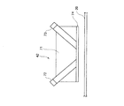
更に、本実施の形態では、濃度センサ42は、図7に示すように、中間転写ベルト20の上下振動幅sが許容範囲に収まる位置に対応して設定するようにすればよい。
すなわち、濃度センサ42と中間転写ベルト20との間の距離をdとし、Δdが濃度センサ42の許容ギャップ変化とすれば、中間転写ベルト20の上下振動幅sが2×Δd以内に収まるように設定すればよい。
例えば一次転写ロール105と張架ロール22との間の距離がLであり、このときの中間転写ベルト20の最大上下振動幅が許容振動幅(2×Δd)の10倍であると想定すれば、張架ロール22の中間転写ベルト20との接触開始点Pから上流側にL/20程度変位させることが可能である。
【0033】
◎実施の形態2
図8は本発明が適用された画像形成装置の実施の形態2を示す。
同図において、画像形成装置の基本的構成は実施の形態1と略同様であるが、濃度センサ42周辺の構造が実施の形態1と異なる。尚、実施の形態1と同様な構成要素については実施の形態1と同様な符号を付してここではその詳細な説明を省略する。
本実施の形態において、濃度センサ42は、実施の形態1と同様に、張架ロール22の中間転写ベルト20との接触開始点Pより上流3mm離間した位置に配設されているが、実施の形態1と異なり、金属製の張架ロール22にトナーと逆極性のバイアス電圧を電源81により印加し、濃度センサ42と中間転写ベルト20との間に接地したアース電極板82を配置し、張架ロール22とアース電極板82との間にトナーが飛散しにくい電界を形成したものである。
特に、本実施の形態では、アース電極板82は前記電界が強く形成されるように、中間転写ベルト20になるべく近づける方がよく、本例では中間転写ベルト20の上方3mm位置にアース電極板82を配置するようにした。
【0034】
また、アース電極板82を用いたときの濃度センサ42付近の詳細を図9に示す。
同図において、アース電極板82には、濃度センサ42の光源72から中間転写ベルト20に照射する光とその反射光を遮らないように開口83が設けられている。また、濃度センサ42下面の透明部材74の前記照射光と反射光の通過位置と前記開口83の回りには防塵スポンジ84が配置されている。防塵スポンジ84は空気を通さない材質なので、防塵スポンジ84に囲まれた空間は空気の移動が少なく、空気の移動がなければ飛散トナーが透明部材74に進入してくることはほとんど無い。上記防塵スポンジ84も濃度センサ42のトナー付着対策には有効である。
上述の構成により濃度センサ42の中間転写ベルト20に対向する透明部材74のトナー飛散によるトナー付着はほとんど無くなった。
【0035】
また、本実施の形態において、図6に示すように、第3の態様、すなわち、金属製張架ロール22へのバイアス印加+アース電極板82により、狭いトナー飛散域で且つトナー飛散量がすくなくなるため、プリンタ本体へのトナー飛散の防止効果がより高まる。
ここで、アース電極板82を無くし、金属製張架ロール22へのバイアス印加のみにすると、金属製張架ロール22へのバイアス印加+アース電極板82のような飛散防止効果は無い。これは、張架ロール22が単体でトナー極性と逆極性の電圧を持てば、トナーの飛散はある程度抑えられるが、トナー飛散しにくい電界を形成していないために、トナー飛散防止効果は少ない。
同様に、図9の濃度センサ42の最下面の透明部材74を導電性にしトナーと同極のバイアス電圧を印加しただけでは効果は低く、透明部材74へのバイアス電圧印加と同時にアース電極板82を設けて飛散トナーが透明部材74に付着しにくい電界を形成する必要がある。
尚、張架動ロール22は樹脂製でも導電性であれば同様の効果が得られ、金属ロールに薄い絶縁フィルムを被せても同様の効果が得られる。
【0036】
◎実施の形態3
図10は本発明が適用された画像形成装置の実施の形態3を示す。
同図において、画像形成装置の基本的構成は、実施の形態1と略同様であるが、実施の形態1と異なり、濃度センサ42の上流側にトナーを積極的に飛散させるための飛散部材90を配設したものである。これは実施の形態1で一次転写ロール105の下流側で中間転写ベルト20に最初に接触する部材の位置でトナー飛散が発生しやすいことを考慮したものである。尚、実施の形態1と同様な構成要素については実施の形態1と同様な符号を付してここではその詳細な説明を省略する。
本実施の形態において、飛散部材90は表面が中間転写ベルト20に接触していればよく、回転ロールでも固定の接触部材でもよい。
また、飛散部材90の表面は金属製がよいが、導電性でも、金属表面に薄い絶縁フィルムを覆っても効果は変わらない。また、飛散部材90にバイアス電圧を印加し、アース電極板82(実施の形態2参照)を配置すると、装置内のトナー汚れが効果的に防止される。
更に、本実施の形態では、濃度センサ42近傍の中間転写ベルト20の張架ロール22が導電性部材でも、金属ロール表面に薄い絶縁フィルムを覆っても効果は変わらない。
【0037】
【発明の効果】
以上説明してきたように、本発明によれば、像搬送ベルト上の可視像粒子飛散域から外れ、かつ、プロセス制御センサと像搬送ベルトとのギャップ変化が許容範囲に収まる部位にプロセス制御センサを配設するようにしたので、プロセス制御センサへの可視像粒子飛散に伴う汚れを有効に防止することができ、その分、プロセス制御センサによる作像プロセス制御を常時良好に行い、長時間使用しても常時良好な作像サイクルを確実に保証することができる。
特に、本発明によれば、転写手段は像担持体との間で像搬送ベルトをニップ搬送し、プロセス制御センサは像搬送ベルトのうち像担持体に対向する平面部に対応して設けられているため、プロセス制御センサの位置調整を容易に行うことができることに加えて、像搬送ベルトの平面部の位置精度が高い分、プロセス制御センサと像搬送ベルトとの間の位置精度をより良好に保つことができ、プロセス制御センサによる検出精度を良好に保つことができる。
【図面の簡単な説明】
【図1】 本発明に係る画像形成装置の概要を示す説明図である。
【図2】 実施の形態1に係る画像形成装置の全体構成を示す説明図である。
【図3】 実施の形態1の濃度センサの配設位置を示す説明図である。
【図4】 実施の形態1で用いられる濃度センサの詳細を示す説明図である。
【図5】 実施の形態1で濃度センサの好ましい配設位置を決定するための実験例を示す説明図である。
【図6】 実施の形態の張架ロールの条件を変更した際のトナー飛散域の変化状態を示す説明図である。
【図7】 実施の形態1の濃度センサの配設位置と像搬送ベルトの振動との関係を示す説明図である。
【図8】 実施の形態2に係る画像形成装置の概要を示す説明図である。
【図9】 実施の形態2で用いられる濃度センサ周辺部構造の詳細を示す説明図である。
【図10】 実施の形態3に係る画像形成装置の概要を示す説明図である。
【図11】 従来における画像形成装置の概要を示す説明図である。
【符号の説明】
1…像担持体,2…像搬送ベルト,3…張架ロール,4(4a〜4d)…転写手段,5…プロセス制御センサ,6…接触部材,7…飛散部材,A…可視像粒子飛散域,P…接触開始点,T…可視像[0001]
BACKGROUND OF THE INVENTION
The present invention relates to an image forming apparatus such as a printer or a copying machine, and in particular, in a mode in which a visible image on an image carrier is transferred to an image conveying belt that is circulated and rotated around a plurality of stretching rolls. The present invention relates to an improvement of an image forming apparatus provided with a process control sensor for controlling an image forming process relating to a visible image on a conveying belt.
[0002]
[Prior art]
In general, in an image forming apparatus such as a printer or a copying machine, the amount of developer (toner) developed or transferred onto an image carrier is measured in order to correct and control fluctuations in image density due to environmental changes and changes with time. A device in which a concentration sensor (measuring device) is provided is already known.
Here, as the density sensor, one that measures the amount of toner by irradiating the image carrier with light from a light source and receiving reflected light from the image carrier is known.
[0003]
However, since the measurement surface (detection surface) of the density sensor is provided so as to face the image carrier, the toner that is scattered little by little adheres to the measurement surface of the density sensor if printing is continued for a long period of time.
Here, if the toner adheres to the measurement surface of the density sensor, the measurement accuracy of the density sensor is lowered, and accurate toner amount measurement becomes impossible.
At this time, as the image density correction processing, the reference value and the measured value of the toner amount are compared, and the image density is controlled according to the comparison result. There has been a technical problem that density control cannot be performed and a stable image density cannot always be obtained.
[0004]
As a means for solving such a technical problem, a conductive transparent member that transmits light is provided on a light projecting / receiving surface of a density sensor facing an image carrier, and a bias voltage having the same polarity as that of toner is provided on the conductive transparent member. Such as a prior art (for example, Japanese Patent Laid-Open No. 5-119567) for preventing scattered toner from being applied by applying a toner and a prior art for changing a bias voltage in accordance with the polarity of the toner (for example, Japanese Patent Laid-Open No. 6-161177). Or a prior art in which a dustproof cover is provided on the light projecting / receiving surface of the density sensor and a minimum optical path hole is provided in the cover (for example, Japanese Utility Model Laid-Open No. 2-148156), or the toner is a density sensor The prior art (for example, Unexamined-Japanese-Patent No. 5-158315) etc. which generate | occur | produce the airflow which does not adhere to the light projection / reception surface of this is proposed.
[0005]
[Problems to be solved by the invention]
However, when an intermediate transfer belt is used as an image carrier and the amount of toner on the intermediate transfer belt is detected, the amount of toner scattered is larger than that when the amount of toner on the photosensitive drum is detected. It is not enough to adopt a dust-proof cover or a method to prevent this. The same applies to an image forming apparatus using a sheet conveying belt instead of the intermediate transfer belt.
The reason described above will be described in detail below.
[0006]
FIG. 11 is a configuration diagram in the vicinity of a density sensor that detects the amount of toner on a primary transfer and an intermediate transfer belt of an image forming apparatus that employs an intermediate transfer method, for example.
In the figure,
In such an apparatus configuration, for example, a negative (−)
[0007]
At this time, the back surface of the
On the other hand, the distance accuracy between the
In this state, when the
[0008]
Here, it is conceivable that the
Certainly, according to this method, since the
[0009]
In this case, as described above, even if the method of electrically preventing toner scattering or the method of using a dust-proof cover is implemented, there is a certain effect, but a small amount of toner is scattered on the
Furthermore, even if a technology for generating an air flow so that toner does not adhere to the measurement surface of the density sensor is used, the apparatus configuration is complicated and the implementation to a general-purpose printer is difficult because the air flow generation pump is indispensable. .
[0010]
The following experiment verified that the above-described method for electrically preventing toner scattering was insufficient.
That is, the toner image on the
Under such circumstances, there is a technique for changing the bias voltage to the tension roll according to the charging polarity of the toner, as in the technique described in Japanese Patent Laid-Open No. 6-161177, for example. When there are charged toners having different values, it is easily assumed that toner scattering cannot be prevented at a certain voltage.
[0011]
In the above example, the density sensor has been described. However, the position detection sensor for detecting the image writing position from the mark image written on the
The present invention has been made to solve the above technical problem, and is based on an image forming apparatus that includes an image conveyance belt and performs process control with a process control sensor.While maintaining good detection accuracy of the process control sensor,It is an object of the present invention to provide an image forming apparatus capable of effectively preventing contamination due to visible image particles on a measurement surface of a process control sensor.
[0012]
[Means for Solving the Problems]
That is, as shown in FIG. 1, the present invention includes one or a plurality of image carriers 1 (for example, 1a to 1d) for forming and supporting a visible image (for example, a toner image) T made of charged particles, and a plurality of stretches. A volume resistivity of 10 which is circulated and rotated around the
[0013]
In such technical means, the present case includes any of a tandem type and a four-cycle type.
The
Furthermore,The
Furthermore,The
Also, Contact member 6asNot only the
In this case, the other members also include a scattering member 7 (shown in phantom lines) provided separately from the stretching
[0014]
The
Here, the contact member 6 that first comes into contact with the
Then, once the visible image particles are scattered on the
Furthermore, since the visible image particle scattering area A changes depending on the condition of the contact member 6 and the like, the visible image particle scattering area A is selected in consideration of the condition of the contact member 6 and the like.
Furthermore, “the change in the gap d with the
[0015]
Further, the
In particular, as an aspect in consideration of the ease of position adjustment of the
[0016]
The
Further, regarding the contact member 6 that first comes into contact with the
[0017]
The contact member 6 that first contacts the
[0018]
Further, as a mode for more effectively suppressing the scattering of visible image particles on the
In order to more effectively prevent the scattered visible image particles from adhering to the
[0019]
DETAILED DESCRIPTION OF THE INVENTION
Hereinafter, the present invention will be described in detail based on embodiments shown in the accompanying drawings.
FIG. 2 shows
In the figure, the image forming apparatus according to the present embodiment is, for example, an intermediate transfer type tandem image forming apparatus, for example, a plurality of image forming units 10 (specific examples) in which each color component toner image is formed by electrophotography. Specifically, 10Y, 10M, 10C, and 10K), an
[0020]
In the present embodiment, the
Each
[0021]
Further, the
Here, the
As the
[0022]
Further, a direct current bias having a polarity opposite to the charging polarity of the toner (positive polarity in the present embodiment) is applied to the
On the other hand, the batch transfer device 30 is provided with a
[0023]
In this embodiment,
[0024]
Further, in the present embodiment, the paper transport system feeds the paper P from the
[0025]
In particular, in this embodiment,
In the present embodiment, the developing
However, in order to maintain the printer image quality, it is necessary to always keep the amount of toner on the
[0026]
The configuration of the
The
Further, the entire surface of the
As a control method using the
[0027]
In the present embodiment, the structure near the
In FIG. 3, a stretch roll (driven roll) 22 is made of a metal roll and is grounded.
Here, the toner image T on the
[0028]
In this embodiment, if the distance from the
[0029]
Here, the reason for determining the arrangement position of the
FIG. 5 shows an arrangement example of the
For example, it is the position (I) between the
At this time, when the
Also, the position of (III) that faces the curved surface portion of the
Furthermore, it may be in the position (IV) facing the tension roll 23 (the tension roll in this example) located at the downstream position, but the
From the above points, the optimum mounting position of the
Further, once the
[0030]
Further, when the toner scattering area was changed in accordance with the conditions of the
In the figure, (1) When the tension roll (driven roll) 22 is made of resin or the like, (2) When the
In this experiment, a thin insulating film is placed in a portion facing the
[0031]
As a result, it was found that the toner scattering area becomes a narrow range (a: 4 mm) by making the
In addition, it was found that when the
For this reason, it is understood that the scattered toner hardly adheres to the
In the present embodiment, as shown in FIG. 6, the density sensor is arranged at a position Q separated by c (3 mm in this example) upstream from the contact start point P between the
[0032]
Further, in the present embodiment, as shown in FIG. 7, the
That is, if the distance between the
For example, assuming that the distance between the
[0033]
FIG. 8 shows
In the figure, the basic configuration of the image forming apparatus is substantially the same as that of the first embodiment, but the structure around the
In the present embodiment, the
In particular, in the present embodiment, the
[0034]
FIG. 9 shows details of the vicinity of the
In the drawing, an opening 83 is provided in the
With the above-described configuration, toner adhesion due to toner scattering on the
[0035]
In the present embodiment, as shown in FIG.ThirdIn other words, the bias application to the
Here, if the
Similarly, if the
The
[0036]
FIG. 10 shows
In the figure, the basic configuration of the image forming apparatus is substantially the same as that of the first embodiment, but unlike the first embodiment, a scattering
In the present embodiment, the scattering
The surface of the scattering
Further, in the present embodiment, the effect does not change even if the
[0037]
【The invention's effect】
As described above, according to the present invention, the process control sensor is located at a part that is out of the visible image particle scattering region on the image transport belt and the gap change between the process control sensor and the image transport belt is within an allowable range. Therefore, it is possible to effectively prevent contamination due to scattering of visible image particles to the process control sensor. Even if it is used, it is possible to ensure a good image forming cycle at all times.
In particular, according to the present inventionThe transfer means conveys the image conveying belt between the image carrier and the nip,Since the process control sensor is provided corresponding to the plane portion of the image transport belt that faces the image carrier, the position of the process control sensor can be easily adjusted. Therefore, the positional accuracy between the process control sensor and the image conveying belt can be kept better, and the detection accuracy by the process control sensor can be kept good.
[Brief description of the drawings]
FIG. 1 is an explanatory diagram showing an outline of an image forming apparatus according to the present invention.
FIG. 2 is an explanatory diagram illustrating an overall configuration of the image forming apparatus according to the first embodiment.
FIG. 3 is an explanatory diagram showing the arrangement position of the density sensor according to the first embodiment.
FIG. 4 is an explanatory diagram showing details of the concentration sensor used in the first embodiment.
FIG. 5 is an explanatory diagram showing an experimental example for determining a preferred arrangement position of the density sensor in the first embodiment.
FIG. 6 is an explanatory diagram showing a change state of the toner scattering area when the condition of the tension roll according to the embodiment is changed.
7 is an explanatory diagram showing a relationship between the position where the density sensor according to
FIG. 8 is an explanatory diagram showing an overview of an image forming apparatus according to a second embodiment.
FIG. 9 is an explanatory diagram illustrating details of a peripheral structure of a concentration sensor used in the second embodiment.
FIG. 10 is an explanatory diagram showing an overview of an image forming apparatus according to a third embodiment.
FIG. 11 is an explanatory diagram showing an outline of a conventional image forming apparatus.
[Explanation of symbols]
DESCRIPTION OF
Claims (6)
プロセス制御センサは、像搬送ベルトのうち像担持体に対向する平面部に対応して設けられ、最終転写手段の下流側で像搬送ベルトよりも導電性が高く像搬送ベルトに最初に接触する接触部材の像搬送ベルトへの接触開始点を含む可視像粒子飛散域から外れた位置で、かつ、像搬送ベルトとの間のギャップ変化が許容範囲に収まるように像搬送ベルトの上下振動幅が抑えられた安定搬送領域に対向配置されていることを特徴とする画像形成装置。One or a plurality of image carriers for forming and supporting a visible image made of charged particles, and a volume resistivity of 10 8 to 10 14 Ω that circulates and rotates around a plurality of stretching rolls and conveys the visible image. One or a plurality of transfer means for transferring the visible image on the image carrier directly or indirectly to the image carrier belt while nip-conveying the image carrier belt between the cm image carrier belt and the image carrier And a process control sensor for detecting image forming process control information relating to a visible image on the image conveying belt,
The process control sensor is provided corresponding to the flat portion of the image transport belt that faces the image carrier, and has a higher conductivity than the image transport belt on the downstream side of the final transfer unit, and is the first contact with the image transport belt. The vertical vibration width of the image conveying belt is at a position that is out of the visible image particle scattering region including the contact start point of the member to the image conveying belt and the gap change with the image conveying belt is within an allowable range. An image forming apparatus, wherein the image forming apparatus is disposed opposite to a suppressed stable conveyance region.
最終転写手段の下流側で像搬送ベルトに最初に接触する接触部材は、導電性部材で接地されていることを特徴とする画像形成装置。The image forming apparatus according to claim 1.
An image forming apparatus, wherein a contact member that first contacts the image conveying belt on the downstream side of the final transfer unit is grounded by a conductive member.
最終転写手段の下流側で像搬送ベルトに最初に接触する接触部材は、導電性部材を絶縁被覆したものであることを特徴とする画像形成装置。The image forming apparatus according to claim 1.
The image forming apparatus according to claim 1, wherein the contact member that first contacts the image conveying belt on the downstream side of the final transfer unit is an insulating coating of a conductive member.
プロセス制御センサの近傍に位置する接触部材には、像搬送ベルト上の可視像粒子と逆極性のバイアスを印加したことを特徴とする画像形成装置。The image forming apparatus according to claim 1.
An image forming apparatus, wherein a bias having a polarity opposite to that of visible image particles on an image conveying belt is applied to a contact member located in the vicinity of a process control sensor.
プロセス制御センサと像搬送ベルトとの間には接地された電極部材を設け、この電極部材を利用してプロセス制御センサに可視像粒子が付着しにくい電界を形成することを特徴とする画像形成装置。The image forming apparatus according to claim 1.
An image member characterized in that a grounded electrode member is provided between the process control sensor and the image conveying belt, and an electric field that prevents visible image particles from adhering to the process control sensor is formed using the electrode member. apparatus.
最終転写手段の下流側で像搬送ベルトに最初に接触する接触部材は、像搬送ベルト上の可視像粒子を積極的に飛散させるために張架ロールと別個に設けられる飛散部材であることを特徴とする画像形成装置。The image forming apparatus according to claim 1.
The contact member that first contacts the image conveying belt on the downstream side of the final transfer unit is a scattering member that is provided separately from the stretching roll in order to actively scatter visible image particles on the image conveying belt. A featured image forming apparatus.
Priority Applications (1)
| Application Number | Priority Date | Filing Date | Title |
|---|---|---|---|
| JP31414199A JP3659312B2 (en) | 1999-11-04 | 1999-11-04 | Image forming apparatus |
Applications Claiming Priority (1)
| Application Number | Priority Date | Filing Date | Title |
|---|---|---|---|
| JP31414199A JP3659312B2 (en) | 1999-11-04 | 1999-11-04 | Image forming apparatus |
Publications (3)
| Publication Number | Publication Date |
|---|---|
| JP2001134047A JP2001134047A (en) | 2001-05-18 |
| JP2001134047A5 JP2001134047A5 (en) | 2004-10-28 |
| JP3659312B2 true JP3659312B2 (en) | 2005-06-15 |
Family
ID=18049730
Family Applications (1)
| Application Number | Title | Priority Date | Filing Date |
|---|---|---|---|
| JP31414199A Expired - Lifetime JP3659312B2 (en) | 1999-11-04 | 1999-11-04 | Image forming apparatus |
Country Status (1)
| Country | Link |
|---|---|
| JP (1) | JP3659312B2 (en) |
Cited By (1)
| Publication number | Priority date | Publication date | Assignee | Title |
|---|---|---|---|---|
| US9874843B2 (en) | 2015-06-02 | 2018-01-23 | Canon Kabushiki Kaisha | Image forming apparatus |
Families Citing this family (3)
| Publication number | Priority date | Publication date | Assignee | Title |
|---|---|---|---|---|
| JP4974282B2 (en) * | 2007-03-29 | 2012-07-11 | 株式会社リコー | Belt device and image forming apparatus |
| EP1975737B1 (en) | 2007-03-29 | 2015-01-07 | Ricoh Company, Ltd. | Belt device, belt deviation detecting device, and image forming apparatus |
| JP4562147B2 (en) * | 2007-09-26 | 2010-10-13 | 株式会社沖データ | Image forming apparatus |
-
1999
- 1999-11-04 JP JP31414199A patent/JP3659312B2/en not_active Expired - Lifetime
Cited By (1)
| Publication number | Priority date | Publication date | Assignee | Title |
|---|---|---|---|---|
| US9874843B2 (en) | 2015-06-02 | 2018-01-23 | Canon Kabushiki Kaisha | Image forming apparatus |
Also Published As
| Publication number | Publication date |
|---|---|
| JP2001134047A (en) | 2001-05-18 |
Similar Documents
| Publication | Publication Date | Title |
|---|---|---|
| JP4027287B2 (en) | Image forming apparatus | |
| US6909859B2 (en) | Charging apparatus with plural charging means | |
| JP3325136B2 (en) | Image forming device | |
| US6226469B1 (en) | System for reducing toner scattering | |
| JP3110539B2 (en) | Image forming device | |
| US20010051061A1 (en) | Image forming apparatus capable of preventing damage to photosensitive body by charging particle | |
| JP2022059719A (en) | Image forming apparatus | |
| JP3659312B2 (en) | Image forming apparatus | |
| US6393238B1 (en) | Image forming apparatus featuring a particle carrying charging member and a developing device including a magnetic field generating device | |
| JPH10232574A (en) | Image forming device | |
| JP2022059718A (en) | Developing device and image forming apparatus including the same | |
| JP2002182491A (en) | Transfer/carrying belt device and image forming apparatus | |
| JP2000221776A (en) | Developing device | |
| US6006048A (en) | Wrong-sign toner detection system | |
| US5140373A (en) | Electrostatic latent image developing apparatus with bristle height adjusting member | |
| JP2003241544A (en) | Image forming apparatus | |
| JPH11174871A (en) | Image forming device | |
| JP2004191842A (en) | Image forming apparatus | |
| JP3438585B2 (en) | Developing device | |
| US20010043820A1 (en) | Image forming apparatus and process cartridge detachably attachable thereto | |
| JPH11149194A (en) | Image forming device | |
| JPH11149195A (en) | Image forming device | |
| JP2002258614A (en) | Image forming apparatus | |
| JPH04153671A (en) | Electrophotographic copying device | |
| JP2002040742A (en) | Image forming device |
Legal Events
| Date | Code | Title | Description |
|---|---|---|---|
| A977 | Report on retrieval |
Free format text: JAPANESE INTERMEDIATE CODE: A971007 Effective date: 20040415 |
|
| A131 | Notification of reasons for refusal |
Free format text: JAPANESE INTERMEDIATE CODE: A131 Effective date: 20040427 |
|
| A521 | Request for written amendment filed |
Free format text: JAPANESE INTERMEDIATE CODE: A523 Effective date: 20040625 |
|
| A131 | Notification of reasons for refusal |
Free format text: JAPANESE INTERMEDIATE CODE: A131 Effective date: 20041019 |
|
| A521 | Request for written amendment filed |
Free format text: JAPANESE INTERMEDIATE CODE: A523 Effective date: 20041215 |
|
| TRDD | Decision of grant or rejection written | ||
| A01 | Written decision to grant a patent or to grant a registration (utility model) |
Free format text: JAPANESE INTERMEDIATE CODE: A01 Effective date: 20050223 |
|
| A61 | First payment of annual fees (during grant procedure) |
Free format text: JAPANESE INTERMEDIATE CODE: A61 Effective date: 20050308 |
|
| R150 | Certificate of patent or registration of utility model |
Ref document number: 3659312 Country of ref document: JP Free format text: JAPANESE INTERMEDIATE CODE: R150 Free format text: JAPANESE INTERMEDIATE CODE: R150 |
|
| FPAY | Renewal fee payment (event date is renewal date of database) |
Free format text: PAYMENT UNTIL: 20080325 Year of fee payment: 3 |
|
| FPAY | Renewal fee payment (event date is renewal date of database) |
Free format text: PAYMENT UNTIL: 20090325 Year of fee payment: 4 |
|
| FPAY | Renewal fee payment (event date is renewal date of database) |
Free format text: PAYMENT UNTIL: 20100325 Year of fee payment: 5 |
|
| FPAY | Renewal fee payment (event date is renewal date of database) |
Free format text: PAYMENT UNTIL: 20110325 Year of fee payment: 6 |
|
| FPAY | Renewal fee payment (event date is renewal date of database) |
Free format text: PAYMENT UNTIL: 20120325 Year of fee payment: 7 |
|
| FPAY | Renewal fee payment (event date is renewal date of database) |
Free format text: PAYMENT UNTIL: 20130325 Year of fee payment: 8 |
|
| FPAY | Renewal fee payment (event date is renewal date of database) |
Free format text: PAYMENT UNTIL: 20130325 Year of fee payment: 8 |
|
| FPAY | Renewal fee payment (event date is renewal date of database) |
Free format text: PAYMENT UNTIL: 20140325 Year of fee payment: 9 |
|
| EXPY | Cancellation because of completion of term |