EP1975543A1 - Device for hanging a game board - Google Patents
Device for hanging a game board Download PDFInfo
- Publication number
- EP1975543A1 EP1975543A1 EP08005796A EP08005796A EP1975543A1 EP 1975543 A1 EP1975543 A1 EP 1975543A1 EP 08005796 A EP08005796 A EP 08005796A EP 08005796 A EP08005796 A EP 08005796A EP 1975543 A1 EP1975543 A1 EP 1975543A1
- Authority
- EP
- European Patent Office
- Prior art keywords
- carrier
- holder
- polygonal part
- shaped
- game board
- Prior art date
- Legal status (The legal status is an assumption and is not a legal conclusion. Google has not performed a legal analysis and makes no representation as to the accuracy of the status listed.)
- Withdrawn
Links
- 238000010276 construction Methods 0.000 description 5
- 239000000463 material Substances 0.000 description 2
Images
Classifications
-
- F—MECHANICAL ENGINEERING; LIGHTING; HEATING; WEAPONS; BLASTING
- F41—WEAPONS
- F41J—TARGETS; TARGET RANGES; BULLET CATCHERS
- F41J3/00—Targets for arrows or darts, e.g. for sporting or amusement purposes
- F41J3/0009—Dartboards
- F41J3/0014—Dartboard holders
- F41J3/0019—Stands or wall mountings especially adapted for dartboards
Definitions
- the invention relates to a device for hanging a game board, in particular a dart board, which device comprises a holder to be fixed to a wall or the like and a carrier to be attached to the game board, said holder and said carrier, being provided with means for disposing the holder and the carrier in various rotated positions relative to each other.
- players throw their darts invariably at the same location on the dart board, generally the upper part of the dart board, when using a dart board, so that after some time said part of the dart board will be damaged to such an extent that this part of the dart board can no longer be used effectively. Consequently it is usual to manually rotate the dart board through a certain angle about an imaginary axis extending perpendicularly to the front surface of the dart board after part of the dart board has become damaged. Disposing the dart board in a correct, new position after rotation thereof is generally very time-consuming.
- a device for hanging a dart board which comprises a holder to be fixed to a wall or the like, which holder is provided with a projecting, circular disc on its side remote from the wall, around which a support plate for a dart board is rotatable. Furthermore, a plate provided with a keyhole is fixed to one end of the disc, via which keyhole a dart board can be hung from the disc.
- both the support plate and the dart board can be rotated, but in spite of the rather complex and voluminous construction of this known device, it is not possible to effect a simple and precise rotation of the game board through a desired angle.
- WO 91/15729 and GB 503,045 also show devices for rotatably hanging a game board.
- the construction of these devices, too, is complex and voluminous, and the devices have a comparatively large dimension in a direction perpendicular to the front surface of the game board.
- AU 656,646 shows an embodiment in which a game board can be attached to a wall by means of Velcro. With this construction, too, it is practically impossible to effect a simple and precise rotation of a game board through a desired angular distance.
- a device for hanging a dart board wherein a positioning element provided with projections is attached to the rear side of the dart board.
- the projections of said positioning element fit in corresponding recesses formed in a holder that is fixed to a wall.
- the dart board can be moved against the action of spring means in a direction perpendicular to the front surface of the dart board so as to move the projections out of the recesses. After a desired rotation of the dart board, the projections will be pressed into the recesses again under the influence of the spring force.
- the object of the invention is to provide a device of simple and compact construction, by means of which a game board supported by the device can be rotated through a desired angle in a precise and simple manner.
- this object can be accomplished in that the carrier is provided with two disc-shaped regular polygonal parts, wherein one polygonal part projects outside the other polygonal part, with the smaller polygonal part of the carrier fitting between the legs of the U-shaped holder and the larger polygonal part of the carrier fitting in a recess formed on one side of the holder, all this in such a manner that the carrier can be moved to and from a position between the legs of the U-shaped holder, whilst at least a few edges of a polygonal part of the carrier abut against edges of the U-shaped holder in the position in which the carrier is connected to the holder.
- the game board can be easily rotated through a desired angle by moving the carrier out of the holder and moving it back into the holder again after rotation of the game board.
- the dimension of the carrier and the holder in a direction perpendicular to the front surface of the game board supported by the holder can be small in that case, so that the distance between the front surface of the game board and the wall the like to which the holder is fixed can be small.
- the invention further relates to a game board provided with a carrier comprising two disc-shaped regular polygonal parts, wherein one polygonal part projects outside the other polygonal part, as well as to a combination of a game board provided with a carrier comprising two disc-shaped regular polygonal parts, one polygonal part projecting outside the other polygonal part, and with a U-shaped holder, between the legs of which U-shaped holder the smaller polygonal part of the carrier fits, whilst the larger part of the carrier fits in a recess formed on one side of the holder, all this in such a manner that the carrier can be moved to and from a position between the legs of the U-shaped holder, whilst at least a few edges of a polygonal part of the carrier abut against edges of the U-shaped holder in the position in which the carrier is connected to the holder.
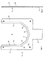
- Figure 1 is a front view of a holder for a device according to the invention.
- Figure 2 is a side view of figure 1 .
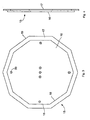
- Figure 3 is a front view of a carrier for a device according to the invention.
- Figure 4 is a side view of the carrier of figure 3 .
- the holder 1 shown in figure 1 which is usually made of plastic material, is substantially U-shaped, seen in front view, and comprises a projection 2 which extends below the U-shaped part.
- the two parallel legs 3 and 4 of the holder define a recess 5, which is bounded at the bottom side by four boundary edges 6-9 that join each other, which boundary edges include angles of ⁇ 150° with each other.
- the angles between the parallel edges 10 and 11 of the two legs 3 and 4 and their adjoining edges 6 and 9, respectively, are likewise ⁇ 150°.
- a groove or recess 12 is formed at the rear side of the holder 1, which groove or recess extends along the circumference of the recess 5 and whose boundary edge 13 remote from the recess 5 extends parallel to the edges 6-11 of the opening 5.
- the holder 1 is further provided with a few holes 14, through which screws for fixing the holder 1 to a wall or the like can be passed.
- the device according to the invention further comprises the carrier 15, for example of plastic material, that is shown in figures 3 and 4 , which carrier comprises a first flat disc 16 and a second flat disc 17 attached to one side thereof.
- the flat disc 16 has the shape of a regular decagonal disc, with the magnitude of an angle between two successive boundary edges 18 of the disc being ⁇ 150°.
- the disc 17 is a correspondingly regular decagon, which, as figures 3 and 4 show, projects outside the disc 16 and which is disposed in such a manner that the edges 19 of the disc 17 extend parallel to the edges 18 of the disc 16.
- a game board such as a dart board, can be attached to the surface of the disc 16 remote from the disc 17, for example by means of screws or the like passed through holes 20 formed in the discs.
- the carrier 15 can be connected to the holder by moving the disc 16 into the space defined by the recess 5 and the disc 17 in the recess 12 formed in the rear side of the holder 1, which joins the recess 5. It will be understood that the carrier 15 is locked against rotation with respect to the holder 1 as a result of its unround shape, the decagonal shape of he discs 16 and 17 in the illustrated case, with the edges 18 of the disc 16 abutting against the edges 6-11 of the recess 5 and the edges 19 of the disc 17 abutting against the boundary edge 13 of the recess 12.
- the carrier 15 can be moved out of the holder 1 and be moved back into the holder 1 again after being rotated through a desired angle.
- a game board attached to the carrier 15 will be held in a stable position when the game board is being used for playing, whilst the position of the game board can be changed in a simple manner, if desired, by rotating the board about an imaginary axis extending perpendicularly to the plane of the game board after the carrier 15 has been taken out of the holder 1.
Landscapes
- Engineering & Computer Science (AREA)
- General Engineering & Computer Science (AREA)
- Toys (AREA)
- Pinball Game Machines (AREA)
Abstract
Description
- The invention relates to a device for hanging a game board, in particular a dart board, which device comprises a holder to be fixed to a wall or the like and a carrier to be attached to the game board, said holder and said carrier, being provided with means for disposing the holder and the carrier in various rotated positions relative to each other.
- Generally, players throw their darts invariably at the same location on the dart board, generally the upper part of the dart board, when using a dart board, so that after some time said part of the dart board will be damaged to such an extent that this part of the dart board can no longer be used effectively. Consequently it is usual to manually rotate the dart board through a certain angle about an imaginary axis extending perpendicularly to the front surface of the dart board after part of the dart board has become damaged. Disposing the dart board in a correct, new position after rotation thereof is generally very time-consuming.
- From
GB 734,541 -
WO 91/15729 GB 503,045 -
AU 656,646 - From prior document
NL 1030205 - This construction, too, is complicated, whilst the front surface of the game board is spaced a comparatively large distance from the wall or the like to which the holder is fixed.
- The object of the invention is to provide a device of simple and compact construction, by means of which a game board supported by the device can be rotated through a desired angle in a precise and simple manner.
- According to the invention, this object can be accomplished in that the carrier is provided with two disc-shaped regular polygonal parts, wherein one polygonal part projects outside the other polygonal part, with the smaller polygonal part of the carrier fitting between the legs of the U-shaped holder and the larger polygonal part of the carrier fitting in a recess formed on one side of the holder, all this in such a manner that the carrier can be moved to and from a position between the legs of the U-shaped holder, whilst at least a few edges of a polygonal part of the carrier abut against edges of the U-shaped holder in the position in which the carrier is connected to the holder.
- When use is made of the device according to the invention, the game board can be easily rotated through a desired angle by moving the carrier out of the holder and moving it back into the holder again after rotation of the game board. The dimension of the carrier and the holder in a direction perpendicular to the front surface of the game board supported by the holder can be small in that case, so that the distance between the front surface of the game board and the wall the like to which the holder is fixed can be small.
- The invention further relates to a game board provided with a carrier comprising two disc-shaped regular polygonal parts, wherein one polygonal part projects outside the other polygonal part, as well as to a combination of a game board provided with a carrier comprising two disc-shaped regular polygonal parts, one polygonal part projecting outside the other polygonal part, and with a U-shaped holder, between the legs of which U-shaped holder the smaller polygonal part of the carrier fits, whilst the larger part of the carrier fits in a recess formed on one side of the holder, all this in such a manner that the carrier can be moved to and from a position between the legs of the U-shaped holder, whilst at least a few edges of a polygonal part of the carrier abut against edges of the U-shaped holder in the position in which the carrier is connected to the holder.
- The invention will be explained in more detail hereinafter with reference to an embodiment of a device according to the invention as shown in the appended figures.
-
Figure 1 is a front view of a holder for a device according to the invention. -
Figure 2 is a side view offigure 1 . -
Figure 3 is a front view of a carrier for a device according to the invention. -
Figure 4 is a side view of the carrier offigure 3 . - The holder 1 shown in
figure 1 , which is usually made of plastic material, is substantially U-shaped, seen in front view, and comprises aprojection 2 which extends below the U-shaped part. The two parallel legs 3 and 4 of the holder define a recess 5, which is bounded at the bottom side by four boundary edges 6-9 that join each other, which boundary edges include angles of ± 150° with each other. The angles between theparallel edges adjoining edges 6 and 9, respectively, are likewise ± 150°. - Furthermore, a groove or
recess 12 is formed at the rear side of the holder 1, which groove or recess extends along the circumference of the recess 5 and whoseboundary edge 13 remote from the recess 5 extends parallel to the edges 6-11 of the opening 5. - The holder 1 is further provided with a
few holes 14, through which screws for fixing the holder 1 to a wall or the like can be passed. - The device according to the invention further comprises the
carrier 15, for example of plastic material, that is shown infigures 3 and 4 , which carrier comprises a firstflat disc 16 and a secondflat disc 17 attached to one side thereof. As will be understood, theflat disc 16 has the shape of a regular decagonal disc, with the magnitude of an angle between twosuccessive boundary edges 18 of the disc being ± 150°. - The
disc 17 is a correspondingly regular decagon, which, asfigures 3 and 4 show, projects outside thedisc 16 and which is disposed in such a manner that theedges 19 of thedisc 17 extend parallel to theedges 18 of thedisc 16. - A game board, such as a dart board, can be attached to the surface of the
disc 16 remote from thedisc 17, for example by means of screws or the like passed throughholes 20 formed in the discs. - When the holder 1 is fixed to a wall or the like, the
carrier 15 can be connected to the holder by moving thedisc 16 into the space defined by the recess 5 and thedisc 17 in therecess 12 formed in the rear side of the holder 1, which joins the recess 5. It will be understood that thecarrier 15 is locked against rotation with respect to the holder 1 as a result of its unround shape, the decagonal shape of he discs 16 and 17 in the illustrated case, with theedges 18 of thedisc 16 abutting against the edges 6-11 of the recess 5 and theedges 19 of thedisc 17 abutting against theboundary edge 13 of therecess 12. - When the game board needs to be placed in a different position, the
carrier 15 can be moved out of the holder 1 and be moved back into the holder 1 again after being rotated through a desired angle. - It will be understood that by using the device according to the invention, a game board attached to the
carrier 15 will be held in a stable position when the game board is being used for playing, whilst the position of the game board can be changed in a simple manner, if desired, by rotating the board about an imaginary axis extending perpendicularly to the plane of the game board after thecarrier 15 has been taken out of the holder 1. - Although the invention has been explained in particular on the basis of the use thereof with a dart board, it will be apparent that the device according to the invention can also be used with other game boards.
Claims (3)
- A device for hanging a game board, in particular a dart board, which device comprises a holder to be fixed to a wall or the like and a carrier to be attached to the game board, said holder and said carrier being provided with means for disposing the holder and the carrier in various rotated positions relative to each other, characterised in that the carrier is provided with two disc-shaped regular polygonal parts, wherein one polygonal part projects outside the other polygonal part, with the smaller polygonal part of the carrier fitting between the legs of the U-shaped holder and the larger polygonal part of the carrier fitting in a recess formed on one side of the holder, all this in such a manner that the carrier can be moved to and from a position between the legs of the U-shaped holder, whilst at least a few edges of a polygonal part of the carrier abut against edges of the U-shaped holder in the position in which the carrier is connected to the holder.
- A game board provided with a carrier comprising two disc-shaped regular polygonal parts, wherein one polygonal part projects outside the other polygonal part.
- A combination of a game board provided with a carrier comprising two disc-shaped regular polygonal parts, one polygonal part projecting outside the other polygonal part, and with a U-shaped holder, between the legs of which U-shaped holder the smaller polygonal part of the carrier fits, whilst the larger part of the carrier fits in a recess formed on one side of the holder, all this in such a manner that the carrier can be moved to and from a position between the legs of the U-shaped holder, whilst at least a few edges of a polygonal part of the carrier abut against edges of the U-shaped holder in the position in which the carrier is connected to the holder.
Applications Claiming Priority (1)
| Application Number | Priority Date | Filing Date | Title |
|---|---|---|---|
| NL1033617A NL1033617C2 (en) | 2007-03-30 | 2007-03-30 | Device for suspending a game board. |
Publications (1)
| Publication Number | Publication Date |
|---|---|
| EP1975543A1 true EP1975543A1 (en) | 2008-10-01 |
Family
ID=38719729
Family Applications (1)
| Application Number | Title | Priority Date | Filing Date |
|---|---|---|---|
| EP08005796A Withdrawn EP1975543A1 (en) | 2007-03-30 | 2008-03-27 | Device for hanging a game board |
Country Status (2)
| Country | Link |
|---|---|
| EP (1) | EP1975543A1 (en) |
| NL (1) | NL1033617C2 (en) |
Cited By (1)
| Publication number | Priority date | Publication date | Assignee | Title |
|---|---|---|---|---|
| WO2010048663A1 (en) * | 2008-10-28 | 2010-05-06 | David Francis Fitzpatrick | An apparatus for mounting a game board |
Citations (5)
| Publication number | Priority date | Publication date | Assignee | Title |
|---|---|---|---|---|
| GB503045A (en) | 1938-02-17 | 1939-03-30 | John Arthur Ellam | Improvements in or relating to dart boards |
| GB734541A (en) | 1953-03-05 | 1955-08-03 | May Wright | Improvements in dartboard backboards |
| WO1991015729A1 (en) | 1990-04-11 | 1991-10-17 | Wellow Leisure Products Limited | Improvements relating to target apparatus |
| AU656646B2 (en) | 1991-12-23 | 1995-02-09 | Thomas Edward Guy | Games board mounting bracket |
| NL1030205C1 (en) | 2005-10-16 | 2007-04-17 | Jacob Post | Toy projectile comprises housing in which is electronic circuitry of integrated type for emission of audio signals when activated |
Family Cites Families (1)
| Publication number | Priority date | Publication date | Assignee | Title |
|---|---|---|---|---|
| NL1030201C2 (en) * | 2005-10-14 | 2007-04-17 | Lee Christopher Mccolm | Dartboard hanging device, comprises pair of supports on wall and rear of board which have complimentary interlocking profiles to prevent board rotation |
-
2007
- 2007-03-30 NL NL1033617A patent/NL1033617C2/en not_active IP Right Cessation
-
2008
- 2008-03-27 EP EP08005796A patent/EP1975543A1/en not_active Withdrawn
Patent Citations (5)
| Publication number | Priority date | Publication date | Assignee | Title |
|---|---|---|---|---|
| GB503045A (en) | 1938-02-17 | 1939-03-30 | John Arthur Ellam | Improvements in or relating to dart boards |
| GB734541A (en) | 1953-03-05 | 1955-08-03 | May Wright | Improvements in dartboard backboards |
| WO1991015729A1 (en) | 1990-04-11 | 1991-10-17 | Wellow Leisure Products Limited | Improvements relating to target apparatus |
| AU656646B2 (en) | 1991-12-23 | 1995-02-09 | Thomas Edward Guy | Games board mounting bracket |
| NL1030205C1 (en) | 2005-10-16 | 2007-04-17 | Jacob Post | Toy projectile comprises housing in which is electronic circuitry of integrated type for emission of audio signals when activated |
Cited By (1)
| Publication number | Priority date | Publication date | Assignee | Title |
|---|---|---|---|---|
| WO2010048663A1 (en) * | 2008-10-28 | 2010-05-06 | David Francis Fitzpatrick | An apparatus for mounting a game board |
Also Published As
| Publication number | Publication date |
|---|---|
| NL1033617C2 (en) | 2008-10-02 |
Similar Documents
| Publication | Publication Date | Title |
|---|---|---|
| CN106869445B (en) | The adjustable wallboard mounting device in front | |
| USD600737S1 (en) | Tripod for photographic apparatuses | |
| CN209022036U (en) | It is a kind of for accommodating the instrument cases of tool heads | |
| CN101629671A (en) | Electronic device with multi-angle positioning support | |
| EP1867911A1 (en) | An assembly as well as a carrier, a support and a locking element suitable for use with such an assembly | |
| TWI567322B (en) | Display device | |
| CN206584260U (en) | Base portion for installing portable computing | |
| EP1975543A1 (en) | Device for hanging a game board | |
| JP4639066B2 (en) | Snowboard binding | |
| US20150103245A1 (en) | Tablet mount | |
| CN204366929U (en) | Adjustable angle box | |
| JP2021186668A (en) | Width adjustable hook | |
| TWI556715B (en) | Carrier | |
| US5351857A (en) | Writing instrument dispenser apparatus | |
| US20180244217A1 (en) | Adjustable license plate brackets | |
| GB2471337A (en) | Dartboard Mount | |
| JP4537691B2 (en) | Chair with panel | |
| KR101387237B1 (en) | Rotary device in engine stand for training | |
| CA2541565A1 (en) | Universal drain cover | |
| US12102268B2 (en) | Turntable cutting board device | |
| JP6092290B2 (en) | Holding device | |
| JP5892874B2 (en) | Device for processing the back of the book's contents | |
| KR20160065625A (en) | A changable circle table for corner | |
| TW201725066A (en) | Detachable dart target rotating device | |
| US791798A (en) | Book-finisher's stand. |
Legal Events
| Date | Code | Title | Description |
|---|---|---|---|
| PUAI | Public reference made under article 153(3) epc to a published international application that has entered the european phase |
Free format text: ORIGINAL CODE: 0009012 |
|
| AK | Designated contracting states |
Kind code of ref document: A1 Designated state(s): AT BE BG CH CY CZ DE DK EE ES FI FR GB GR HR HU IE IS IT LI LT LU LV MC MT NL NO PL PT RO SE SI SK TR |
|
| AX | Request for extension of the european patent |
Extension state: AL BA MK RS |
|
| 17P | Request for examination filed |
Effective date: 20090327 |
|
| AKX | Designation fees paid |
Designated state(s): AT BE BG CH CY CZ DE DK EE ES FI FR GB GR HR HU IE IS IT LI LT LU LV MC MT NL NO PL PT RO SE SI SK TR |
|
| RAP1 | Party data changed (applicant data changed or rights of an application transferred) |
Owner name: DARTBOARDFIX B.V. |
|
| 17Q | First examination report despatched |
Effective date: 20100308 |
|
| STAA | Information on the status of an ep patent application or granted ep patent |
Free format text: STATUS: THE APPLICATION IS DEEMED TO BE WITHDRAWN |
|
| 18D | Application deemed to be withdrawn |
Effective date: 20100720 |