EP1975525A1 - Air conditioner - Google Patents
Air conditioner Download PDFInfo
- Publication number
- EP1975525A1 EP1975525A1 EP07706803A EP07706803A EP1975525A1 EP 1975525 A1 EP1975525 A1 EP 1975525A1 EP 07706803 A EP07706803 A EP 07706803A EP 07706803 A EP07706803 A EP 07706803A EP 1975525 A1 EP1975525 A1 EP 1975525A1
- Authority
- EP
- European Patent Office
- Prior art keywords
- heat exchanger
- refrigerant
- paths
- flow
- path
- Prior art date
- Legal status (The legal status is an assumption and is not a legal conclusion. Google has not performed a legal analysis and makes no representation as to the accuracy of the status listed.)
- Withdrawn
Links
- 239000003507 refrigerant Substances 0.000 claims abstract description 78
- 230000033228 biological regulation Effects 0.000 claims abstract description 21
- 230000003247 decreasing effect Effects 0.000 claims description 8
- 238000010586 diagram Methods 0.000 description 6
- 230000007423 decrease Effects 0.000 description 3
- 230000000694 effects Effects 0.000 description 1
- 230000002427 irreversible effect Effects 0.000 description 1
- 238000011144 upstream manufacturing Methods 0.000 description 1
Images



Classifications
-
- F—MECHANICAL ENGINEERING; LIGHTING; HEATING; WEAPONS; BLASTING
- F24—HEATING; RANGES; VENTILATING
- F24F—AIR-CONDITIONING; AIR-HUMIDIFICATION; VENTILATION; USE OF AIR CURRENTS FOR SCREENING
- F24F1/00—Room units for air-conditioning, e.g. separate or self-contained units or units receiving primary air from a central station
- F24F1/0007—Indoor units, e.g. fan coil units
- F24F1/0059—Indoor units, e.g. fan coil units characterised by heat exchangers
- F24F1/0063—Indoor units, e.g. fan coil units characterised by heat exchangers by the mounting or arrangement of the heat exchangers
-
- F—MECHANICAL ENGINEERING; LIGHTING; HEATING; WEAPONS; BLASTING
- F25—REFRIGERATION OR COOLING; COMBINED HEATING AND REFRIGERATION SYSTEMS; HEAT PUMP SYSTEMS; MANUFACTURE OR STORAGE OF ICE; LIQUEFACTION SOLIDIFICATION OF GASES
- F25B—REFRIGERATION MACHINES, PLANTS OR SYSTEMS; COMBINED HEATING AND REFRIGERATION SYSTEMS; HEAT PUMP SYSTEMS
- F25B13/00—Compression machines, plants or systems, with reversible cycle
-
- F—MECHANICAL ENGINEERING; LIGHTING; HEATING; WEAPONS; BLASTING
- F25—REFRIGERATION OR COOLING; COMBINED HEATING AND REFRIGERATION SYSTEMS; HEAT PUMP SYSTEMS; MANUFACTURE OR STORAGE OF ICE; LIQUEFACTION SOLIDIFICATION OF GASES
- F25B—REFRIGERATION MACHINES, PLANTS OR SYSTEMS; COMBINED HEATING AND REFRIGERATION SYSTEMS; HEAT PUMP SYSTEMS
- F25B41/00—Fluid-circulation arrangements
- F25B41/20—Disposition of valves, e.g. of on-off valves or flow control valves
-
- F—MECHANICAL ENGINEERING; LIGHTING; HEATING; WEAPONS; BLASTING
- F25—REFRIGERATION OR COOLING; COMBINED HEATING AND REFRIGERATION SYSTEMS; HEAT PUMP SYSTEMS; MANUFACTURE OR STORAGE OF ICE; LIQUEFACTION SOLIDIFICATION OF GASES
- F25B—REFRIGERATION MACHINES, PLANTS OR SYSTEMS; COMBINED HEATING AND REFRIGERATION SYSTEMS; HEAT PUMP SYSTEMS
- F25B41/00—Fluid-circulation arrangements
- F25B41/30—Expansion means; Dispositions thereof
- F25B41/385—Dispositions with two or more expansion means arranged in parallel on a refrigerant line leading to the same evaporator
-
- F—MECHANICAL ENGINEERING; LIGHTING; HEATING; WEAPONS; BLASTING
- F25—REFRIGERATION OR COOLING; COMBINED HEATING AND REFRIGERATION SYSTEMS; HEAT PUMP SYSTEMS; MANUFACTURE OR STORAGE OF ICE; LIQUEFACTION SOLIDIFICATION OF GASES
- F25B—REFRIGERATION MACHINES, PLANTS OR SYSTEMS; COMBINED HEATING AND REFRIGERATION SYSTEMS; HEAT PUMP SYSTEMS
- F25B41/00—Fluid-circulation arrangements
- F25B41/30—Expansion means; Dispositions thereof
- F25B41/39—Dispositions with two or more expansion means arranged in series, i.e. multi-stage expansion, on a refrigerant line leading to the same evaporator
-
- F—MECHANICAL ENGINEERING; LIGHTING; HEATING; WEAPONS; BLASTING
- F25—REFRIGERATION OR COOLING; COMBINED HEATING AND REFRIGERATION SYSTEMS; HEAT PUMP SYSTEMS; MANUFACTURE OR STORAGE OF ICE; LIQUEFACTION SOLIDIFICATION OF GASES
- F25B—REFRIGERATION MACHINES, PLANTS OR SYSTEMS; COMBINED HEATING AND REFRIGERATION SYSTEMS; HEAT PUMP SYSTEMS
- F25B5/00—Compression machines, plants or systems, with several evaporator circuits, e.g. for varying refrigerating capacity
- F25B5/02—Compression machines, plants or systems, with several evaporator circuits, e.g. for varying refrigerating capacity arranged in parallel
-
- F—MECHANICAL ENGINEERING; LIGHTING; HEATING; WEAPONS; BLASTING
- F24—HEATING; RANGES; VENTILATING
- F24F—AIR-CONDITIONING; AIR-HUMIDIFICATION; VENTILATION; USE OF AIR CURRENTS FOR SCREENING
- F24F2140/00—Control inputs relating to system states
- F24F2140/20—Heat-exchange fluid temperature
-
- F—MECHANICAL ENGINEERING; LIGHTING; HEATING; WEAPONS; BLASTING
- F25—REFRIGERATION OR COOLING; COMBINED HEATING AND REFRIGERATION SYSTEMS; HEAT PUMP SYSTEMS; MANUFACTURE OR STORAGE OF ICE; LIQUEFACTION SOLIDIFICATION OF GASES
- F25B—REFRIGERATION MACHINES, PLANTS OR SYSTEMS; COMBINED HEATING AND REFRIGERATION SYSTEMS; HEAT PUMP SYSTEMS
- F25B2600/00—Control issues
- F25B2600/25—Control of valves
- F25B2600/2507—Flow-diverting valves
Definitions
- the present invention relates to an air conditioner, and more particularly, to an air conditioner including a flow divider for appropriately dividing the flow of refrigerant to a plurality of paths in an indoor heat exchanger of the air conditioner.
- Fig. 5 shows the structure of a typical wall-mount air conditioner (indoor equipment) 21 employing a cross flow fan 29.
- the air conditioner 21 includes a main body casing 20 having an upper surface in which a first air intake grille 23 is formed and a front surface upper portion in which a second air intake grille 24 is formed.
- the main body casing 20 also has an air discharge port 25 arranged in a lower corner of the front surface.
- An air passage 27 extends from the air intake grilles 23 and 24 to the air discharge port 25 in the main body casing 20.
- the indoor heat exchanger 26 is a lambda-type heat exchanger.
- a cross flow fan 29, a tongue 22, and a scroll 30 are arranged in the downstream region of the air passage 27.
- the cross flow fan 29 has an impeller (fan rotor) 29a, which is rotated in the direction of the arrow shown in Fig. 5 and which is arranged in an opening 22a of the tongue 22 and opening 30a of the scroll 30.
- the tongue 22 is located at a position facing toward the second air intake grill 24 and has a predetermined length along the outer circumference of the impeller (fan rotor) 29a in the cross flow fan 29.
- the tongue 22 has a lower portion that is continuous with an air flow guide 22b, which also serves as a drain pan and which is arranged below the indoor heat exchanger 26.
- the air flow guide 22b has a downstream portion, which extends toward the air discharge port 25 together with a downstream portion 30b of the scroll 30 and which forms an air discharge passage 28 having a diffuser structure as shown in the drawing.
- a stream deflection plate 31 is arranged in the air discharge passage 28 between the scroll 30 and the air flow guide 22b, which is located at the lower portion of the tongue 22.
- the tongue 22 is shaped as shown in Fig. 5 .
- the flow of air from the indoor heat exchanger 26 to the air discharge port 25 via the impeller (fan rotor) 29a of the cross flow fan 29 is curved in its entirety along the rotation direction of the impeller (fan rotor) 29a and discharged in a direction perpendicular to the rotation axis of the impeller (fan rotor) 29a. Then, the flow of air is curved along the air discharge passage 28 toward the air discharge port 25 and discharged out of the front surface of the air conditioner 21.
- the heat exchanger 26 was divided into portions A, B, C, and D to analyze the flow velocity distribution.
- the flow velocity in portion D which directly faces toward the second air intake grille 24, was the highest.
- the flow velocity was lower than portion D in portion C, which diagonally faces toward the first air intake grille 23.
- the flow velocity was lower than portion C in portion B, which is covered by the upper portion of the front surface of the main body casing 20 and thus does not directly receive the flow of air.
- the flow velocity was lower than portion B in portion A, which is blocked by the tongue 22 from the flow of air.
- An indoor heat exchanger 26 having a plurality of paths in an air conditioner as described above usually includes a flow divider 6 including branch flow paths 7a and 7b, as shown in Fig. 6 , to distribute the refrigerant that flows into the main body of the heat exchanger 26 into each path in the main body of the heat exchanger 26.
- the flow divider 6 determines the distribution ratio of the refrigerant for the branch flow paths 7a and 7b in accordance with rated operation.
- An expansion valve V and a refrigerant inlet 6a are arranged at the entrance of the flow divider 6.
- the refrigerant temperatures become substantially the same at the outlet of the paths 8A and 8B, which are located at the outlet of the heat exchanger 26.
- the flow velocity distribution that differs in correspondence with the position of the air flow passage in the heat exchanger 26 has affects that result in problems that will now be described.
- the refrigerant temperature increases at the outlet of the paths 7a and 8A in which the flow velocity is high since there is a margin in heat exchange capacity.
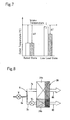
- the refrigerant temperature at the outlet of the paths 7a and 8A becomes lower (refer to ⁇ T in Fig. 7 ) at the outlet of the paths 7b and 8B in which the flow velocity is low since there is no margin in heat exchange capacity.
- the outlet of paths 7a and 8A in which the flow velocity is high is shown by the blank backgrounds
- the outlet of paths 7b and 8B in which the flow velocity is low is shown by the shadowed backgrounds.
- a refrigerant flow amount regulation valve V 1 is arranged in the outlet of the paths 7b and 8B at which the temperature becomes low at least when the load is low.
- the temperature (dryness) at the outlet of the paths 7a and 8A is matched with the temperature (dryness) at the outlet of the paths 7b and 8B (for example, refer to patent publication 1).
- the paths of high flow velocity are shown by the blank backgrounds, and the paths of low flow velocity are shown by the shadowed backgrounds.
- one aspect of the present invention is an air conditioner including a compressor, a four-way valve, an outdoor heat exchanger, a restriction device, and an indoor heat exchanger provided with a plurality of paths. These members are sequentially connected by a refrigerant pipe to form a refrigerant circuit.
- a flow divider including a plurality of paths is arranged between the indoor heat exchanger, which includes the plurality of paths, and the restriction device.
- a refrigerant flow amount regulation valve is provided for each of the plurality of paths in the flow divider. In a predetermined operation state, more refrigerant is distributed to a predetermined path in which the processing capacity is large and the refrigerant temperature at an outlet of the indoor heat exchanger is high in comparison with other paths.
- the predetermined operation state is an operation state in which the load is low, and in the low load state, an opening is decreased in the refrigerant flow amount regulation valve of the path at which the processing capacity is small and the refrigerant temperature at the outlet of the indoor heat exchanger is low so that a large amount of refrigerant flows to the predetermined path in which the processing capacity is large and the refrigerant temperature at the outlet of the indoor heat exchanger is high.
- the opening of the refrigerant flow amount regulation valve is decreased for the path at which the processing capacity is small and the refrigerant temperature at the outlet of the indoor heat exchanger is low. Further, by distributing more refrigerant to the predetermined path at which there is a margin in the processing capacity and the flow velocity is high, the in-pipe flow velocity of the path increases. Additionally, the difference between the temperature at the outlet of the indoor heat exchanger and the intake temperature increases. As a result, the capacity of the heat exchanger is effectively increased, and the refrigerant capacity is increased.
- the predetermined path is a path in which the flow velocity is high, and in a low load state, an opening of the refrigerant flow amount regulation valve is decreased for a path in which the flow velocity is low so that more refrigerant flows to the path that has a margin in heat exchange capacity and a high flow velocity.
- the refrigerant flow amount regulation valve is closed for a path having a low flow velocity and no margin in the processing capacity so that more refrigerant is distributed to a path that has a margin in the processing capacity and has a high flow velocity. This increases the in-pipe flow velocity of the path.
- the difference between the temperature at the outlet of the indoor heat exchanger and the intake temperature increases. As a result, the capacity of the heat exchanger is effectively increased, and the refrigerant capacity is increased.
- the predetermined operation state is an operation state during a rated load, and in the rated load state, the refrigerant flow amount regulation valve for each path is completely open, and the capacity of the heat exchanger is fully used.
- the refrigerant flow amount regulation valve for each path in an operation state during a rated load, the refrigerant flow amount regulation valve for each path is completely open, and the capacity of the heat exchanger can be fully used.
- Figs. 1 and 2 show the structures of a refrigerant circuit and its flow divider in an air conditioner according to a first embodiment of the present invention
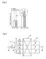
- Fig. 3 shows the operation and effect of such a structure.
- the heat exchanger 26 is broadly divided into two flow velocity regions, low flow velocity portions A and B and high flow velocity portions C and D. Further, the flow divider 6 has two paths.
- the air conditioner includes outdoor equipment 1 and indoor equipment 10.
- the outdoor equipment 1 includes a compressor 2, a four-way valve 3, an outdoor heat exchanger 4, and a restriction device 5.
- the indoor equipment 10 includes a flow divider 6, an inlet 6a for the flow of refrigerant into the flow divider 6, a first branch flow path 7a in the flow divider 6, a second branch flow path 7b in the flow divider 6, an indoor heat exchanger 26, a first path 8A located at the outlet of indoor heat exchanger 26, a second path 8B located at the outlet of the heat exchanger 26, and an expansion valve V.
- These members are connected to a first refrigerant pipe 9A and a second refrigerant pipe 9B to form an irreversible refrigerant circulation circuit as shown in Fig. 1 .
- the expansion valve V and the flow divider 6 are arranged between the indoor heat exchanger 26 and the restriction device 5.
- First and second refrigerant flow amount regulation valves V 1 and V 2 that are electromagnetic valves of which the opening degrees of each are electrically adjustable.
- the valves V 1 and V 2 are respectively arranged in first and second branch flow paths 7a and 7b of the flow divider 6. Under a predetermined operation state, more refrigerant is distributed to the one of the predetermined paths 7a and 7b at which the processing capacity is larger and the temperature at the outlet of the heat exchanger 26 is higher.
- This refrigerant distribution amount control is performed by separately controlling the opening degrees of the first and second refrigerant flow amount regulation valves V 1 and V 2 with, for example, a predetermined control unit including a microcomputer.
- the predetermined operation state is, for example, a low load operation state in which the amount of refrigerant flowing to the refrigerant inlet 6a of the flow divider 6 becomes low.
- a low load state when the second branch flow path 7b extends through a portion 26b in which the flow velocity is low and the first branch flow path 7a extends through a portion 26a in which the flow velocity is high, that is, when the flow velocity is low in the second branch flow path 7b and the flow velocity is high in the first branch flow path 7a, there is, for example, no margin in heat exchange capacity.
- the opening degree is decreased for the refrigerant flow amount regulation valve V 2 that corresponds to the second branch flow path 7b in which the flow velocity is low. Therefore, in comparison with the second branch flow path 7b, more refrigerant flows to the first branch flow path 7a, in which the flow velocity is high and a margin in heat exchange capacity is provided.
- the in-pipe flow velocity becomes high in the first branch flow path 7a in which the flow velocity is high by decreasing the opening degree for the refrigerant flow amount regulation valve V 2 of the second branch flow path 7b in which the flow velocity is low to distribute more refrigerant to the first branch flow path 7a in which the flow velocity is high than the second branch flow path 7b.
- the difference ⁇ T is increased between the temperature at the outlet of the heat exchanger 26 and the intake temperature.
- the capacity of the indoor heat exchanger 26 is increased, and the refrigerant capacity is increased.
- the first branch flow path 7a is shown by the blank backgrounds
- the second branch flow path 7b is shown by the shadowed backgrounds.
- the first and second refrigerant flow amount regulation valves V 1 and V 2 are completely open so that the heat exchange capacity of the heat exchanger 26 is fully used.
- the heat exchange capacity of the indoor heat exchanger 26 for an air conditioner is effectively increased.
- Fig. 4 shows the structure of a flow divider and a heat exchanger for an air conditioner according to a second embodiment of the present invention.
- the indoor heat exchanger 26 of Fig. 6 is divided into two flow velocity regions, low flow velocity portions A and B and high flow velocity portions C and D, and refrigerant is distributed to the two paths, the first and second branch flow paths 7a and 7b.
- the features of the second embodiment are in the structure that will now be described.
- the flow velocity region of the heat exchanger 26 shown in Fig. 6 is finely divided into, for example, four flow velocity regions, low flow velocity portions A, B, and C and high flow velocity portion D.
- First, second, third, and fourth branch flow paths 7a to 7d are respectively arranged in correspondence with the velocity regions.
- first to fourth refrigerant flow amount regulation valves V 21 to V 24 are respectively arranged in the branch flow paths 7a to 7d.
- the opening degrees are decreased for the first to third refrigerant flow amount regulation valves V 21 to V 23 of the first to third branch flow paths 7a to 7c in which the flow velocity is low and no margin is provided for the processing capacity. Further, more refrigerant is distributed to the fourth branch flow path 7d in which the flow velocity is high and a margin is provided for the processing capacity. This increases the in-pipe flow velocity of the fourth branch flow path 7d and increases the difference between the temperature at the outlet of the indoor heat exchanger 26 and the intake temperature.
- the capacity of the indoor heat exchanger 26 is increased, and the refrigerant capacity is increased.
- the refrigerant flow amount regulation valves V 21 to V 24 are completely open so that the capacity of the heat exchanger 26 is fully used.
Landscapes
- Engineering & Computer Science (AREA)
- Physics & Mathematics (AREA)
- Mechanical Engineering (AREA)
- Thermal Sciences (AREA)
- General Engineering & Computer Science (AREA)
- Chemical & Material Sciences (AREA)
- Combustion & Propulsion (AREA)
- Air Conditioning Control Device (AREA)
- Devices For Conveying Motion By Means Of Endless Flexible Members (AREA)
Abstract
Description
- The present invention relates to an air conditioner, and more particularly, to an air conditioner including a flow divider for appropriately dividing the flow of refrigerant to a plurality of paths in an indoor heat exchanger of the air conditioner.
-
Fig. 5 shows the structure of a typical wall-mount air conditioner (indoor equipment) 21 employing across flow fan 29. As shown inFig. 5 , theair conditioner 21 includes amain body casing 20 having an upper surface in which a firstair intake grille 23 is formed and a front surface upper portion in which a secondair intake grille 24 is formed. Themain body casing 20 also has anair discharge port 25 arranged in a lower corner of the front surface. - An
air passage 27 extends from theair intake grilles air discharge port 25 in themain body casing 20. Anindoor heat exchanger 26, which has a V-shaped cross-section so as to face toward the first and secondair intake grilles air passage 27. Theindoor heat exchanger 26 is a lambda-type heat exchanger. Across flow fan 29, atongue 22, and ascroll 30 are arranged in the downstream region of theair passage 27. Thecross flow fan 29 has an impeller (fan rotor) 29a, which is rotated in the direction of the arrow shown inFig. 5 and which is arranged in an opening 22a of thetongue 22 and opening 30a of thescroll 30. - The
tongue 22 is located at a position facing toward the secondair intake grill 24 and has a predetermined length along the outer circumference of the impeller (fan rotor) 29a in thecross flow fan 29. - The
tongue 22 has a lower portion that is continuous with anair flow guide 22b, which also serves as a drain pan and which is arranged below theindoor heat exchanger 26. Theair flow guide 22b has a downstream portion, which extends toward theair discharge port 25 together with adownstream portion 30b of thescroll 30 and which forms an air discharge passage 28 having a diffuser structure as shown in the drawing. As a result, the flow of air generated by the impeller (fan rotor) 29a of thecross flow fan 29 is efficiently discharged from theair discharge port 25. - A
stream deflection plate 31 is arranged in the air discharge passage 28 between thescroll 30 and theair flow guide 22b, which is located at the lower portion of thetongue 22. - The
tongue 22 is shaped as shown inFig. 5 . The flow of air from theindoor heat exchanger 26 to theair discharge port 25 via the impeller (fan rotor) 29a of thecross flow fan 29 is curved in its entirety along the rotation direction of the impeller (fan rotor) 29a and discharged in a direction perpendicular to the rotation axis of the impeller (fan rotor) 29a. Then, the flow of air is curved along the air discharge passage 28 toward theair discharge port 25 and discharged out of the front surface of theair conditioner 21. - In the
indoor heat exchanger 26 having such a structure, theheat exchanger 26 was divided into portions A, B, C, and D to analyze the flow velocity distribution. As a result, the flow velocity in portion D, which directly faces toward the secondair intake grille 24, was the highest. The flow velocity was lower than portion D in portion C, which diagonally faces toward the firstair intake grille 23. Further, the flow velocity was lower than portion C in portion B, which is covered by the upper portion of the front surface of themain body casing 20 and thus does not directly receive the flow of air. The flow velocity was lower than portion B in portion A, which is blocked by thetongue 22 from the flow of air. - An
indoor heat exchanger 26 having a plurality of paths in an air conditioner as described above usually includes aflow divider 6 includingbranch flow paths Fig. 6 , to distribute the refrigerant that flows into the main body of theheat exchanger 26 into each path in the main body of theheat exchanger 26. Theflow divider 6 determines the distribution ratio of the refrigerant for thebranch flow paths refrigerant inlet 6a are arranged at the entrance of theflow divider 6. When the load is low, in theindoor heat exchanger 26, thebranch flow path 7a extends through aportion 26a in which the flow velocity is high, and thebranch flow path 7b extends through aportion 26b in which the flow velocity is low. - Accordingly, as expressed by the width of the arrows in
Fig. 6 , during rated operation, the refrigerant temperatures become substantially the same at the outlet of thepaths heat exchanger 26. However, in a low load (partial load) state in which the amount of refrigerant decreases, the flow velocity distribution that differs in correspondence with the position of the air flow passage in theheat exchanger 26 has affects that result in problems that will now be described. For example, as shown in the graph ofFig. 7 , the refrigerant temperature increases at the outlet of thepaths paths Fig. 7 ) at the outlet of thepaths Fig. 7 , the outlet ofpaths paths - As one solution for solving this problem, a refrigerant flow amount regulation valve V1 is arranged in the outlet of the
paths Fig. 9 , the temperature (dryness) at the outlet of thepaths paths Fig. 9 , the paths of high flow velocity are shown by the blank backgrounds, and the paths of low flow velocity are shown by the shadowed backgrounds. - Patent Publication 1: Japanese Laid-Open Patent Publication No.
5-118682 - However, with such a structure, particularly when the proportions of the shadowed portions in
Figs. 6 and8 are increased to increase the dryness, the capacity in a low load state does not increase that much. - It is an object of the present invention to provide an air conditioner that increases the heat exchanging capacity by appropriately controlling the refrigerant drift between the paths of a flow divider that corresponds to the heat exchanger of an air conditioner.
- To achieve the above object, one aspect of the present invention is an air conditioner including a compressor, a four-way valve, an outdoor heat exchanger, a restriction device, and an indoor heat exchanger provided with a plurality of paths. These members are sequentially connected by a refrigerant pipe to form a refrigerant circuit. A flow divider including a plurality of paths is arranged between the indoor heat exchanger, which includes the plurality of paths, and the restriction device. A refrigerant flow amount regulation valve is provided for each of the plurality of paths in the flow divider. In a predetermined operation state, more refrigerant is distributed to a predetermined path in which the processing capacity is large and the refrigerant temperature at an outlet of the indoor heat exchanger is high in comparison with other paths.
- With this structure, in a predetermined operation state, more refrigerant is positively distributed to paths having margins in processing capacities to increase the in-pipe flow velocity in such paths. Further, the difference between the temperature at the outlet of the indoor heat exchanger and the intake temperature increases. This increases the capacity of the indoor heat exchanger and increases the refrigerant capacity.
- Preferably, the predetermined operation state is an operation state in which the load is low, and in the low load state, an opening is decreased in the refrigerant flow amount regulation valve of the path at which the processing capacity is small and the refrigerant temperature at the outlet of the indoor heat exchanger is low so that a large amount of refrigerant flows to the predetermined path in which the processing capacity is large and the refrigerant temperature at the outlet of the indoor heat exchanger is high.
- In this structure, when the load is low and the entire refrigerant flow amount decreases, the opening of the refrigerant flow amount regulation valve is decreased for the path at which the processing capacity is small and the refrigerant temperature at the outlet of the indoor heat exchanger is low. Further, by distributing more refrigerant to the predetermined path at which there is a margin in the processing capacity and the flow velocity is high, the in-pipe flow velocity of the path increases. Additionally, the difference between the temperature at the outlet of the indoor heat exchanger and the intake temperature increases. As a result, the capacity of the heat exchanger is effectively increased, and the refrigerant capacity is increased.
- Preferably, the predetermined path is a path in which the flow velocity is high, and in a low load state, an opening of the refrigerant flow amount regulation valve is decreased for a path in which the flow velocity is low so that more refrigerant flows to the path that has a margin in heat exchange capacity and a high flow velocity. With this structure, the refrigerant flow amount regulation valve is closed for a path having a low flow velocity and no margin in the processing capacity so that more refrigerant is distributed to a path that has a margin in the processing capacity and has a high flow velocity. This increases the in-pipe flow velocity of the path. Additionally, the difference between the temperature at the outlet of the indoor heat exchanger and the intake temperature increases. As a result, the capacity of the heat exchanger is effectively increased, and the refrigerant capacity is increased.
- Preferably, the predetermined operation state is an operation state during a rated load, and in the rated load state, the refrigerant flow amount regulation valve for each path is completely open, and the capacity of the heat exchanger is fully used. With this structure, in an operation state during a rated load, the refrigerant flow amount regulation valve for each path is completely open, and the capacity of the heat exchanger can be fully used.
-
-
Fig. 1 is a diagram showing a refrigerant circuit of an air conditioner according to a first embodiment of the present invention; -
Fig. 2 is a diagram showing the operation and structure of a heat exchanger including a plurality of paths and a flow divider corresponding to the paths of the heat exchanger in the indoor equipment of the air conditioner; -
Fig. 3 is a graph showing the comparison of temperatures at the outlet of the indoor equipment heat exchanger resulting from the flow divider shown inFig. 2 in a rated state and a low load state; -
Fig. 4 is a diagram showing the operation and structure of a heat exchanger including a plurality of paths and a flow divider corresponding to the paths of the heat exchanger in the indoor equipment of an air conditioner according to a second embodiment of the present invention; -
Fig. 5 is a diagram showing the structure of the indoor equipment for an air conditioner of the prior art; -
Fig. 6 is a diagram showing the operation and structure of a heat exchanger including a plurality of paths and a flow divider corresponding to the paths of the heat exchanger in the indoor equipment of an air conditioner: -
Fig. 7 is a graph showing the comparison of temperatures at the outlet of the indoor equipment heat exchanger resulting from the flow divider shown inFig. 6 in a rated state and a low load state; -
Fig. 8 is a diagram showing the operation and structure of a heat exchanger including a plurality of paths and a flow divider corresponding to the paths of the heat exchanger in the indoor equipment of a prior art air conditioner which has been modified to cope with the outlet temperature problems; and -
Fig. 9 is a graph showing the comparison of temperatures at the outlet of the indoor equipment heat exchanger resulting from the flow divider shown inFig. 8 in a rated state and a low load state. -
Figs. 1 and 2 show the structures of a refrigerant circuit and its flow divider in an air conditioner according to a first embodiment of the present invention, andFig. 3 shows the operation and effect of such a structure. To facilitate description, in the structure of this embodiment, theheat exchanger 26 is broadly divided into two flow velocity regions, low flow velocity portions A and B and high flow velocity portions C and D. Further, theflow divider 6 has two paths. - As shown in
Fig. 1 , the air conditioner includesoutdoor equipment 1 andindoor equipment 10. Theoutdoor equipment 1 includes acompressor 2, a four-way valve 3, an outdoor heat exchanger 4, and arestriction device 5. Theindoor equipment 10 includes aflow divider 6, aninlet 6a for the flow of refrigerant into theflow divider 6, a firstbranch flow path 7a in theflow divider 6, a secondbranch flow path 7b in theflow divider 6, anindoor heat exchanger 26, afirst path 8A located at the outlet ofindoor heat exchanger 26, asecond path 8B located at the outlet of theheat exchanger 26, and an expansion valve V. These members are connected to afirst refrigerant pipe 9A and a secondrefrigerant pipe 9B to form an irreversible refrigerant circulation circuit as shown inFig. 1 . - The expansion valve V and the
flow divider 6 are arranged between theindoor heat exchanger 26 and therestriction device 5. First and second refrigerant flow amount regulation valves V1 and V2 that are electromagnetic valves of which the opening degrees of each are electrically adjustable. The valves V1 and V2 are respectively arranged in first and secondbranch flow paths flow divider 6. Under a predetermined operation state, more refrigerant is distributed to the one of thepredetermined paths heat exchanger 26 is higher. This refrigerant distribution amount control is performed by separately controlling the opening degrees of the first and second refrigerant flow amount regulation valves V1 and V2 with, for example, a predetermined control unit including a microcomputer. - In this case, the predetermined operation state is, for example, a low load operation state in which the amount of refrigerant flowing to the
refrigerant inlet 6a of theflow divider 6 becomes low. For example, as shown inFig. 2 , in a low load state, when the secondbranch flow path 7b extends through aportion 26b in which the flow velocity is low and the firstbranch flow path 7a extends through aportion 26a in which the flow velocity is high, that is, when the flow velocity is low in the secondbranch flow path 7b and the flow velocity is high in the firstbranch flow path 7a, there is, for example, no margin in heat exchange capacity. Thus, the opening degree is decreased for the refrigerant flow amount regulation valve V2 that corresponds to the secondbranch flow path 7b in which the flow velocity is low. Therefore, in comparison with the secondbranch flow path 7b, more refrigerant flows to the firstbranch flow path 7a, in which the flow velocity is high and a margin in heat exchange capacity is provided. - In this manner, in a low load state in which the entire refrigerant flow amount decreases, the in-pipe flow velocity becomes high in the first
branch flow path 7a in which the flow velocity is high by decreasing the opening degree for the refrigerant flow amount regulation valve V2 of the secondbranch flow path 7b in which the flow velocity is low to distribute more refrigerant to the firstbranch flow path 7a in which the flow velocity is high than the secondbranch flow path 7b. Further, as shown by the graph inFig. 3 , the difference ΔT is increased between the temperature at the outlet of theheat exchanger 26 and the intake temperature. As a result, the capacity of theindoor heat exchanger 26 is increased, and the refrigerant capacity is increased. In the graph ofFig. 3 , the firstbranch flow path 7a is shown by the blank backgrounds, and the secondbranch flow path 7b is shown by the shadowed backgrounds. - In a rated load state, the first and second refrigerant flow amount regulation valves V1 and V2 are completely open so that the heat exchange capacity of the
heat exchanger 26 is fully used. As a result, in the present embodiment, in comparison with the prior art structure that merely equalizes the temperatures at the outlets of thepaths indoor heat exchanger 26, the heat exchange capacity of theindoor heat exchanger 26 for an air conditioner is effectively increased. -
Fig. 4 shows the structure of a flow divider and a heat exchanger for an air conditioner according to a second embodiment of the present invention. In the structure of the first embodiment, to facilitate description, for example, theindoor heat exchanger 26 ofFig. 6 is divided into two flow velocity regions, low flow velocity portions A and B and high flow velocity portions C and D, and refrigerant is distributed to the two paths, the first and secondbranch flow paths heat exchanger 26 shown inFig. 6 is finely divided into, for example, four flow velocity regions, low flow velocity portions A, B, and C and high flow velocity portion D. First, second, third, and fourthbranch flow paths 7a to 7d are respectively arranged in correspondence with the velocity regions. In the same manner as the first embodiment, first to fourth refrigerant flow amount regulation valves V21 to V24 are respectively arranged in thebranch flow paths 7a to 7d. - In this manner, in a low load state in which at least the entire refrigerant flow amount is low, even when using the first to fourth
branch flow paths 7a to 7d, the opening degrees are decreased for the first to third refrigerant flow amount regulation valves V21 to V23 of the first to thirdbranch flow paths 7a to 7c in which the flow velocity is low and no margin is provided for the processing capacity. Further, more refrigerant is distributed to the fourthbranch flow path 7d in which the flow velocity is high and a margin is provided for the processing capacity. This increases the in-pipe flow velocity of the fourthbranch flow path 7d and increases the difference between the temperature at the outlet of theindoor heat exchanger 26 and the intake temperature. As a result, the capacity of theindoor heat exchanger 26 is increased, and the refrigerant capacity is increased. In a rated load state, the refrigerant flow amount regulation valves V21 to V24 are completely open so that the capacity of theheat exchanger 26 is fully used.
Claims (4)
- An air conditioner including a compressor, a four-way valve, an outdoor heat exchanger, a restriction device, and an indoor heat exchanger provided with a plurality of paths, wherein the four-way valve, outdoor heat exchanger, restriction device, and indoor heat exchanger are sequentially connected by a refrigerant pipe to form a refrigerant circuit, with a flow divider including a plurality of paths being arranged between the indoor heat exchanger, which includes the plurality of paths, and the restriction device, the air conditioner being characterized by:a refrigerant flow amount regulation valve provided for each of the plurality of paths in the flow divider, wherein in a predetermined operation state, more refrigerant is distributed to a predetermined path in which the processing capacity is large and the refrigerant temperature at an outlet of the indoor heat exchanger is high in comparison with other paths.
- The air conditioner according to claim 1, being characterized in that the predetermined operation state is an operation state in which the load is low, and in the low load state, an opening is decreased in the refrigerant flow amount regulation valve for the path at which the processing capacity is small and the refrigerant temperature at the outlet of the indoor heat exchanger is low so that a large amount of refrigerant flows to the predetermined path in which the processing capacity is large and the refrigerant temperature at the outlet of the indoor heat exchanger is high.
- The air conditioner according to claim 1, being characterized in that the predetermined path is a path in which the flow velocity is high, and in a low load state, an opening is decreased in the refrigerant flow amount regulation valve for a path in which the flow velocity is low so that more refrigerant flows to the path that has a margin in heat exchange capacity and a high flow velocity.
- The air conditioner according to claim 1, being characterized in that the predetermined operation state is an operation state during a rated load, and in the rated load state, the refrigerant flow amount regulation valve for each path is completely open, and the capacity of the heat exchanger is fully used.
Applications Claiming Priority (2)
| Application Number | Priority Date | Filing Date | Title |
|---|---|---|---|
| JP2006007578A JP4120680B2 (en) | 2006-01-16 | 2006-01-16 | Air conditioner |
| PCT/JP2007/050476 WO2007081021A1 (en) | 2006-01-16 | 2007-01-16 | Air conditioner |
Publications (2)
| Publication Number | Publication Date |
|---|---|
| EP1975525A1 true EP1975525A1 (en) | 2008-10-01 |
| EP1975525A4 EP1975525A4 (en) | 2014-07-23 |
Family
ID=38256422
Family Applications (1)
| Application Number | Title | Priority Date | Filing Date |
|---|---|---|---|
| EP07706803.9A Withdrawn EP1975525A4 (en) | 2006-01-16 | 2007-01-16 | AIR CONDITIONER |
Country Status (7)
| Country | Link |
|---|---|
| US (1) | US20090025420A1 (en) |
| EP (1) | EP1975525A4 (en) |
| JP (1) | JP4120680B2 (en) |
| KR (1) | KR100973916B1 (en) |
| CN (2) | CN101149097B (en) |
| AU (1) | AU2007205443B2 (en) |
| WO (1) | WO2007081021A1 (en) |
Cited By (8)
| Publication number | Priority date | Publication date | Assignee | Title |
|---|---|---|---|---|
| WO2011072679A1 (en) * | 2009-12-18 | 2011-06-23 | Danfoss A/S | A vapour compression system with split evaporator |
| WO2011072685A1 (en) * | 2009-12-18 | 2011-06-23 | Danfoss A/S | An expansion device unit for a vapour compression system |
| KR101240188B1 (en) * | 2010-09-06 | 2013-03-07 | 한라공조주식회사 | Air conditioner for vehicle |
| EP2878912A1 (en) * | 2013-11-28 | 2015-06-03 | Alfa Laval Corporate AB | System and method for dynamic control of a heat exchanger |
| EP2314957B1 (en) * | 2009-05-14 | 2016-06-29 | Hanon Systems | Multi-evaporation system |
| EP3106773A4 (en) * | 2014-02-10 | 2017-09-13 | Mitsubishi Electric Corporation | Heat pump hot water supply device |
| EP3604974A4 (en) * | 2017-03-27 | 2020-04-22 | Daikin Industries, Ltd. | HEAT EXCHANGER AND REFRIGERATION DEVICE |
| US11415371B2 (en) | 2017-03-27 | 2022-08-16 | Daikin Industries, Ltd. | Heat exchanger and refrigeration apparatus |
Families Citing this family (23)
| Publication number | Priority date | Publication date | Assignee | Title |
|---|---|---|---|---|
| KR100925734B1 (en) * | 2007-08-06 | 2009-11-11 | 엘지전자 주식회사 | Clothes dryer |
| KR100894471B1 (en) * | 2007-08-06 | 2009-04-22 | 엘지전자 주식회사 | Clothes dryer |
| JP5062265B2 (en) * | 2010-02-15 | 2012-10-31 | ダイキン工業株式会社 | Air conditioner |
| JP5747494B2 (en) * | 2010-12-14 | 2015-07-15 | 日産自動車株式会社 | Exhaust heat exchanger |
| US20130186129A1 (en) * | 2012-01-25 | 2013-07-25 | Lg Electronics Inc. | Refrigerator |
| JP5858824B2 (en) * | 2012-03-01 | 2016-02-10 | 三菱電機株式会社 | Multi-type air conditioner |
| KR102025738B1 (en) * | 2012-07-06 | 2019-09-27 | 삼성전자주식회사 | Refrigerator and heat exchanger for the same |
| KR101425043B1 (en) * | 2012-07-26 | 2014-08-01 | 엘지전자 주식회사 | Outdoor heat exchanger |
| KR101384148B1 (en) * | 2012-07-26 | 2014-04-10 | 엘지전자 주식회사 | Air conditioner and method for controling of air conditioner |
| CN102829584A (en) * | 2012-09-04 | 2012-12-19 | 海信科龙电器股份有限公司 | Refrigerating system for air conditioner |
| US10107514B2 (en) * | 2013-08-28 | 2018-10-23 | Mitsubishi Electric Corporation | Air-conditioning apparatus including multiple expansion devices |
| WO2015063853A1 (en) * | 2013-10-29 | 2015-05-07 | 株式会社日立製作所 | Refrigeration cycle and air conditioner |
| US10139143B2 (en) * | 2013-12-17 | 2018-11-27 | Lennox Industries Inc. | Air conditioner with multiple expansion devices |
| KR20160016436A (en) * | 2014-08-05 | 2016-02-15 | 삼성전자주식회사 | Air conditioner |
| CN106016682B (en) * | 2016-06-02 | 2019-01-15 | 青岛海尔空调器有限总公司 | Air conditioner supplying natural wind heat-exchanger rig and its control method, air conditioner supplying natural wind |
| WO2018193518A1 (en) * | 2017-04-18 | 2018-10-25 | 三菱電機株式会社 | Air conditioner |
| JP6882679B2 (en) * | 2017-07-07 | 2021-06-02 | 株式会社椿本チエイン | Tensioner |
| EP3702696A4 (en) | 2017-10-27 | 2020-11-18 | Mitsubishi Electric Corporation | REFRIGERATION CIRCUIT DEVICE |
| CN113091353B (en) * | 2021-03-11 | 2022-12-23 | 青岛海尔空调器有限总公司 | Air conditioner flow divider, control method and control device for air conditioner flow divider |
| CN113531959A (en) * | 2021-06-29 | 2021-10-22 | 青岛海尔空调器有限总公司 | Split flow structure and split flow method of heat exchanger |
| CN114838457B (en) * | 2022-03-16 | 2024-02-20 | 青岛海尔空调器有限总公司 | Control methods, control systems, electronic equipment and media to prevent air conditioners from freezing |
| CN114838458B (en) * | 2022-03-16 | 2024-02-20 | 青岛海尔空调器有限总公司 | Control methods, control systems, electronic equipment and media to prevent air conditioners from freezing |
| CN114812014A (en) * | 2022-04-29 | 2022-07-29 | 青岛海信日立空调系统有限公司 | Heat exchanger and air conditioner |
Family Cites Families (22)
| Publication number | Priority date | Publication date | Assignee | Title |
|---|---|---|---|---|
| AU581569B2 (en) * | 1986-06-06 | 1989-02-23 | Mitsubishi Denki Kabushiki Kaisha | Multiroom air conditioner |
| JPS6334459A (en) * | 1986-07-29 | 1988-02-15 | 株式会社東芝 | Air conditioner |
| JPH0275860A (en) * | 1988-09-09 | 1990-03-15 | Nissin Kogyo Kk | Method and apparatus for preventing compressed refrigerant gas of refrigerating compressor from abnormally overheating |
| JPH03282150A (en) * | 1990-03-30 | 1991-12-12 | Toshiba Corp | Air conditioner and its controlling system |
| DE4015028A1 (en) * | 1990-05-10 | 1992-01-16 | Skf Gmbh | PRE-ADJUSTABLE CLAMPING DEVICE |
| JPH04208363A (en) * | 1990-11-30 | 1992-07-30 | Matsushita Seiko Co Ltd | Heat exchanger distributor |
| JPH05118682A (en) * | 1991-10-25 | 1993-05-14 | Sharp Corp | Air conditioner |
| JPH05280829A (en) * | 1992-03-31 | 1993-10-29 | Matsushita Seiko Co Ltd | Air conditioner |
| US5266067A (en) * | 1992-09-25 | 1993-11-30 | Federal-Mogul Corporation | Self-releasing tensioner |
| JP3060770B2 (en) * | 1993-02-26 | 2000-07-10 | ダイキン工業株式会社 | Refrigeration equipment |
| IN192214B (en) * | 1996-07-19 | 2004-03-20 | Fujitsu General Ltd | |
| EP0930474B1 (en) * | 1997-06-03 | 2005-10-19 | Daikin Industries, Ltd. | Refrigerating plant |
| JP2000179968A (en) * | 1998-12-18 | 2000-06-30 | Fujitsu General Ltd | Refrigeration cycle of air conditioner |
| JP2001227845A (en) * | 2000-02-18 | 2001-08-24 | Fujitsu General Ltd | Air conditioner |
| US6189329B1 (en) * | 2000-04-04 | 2001-02-20 | Venturedyne Limited | Cascade refrigeration system |
| US6343482B1 (en) * | 2000-10-31 | 2002-02-05 | Takeshi Endo | Heat pump type conditioner and exterior unit |
| US6502413B2 (en) * | 2001-04-02 | 2003-01-07 | Carrier Corporation | Combined expansion valve and fixed restriction system for refrigeration cycle |
| KR100437804B1 (en) * | 2002-06-12 | 2004-06-30 | 엘지전자 주식회사 | Multi-type air conditioner for cooling/heating the same time and method for controlling the same |
| US7493775B2 (en) * | 2002-10-30 | 2009-02-24 | Mitsubishi Denki Kabushiki Kaisha | Air conditioner |
| KR100463548B1 (en) * | 2003-01-13 | 2004-12-29 | 엘지전자 주식회사 | Air conditioner |
| JP2005273923A (en) * | 2004-03-23 | 2005-10-06 | Hitachi Home & Life Solutions Inc | Air conditioner |
| JP2005315309A (en) * | 2004-04-28 | 2005-11-10 | Hitachi Home & Life Solutions Inc | Refrigerant flow control valve |
-
2006
- 2006-01-16 JP JP2006007578A patent/JP4120680B2/en not_active Expired - Fee Related
- 2006-12-28 CN CN2006101567452A patent/CN101149097B/en not_active Expired - Fee Related
-
2007
- 2007-01-16 US US12/087,100 patent/US20090025420A1/en not_active Abandoned
- 2007-01-16 EP EP07706803.9A patent/EP1975525A4/en not_active Withdrawn
- 2007-01-16 AU AU2007205443A patent/AU2007205443B2/en not_active Ceased
- 2007-01-16 CN CN2007800017227A patent/CN101360961B/en not_active Expired - Fee Related
- 2007-01-16 WO PCT/JP2007/050476 patent/WO2007081021A1/en not_active Ceased
- 2007-01-16 KR KR1020087013407A patent/KR100973916B1/en not_active Expired - Fee Related
Cited By (13)
| Publication number | Priority date | Publication date | Assignee | Title |
|---|---|---|---|---|
| EP2314957B1 (en) * | 2009-05-14 | 2016-06-29 | Hanon Systems | Multi-evaporation system |
| WO2011072685A1 (en) * | 2009-12-18 | 2011-06-23 | Danfoss A/S | An expansion device unit for a vapour compression system |
| CN102834681A (en) * | 2009-12-18 | 2012-12-19 | 丹福斯有限公司 | An expansion device unit for a vapour compression system |
| CN102834681B (en) * | 2009-12-18 | 2015-04-08 | 丹福斯有限公司 | An expansion device unit for a vapour compression system |
| US9003827B2 (en) | 2009-12-18 | 2015-04-14 | Danfoss A/S | Expansion unit for a vapour compression system |
| WO2011072679A1 (en) * | 2009-12-18 | 2011-06-23 | Danfoss A/S | A vapour compression system with split evaporator |
| KR101240188B1 (en) * | 2010-09-06 | 2013-03-07 | 한라공조주식회사 | Air conditioner for vehicle |
| EP2878912A1 (en) * | 2013-11-28 | 2015-06-03 | Alfa Laval Corporate AB | System and method for dynamic control of a heat exchanger |
| WO2015078661A1 (en) * | 2013-11-28 | 2015-06-04 | Alfa Laval Corporate Ab | System and method for dynamic control of a heat exchanger |
| EP3106773A4 (en) * | 2014-02-10 | 2017-09-13 | Mitsubishi Electric Corporation | Heat pump hot water supply device |
| EP3604974A4 (en) * | 2017-03-27 | 2020-04-22 | Daikin Industries, Ltd. | HEAT EXCHANGER AND REFRIGERATION DEVICE |
| US11262107B2 (en) | 2017-03-27 | 2022-03-01 | Daikin Industries, Ltd. | Heat exchanger having first and second heat exchange units with different refrigerant flow resistances and refrigeration apparatus |
| US11415371B2 (en) | 2017-03-27 | 2022-08-16 | Daikin Industries, Ltd. | Heat exchanger and refrigeration apparatus |
Also Published As
| Publication number | Publication date |
|---|---|
| AU2007205443B2 (en) | 2010-05-27 |
| AU2007205443A1 (en) | 2007-07-19 |
| CN101360961B (en) | 2012-05-23 |
| WO2007081021A1 (en) | 2007-07-19 |
| CN101149097B (en) | 2011-11-16 |
| JP4120680B2 (en) | 2008-07-16 |
| KR100973916B1 (en) | 2010-08-03 |
| CN101149097A (en) | 2008-03-26 |
| JP2007187420A (en) | 2007-07-26 |
| KR20080071588A (en) | 2008-08-04 |
| CN101360961A (en) | 2009-02-04 |
| US20090025420A1 (en) | 2009-01-29 |
| EP1975525A4 (en) | 2014-07-23 |
Similar Documents
| Publication | Publication Date | Title |
|---|---|---|
| AU2007205443B2 (en) | Air conditioner | |
| CN101375114B (en) | Refrigerant splitting device for heat exchangers for refrigeration installations | |
| EP2618066B1 (en) | Blower for outdoor unit, outdoor unit, and refrigeration cycle device | |
| CN108139089B (en) | Outdoor unit and indoor unit of air conditioner | |
| CN109923348B (en) | Indoor unit of air conditioner and air conditioner | |
| CN103988027B (en) | Conditioner and control method thereof | |
| KR101988034B1 (en) | Air conditioner | |
| KR20180054667A (en) | Air conditioner | |
| KR20180037917A (en) | Air conditioning system | |
| CN111433520B (en) | Heat exchange unit and air conditioner equipped with heat exchange unit | |
| EP3745044B1 (en) | Indoor unit for air conditioner | |
| EP3885667B1 (en) | Indoor unit of air-conditioner | |
| CN112146298B (en) | System and method for unloading a multi-stage compressor | |
| US20250052458A1 (en) | Air conditioner with cross-over refrigerant flow | |
| JP7229392B2 (en) | indoor unit of air conditioner | |
| CN222703410U (en) | Duct machine | |
| CN114279002A (en) | Air conditioning device, control method and combined air conditioning unit | |
| KR101703670B1 (en) | Air conditioner for vehicle | |
| CN117190305A (en) | Air conditioner and control method thereof | |
| JP2005321109A (en) | Air conditioner indoor unit |
Legal Events
| Date | Code | Title | Description |
|---|---|---|---|
| PUAI | Public reference made under article 153(3) epc to a published international application that has entered the european phase |
Free format text: ORIGINAL CODE: 0009012 |
|
| 17P | Request for examination filed |
Effective date: 20080626 |
|
| AK | Designated contracting states |
Kind code of ref document: A1 Designated state(s): AT BE BG CH CY CZ DE DK EE ES FI FR GB GR HU IE IS IT LI LT LU LV MC NL PL PT RO SE SI SK TR |
|
| DAX | Request for extension of the european patent (deleted) | ||
| A4 | Supplementary search report drawn up and despatched |
Effective date: 20140625 |
|
| RIC1 | Information provided on ipc code assigned before grant |
Ipc: F25B 1/00 20060101ALI20140618BHEP Ipc: F24F 1/00 20110101ALI20140618BHEP Ipc: F25B 41/00 20060101AFI20140618BHEP Ipc: F25B 41/04 20060101ALI20140618BHEP Ipc: F25B 13/00 20060101ALI20140618BHEP Ipc: F24F 11/02 20060101ALI20140618BHEP Ipc: F25B 5/02 20060101ALI20140618BHEP |
|
| 17Q | First examination report despatched |
Effective date: 20160211 |
|
| STAA | Information on the status of an ep patent application or granted ep patent |
Free format text: STATUS: THE APPLICATION IS DEEMED TO BE WITHDRAWN |
|
| 18D | Application deemed to be withdrawn |
Effective date: 20160622 |