EP1975512A2 - Flammrohre mit prallgekühlten Zündern und Zündrohre für die verbesserte Kühlung der Zünder - Google Patents
Flammrohre mit prallgekühlten Zündern und Zündrohre für die verbesserte Kühlung der Zünder Download PDFInfo
- Publication number
- EP1975512A2 EP1975512A2 EP08103173A EP08103173A EP1975512A2 EP 1975512 A2 EP1975512 A2 EP 1975512A2 EP 08103173 A EP08103173 A EP 08103173A EP 08103173 A EP08103173 A EP 08103173A EP 1975512 A2 EP1975512 A2 EP 1975512A2
- Authority
- EP
- European Patent Office
- Prior art keywords
- igniter
- combustor
- fuel
- supporting ring
- channels
- Prior art date
- Legal status (The legal status is an assumption and is not a legal conclusion. Google has not performed a legal analysis and makes no representation as to the accuracy of the status listed.)
- Granted
Links
- 238000001816 cooling Methods 0.000 title claims abstract description 20
- 239000000446 fuel Substances 0.000 claims abstract description 71
- 238000002485 combustion reaction Methods 0.000 claims abstract description 33
- 239000000203 mixture Substances 0.000 claims abstract description 10
- 238000004891 communication Methods 0.000 claims description 3
- 239000012530 fluid Substances 0.000 claims description 3
- 230000000717 retained effect Effects 0.000 claims description 2
- 239000007789 gas Substances 0.000 description 7
- 230000002411 adverse Effects 0.000 description 3
- 238000007789 sealing Methods 0.000 description 3
- 230000008878 coupling Effects 0.000 description 2
- 238000010168 coupling process Methods 0.000 description 2
- 238000005859 coupling reaction Methods 0.000 description 2
- 239000000463 material Substances 0.000 description 2
- 230000002829 reductive effect Effects 0.000 description 2
- 230000008646 thermal stress Effects 0.000 description 2
- 239000000853 adhesive Substances 0.000 description 1
- 230000001070 adhesive effect Effects 0.000 description 1
- 230000004888 barrier function Effects 0.000 description 1
- 238000007865 diluting Methods 0.000 description 1
- 238000009826 distribution Methods 0.000 description 1
- 230000000694 effects Effects 0.000 description 1
- 230000002452 interceptive effect Effects 0.000 description 1
- 238000004519 manufacturing process Methods 0.000 description 1
- 230000007246 mechanism Effects 0.000 description 1
- 238000000034 method Methods 0.000 description 1
- 230000036961 partial effect Effects 0.000 description 1
- 230000035945 sensitivity Effects 0.000 description 1
- 230000035882 stress Effects 0.000 description 1
- 230000001052 transient effect Effects 0.000 description 1
- 238000003466 welding Methods 0.000 description 1
Images

Classifications
-
- F—MECHANICAL ENGINEERING; LIGHTING; HEATING; WEAPONS; BLASTING
- F23—COMBUSTION APPARATUS; COMBUSTION PROCESSES
- F23R—GENERATING COMBUSTION PRODUCTS OF HIGH PRESSURE OR HIGH VELOCITY, e.g. GAS-TURBINE COMBUSTION CHAMBERS
- F23R3/00—Continuous combustion chambers using liquid or gaseous fuel
- F23R3/02—Continuous combustion chambers using liquid or gaseous fuel characterised by the air-flow or gas-flow configuration
- F23R3/04—Air inlet arrangements
-
- F—MECHANICAL ENGINEERING; LIGHTING; HEATING; WEAPONS; BLASTING
- F02—COMBUSTION ENGINES; HOT-GAS OR COMBUSTION-PRODUCT ENGINE PLANTS
- F02C—GAS-TURBINE PLANTS; AIR INTAKES FOR JET-PROPULSION PLANTS; CONTROLLING FUEL SUPPLY IN AIR-BREATHING JET-PROPULSION PLANTS
- F02C7/00—Features, components parts, details or accessories, not provided for in, or of interest apart form groups F02C1/00 - F02C6/00; Air intakes for jet-propulsion plants
- F02C7/26—Starting; Ignition
- F02C7/264—Ignition
-
- F—MECHANICAL ENGINEERING; LIGHTING; HEATING; WEAPONS; BLASTING
- F23—COMBUSTION APPARATUS; COMBUSTION PROCESSES
- F23R—GENERATING COMBUSTION PRODUCTS OF HIGH PRESSURE OR HIGH VELOCITY, e.g. GAS-TURBINE COMBUSTION CHAMBERS
- F23R3/00—Continuous combustion chambers using liquid or gaseous fuel
- F23R3/002—Wall structures
-
- F—MECHANICAL ENGINEERING; LIGHTING; HEATING; WEAPONS; BLASTING
- F23—COMBUSTION APPARATUS; COMBUSTION PROCESSES
- F23R—GENERATING COMBUSTION PRODUCTS OF HIGH PRESSURE OR HIGH VELOCITY, e.g. GAS-TURBINE COMBUSTION CHAMBERS
- F23R3/00—Continuous combustion chambers using liquid or gaseous fuel
- F23R3/02—Continuous combustion chambers using liquid or gaseous fuel characterised by the air-flow or gas-flow configuration
- F23R3/04—Air inlet arrangements
- F23R3/06—Arrangement of apertures along the flame tube
-
- F—MECHANICAL ENGINEERING; LIGHTING; HEATING; WEAPONS; BLASTING
- F23—COMBUSTION APPARATUS; COMBUSTION PROCESSES
- F23R—GENERATING COMBUSTION PRODUCTS OF HIGH PRESSURE OR HIGH VELOCITY, e.g. GAS-TURBINE COMBUSTION CHAMBERS
- F23R3/00—Continuous combustion chambers using liquid or gaseous fuel
- F23R3/42—Continuous combustion chambers using liquid or gaseous fuel characterised by the arrangement or form of the flame tubes or combustion chambers
- F23R3/60—Support structures; Attaching or mounting means
-
- F—MECHANICAL ENGINEERING; LIGHTING; HEATING; WEAPONS; BLASTING
- F05—INDEXING SCHEMES RELATING TO ENGINES OR PUMPS IN VARIOUS SUBCLASSES OF CLASSES F01-F04
- F05D—INDEXING SCHEME FOR ASPECTS RELATING TO NON-POSITIVE-DISPLACEMENT MACHINES OR ENGINES, GAS-TURBINES OR JET-PROPULSION PLANTS
- F05D2260/00—Function
- F05D2260/20—Heat transfer, e.g. cooling
- F05D2260/201—Heat transfer, e.g. cooling by impingement of a fluid
-
- F—MECHANICAL ENGINEERING; LIGHTING; HEATING; WEAPONS; BLASTING
- F23—COMBUSTION APPARATUS; COMBUSTION PROCESSES
- F23R—GENERATING COMBUSTION PRODUCTS OF HIGH PRESSURE OR HIGH VELOCITY, e.g. GAS-TURBINE COMBUSTION CHAMBERS
- F23R2900/00—Special features of, or arrangements for continuous combustion chambers; Combustion processes therefor
- F23R2900/00012—Details of sealing devices
-
- F—MECHANICAL ENGINEERING; LIGHTING; HEATING; WEAPONS; BLASTING
- F23—COMBUSTION APPARATUS; COMBUSTION PROCESSES
- F23R—GENERATING COMBUSTION PRODUCTS OF HIGH PRESSURE OR HIGH VELOCITY, e.g. GAS-TURBINE COMBUSTION CHAMBERS
- F23R2900/00—Special features of, or arrangements for continuous combustion chambers; Combustion processes therefor
- F23R2900/03044—Impingement cooled combustion chamber walls or subassemblies
-
- Y—GENERAL TAGGING OF NEW TECHNOLOGICAL DEVELOPMENTS; GENERAL TAGGING OF CROSS-SECTIONAL TECHNOLOGIES SPANNING OVER SEVERAL SECTIONS OF THE IPC; TECHNICAL SUBJECTS COVERED BY FORMER USPC CROSS-REFERENCE ART COLLECTIONS [XRACs] AND DIGESTS
- Y02—TECHNOLOGIES OR APPLICATIONS FOR MITIGATION OR ADAPTATION AGAINST CLIMATE CHANGE
- Y02T—CLIMATE CHANGE MITIGATION TECHNOLOGIES RELATED TO TRANSPORTATION
- Y02T50/00—Aeronautics or air transport
- Y02T50/60—Efficient propulsion technologies, e.g. for aircraft
Definitions
- the present invention generally relates to combustors for gas turbine engines, and more particularly relates to combustors with impingement cooled igniters and igniter tubes for improved cooling of igniters.
- Combustors are used to ignite and bum fuel and air mixtures in gas turbine engines.
- Known combustors include inner and outer liners that define an annular combustion chamber in which the fuel and air mixtures are combusted.
- the inner and outer liners are spaced radially inwardly from a combustor casing such that inner and outer passageways are defined between the respective inner and outer liners and the combustor casing.
- Fuel igniters extend through the combustor casing and the outer passageway, and are coupled to the outer liner by igniter tubes attached to the combustor liner. More specifically, the fuel igniter tubes secure and maintain the igniters in alignment relative to the combustion chamber as well as provide a sealing interface for the igniter between the outer passageway and the combustion chamber.
- Cooling the igniter particularly the tip portion of the igniter closest to the combustion process, presents challenges.
- Some conventional igniters include a plurality of longitudinal slots extending down the length of the igniter to channel cooling air to the vicinity of the tip portion of the igniter.
- this arrangement is not very efficient because it requires a relatively large amount of cooling air to sufficiently cool the tip portion of the igniter.
- the large amount of air required to effectively cool the tip portion of the igniter in this manner may adversely impact the combustion conditions within the combustion chamber.
- a large amount of cooling air may have a perturbative effect on the ignition process, gaseous emissions, and the temperature distribution of hot gases entering the turbine.
- the quantity and manner in which cooling air is admitted into the combustor may result in a barrier formed around the igniter that prevents fuel from reaching the tip portion of the igniter. This can additionally reduce the effectiveness of the igniter for igniting the fuel and air mixture. Moreover, excess cooling air can disrupt the liner cooling film and result in local hot spots immediately downstream of the igniter in the combustor liner.
- a combustor for a gas turbine engine is provided in accordance with an exemplary embodiment of the present invention.
- the combustor includes an inner liner; an outer liner circumscribing the inner liner and forming a combustion chamber with the inner liner; a fuel igniter comprising a tip portion configured to ignite an air and fuel mixture in the combustion chamber; and an igniter tube coupling the fuel igniter to the outer liner, the igniter tube having a plurality of channels configured to direct cooling air toward the tip portion of the fuel igniter.
- the igniter tube for positioning a fuel igniter with respect to an outer liner of a combustor is provided in accordance with an exemplary embodiment of the present invention.
- the igniter tube includes an igniter boss having a first end portion for receiving the fuel igniter; a second end portion for coupling the igniter tube to the outer liner; a plurality of channels arranged between the first end portion and the second end portion for directing air toward a tip portion of the fuel igniter.
- An igniter tube is provided in accordance with an exemplary embodiment of the present invention for mounting a fuel igniter to an outer liner of a combustor.
- the igniter tube includes an igniter boss defining a first plurality of holes and configured to be mounted on the annular outer liner; a supporting ring coupled to the igniter boss and defining a second plurality of holes in fluid communication with the first plurality of holes to form a plurality of channels.
- the plurality of channels is configured to direct cooling air onto an igniter tip of the fuel igniter.
- the igniter tube further includes a grommet supported by the supporting ring and configured to receive the fuel igniter.
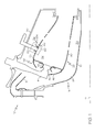
- FIG. 1 is a cross-sectional view of a combustor for a gas turbine engine in accordance with an exemplary embodiment of the present invention.
- FIG. 2 is an enlarged isometric cross-sectional view of an igniter and igniter tube suitable for use in the combustor of FIG. 1 in accordance with an exemplary embodiment of the present invention.
- FIG. 1 is a cross-sectional view of a combustor 14 for a gas turbine engine in accordance with an exemplary embodiment of the present invention.
- the depicted combustor 14 is an annular combustor, any other type of combustor, such as a can combustor, can be provided.
- the combustor 14 can form part of, for example, an auxiliary power unit for an aircraft or a propulsion system for an aircraft.
- the combustor 14 comprises an inner case 18 that extends annularly about a central axis 17 of the combustor 14 and an outer case 20 concentrically arranged with respect to the inner case 18.
- the inner and outer cases 18 and 20 define an annular pressure vessel 24.
- the combustor 14 further includes an inner liner 30 and an outer liner 28 circumscribing the inner liner 30 within the annular pressure vessel 24.
- the outer liner 28 and the inner liner 30 define an annular combustion chamber 32.
- the outer and inner liners 28 and 30 cooperate with outer and inner cases 18 and 20 to define respective outer and inner air passageways 34 and 36.
- the combustor 14 includes a front-end assembly 38 comprising an annularly extending shroud 40, at least one fuel injector 44, and at least one fuel injector guide 46.
- a front-end assembly 38 comprising an annularly extending shroud 40, at least one fuel injector 44, and at least one fuel injector guide 46.
- One fuel injector 44 and one fuel injector guide 46 are shown in the partial cross-sectional view of FIG. 1 , although it is appreciated that more fuel injectors and fuel injector guides may be disposed about central axis 17 in within the combustor 14.
- the fuel injector 44 may also be coupled with a secondary air swirler (not shown) as is typical practice in gas turbine combustors.
- the shroud 40 extends between and is secured to the forwardmost ends of the outer and inner liners 28 and 30.
- the shroud 40 includes at least one shroud port 48 that accommodates the fuel injector 44 and introduces air into the forward end of the combustion chamber 32.
- the fuel injector 44 is secured to the outer case 20 and projects through the shroud port 48.
- the fuel injector 44 introduces a swirling, intimately blended fuel-air mixture that supports combustion in the combustion chamber 32.
- a fuel igniter 62 extends through the outer case 20 and the outer passageway 34, and is coupled to the outer liner 28. It will be appreciated that more than one fuel igniter 62 can be provided in the combustor 14, although only one is illustrated in FIG. 1 .
- the fuel igniter 62 is arranged downstream from the fuel injector 44 and is positioned to ignite a fuel and air mixture within the combustion chamber 32.
- the fuel injector 62 is coupled to outer liner 28 by an igniter tube 64. More specifically, the igniter tube 64 is coupled within an opening 66 extending through outer liner 28, such that the igniter tube 64 is concentrically aligned with respect to the opening 66 of the outer liner 28.
- the igniter tube 64 maintains the alignment of the fuel igniter 62 relative to the combustor 14 and provides for a sealing interface between the igniter 62 and igniter tube 64 of the air in the outer passageway 34 and the combustion chamber 32.
- the opening 66 of the outer liner 28 and the igniter tube 64 have substantially circular cross-sectional profiles. The igniter tube 64 is discussed in greater detail below.
- airflow exits a high pressure diffuser and deswirl 12 (partially shown) at a relatively high velocity and is directed into the annular pressure vessel 24 of the combustor 14.
- the airflow enters the combustion chamber 32 through openings in the liners 28 and 30, where it is mixed with fuel from the fuel injector 44, and the airflow is combusted after being ignited by the fuel igniter 62.
- the combusted air exits the combustion chamber 32 and is delivered to a turbine (not shown).
- FIG. 2 is an enlarged isometric cross-sectional view, represented by the dashed box 60 of FIG. 1 , of the igniter tube 64 coupled to the outer liner 28.
- the igniter tube 64 mounts the igniter 62 in the combustor 14, and particularly mounts the igniter 62 such that a tip portion 118 of the igniter 62 is exposed to the fuel and air mixture in the combustion chamber 32.
- the tip portion 118 may be slightly recessed, slightly protuding, or nominally flush with the inner surface of the outer liner 28.
- the igniter tube 64 includes an igniter boss 74, a grommet 76, and a supporting ring 78 extending therebetween.
- the igniter tube 64 will be typically manufactured from materials that are similar to those of the inner and outer liners 28 and 30, which are capable of withstanding the temperatures within the combustion chamber 32.
- the igniter boss 74 mounts the igniter tube 64 to the outer liner 28.
- an outer diameter 82 of the igniter boss 74 is approximately equal to a diameter of the opening 66 of the outer liner 28, and accordingly, the igniter boss 74 is received in close tolerance within opening 66 of the outer liner 28.
- the igniter boss 74 has a substantially circular outer diameter corresponding to a diameter of the opening 66 of the outer liner 28.
- the igniter boss 74 is mounted onto a surface of the outer liner 28.
- the igniter boss 74 may be mounted to an outside surface 29 or an inside surface 27 and may be mounted using adhesive, welding, screws, or any other suitable means for affixing the igniter boss 74 to the outer liner 28 and providing an adequate sealing interface.
- the igniter boss 74 includes a projection 80 that extends outwardly from the combustion chamber 32.
- the igniter boss 74 also includes an opening 84 extending therethrough. In one embodiment, the opening 84 is substantially circular.
- the opening 84 of the igniter boss 74 is sized to receive the supporting ring 78, and the projection 80 supports the supporting ring 78.
- the supporting ring 78 of the igniter tube 64 includes a first portion 79, a second portion 81, a third portion 83, and a fourth portion 85.
- the first portion 79 of the supporting ring 78 is received by and is coupled to the igniter boss 74.
- the second portion 81 extends generally perpendicularly and radially outwardly from the first portion 79.
- the projection 80 of the igniter boss 74 supports the second portion 81 of the supporting ring 78.
- the projection of the igniter boss 74 is directly coupled to the second portion 81 of the supporting ring 78, and thus, the supporting ring 78 may not include a first portion 79.
- the first portion 79 of the supporting ring 78 is mounted to or otherwise coupled directly to the outer liner 28 such that the igniter boss 74 is omitted.
- the third portion 83 of the supporting ring 78 extends generally perpendicularly from the second portion 81.
- the fourth portion 85 extends radially inward from the third portion 83 and is generally parallel to the second portion 81.
- the grommet 76 of the igniter tube 64 includes a receiving ring 100 coupled to an attaching ring 102, which extends radially substantially perpendicular from the receiving ring 100.
- the attaching ring 102 of the grommet 76 extends radially between the second portion 81 and the fourth portion 85 of the supporting ring 100 and is substantially retained therebetween.
- An outside diameter of the receiving ring 100 is less than an inside diameter of the fourth portion 85 of the supporting ring 78.
- the grommet 76 may be able to move laterally with respect to the supporting ring 78 to accommodate manufacturing tolerances and movements during operation.
- the grommet 76 is fixed to the supporting ring 78 not movable laterally relative to the supporting ring 78, or in a further alternate embodiment, the grommet 76 is directly coupled to the igniter boss 74 and the supporting ring 78 is omitted.
- the receiving ring 100 includes a radially divergent portion that defines an opening 106.
- the opening 106 has a diameter 110 at a first end 112 of the receiving ring 100 that is larger than an inside diameter 114 at a second end 116. Accordingly, the attaching ring 102 of the grommet 76 can guide the fuel igniter 62 into the igniter tube 64 such that the tip portion 118 of the igniter tube 64 extends into the combustion chamber 32.
- the igniter tube 64 secures the fuel igniter 62 and maintains the fuel igniter 62 in alignment relative to the combustor 14 ( FIG. 1 ).
- the illustrated embodiment illustrates the supporting ring 78, the grommet 76, and the igniter boss 78 as separate pieces, in an alternate embodiment, one or more of the supporting ring 78, the grommet 76, and the igniter boss 78 can be integral with one another.
- the igniter tube 64 includes a plurality of channels 76 for directing air to the fuel igniter 62.
- the channels 76 are defined by a first plurality of holes 77 and a second plurality of holes 75.
- the projection 80 of the igniter boss 74 includes the first plurality of holes 77 that extend generally perpendicularly through the projection 80.
- the first portion 79 of the supporting ring 78 includes the second plurality of holes 75 that are generally coaxially aligned in fluid communication with the first plurality of holes 77 in the igniter boss 74.
- a portion 103 of the airflow from the combustor 14 flows through the first plurality of holes 77 in the igniter boss 74 and continues through the second plurality of holes 75 in the supporting ring 78. Subsequently, the portion 103 of airflow directly impinges the fuel igniter 62 mounted by the igniter tube 64 and cools the fuel igniter 62.
- the portion 103 of airflow can particularly be directed to, and cool, the tip portion 118 of the fuel igniter 62.
- the channels 76 direct the airflow 103 essentially perpendicularly to the longitudinal axis 104 of the fuel igniter 62, although it can be appreciated that other angles can be provided to cool the igniter tip 118 of the fuel igniter 62.
- Some fuel igniters 62 may have jackets (not shown) completely or partially covering the tip portion 118 of the fuel igniter 62. In these arrangements, the jacket can be at least partially removed to allow access of the cooling air to the tip portion 118 of the fuel igniter 62.
- the holes 75 and 77 that form the channels 76 in the igniter tube 64 can be circular in diameter and circumferentially aligned about the fuel igniter 62.
- the holes 75 in the first portion 79 of the supporting ring 78 and the holes 77 in the igniter boss 74 do not have to be the same size and/or shape.
- one set of holes 75 or 77 can be larger than the other set of holes 77 or 75 to facilitate alignment.
- one of the sets of holes 75 or 77 can be omitted.
- the igniter boss 74 can omit all or portions of the projection 80, and the holes 77 of the supporting ring 78 can form the channels 76.
- the supporting ring 78 can omit all or portions of the first portion 79, and the holes 75 of the igniter boss 74 can form the channels 76.
- the illustrated embodiment of the igniter tube 64 is depicted with three pieces (i.e., the igniter boss 74, the supporting ring 78, and the grommet 76) and two sets of holes 75 and 77, the igniter tube 64 can have any structural arrangement and combination of holes 75 and 77 that enable a portion 103 of airflow to impinge on the tip portion 118 of the fuel igniter 62.
- the channels 76 of the igniter tube 64 can cool the tip portion 118 of the fuel igniter 62 to temperatures less than, for example, 1500°F. In another exemplary embodiment, the channels 76 of the igniter tube 64 can cool the tip portion 118 of the fuel igniter 62 to temperatures such as, for example, 1200°F. Impingement cooling is more effective than conventional mechanisms, such as slot cooling, for cooling the igniter, and therefore, a reduced amount of air can be used to effectively cool the fuel igniter 62. In one exemplary embodiment, the amount of air necessary to cool the fuel igniter 62 in the combustor 14 is one third or one fourth of the amount of air necessary to cool igniters in conventional combustors.
- ten holes 75 are provided in the inner portion of the supporting ring 78 and ten holes 77 are provided in the igniter boss 74.
- the size of the holes 75 and 77 can be, for example, about 0.04 inches (1 millimeter). A greater or fewer number of holes 75 and 77 can be provided, as well as different sizes.
- Different configurations and arrangements of the igniter tube 64 can be provided as necessary in dependence on the desired temperature of the fuel igniter 62 and the sensitivity of the combustor 14 to additional cooling air. Reduced temperatures in the fuel igniter 62 results in lower thermal stresses and improved life in a cost-effective and reliable manner.
Landscapes
- Engineering & Computer Science (AREA)
- Chemical & Material Sciences (AREA)
- Combustion & Propulsion (AREA)
- Mechanical Engineering (AREA)
- General Engineering & Computer Science (AREA)
- Turbine Rotor Nozzle Sealing (AREA)
- Gas Burners (AREA)
Applications Claiming Priority (1)
| Application Number | Priority Date | Filing Date | Title |
|---|---|---|---|
| US11/694,528 US8479490B2 (en) | 2007-03-30 | 2007-03-30 | Combustors with impingement cooled igniters and igniter tubes for improved cooling of igniters |
Publications (3)
| Publication Number | Publication Date |
|---|---|
| EP1975512A2 true EP1975512A2 (de) | 2008-10-01 |
| EP1975512A3 EP1975512A3 (de) | 2017-05-03 |
| EP1975512B1 EP1975512B1 (de) | 2019-01-16 |
Family
ID=39580430
Family Applications (1)
| Application Number | Title | Priority Date | Filing Date |
|---|---|---|---|
| EP08103173.4A Active EP1975512B1 (de) | 2007-03-30 | 2008-03-28 | Flammrohre mit prallgekühlten zündern und zündrohre für die verbesserte kühlung der zünder |
Country Status (3)
| Country | Link |
|---|---|
| US (1) | US8479490B2 (de) |
| EP (1) | EP1975512B1 (de) |
| CA (1) | CA2627881A1 (de) |
Cited By (10)
| Publication number | Priority date | Publication date | Assignee | Title |
|---|---|---|---|---|
| FR2952703A1 (fr) * | 2009-11-19 | 2011-05-20 | Snecma | Guide d'une bougie d'allumage dans une chambre de combustion d'une turbomachine |
| FR2952702A1 (fr) * | 2009-11-19 | 2011-05-20 | Snecma | Guidage d'une bougie d'allumage dans une chambre de combustion |
| FR2952701A1 (fr) * | 2009-11-18 | 2011-05-20 | Snecma | Guidage d'une bougie d'allumage dans une chambre de combustion d'une turbomachine |
| FR2953908A1 (fr) * | 2009-12-16 | 2011-06-17 | Snecma | Guidage d'une bougie dans une chambre de combustion de turbomachine |
| FR2958373A1 (fr) * | 2010-03-31 | 2011-10-07 | Snecma | Chambre de combustion dans une turbomachine |
| WO2012153040A1 (fr) * | 2011-05-10 | 2012-11-15 | Snecma | Dispositif pour le montage d'une bougie d'allumage dans une chambre de combustion de moteur a turbine a gaz |
| FR2988436A1 (fr) * | 2012-03-26 | 2013-09-27 | Snecma | Dispositif de guidage d'une bougie d'allumage |
| WO2014197045A2 (en) | 2013-03-12 | 2014-12-11 | United Technologies Corporation | Active cooling of grommet bosses for a combustor panel of a gas turbine engine |
| EP3062020A1 (de) * | 2015-02-25 | 2016-08-31 | United Technologies Corporation | Zünderposition für eine brennkammer eines gasturbinentriebwerks |
| CN117703597A (zh) * | 2024-02-06 | 2024-03-15 | 中国空气动力研究与发展中心空天技术研究所 | 冲压发动机微通道耐高温引火装置及设计方法、制备方法 |
Families Citing this family (24)
| Publication number | Priority date | Publication date | Assignee | Title |
|---|---|---|---|---|
| FR2927367B1 (fr) * | 2008-02-11 | 2010-05-28 | Snecma | Dispositif de montage d'une bougie d'allumage dans une chambre de combustion de moteur a turbine a gaz |
| FR2952698B1 (fr) * | 2009-11-17 | 2013-09-20 | Snecma | Chambre de combustion avec bougie d'allumage ventilee |
| US8726631B2 (en) * | 2009-11-23 | 2014-05-20 | Honeywell International Inc. | Dual walled combustors with impingement cooled igniters |
| US9157638B2 (en) * | 2012-01-31 | 2015-10-13 | General Electric Company | Adaptor assembly for removable components |
| US9625151B2 (en) * | 2012-09-25 | 2017-04-18 | United Technologies Corporation | Cooled combustor liner grommet |
| KR101265883B1 (ko) * | 2012-11-22 | 2013-05-20 | 에스티엑스중공업 주식회사 | 점화기 결합구조를 구비하는 마이크로 가스터빈 및 그 조립방법 |
| US9863261B2 (en) | 2012-12-29 | 2018-01-09 | United Technologies Corporation | Component retention with probe |
| WO2014112992A1 (en) | 2013-01-16 | 2014-07-24 | United Technologies Corporation | Combustor cooled quench zone array |
| WO2014168654A1 (en) | 2013-03-14 | 2014-10-16 | Rolls-Royce Corporation | Inverted cap igniter tube |
| US9989254B2 (en) * | 2013-06-03 | 2018-06-05 | General Electric Company | Combustor leakage control system |
| DE102013222932A1 (de) * | 2013-11-11 | 2015-05-28 | Rolls-Royce Deutschland Ltd & Co Kg | Gasturbinenbrennkammer mit Schindel zur Durchführung einer Zündkerze |
| EP3077641B1 (de) | 2013-12-06 | 2020-02-12 | United Technologies Corporation | Kühlung einer zünderdurchführung einer brennkammerwand |
| US9803863B2 (en) | 2015-05-13 | 2017-10-31 | Solar Turbines Incorporated | Controlled-leak combustor grommet |
| US10041413B2 (en) * | 2015-06-05 | 2018-08-07 | General Electric Company | Igniter assembly for a gas turbine engine |
| US10738707B2 (en) | 2015-11-09 | 2020-08-11 | General Electric Company | Igniter for a gas turbine engine |
| US10145559B2 (en) | 2015-12-15 | 2018-12-04 | General Electric Company | Gas turbine engine with igniter stack or borescope mount having noncollinear cooling passages |
| US10215419B2 (en) | 2016-07-08 | 2019-02-26 | Pratt & Whitney Canada Corp. | Particulate buildup prevention in ignitor and fuel nozzle bosses |
| US10837640B2 (en) | 2017-03-06 | 2020-11-17 | General Electric Company | Combustion section of a gas turbine engine |
| US10753283B2 (en) * | 2017-03-20 | 2020-08-25 | Pratt & Whitney Canada Corp. | Combustor heat shield cooling hole arrangement |
| US11242804B2 (en) | 2017-06-14 | 2022-02-08 | General Electric Company | Inleakage management apparatus |
| FR3071908B1 (fr) * | 2017-09-29 | 2019-09-20 | Safran Aircraft Engines | Chambre de combustion de turbomachine a geometrie de cheminee fixe |
| FR3096114B1 (fr) * | 2019-05-13 | 2022-10-28 | Safran Aircraft Engines | Chambre de combustion comprenant des moyens de refroidissement d’une zone d’enveloppe annulaire en aval d’une cheminée |
| JP7175298B2 (ja) * | 2020-07-27 | 2022-11-18 | 三菱重工業株式会社 | ガスタービン燃焼器 |
| US20240271785A1 (en) * | 2023-02-15 | 2024-08-15 | Raytheon Technologies Corporation | Cooling combustor wall boss |
Citations (3)
| Publication number | Priority date | Publication date | Assignee | Title |
|---|---|---|---|---|
| EP1424469A2 (de) * | 2002-11-29 | 2004-06-02 | Rolls-Royce Plc | Dichtungsanordnung in einer Brennkammer |
| US20070051110A1 (en) * | 2005-07-05 | 2007-03-08 | General Electric Company | Igniter tube and method of assembling same |
| US20070068166A1 (en) * | 2005-09-29 | 2007-03-29 | Snecma | Device for guiding an element in an orifice in a wall of a turbomachine combustion chamber |
Family Cites Families (20)
| Publication number | Priority date | Publication date | Assignee | Title |
|---|---|---|---|---|
| US2587331A (en) * | 1947-08-08 | 1952-02-26 | Gen Electric | High-frequency electrical heating method and apparatus |
| US2835110A (en) * | 1952-11-21 | 1958-05-20 | Gen Motors Corp | Injector igniter plug |
| US2831993A (en) * | 1956-07-10 | 1958-04-22 | Champion Spark Plug Co | Igniter |
| US3007312A (en) * | 1959-11-23 | 1961-11-07 | Gen Motors Corp | Combustion liner locater |
| BE795529A (fr) * | 1972-02-17 | 1973-06-18 | Gen Electric | Allumeur monte sur un dispositif d'augmentation de la poussee de turboreacteurs et refroidi a l'air |
| US3736748A (en) * | 1972-04-07 | 1973-06-05 | United Aircraft Corp | Spark igniter for combustion chambers |
| US3990834A (en) * | 1973-09-17 | 1976-11-09 | General Electric Company | Cooled igniter |
| US4099373A (en) * | 1977-05-11 | 1978-07-11 | The United States Of America As Represented By The Secretary Of The Air Force | Vented igniter |
| US4141213A (en) * | 1977-06-23 | 1979-02-27 | General Motors Corporation | Pilot flame tube |
| US5001896A (en) * | 1986-02-26 | 1991-03-26 | Hilt Milton B | Impingement cooled crossfire tube assembly in multiple-combustor gas turbine engine |
| US5367869A (en) * | 1993-06-23 | 1994-11-29 | Simmonds Precision Engine Systems | Laser ignition methods and apparatus for combustors |
| US6182436B1 (en) * | 1998-07-09 | 2001-02-06 | Pratt & Whitney Canada Corp. | Porus material torch igniter |
| US6266961B1 (en) * | 1999-10-14 | 2001-07-31 | General Electric Company | Film cooled combustor liner and method of making the same |
| US6557350B2 (en) * | 2001-05-17 | 2003-05-06 | General Electric Company | Method and apparatus for cooling gas turbine engine igniter tubes |
| US6715279B2 (en) * | 2002-03-04 | 2004-04-06 | General Electric Company | Apparatus for positioning an igniter within a liner port of a gas turbine engine |
| US6920762B2 (en) * | 2003-01-14 | 2005-07-26 | General Electric Company | Mounting assembly for igniter in a gas turbine engine combustor having a ceramic matrix composite liner |
| FR2856466B1 (fr) * | 2003-06-20 | 2005-08-26 | Snecma Moteurs | Dispositif d'etancheite de bougie non soude sur la paroi de chambre |
| US7216488B2 (en) * | 2004-07-20 | 2007-05-15 | General Electric Company | Methods and apparatus for cooling turbine engine combustor ignition devices |
| US20100095680A1 (en) * | 2008-10-22 | 2010-04-22 | Honeywell International Inc. | Dual wall structure for use in a combustor of a gas turbine engine |
| US20100212324A1 (en) * | 2009-02-26 | 2010-08-26 | Honeywell International Inc. | Dual walled combustors with impingement cooled igniters |
-
2007
- 2007-03-30 US US11/694,528 patent/US8479490B2/en active Active
-
2008
- 2008-03-28 CA CA002627881A patent/CA2627881A1/en not_active Abandoned
- 2008-03-28 EP EP08103173.4A patent/EP1975512B1/de active Active
Patent Citations (3)
| Publication number | Priority date | Publication date | Assignee | Title |
|---|---|---|---|---|
| EP1424469A2 (de) * | 2002-11-29 | 2004-06-02 | Rolls-Royce Plc | Dichtungsanordnung in einer Brennkammer |
| US20070051110A1 (en) * | 2005-07-05 | 2007-03-08 | General Electric Company | Igniter tube and method of assembling same |
| US20070068166A1 (en) * | 2005-09-29 | 2007-03-29 | Snecma | Device for guiding an element in an orifice in a wall of a turbomachine combustion chamber |
Cited By (24)
| Publication number | Priority date | Publication date | Assignee | Title |
|---|---|---|---|---|
| FR2952701A1 (fr) * | 2009-11-18 | 2011-05-20 | Snecma | Guidage d'une bougie d'allumage dans une chambre de combustion d'une turbomachine |
| US8875484B2 (en) | 2009-11-19 | 2014-11-04 | Snecma | Guide for an ignition plug in a turbomachine combustion chamber |
| FR2952702A1 (fr) * | 2009-11-19 | 2011-05-20 | Snecma | Guidage d'une bougie d'allumage dans une chambre de combustion |
| FR2952703A1 (fr) * | 2009-11-19 | 2011-05-20 | Snecma | Guide d'une bougie d'allumage dans une chambre de combustion d'une turbomachine |
| FR2953908A1 (fr) * | 2009-12-16 | 2011-06-17 | Snecma | Guidage d'une bougie dans une chambre de combustion de turbomachine |
| FR2953909A1 (fr) * | 2009-12-16 | 2011-06-17 | Snecma | Guidage d'une bougie dans une chambre de combustion de turbomachine |
| WO2011080433A3 (fr) * | 2009-12-16 | 2011-09-29 | Snecma | Guidage d'une bougie dans une chambre de combustion de turbomachine |
| CN102695918A (zh) * | 2009-12-16 | 2012-09-26 | 斯奈克玛 | 引导涡轮发动机燃烧室中的火花塞的方法 |
| US9091445B2 (en) | 2009-12-16 | 2015-07-28 | Snecma | Guiding a sparkplug in a turbine engine combustion chamber |
| CN102695918B (zh) * | 2009-12-16 | 2015-04-01 | 斯奈克玛 | 引导涡轮发动机燃烧室中的火花塞的方法 |
| FR2958373A1 (fr) * | 2010-03-31 | 2011-10-07 | Snecma | Chambre de combustion dans une turbomachine |
| US9784186B2 (en) | 2011-05-10 | 2017-10-10 | Snecma | Device for mounting a spark plug in a combustion engine of a gas turbine engine |
| US10247101B2 (en) | 2011-05-10 | 2019-04-02 | Safran Aircraft Engines | Device for mounting a spark plug in a combustion engine of a gas turbine engine |
| FR2975172A1 (fr) * | 2011-05-10 | 2012-11-16 | Snecma | Dispositif pour le montage d'une bougie d'allumage dans une chambre de combustion de moteur a turbine a gaz |
| WO2012153040A1 (fr) * | 2011-05-10 | 2012-11-15 | Snecma | Dispositif pour le montage d'une bougie d'allumage dans une chambre de combustion de moteur a turbine a gaz |
| GB2508513B (en) * | 2011-05-10 | 2015-10-07 | Snecma | Device for mounting a spark plug in a combustion engine of a gas turbine engine |
| GB2508513A (en) * | 2011-05-10 | 2014-06-04 | Snecma | Device for mounting a spark plug in a combustion engine of a gas turbine engine |
| FR2988436A1 (fr) * | 2012-03-26 | 2013-09-27 | Snecma | Dispositif de guidage d'une bougie d'allumage |
| EP2971668A4 (de) * | 2013-03-12 | 2016-03-02 | United Technologies Corp | Aktive kühlung von tüllenstutzen für eine brennkammerplatte eines gasturbinenmotors |
| WO2014197045A2 (en) | 2013-03-12 | 2014-12-11 | United Technologies Corporation | Active cooling of grommet bosses for a combustor panel of a gas turbine engine |
| EP3062020A1 (de) * | 2015-02-25 | 2016-08-31 | United Technologies Corporation | Zünderposition für eine brennkammer eines gasturbinentriebwerks |
| US9897319B2 (en) | 2015-02-25 | 2018-02-20 | United Technologies Corporation | Igniter position for a combustor of a gas turbine engine |
| CN117703597A (zh) * | 2024-02-06 | 2024-03-15 | 中国空气动力研究与发展中心空天技术研究所 | 冲压发动机微通道耐高温引火装置及设计方法、制备方法 |
| CN117703597B (zh) * | 2024-02-06 | 2024-04-12 | 中国空气动力研究与发展中心空天技术研究所 | 冲压发动机微通道耐高温引火装置及设计方法、制备方法 |
Also Published As
| Publication number | Publication date |
|---|---|
| US8479490B2 (en) | 2013-07-09 |
| EP1975512B1 (de) | 2019-01-16 |
| EP1975512A3 (de) | 2017-05-03 |
| US20090064657A1 (en) | 2009-03-12 |
| CA2627881A1 (en) | 2008-09-30 |
Similar Documents
| Publication | Publication Date | Title |
|---|---|---|
| US8479490B2 (en) | Combustors with impingement cooled igniters and igniter tubes for improved cooling of igniters | |
| US8726631B2 (en) | Dual walled combustors with impingement cooled igniters | |
| US20100212324A1 (en) | Dual walled combustors with impingement cooled igniters | |
| EP3438541B1 (de) | Gasturbine mit brennkammer und zünder | |
| US7546739B2 (en) | Igniter tube and method of assembling same | |
| JP4641648B2 (ja) | モジュール式燃焼器ドーム | |
| EP2716976B1 (de) | Gasturbinenbrennkammer | |
| JP7109884B2 (ja) | ガスタービンの流れスリーブの取り付け | |
| US8555645B2 (en) | Fuel nozzle centerbody and method of assembling the same | |
| US20110107769A1 (en) | Impingement insert for a turbomachine injector | |
| US20140190171A1 (en) | Combustors with hybrid walled liners | |
| CN108006696B (zh) | 燃烧器组件和燃烧器 | |
| CA2936200C (en) | Combustor cooling system | |
| US20110162375A1 (en) | Secondary Combustion Fuel Supply Systems | |
| US20090293486A1 (en) | Combustors with igniters having protrusions | |
| US5033263A (en) | Compact gas turbine engine | |
| US8813501B2 (en) | Combustor assemblies for use in turbine engines and methods of assembling same | |
| EP2383517A2 (de) | Gekühlte Einspritzdüsenanordnung für eine Gasturbine | |
| EP3967929B1 (de) | Drallvorrichtung für kraftstoffdüse | |
| US7578134B2 (en) | Methods and apparatus for assembling gas turbine engines | |
| US20230366548A1 (en) | Ignitor housing for a combustor of a gas turbine |
Legal Events
| Date | Code | Title | Description |
|---|---|---|---|
| PUAI | Public reference made under article 153(3) epc to a published international application that has entered the european phase |
Free format text: ORIGINAL CODE: 0009012 |
|
| 17P | Request for examination filed |
Effective date: 20080328 |
|
| AK | Designated contracting states |
Kind code of ref document: A2 Designated state(s): AT BE BG CH CY CZ DE DK EE ES FI FR GB GR HR HU IE IS IT LI LT LU LV MC MT NL NO PL PT RO SE SI SK TR |
|
| AX | Request for extension of the european patent |
Extension state: AL BA MK RS |
|
| RAP1 | Party data changed (applicant data changed or rights of an application transferred) |
Owner name: HONEYWELL INTERNATIONAL INC. |
|
| PUAL | Search report despatched |
Free format text: ORIGINAL CODE: 0009013 |
|
| AK | Designated contracting states |
Kind code of ref document: A3 Designated state(s): AT BE BG CH CY CZ DE DK EE ES FI FR GB GR HR HU IE IS IT LI LT LU LV MC MT NL NO PL PT RO SE SI SK TR |
|
| AX | Request for extension of the european patent |
Extension state: AL BA MK RS |
|
| RIC1 | Information provided on ipc code assigned before grant |
Ipc: F23R 3/04 20060101AFI20170330BHEP |
|
| 17Q | First examination report despatched |
Effective date: 20170424 |
|
| AKX | Designation fees paid |
Designated state(s): DE GB |
|
| AXX | Extension fees paid |
Extension state: RS Extension state: MK Extension state: BA Extension state: AL |
|
| GRAP | Despatch of communication of intention to grant a patent |
Free format text: ORIGINAL CODE: EPIDOSNIGR1 |
|
| INTG | Intention to grant announced |
Effective date: 20180808 |
|
| GRAJ | Information related to disapproval of communication of intention to grant by the applicant or resumption of examination proceedings by the epo deleted |
Free format text: ORIGINAL CODE: EPIDOSDIGR1 |
|
| GRAL | Information related to payment of fee for publishing/printing deleted |
Free format text: ORIGINAL CODE: EPIDOSDIGR3 |
|
| GRAS | Grant fee paid |
Free format text: ORIGINAL CODE: EPIDOSNIGR3 |
|
| GRAP | Despatch of communication of intention to grant a patent |
Free format text: ORIGINAL CODE: EPIDOSNIGR1 |
|
| GRAA | (expected) grant |
Free format text: ORIGINAL CODE: 0009210 |
|
| INTG | Intention to grant announced |
Effective date: 20181128 |
|
| AK | Designated contracting states |
Kind code of ref document: B1 Designated state(s): DE GB |
|
| REG | Reference to a national code |
Ref country code: GB Ref legal event code: FG4D |
|
| REG | Reference to a national code |
Ref country code: DE Ref legal event code: R096 Ref document number: 602008058750 Country of ref document: DE |
|
| REG | Reference to a national code |
Ref country code: DE Ref legal event code: R097 Ref document number: 602008058750 Country of ref document: DE |
|
| PLBE | No opposition filed within time limit |
Free format text: ORIGINAL CODE: 0009261 |
|
| STAA | Information on the status of an ep patent application or granted ep patent |
Free format text: STATUS: NO OPPOSITION FILED WITHIN TIME LIMIT |
|
| 26N | No opposition filed |
Effective date: 20191017 |
|
| P01 | Opt-out of the competence of the unified patent court (upc) registered |
Effective date: 20230525 |
|
| PGFP | Annual fee paid to national office [announced via postgrant information from national office to epo] |
Ref country code: DE Payment date: 20240328 Year of fee payment: 17 Ref country code: GB Payment date: 20240319 Year of fee payment: 17 |