EP1975396A1 - Control apparatus and control method for diesel vehicle - Google Patents
Control apparatus and control method for diesel vehicle Download PDFInfo
- Publication number
- EP1975396A1 EP1975396A1 EP08152318A EP08152318A EP1975396A1 EP 1975396 A1 EP1975396 A1 EP 1975396A1 EP 08152318 A EP08152318 A EP 08152318A EP 08152318 A EP08152318 A EP 08152318A EP 1975396 A1 EP1975396 A1 EP 1975396A1
- Authority
- EP
- European Patent Office
- Prior art keywords
- engine
- opening degree
- shift
- maximum output
- upshift
- Prior art date
- Legal status (The legal status is an assumption and is not a legal conclusion. Google has not performed a legal analysis and makes no representation as to the accuracy of the status listed.)
- Withdrawn
Links
Images


Classifications
-
- F—MECHANICAL ENGINEERING; LIGHTING; HEATING; WEAPONS; BLASTING
- F02—COMBUSTION ENGINES; HOT-GAS OR COMBUSTION-PRODUCT ENGINE PLANTS
- F02D—CONTROLLING COMBUSTION ENGINES
- F02D41/00—Electrical control of supply of combustible mixture or its constituents
- F02D41/02—Circuit arrangements for generating control signals
- F02D41/021—Introducing corrections for particular conditions exterior to the engine
- F02D41/0235—Introducing corrections for particular conditions exterior to the engine in relation with the state of the exhaust gas treating apparatus
- F02D41/027—Introducing corrections for particular conditions exterior to the engine in relation with the state of the exhaust gas treating apparatus to purge or regenerate the exhaust gas treating apparatus
- F02D41/029—Introducing corrections for particular conditions exterior to the engine in relation with the state of the exhaust gas treating apparatus to purge or regenerate the exhaust gas treating apparatus the exhaust gas treating apparatus being a particulate filter
-
- F—MECHANICAL ENGINEERING; LIGHTING; HEATING; WEAPONS; BLASTING
- F02—COMBUSTION ENGINES; HOT-GAS OR COMBUSTION-PRODUCT ENGINE PLANTS
- F02D—CONTROLLING COMBUSTION ENGINES
- F02D2200/00—Input parameters for engine control
- F02D2200/50—Input parameters for engine control said parameters being related to the vehicle or its components
- F02D2200/501—Vehicle speed
Definitions
- the invention relates to a control apparatus and a control method for a diesel vehicle mounted with a diesel particulate filter (DPF) device and designed such that regeneration control of the DPF device is performed and the output of an engine is limited when soot is deposited in the DPF device.
- DPF diesel particulate filter
- diesel vehicles there has been known a diesel vehicle equipped with a DPF device for trapping particulate matter (hereinafter referred to also as PM) such as carbon particulates or the like in exhaust gas.
- PM particulate matter
- control apparatus for a diesel vehicle that is structured to detect a differential pressure across a DPF device by means of a sensor and estimate an amount of deposited particulate matter on the basis of information on the differential pressure to manage the time for a regeneration treatment and hence carry out effective post injection (e.g., see Japanese Patent Application Publication No.
- a control apparatus for a diesel vehicle that is structured to make a determination on the feasibility of post injection on the basis of a main injection amount and an upper-limit injection amount in the event of an abnormality in a differential pressure sensor so as to allow a regeneration treatment to be carried out in the event of the abnormality in the differential pressure sensor as well (e.g., see Japanese Patent Application Publication No.
- control apparatus for a diesel vehicle that is structured to calculate a trapping amount, for a case of an abnormality in a sensor, which is based on an exhaust gas temperature and an engine rotational speed in addition to a normal trapping amount based on a differential pressure across a DPF device (e.g., see Japanese Patent Application Publication No. 7-317529 ( JP-A-7-317529 )).
- the invention therefore provides a control apparatus and a control method for a diesel vehicle that make it possible to reliably prevent the creation of an operation range where an upshift cannot be made and ensure sufficient running performance while preventing a malfunction by limiting a maximum output of an engine when a filter traps an excessive amount of particulate matter.
- a control apparatus for a diesel vehicle mounted with an engine and a transmission is equipped with regeneration treatment means for carrying out a regeneration treatment of a filter for trapping particulate matter in exhaust gas of the engine when the particulate matter is deposited in the filter, output limiting means for limiting a maximum output of the engine when an amount of the particulate matter deposited in the filter is equal to or larger than a predetermined amount, accelerator opening degree detecting means for detecting an accelerator opening degree of the vehicle, vehicle speed detecting means for detecting a vehicle speed of the vehicle, shift diagram storing means for storing a shift diagram in which shift stages of the transmission corresponding to the accelerator opening degree and the vehicle speed are prescribed, shift setting means for setting a shift stage of the transmission corresponding to the accelerator opening degree and the vehicle speed according to the shift diagram, and shift condition changeover means for changing an upshift line in the shift diagram so as to reduce an upshift threshold speed in comparison to when the maximum output of the engine is not limited, when the accelerator opening degree exceeds a
- the output limiting means limits the maximum output of the engine when the amount of the particulate matter is equal to or larger than the predetermined amount.
- the upshift line in the shift diagram is changed to reduce the upshift threshold speed in comparison to when the maximum output of the engine is not limited, when the accelerator opening degree exceeds the predetermined opening degree and the maximum output of the engine is limited. Accordingly, even in the case where the engine rotational speed does not rise as high as during normal operation due to the limiting of the maximum output of the engine and a sufficient rise in vehicle speed is not achieved although the accelerator opening degree is large, an upshift to a subsequent gear stage is made upon a rise in vehicle speed or a rise in accelerator opening degree across the upshift line that has been changed to reduce an upshift threshold speed in comparison with normal cases. As a result, sufficient running performance is ensured, and fuel consumption is improved as well.
- the shift condition changeover means may determine a change amount of the upshift line toward a low vehicle speed side in accordance with an amount of the maximum output of the engine limited by the output limiting means.
- an upshift is made at an appropriate timing in accordance with the limited amount of the maximum output of the engine.
- the control apparatus for the diesel vehicle according to the foregoing first aspect for implementing the invention may be equipped with (3) running load detecting means for detecting a running load of the vehicle, and changeover prohibiting means for prohibiting the upshift line from being changed toward the low vehicle speed side by the shift condition changeover means, on the basis of the running load of the vehicle, when the accelerator opening degree exceeds the predetermined opening degree and the running load of the vehicle is larger than a predetermined value, and when the maximum output of the engine is limited.
- the shift condition changeover means may change an upshift line between one shift stage and another shift stage in the shift diagram, and may change a downshift line between the one shift stage and the another shift stage in the shift diagram, in accordance with the change amount of the upshift line.
- the transmission may be an automatic transmission capable of making an automatic shift to a shift stage set by the shift setting means.
- the transmission may be a manual transmission
- the shift setting means may be constructed as a shift indicator for indicating a timing for making an upshift
- a second aspect for implementing the invention concerns a control method for a diesel vehicle mounted with an engine and a transmission.
- a maximum output of the engine is limited when an amount of particular matter deposited in a filter for trapping particulate matter in exhaust gas of the engine is equal to or larger than the predetermined amount.
- An upshift threshold speed is reduced in comparison to when the maximum output of the engine is not limited, when the maximum output of the engine is limited and an accelerator opening degree is larger than a predetermined opening degree.
- the control method for the diesel vehicle mounted with the engine and the transmission it may be appropriate to determine that the amount of the particulate matter deposited in the filter is equal to or more than the predetermined mount, when a differential pressure across the filter is higher than a first prescribed value.
- An output limit threshold of the engine at the differential pressure is then calculated.
- the maximum output of the engine is limited using the output limit threshold as an upper limit when the output limit threshold is larger than a predetermined threshold.
- An upshift threshold speed may be reduced in comparison to when the maximum output of the engine is not limited, when the maximum output of the engine is limited and the accelerator opening degree is larger than the predetermined opening degree.
- control method for the diesel vehicle it may be prohibited to reduce the upshift threshold speed when the maximum output of the engine is limited, the accelerator opening degree is larger than the predetermined opening degree, and a load of the engine is larger than a predetermined value.
- the amount of the particulate matter deposited in the filter may be estimated on the basis of a running distance, a fuel injection amount, and an engine rotational speed when the sensor for detecting the differential pressure across the filter has a malfunction.
- the regeneration treatment of the filter for burning the particulate matter is carried out when the amount of the particulate matter is equal to or smaller than the predetermined amount.
- the output limit threshold of the engine based on an amount of the deposited particulate matter is calculated when the amount of the particulate matter is larger than the predetermined amount, and the maximum output of the engine is limited using the output limit threshold as an upper limit.
- An upshift threshold speed is reduced in comparison to when the maximum output of the engine is not limited, when the maximum output of the engine is limited and the accelerator opening degree is larger than the predetermined opening degree.
- control method for the diesel vehicle it may be prohibited to reduce the upshift threshold speed when the maximum output of the engine is limited, the accelerator opening degree is larger than the predetermined opening degree, and a running load of the vehicle is larger than a predetermined value.
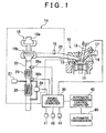
- FIGS. 1 to 6 are views showing one embodiment of a control apparatus for a diesel vehicle according to the invention.
- an engine 10 constructed as a multi-cylinder diesel engine has a plurality of cylinders 11 (only one of the cylinders is shown in FIG. 1 ).
- This engine 10 is equipped with a fuel injection valve 12 for injecting fuel into a combustion chamber 13 in each of the cylinders 11, an exhaust device 14 for discharging exhaust gas from the combustion chamber 13, a supercharger 15 for compressing air with the aid of the energy of exhaust gas in the exhaust device 14 and supercharging the combustion chamber 13 with the compressed air through an intake passage 16, and a glow plug 17 that glows through the supply of current at the time of cold start of the engine 10 or the like to provide assistance in starting the engine 10.
- the fuel injection valve 12 introduces fuel (e.g., light oil) pressurized to a high fuel pressure (pressure of fuel) by a supply pump (not shown), and injects the fuel into the combustion chamber 13 in accordance with an injection command signal from an engine control computer (an electronic control unit, hereinafter referred to as an engine ECC), which will be described later.
- This fuel injection valve 12 is constructed as an electromagnetically driven known needle valve.
- the ratio of a valve-open time of the fuel injection valve to the predetermined time (duty ratio) is controlled. Fuel can thereby be injected at a timing and an opening degree that correspond to the injection command signal.
- an intake system for sucking air into the combustion chamber 13 is equipped with an intake manifold, an air cleaner located upstream of the intake manifold to purify intake air by means of a filter, an intercooler located downstream of the supercharger 15 to cool intake air that has risen in temperature through supercharging, an airflow meter for detecting the amount of intake air (intake air amount), and a throttle valve for adjusting the amount of intake air flowing into the engine 10.
- the throttle valve is an electronically controlled valve whose throttle opening degree can be continuously adjusted by an actuator portion (not shown).
- the supercharger 15 has a known structure. That is, the supercharger 15 has an intake air compressor 15a and an exhaust turbine 15b that are integrally coupled to each other in a rotational direction, and the exhaust turbine 15b is rotated with the aid of the energy of exhaust gas to rotate the intake air compressor 15a.
- the supercharger 15 can suck air at a positive pressure into the engine 10.
- the exhaust device 14 is equipped with an exhaust manifold 21 fitted to an exhaust port side of the engine 10, an exhaust pipe 22 located downstream of the exhaust manifold 21, an oxidation catalyst 23 fitted to the exhaust pipe 22 at a location downstream of the supercharger 15, a fuel injection valve 19 for post injection that is disposed in the exhaust pipe at a location upstream of the supercharger 15, a DPF device 25 fitted to the exhaust pipe 22 at a location downstream of the oxidation catalyst 23, exhaust gas temperature sensors 26a and 26b disposed in front of and behind (on both end sides of) the oxidation catalyst 23 respectively, a DPF upstream-side exhaust pressure sensor 27 located between the oxidation catalyst 23 and the DPF device 25, and a differential pressure sensor 28 for detecting the differential pressure across the DPF device 25.
- the fuel injection valve 19 for post injection injects into the exhaust manifold 21 part of fuel that has been pumped up by the supply pump (not shown).
- the fuel injection valve 19 for post injection opens and injects the fuel into the exhaust manifold 21, thereby enabling gasification of the fuel.
- the combustion of particulate matter deposited in the DPF device 25 is promoted.
- the oxidation catalyst 23 suitably adjusts, for example, the concentrations of oxygen and unburned components (HC) in exhaust gas, thereby making it possible to reduce NOx in exhaust gas to NO 2 and NO and cause the NO 2 and NO to react with the HC and CO in exhaust gas so that the NO 2 and NO are turned into N 2 , and to oxidize the HC and CO to H 2 O and CO 2 .
- the fuel post-injected from the fuel injection valve 19 for post injection and gasified is also utilized to adjust the concentrations of oxygen and unburned components (HC) in exhaust gas.
- the DPF device 25 adopts, for example, a monolithically structured filter as a filter (not shown in detail) for trapping particulate matter in exhaust gas of the engine 10, with a view to achieving both a high trapping rate of particulate matter and a low pressure loss in the exhaust pipe.
- the DPF device 25 has a known structure with the filter whose pores have an optimized diameter and are distributed in an optimized manner. In combination with the oxidation catalyst 23, the DPF device 25 can further enhance the capacity to purify exhaust gas.
- an exhaust passage endowed with the function of a waste gate valve and designed to bypass the exhaust turbine 15b in accordance with the opening degree of the waste gate valve can be formed on the exhaust turbine 15b side of the supercharger 15.
- a passage for exhaust gas recirculation (hereinafter referred to as EGR), namely, an EGR passage that bypasses the combustion chamber in the engine 10 to establish communication between the exhaust passage in the exhaust manifold 21 and the intake passage in the intake manifold, an EGR valve for adjusting the amount of exhaust gas recirculated by the EGR passage, and an EGR cooler for cooling the exhaust gas recirculated through the EGR passage can be provided.
- the supply of current to the supply pump and the like, the amounts of fuel injected by the fuel injection valves 12 and 19, and the like are electronically controlled by the engine ECC 30.
- the engine ECC 30 is configured to execute a predetermined control program at intervals of a predetermined time.
- the engine ECC 30, whose detailed hardware configuration is not shown, is configured with a central processing unit (CPU), a ROM (read only memory), a RAM (random access memory), a backup memory such as an electronically erasable and programmable read only memory (EEPROM) or the like, an input interface circuit including an A/D converter, a buffer, and the like, and an output interface circuit including drive circuits and the like.
- CPU central processing unit
- ROM read only memory
- RAM random access memory
- EEPROM electronically erasable and programmable read only memory
- an accelerator opening degree sensor 41 for detecting the depression amount of an accelerator pedal (not shown)
- a vehicle speed sensor 42 vehicle speed detecting means for detecting the running speed or wheel rotational speed of the vehicle mounted with the engine 10
- a crank angle sensor 43 rotational speed sensor
- an airflow meter (not shown), a throttle opening degree sensor (not shown), an intake pipe internal pressure sensor (not shown) for detecting the intake pressure (supercharging pressure) of the engine 10, and the like are connected to the input interface circuit of the engine ECC 30. Pieces of information detected by a group of these sensors are acquired by the engine ECC 30.
- a required acceleration amount detected by the accelerator opening degree sensor 41 may be detected as an amount of change (increase) in the throttle opening degree detected by the throttle opening degree sensor.
- the airflow meter, the throttle opening degree sensor, the crank angle sensor, the vehicle speed sensor, the intake pipe internal pressure sensor, and the like constitute means for detecting the operation state of the engine 10.
- the supply pump, the fuel injection valves 12 and 19, and the like are connected to the output interface circuit of the engine ECC 30 via the drive circuits (not shown) respectively.
- ⁇ P is a differential pressure across the filter, that C1, ⁇ , and a are constants calculated through an experiment, that ⁇ is a viscosity coefficient calculated as a function f(T) of exhaust gas temperature, and that Q is a flow rate of exhaust gas) or a map (which shows a correlation in which the amount of deposited particulate matter increases as the differential pressure increases), and a regeneration treatment program for carrying out a regeneration treatment of the filter of the DPF device 25 by causing the fuel injection valve 19 for post injection to perform post injection for a time corresponding to the amount of deposited particulate matter when the particulate matter are deposited in the filter.
- the engine ECC 30 functions as regeneration treatment means for carrying out the regeneration treatment of the filter in cooperation with the fuel injection valve 19 for post injection.
- Stored in the ROM of the engine ECC 30 is a known output limiting program for selectively limiting the maximum output of the engine 10 when the amount of the particulate matter deposited in the filter of the DPF device 25 is equal to or larger than a predetermined amount, on the basis of pieces of information detected by the exhaust gas temperature sensors 26a and 26b, the DPF upstream-side exhaust pressure sensor 27, and the differential pressure sensor 28.
- the engine ECC 30 also functions as output limiting means for limiting the maximum output of the engine 10 when the amount of the particulate matter is equal to or more than a predetermined amount.
- the limiting of the maximum output mentioned herein means, for example, setting the maximum value of the accelerator opening degree smaller than usual and hence imposing a limit such that a usually obtained maximum throttle opening degree is not obtained for a maximum depression amount of the accelerator pedal.
- the engine ECC 30 In executing the output limiting program, the engine ECC 30 sends and outputs pieces of information on an output limiting width of the program (e.g., a limiting amount (%) from the maximum accelerator opening degree, an upper-limit engine rotational speed (rpm), a rate of decrease in injection amount, or the like), a value of a differential pressure across the DPF device (an instantaneous value for every calculation cycle) as information detected by the differential pressure sensor 28, an accelerator opening degree, a vehicle speed, and the like to an automatic transmission control computer (hereinafter referred to as an automatic transmission ECC) 40 as pieces of control information.
- the engine ECC 30 is equipped with a control program and a communication IC in order to send and output those pieces of control information.
- the automatic transmission ECC 40 regarded as means for performing automatic shift control of a known automatic transmission 60.
- the automatic transmission ECC 40 is configured with a CPU, a ROM, a RAM, a backup memory, an input interface circuit, and an output interface circuit.
- a shift diagram in which a shift stage of the automatic transmission 60 corresponding to the accelerator opening degree and the vehicle speed as the pieces of control information from the engine ECC 30 is prescribed is stored in the ROM of this automatic transmission ECC 40.
- the shift diagram M stored in the ROM of the automatic transmission ECC 40 is designed as a diagram showing all running states with axes of ordinate and abscissa representing accelerator opening degree and vehicle speed respectively.
- a plurality of upshift lines Lu1, Lu2, Lu3, and Lu4 representing timings for making an upshift (indicated by solid lines in FIG. 2 ) and a plurality of downshift lines Ld1, Ld2, Ld3, and Ld4 representing timings for making a downshift are each set in accordance with a maximum output in a preset normal output range of the engine 10.
- the automatic transmission ECC 40 has the function of shift condition changeover means for changing the upshift lines Lu1, Lu2, Lu3, and Lu4 in the shift diagram M to changed upshift lines Lc1, Lc2, Lc3, and Lc4 shown in FIG. 2 in high accelerator opening degree ranges respectively in cooperation with the engine ECC 30, when the accelerator opening degree exceeds a predetermined opening degree and the maximum output of the engine 10 is limited, so as to reduce an upshift threshold speed in comparison with other cases (normal cases where the output is not limited).
- Control programs for changing those upshift lines are stored in the ROMs of the engine ECC 30 and the automatic transmission ECC 40.
- an upshift to the second speed range is made at about 37 km/h after running in the first speed range with a maximum output corresponding to an accelerator opening degree of 100 [%]. If the maximum output is limited such that the engine rotational speed does not become higher than about 4000 rpm although the engine rotational speed is supposed to reach 5200 rpm in the case of normal control while running in the first speed range with the maximum output, the engine ECC 30 sends information indicating the degree of the limiting of the output (limiting width) to the automatic transmission ECC 40.
- the automatic transmission ECC 40 as the shift condition changeover means determines change amounts of the upshift lines Lu1, Lu2, Lu3, and Lu4 toward the low vehicle speed side (amounts of changes in vehicle speed to the changed upshift lines Lc1, Lc2, Lc3, and Lc4) in accordance with the amount of the maximum output of the engine 10 limited by the engine ECC 30 as the output limiting means.
- the automatic transmission ECC 40 as the shift condition changeover means changes the corresponding downshift lines Ld1, Ld2, Ld3, and Ld4 in the shift diagram M in accordance with the change amounts of the upshift lines Lu1, Lu2, Lu3, and Lu4 toward the low vehicle speed side respectively so as to reduce un downshift threshold speed in comparison with the aforementioned other cases, when the accelerator opening degree exceeds the predetermined opening degree and the maximum output of the engine 10 is limited.
- Changed downshift lines in this case are not shown individually. For example, however, a changed downshift line Ldlm that has been changed from the downshift line Ld1 is set so as to make a shift on the low vehicle speed side in comparison with the corresponding one Lc 1 of the changed upshift lines.
- the engine ECC 30 also functions as malfunction detecting means for detecting, from an output state of each of the differential pressure sensor 28 and the DPF upstream-side exhaust pressure sensor 27 (a certain sensor output is not obtained or an abnormal value outside a normal sensor output range (so-called deviation from range) is indicated), that the differential pressure sensor 28 or the DPF upstream-side exhaust pressure sensor 27 has a malfunction or is in a sensor output state similar to the malfunction.
- a malfunction detecting program for carrying out such detection is stored in the ROM of the engine ECC 30.
- the control of running drive output is performed by the engine ECC 30 and the automatic transmission ECC 40.
- the engine ECC 30 determines, on the basis of information detected by the differential pressure sensor 28, whether a differential pressure across the DPF device is abnormal or normal (step S11), depending on whether or not the value of the differential pressure across the DPF device is higher than a predetermined threshold ⁇ p1 for making a determination on an abnormality in differential pressure.
- a predetermined threshold ⁇ p1 for making a determination on an abnormality in differential pressure.
- a malfunction indicator lamp MIL
- a maximum output of the engine 10 that allows continuous operation without causing an increase in the number of malfunctioning parts at an excessively high differential pressure across the DPF device is calculated for that differential pressure across the DPF device on the basis of, for example, a maximum output limiting map (see FIG. 4A ) obtained through an experiment conducted in advance or an operation state of the engine 10 (engine rotational speed or the like) (step S13).
- the calculated maximum output is thereafter used as an output limiting threshold.
- the output of the differential pressure sensor 28 may exceed the abnormality determining threshold ⁇ p1 for a short time even in a normal operation state. Therefore, even when it is determined that there is an abnormality, the output of the differential pressure sensor 28 may return to a normal differential pressure range in a short time.
- the output of the engine 10 itself fluctuates. Therefore, when the engine reaches an output within a limiting range (engine rotational speed and torque), only that portion of the output of the engine which exceeds the limiting range is limited (see FIG. 4B ).
- step S 14 It is then determined whether or not the output limiting threshold is larger than a certain threshold Hm (step S 14).
- the output limiting threshold is equal to or smaller than the aforementioned certain threshold Hm (NO in step S 14)
- the vehicle is prohibited from running with a view to preventing the DPF device 25 or oil seals for the parts of the exhaust system from being damaged, preventing the supercharger from being damaged due to a rise in temperature, and the like.
- a processing of forcibly returning the gear of the automatic transmission to a neutral position is performed (step S 15).
- the output limiting threshold is larger than the aforementioned certain threshold Hm (YES in step S14)
- the maximum output of the engine 10 is controlled using the output limiting threshold as an upper limit (step S16).
- the output limiting threshold may be a value fluctuating in accordance with a differential pressure.
- a shift schedule is changed (step S17) to change the upshift lines Lu1, Lu2, Lu3, and Lu4 in the shift diagram M to the changed upshift lines Lc1, Lc2, Lc3, and Lc4 respectively in the high accelerator opening degree range so as to reduce an upshift threshold speed in comparison with normal cases where the output is not limited, in an operation range where the accelerator opening degree exceeds the predetermined opening degree (and the maximum output of the engine 10 is limited).
- the upshift lines are each set so as to make an upshift along a limited maximum torque curve (within a range where the torque decreases as the rotational speed of the engine increases) within a range exceeding a road load line corresponding to an accelerator opening degree at the time when the vehicle runs on a flat road surface without being accelerated or decelerated.
- the downshift lines Ld1, Ld2, Ld3, and Ld4 are changed in accordance with the change amounts of the upshift lines Lu1, Lu2, Lu3, and Lu4 toward the low vehicle speed side respectively so as to make a downshift on a low vehicle speed side in comparison with other cases.
- an upshift to the second speed range is made at about 37 km/h after running in the first speed range with the maximum output corresponding to the accelerator opening degree of 100 [%]. If the maximum output is limited such that the engine rotational speed does not become as high as only about 4000 rpm although the engine rotational speed is supposed to reach 5200 rpm in the case of normal control while running in the first speed range with the maximum output, the engine ECC 30 sends information indicating the degree of the limiting of the output (limiting width) to the automatic transmission ECC 40.
- the automatic transmission ECC 40 as the shift condition changeover means determines change amounts of the upshift lines Lu1, Lu2, Lu3, and Lu4 toward the low vehicle speed side (amounts of changes in vehicle speed to the changed upshift lines Lc1, Lc2, Lc3, and Lc4) in accordance with the amount of the maximum output of the engine 10 limited by the engine ECC 30 as the output limiting means.
- step S18 it is determined whether the differential pressure across the DPF device is abnormal or normal (step S18), depending on whether or not the value of the differential pressure across the DPF device is equal to or smaller than the predetermined determination threshold ⁇ p2 for determining whether or not the differential pressure is normal.
- a return to normal operation is made.
- the processings stating from the step of calculating the maximum output are performed again.
- the engine ECC 30 first determines on the basis of information detected by the differential pressure sensor 28 whether or not the differential pressure sensor 28 has a malfunction (is in an output state within a malfunction range) (step S21).
- the differential pressure sensor 28 is normal (NO in step S21)
- a return to normal control is made.
- the MIL lamp is subsequently lit (step S22), and an amount of soot deposited in the DPF device 25 is estimated according to a known estimation method on the basis of pieces of detected information such as a running distance, a fuel injection amount, an engine rotational speed, and the like (step S23).
- step S24 It is then determined whether or not the estimated amount of the deposited soot is larger than a predetermined amount (step S24).
- soot burning control is performed by carrying out post injection corresponding to the estimated amount of the deposited soot (step S25).
- a maximum output (shaft output) of the engine 10 that allows continuous operation without causing an increase in the number of malfunctioning parts is calculated for the amount of the deposited soot in the same manner as a known method, namely, on the basis of, for example, a map of torque decrease rate and PM deposition amount (see FIG. 6A ) or a map of decrease coefficient and engine rotational speed (see FIG 6B ), by multiplying a torque decrease rate by a decrease coefficient so as to limit a maximum torque on a high rotation range side (step S26).
- the map of torque decrease rate and PM deposition amount or the map of decrease coefficient and engine rotational speed is, for example, stored in the ROM.
- the maximum output thus calculated is used as an output limiting threshold.
- the limiting of the maximum output in this case serves to, for example, make a transition from an output characteristic A in a maximum output range indicated by a solid line in FIG. 6C to an output characteristic B indicated by broken lines in FIG. 6C .
- a maximum torque Ta indicated by the solid line is limited to a maximum torque Tb indicated by the broken lines.
- the throttle opening degree and the fuel injection amount are limited, the calculated limiting of the output is carried out, and soot burning control within a predetermined range is performed (step S27).
- the shift schedule is changed (step S28) to change the upshift lines Lu1, Lu2, Lu3, and Lu4 in the shift diagram M to the changed upshift lines Lc1, Lc2, Lc3, and Lc4 respectively in the high accelerator opening degree range so as to make an upshift on a low vehicle speed side in comparison with normal cases where the output is not limited, in the operation range where the accelerator opening degree is larger than the predetermined opening degree (and the maximum output of the engine 10 is limited).
- the upshift lines are each set so as to make an upshift along a curve of the limited maximum torque Tb within a range exceeding a road load line corresponding to an accelerator opening degree at the time when the vehicle runs on a flat road surface without being accelerated or decelerated.
- step S29 It is then determined again whether or not the differential pressure sensor 28 has a malfunction (is in an output state within a malfunction range) (step S29). When a normal sensor output state has been restored (NO in step S29), a return to normal control is made. However, when it is determined that the differential pressure sensor 28 has a malfunction, the MIL lamp is lit again (step S22), and the processings starting from the step of estimating the amount of the soot deposited in the DPF device 25 are performed (steps S23 to S29).
- the maximum output of the engine 10 is limited by the engine ECC 30 as the output limiting means when the particulate matter is deposited in the predetermined amount or more in the filter of the DPF device 25 despite the regeneration treatment for the filter.
- the upshift lines Lu1 to Lu4 in the shift diagram M are changed to the changed upshift lines Lc1 to Lc4 respectively so as to make an upshift on a low vehicle speed side in comparison with the case where the maximum output of the engine is not limited, when the accelerator opening degree is larger than the predetermined opening degree and the maximum output of the engine 10 is limited.
- the change amounts of the upshift lines Lu1 to Lu4 toward the low vehicle speed side are decided in accordance with the limiting amount of the engine maximum output. Therefore, an upshift is made at an appropriate timing corresponding to the limiting amount of the maximum output of the engine 10.
- the corresponding downshift lines Ld1 to Ld4 in the shift diagram are changed in accordance with the change amounts of the upshift lines Lu1 to Lu4 toward the low vehicle speed side respectively so as to make a downshift on the low vehicle speed side in comparison with other cases, when the accelerator opening degree is larger than the predetermined opening degree and the maximum output of the engine 10 is limited. Therefore, in accordance with the change amounts of the upshift lines Lu 1 to Lu4 in the high accelerator opening degree to the changed upshift lines Lc1 to Lc4 on the low vehicle speed side, the downshift lines Ld1 to Ld4 are correspondingly changed toward the low vehicle speed side (e.g., Ld1m). As a result, stable running performance with restricted occurrence of hunting is ensured in the automatic transmission 60.
- the low vehicle speed side e.g., Ld1m
- the automatic transmission ECC 40 constitutes the shift condition changeover means.
- the upshift lines Lu1 to Lu4 in the shift diagram M are changed to the changed upshift lines Lc1 to Lc4 respectively so as to reduce an upshift threshold speed in comparison to when the maximum output of the engine is not limited, when the accelerator opening degreeexceeds the predetermined opening degree and the maximum output of the engine 10 is limited.
- the shift condition changeover means more preferably makes a changeover in condition will be described.
- a program for fulfilling the function as running load detecting means for detecting a current running load of the vehicle on the basis of an accelerator opening degree and a vehicle speed is stored in the ROM of the automatic transmission ECC 40.
- the automatic transmission ECC 40 prohibits, on the basis of information detected by the running load detecting means, the shift condition changeover means from functioning to change the upshift lines Lu1, Lu2, Lu3, and Lu4 toward the low vehicle speed side (to the changed upshift lines Lc1 to Lc4) respectively when the accelerator opening degree exceeds a predetermined opening degree and the maximum output of the engine 10 is limited with the running load of the vehicle larger than a predetermined value L.
- FIGS. 7 and 8 show (Control in Differential Pressure Sensor Normal Mode) and (Control in Differential Pressure Sensor Malfunction Mode) in the foregoing embodiment of the invention respectively. The details of both the types of control have been described above and hence will not be described below.
- the upshift lines Lu1 to Lu4 are prohibited from being changed toward the low vehicle speed side when the running load is large as described above. Therefore, such an upshift in the automatic transmission 60 that causes a decrease in vehicle speed, which is ascribable to an insufficient torque at the time of a large running load, is prevented from being made. In consequence, stable running performance is ensured.
- the automatic transmission 60 is not limited to a combination of a torque converter and a multiple-stage transmission having a planetary gear, but can also be applied to a so-called multi-mode manual transmission (automatic control-type manual transmission) for making an automatic shift by controlling a clutch and an actuator for a gearbox while electronically controlling a throttle opening degree, or to a continuously variable transmission.
- a so-called multi-mode manual transmission automated control-type manual transmission
- the invention ensures that even in the case where the engine rotational speed does not rise as high as during normal operation due to the limiting of the maximum output of the engine and a sufficient rise in vehicle speed is not achieved although the accelerator opening degree is large, an upshift to a subsequent gear stage is made upon a rise in vehicle speed or a rise in accelerator opening degree across the upshift line that has been changed so as to make an upshift earlier on the low vehicle speed side in comparison with normal cases.
- the invention achieves an effect of making it possible to provide a control apparatus for a diesel vehicle that can reliably prevent the creation of an operation range where an upshift cannot be made and thus ensure sufficient running performance while preventing the malfunctions of parts by limiting the maximum output of the engine when a filter traps an excessive amount of particulate matter.
- the invention is useful to all types of control apparatuses for diesel vehicles that are designed to perform regeneration control of a DPF device and limit the output of an engine when soot is deposited in the DPF device.
- a control apparatus for a diesel vehicle is equipped with an engine ECC (30) as filter regeneration treatment means and output limiting means for limiting a maximum output of an engine, an accelerator opening degree sensor (41) for detecting an accelerator opening degree, a vehicle speed sensor (42) for detecting a vehicle speed, shift diagram storing means (40) for storing a shift diagram, shift setting means (40) for setting a shift stage of a transmission corresponding to the accelerator opening degree and the vehicle speed according to the shift diagram, and a transmission ECC (40) as shift condition changeover means for changing upshift lines Lu1, Lu2, Lu3, and Lu4 in the shift diagram M so as to reduce an upshift threshold speed in comparison to when the maximum output of the engine is not limited, when the accelerator opening degree exceeds a predetermined opening degree and the maximum output of the engine is limited.
- an engine ECC (30) as filter regeneration treatment means and output limiting means for limiting a maximum output of an engine
- an accelerator opening degree sensor (41) for detecting an accelerator opening degree
- a vehicle speed sensor (42) for detecting
Landscapes
- Engineering & Computer Science (AREA)
- Chemical & Material Sciences (AREA)
- Combustion & Propulsion (AREA)
- Mechanical Engineering (AREA)
- General Engineering & Computer Science (AREA)
- Processes For Solid Components From Exhaust (AREA)
- Control Of Vehicle Engines Or Engines For Specific Uses (AREA)
- Control Of Transmission Device (AREA)
Abstract
A control apparatus for a diesel vehicle is equipped with an engine ECC (30) as filter regeneration treatment means and output limiting means for limiting a maximum output of an engine, an accelerator opening degree sensor (41) for detecting an accelerator opening degree, a vehicle speed sensor (42) for detecting a vehicle speed, shift diagram storing means (40) for storing a shift diagram, shift setting means (40) for setting a shift stage of a transmission corresponding to the accelerator opening degree and the vehicle speed according to the shift diagram, and a transmission ECC (40) as shift condition changeover means for changing upshift lines Lu1, Lu2, Lu3, and Lu4 in the shift diagram M so as to reduce an upshift threshold speed in comparison to when the maximum output of the engine is not limited, when the accelerator opening degree exceeds a predetermined opening degree and the maximum output of the engine is limited.
Description
- The invention relates to a control apparatus and a control method for a diesel vehicle mounted with a diesel particulate filter (DPF) device and designed such that regeneration control of the DPF device is performed and the output of an engine is limited when soot is deposited in the DPF device.
- Recently, among automobiles mounted with diesel engines (hereinafter referred to as diesel vehicles), there has been known a diesel vehicle equipped with a DPF device for trapping particulate matter (hereinafter referred to also as PM) such as carbon particulates or the like in exhaust gas.
- In this type of conventional diesel vehicle, although the DPF device exhibits a high purification rate of particulate matter, a rise in exhaust pressure (back pressure of the engine) is caused when the particulate matter are deposited to form soot in the DPF device and the flow resistance of exhaust gas in an exhaust pipe increases. Therefore, the control of carrying out forced regeneration for burning the soot deposited in the DPF device through so-called post injection and the control of limiting the output of the engine are performed (e.g., see Japanese Patent Application Publication No.
2005-113752 JP-A-2005-113752 - There are also known a control apparatus for a diesel vehicle that is structured to detect a differential pressure across a DPF device by means of a sensor and estimate an amount of deposited particulate matter on the basis of information on the differential pressure to manage the time for a regeneration treatment and hence carry out effective post injection (e.g., see Japanese Patent Application Publication No.
2005-291036 JP-A-2005-291036 2006-9598 JP-A-2006-9598 5-332126 JP-A-5-332126 7-317529 JP-A-7-317529 - However, in each of the aforementioned control apparatuses for the diesel vehicles, when it becomes impossible to carry out the regeneration treatment with stability due to some abnormality occurring in the DPF device, an oxidation catalyst located upstream thereof, a fuel injection system for carrying out post injection, or the like, particulate matter is trapped in an excessive amount by a filter of the DPF device, and soot is deposited in the DPF device. Especially due to a rise in exhaust pressure at the time of high output, there is a problem in that the DPF device, sealing materials for an exhaust system, a supercharger, and the like become prone to breakage and the number of malfunctioning parts increases.
- In the case where the maximum output of the diesel engine is limited with a view to suppressing the rise in exhaust pressure, the rotational speed of the engine does not rise as high as during normal operation when the opening degree of an accelerator is large, due to the limiting of the maximum output. Therefore, a sufficient rise in vehicle speed is not achieved, and there arises an operation range where an upshift to a subsequent gear stage to be selected cannot be made in an automatic transmission whose shift condition is so set as to make an upshift in the vicinity of a maximum output during normal operation of the engine. In consequence, there is caused a problem in that sufficient running performance cannot be ensured.
- The invention therefore provides a control apparatus and a control method for a diesel vehicle that make it possible to reliably prevent the creation of an operation range where an upshift cannot be made and ensure sufficient running performance while preventing a malfunction by limiting a maximum output of an engine when a filter traps an excessive amount of particulate matter.
- In a first aspect for implementing the invention, (1) a control apparatus for a diesel vehicle mounted with an engine and a transmission is equipped with regeneration treatment means for carrying out a regeneration treatment of a filter for trapping particulate matter in exhaust gas of the engine when the particulate matter is deposited in the filter, output limiting means for limiting a maximum output of the engine when an amount of the particulate matter deposited in the filter is equal to or larger than a predetermined amount, accelerator opening degree detecting means for detecting an accelerator opening degree of the vehicle, vehicle speed detecting means for detecting a vehicle speed of the vehicle, shift diagram storing means for storing a shift diagram in which shift stages of the transmission corresponding to the accelerator opening degree and the vehicle speed are prescribed, shift setting means for setting a shift stage of the transmission corresponding to the accelerator opening degree and the vehicle speed according to the shift diagram, and shift condition changeover means for changing an upshift line in the shift diagram so as to reduce an upshift threshold speed in comparison to when the maximum output of the engine is not limited, when the accelerator opening degree exceeds a predetermined opening degree and the maximum output of the engine is limited.
- Owing to this configuration, the output limiting means limits the maximum output of the engine when the amount of the particulate matter is equal to or larger than the predetermined amount. The upshift line in the shift diagram is changed to reduce the upshift threshold speed in comparison to when the maximum output of the engine is not limited, when the accelerator opening degree exceeds the predetermined opening degree and the maximum output of the engine is limited. Accordingly, even in the case where the engine rotational speed does not rise as high as during normal operation due to the limiting of the maximum output of the engine and a sufficient rise in vehicle speed is not achieved although the accelerator opening degree is large, an upshift to a subsequent gear stage is made upon a rise in vehicle speed or a rise in accelerator opening degree across the upshift line that has been changed to reduce an upshift threshold speed in comparison with normal cases. As a result, sufficient running performance is ensured, and fuel consumption is improved as well.
- In the control apparatus for the diesel vehicle according to the foregoing first aspect for implementing the invention, (2) the shift condition changeover means may determine a change amount of the upshift line toward a low vehicle speed side in accordance with an amount of the maximum output of the engine limited by the output limiting means.
- In this case, an upshift is made at an appropriate timing in accordance with the limited amount of the maximum output of the engine.
- The control apparatus for the diesel vehicle according to the foregoing first aspect for implementing the invention may be equipped with (3) running load detecting means for detecting a running load of the vehicle, and changeover prohibiting means for prohibiting the upshift line from being changed toward the low vehicle speed side by the shift condition changeover means, on the basis of the running load of the vehicle, when the accelerator opening degree exceeds the predetermined opening degree and the running load of the vehicle is larger than a predetermined value, and when the maximum output of the engine is limited.
- In this case, such an upshift that causes a decrease in vehicle speed, which is ascribable to an insufficient torque at the time of a large running load, is avoided. As a result, stable running performance is ensured.
- In the control apparatus for the diesel vehicle according to the foregoing first aspect for implementing the invention, (4) when the accelerator opening degree exceeds the predetermined opening degree and the maximum output of the engine is limited, the shift condition changeover means may change an upshift line between one shift stage and another shift stage in the shift diagram, and may change a downshift line between the one shift stage and the another shift stage in the shift diagram, in accordance with the change amount of the upshift line.
- In this case, in accordance with the change amount of the upshift line toward the low vehicle speed side in a large accelerator opening degree range, the downshift line is correspondingly changed toward the low vehicle speed side. As a result, stable running performance with restricted occurrence of hunting is ensured.
- In the control apparatus for the diesel vehicle according to the foregoing first aspect for implementing the invention, (5) the transmission may be an automatic transmission capable of making an automatic shift to a shift stage set by the shift setting means.
- Owing to this configuration, the creation of an operation range where an upshift cannot be made in the automatic transmission can be reliably prevented to ensure sufficient running performance.
- In the control apparatus for the diesel engine according to the foregoing first aspect for implementing the invention, (6) the transmission may be a manual transmission, and the shift setting means may be constructed as a shift indicator for indicating a timing for making an upshift.
- In this case, the creation of an operation range where an upshift cannot be made with a normal operation feeling is prevented while preventing the malfunctions of parts by limiting the maximum output of the engine when the filter traps an excessive amount of the particulate matter. As a result, sufficient running performance and a satisfactory shift operation feeling can be ensured.
- A second aspect for implementing the invention concerns a control method for a diesel vehicle mounted with an engine and a transmission. In this control method, a maximum output of the engine is limited when an amount of particular matter deposited in a filter for trapping particulate matter in exhaust gas of the engine is equal to or larger than the predetermined amount. An upshift threshold speed is reduced in comparison to when the maximum output of the engine is not limited, when the maximum output of the engine is limited and an accelerator opening degree is larger than a predetermined opening degree.
- In the control method for the diesel vehicle mounted with the engine and the transmission according to the foregoing aspect for implementing the invention, it may be appropriate to determine that the amount of the particulate matter deposited in the filter is equal to or more than the predetermined mount, when a differential pressure across the filter is higher than a first prescribed value. An output limit threshold of the engine at the differential pressure is then calculated. The maximum output of the engine is limited using the output limit threshold as an upper limit when the output limit threshold is larger than a predetermined threshold. An upshift threshold speed may be reduced in comparison to when the maximum output of the engine is not limited, when the maximum output of the engine is limited and the accelerator opening degree is larger than the predetermined opening degree.
- In the control method for the diesel vehicle according to the foregoing aspect for implementing the invention, it may be prohibited to reduce the upshift threshold speed when the maximum output of the engine is limited, the accelerator opening degree is larger than the predetermined opening degree, and a load of the engine is larger than a predetermined value.
- In the control method for the diesel vehicle according to the foregoing second aspect for implementing the invention, the amount of the particulate matter deposited in the filter may be estimated on the basis of a running distance, a fuel injection amount, and an engine rotational speed when the sensor for detecting the differential pressure across the filter has a malfunction. The regeneration treatment of the filter for burning the particulate matter is carried out when the amount of the particulate matter is equal to or smaller than the predetermined amount. The output limit threshold of the engine based on an amount of the deposited particulate matter is calculated when the amount of the particulate matter is larger than the predetermined amount, and the maximum output of the engine is limited using the output limit threshold as an upper limit. An upshift threshold speed is reduced in comparison to when the maximum output of the engine is not limited, when the maximum output of the engine is limited and the accelerator opening degree is larger than the predetermined opening degree.
- In the control method for the diesel vehicle according to the foregoing aspect for implementing the invention, it may be prohibited to reduce the upshift threshold speed when the maximum output of the engine is limited, the accelerator opening degree is larger than the predetermined opening degree, and a running load of the vehicle is larger than a predetermined value.
- According to the foregoing aspects for implementing the invention, even when the engine rotational speed does not rise as high as during normal operation due to the limiting of the maximum output of the engine and a sufficient rise in vehicle speed is not achieved although the accelerator opening degree is large, an upshift to a subsequent gear stage is made upon a rise in vehicle speed or a rise in accelerator opening degree across an upshift line that has been changed to reduce the upshift threshold speed in comparison with normal cases. Therefore, the control method and the control apparatus for the diesel vehicle that make it possible to prevent the creation of an operation range where an upshift cannot be made and ensure sufficient running performance while preventing the malfunctions of parts by limiting the maximum output of the engine when the filter traps an excessive amount of the particulate matter can be provided.
- The foregoing and further objects, features and advantages of the invention will become apparent from the following description of preferred embodiments with reference to the accompanying drawings, wherein like numerals are used to represent like elements and wherein:
-
FIG. 1 is a schematic configurational view showing one embodiment of a control apparatus for a diesel vehicle according to the invention; -
FIG. 2 is a shift diagram memorized and stored in the control apparatus for the diesel vehicle according to one embodiment of the invention; -
FIG. 3 is a flowchart showing the overall flow of a control program that is executed by the control apparatus for the diesel vehicle according to one embodiment of the invention when a differential pressure sensor is in a normal mode; -
FIGS. 4A and 4B are illustrative views schematically showing the contents of limitation imposed on a maximum output of an engine by the control apparatus for the diesel vehicle according to one embodiment of the invention; -
FIG. 5 is a flowchart showing the overall flow of a control program that is executed by the control apparatus for the diesel vehicle according to one embodiment of the invention when the differential pressure sensor is in a malfunction mode; -
FIG. 6A is an illustrative view of a map of torque decrease rate and PM deposition amount that is stored in the control apparatus for the diesel vehicle according to one embodiment of the invention; -
FIG. 6B is an illustrative view of a map of decrease coefficient and engine rotational speed that is stored in the control apparatus for the diesel vehicle according to one embodiment of the invention; -
FIG. 6C is a graph showing, as torque characteristics, the contents of limitation imposed on a maximum output of the engine by the control apparatus for the diesel vehicle according to one embodiment of the invention, with an axis of ordinate representing output and torque and an axis of abscissa representing engine rotational speed; -
FIG. 7 is a flowchart showing the overall flow of a control program that is executed by a control apparatus for a diesel vehicle according to an additional embodiment of the invention when a differential pressure sensor is in a normal mode; and -
FIG. 8 is a flowchart showing the overall flow of a control program that is executed by the control apparatus for the diesel vehicle according to the additional embodiment of the invention when the differential pressure sensor is in a malfunction mode. - The preferred embodiments of the invention will be described hereinafter on the basis of the drawings.
-
FIGS. 1 to 6 are views showing one embodiment of a control apparatus for a diesel vehicle according to the invention. - First of all, the configuration of the control apparatus will be described. Referring to
FIG. 1 , anengine 10 constructed as a multi-cylinder diesel engine has a plurality of cylinders 11 (only one of the cylinders is shown inFIG. 1 ). Thisengine 10 is equipped with afuel injection valve 12 for injecting fuel into acombustion chamber 13 in each of thecylinders 11, anexhaust device 14 for discharging exhaust gas from thecombustion chamber 13, asupercharger 15 for compressing air with the aid of the energy of exhaust gas in theexhaust device 14 and supercharging thecombustion chamber 13 with the compressed air through anintake passage 16, and aglow plug 17 that glows through the supply of current at the time of cold start of theengine 10 or the like to provide assistance in starting theengine 10. - The
fuel injection valve 12 introduces fuel (e.g., light oil) pressurized to a high fuel pressure (pressure of fuel) by a supply pump (not shown), and injects the fuel into thecombustion chamber 13 in accordance with an injection command signal from an engine control computer (an electronic control unit, hereinafter referred to as an engine ECC), which will be described later. Thisfuel injection valve 12 is constructed as an electromagnetically driven known needle valve. In accordance with a pulse-like injection command signal at intervals of a predetermined time, the ratio of a valve-open time of the fuel injection valve to the predetermined time (duty ratio) is controlled. Fuel can thereby be injected at a timing and an opening degree that correspond to the injection command signal. - Although not shown in detail, an intake system for sucking air into the
combustion chamber 13 is equipped with an intake manifold, an air cleaner located upstream of the intake manifold to purify intake air by means of a filter, an intercooler located downstream of thesupercharger 15 to cool intake air that has risen in temperature through supercharging, an airflow meter for detecting the amount of intake air (intake air amount), and a throttle valve for adjusting the amount of intake air flowing into theengine 10. The constructions of these components are identical or similar to those of known ones. For example, the throttle valve is an electronically controlled valve whose throttle opening degree can be continuously adjusted by an actuator portion (not shown). - The
supercharger 15 has a known structure. That is, thesupercharger 15 has anintake air compressor 15a and anexhaust turbine 15b that are integrally coupled to each other in a rotational direction, and theexhaust turbine 15b is rotated with the aid of the energy of exhaust gas to rotate theintake air compressor 15a. Thesupercharger 15 can suck air at a positive pressure into theengine 10. - On the other hand, the
exhaust device 14 is equipped with anexhaust manifold 21 fitted to an exhaust port side of theengine 10, anexhaust pipe 22 located downstream of theexhaust manifold 21, anoxidation catalyst 23 fitted to theexhaust pipe 22 at a location downstream of thesupercharger 15, afuel injection valve 19 for post injection that is disposed in the exhaust pipe at a location upstream of thesupercharger 15, aDPF device 25 fitted to theexhaust pipe 22 at a location downstream of theoxidation catalyst 23, exhaustgas temperature sensors oxidation catalyst 23 respectively, a DPF upstream-sideexhaust pressure sensor 27 located between theoxidation catalyst 23 and theDPF device 25, and adifferential pressure sensor 28 for detecting the differential pressure across theDPF device 25. - In addition to the
fuel injection valve 12, thefuel injection valve 19 for post injection injects into theexhaust manifold 21 part of fuel that has been pumped up by the supply pump (not shown). When fuel is supplied to thefuel injection valve 19 for post injection at a fuel pressure equal to or higher than a predetermined pressure, thefuel injection valve 19 for post injection opens and injects the fuel into theexhaust manifold 21, thereby enabling gasification of the fuel. Thus, the combustion of particulate matter deposited in theDPF device 25 is promoted. - The
oxidation catalyst 23 suitably adjusts, for example, the concentrations of oxygen and unburned components (HC) in exhaust gas, thereby making it possible to reduce NOx in exhaust gas to NO2 and NO and cause the NO2 and NO to react with the HC and CO in exhaust gas so that the NO2 and NO are turned into N2, and to oxidize the HC and CO to H2O and CO2. The fuel post-injected from thefuel injection valve 19 for post injection and gasified is also utilized to adjust the concentrations of oxygen and unburned components (HC) in exhaust gas. - The
DPF device 25 adopts, for example, a monolithically structured filter as a filter (not shown in detail) for trapping particulate matter in exhaust gas of theengine 10, with a view to achieving both a high trapping rate of particulate matter and a low pressure loss in the exhaust pipe. TheDPF device 25 has a known structure with the filter whose pores have an optimized diameter and are distributed in an optimized manner. In combination with theoxidation catalyst 23, theDPF device 25 can further enhance the capacity to purify exhaust gas. - Although not shown, an exhaust passage endowed with the function of a waste gate valve and designed to bypass the
exhaust turbine 15b in accordance with the opening degree of the waste gate valve can be formed on theexhaust turbine 15b side of thesupercharger 15. Further, a passage for exhaust gas recirculation (hereinafter referred to as EGR), namely, an EGR passage that bypasses the combustion chamber in theengine 10 to establish communication between the exhaust passage in theexhaust manifold 21 and the intake passage in the intake manifold, an EGR valve for adjusting the amount of exhaust gas recirculated by the EGR passage, and an EGR cooler for cooling the exhaust gas recirculated through the EGR passage can be provided. - On the other hand, the supply of current to the supply pump and the like, the amounts of fuel injected by the
fuel injection valves engine ECC 30. Theengine ECC 30 is configured to execute a predetermined control program at intervals of a predetermined time. - The
engine ECC 30, whose detailed hardware configuration is not shown, is configured with a central processing unit (CPU), a ROM (read only memory), a RAM (random access memory), a backup memory such as an electronically erasable and programmable read only memory (EEPROM) or the like, an input interface circuit including an A/D converter, a buffer, and the like, and an output interface circuit including drive circuits and the like. - In addition to the exhaust
gas temperature sensors exhaust pressure sensor 27, and thedifferential pressure sensor 28, an accelerator opening degree sensor 41 (accelerator opening degree detecting means) for detecting the depression amount of an accelerator pedal (not shown), a vehicle speed sensor 42 (vehicle speed detecting means) for detecting the running speed or wheel rotational speed of the vehicle mounted with theengine 10, and a crank angle sensor 43 (rotational speed sensor) for outputting a signal corresponding to an engine rotational speed every time a crankshaft rotates by a predetermined angle are connected to the input interface circuit of theengine ECC 30. Furthermore, an airflow meter (not shown), a throttle opening degree sensor (not shown), an intake pipe internal pressure sensor (not shown) for detecting the intake pressure (supercharging pressure) of theengine 10, and the like are connected to the input interface circuit of theengine ECC 30. Pieces of information detected by a group of these sensors are acquired by theengine ECC 30. - A required acceleration amount detected by the accelerator
opening degree sensor 41 may be detected as an amount of change (increase) in the throttle opening degree detected by the throttle opening degree sensor. The airflow meter, the throttle opening degree sensor, the crank angle sensor, the vehicle speed sensor, the intake pipe internal pressure sensor, and the like constitute means for detecting the operation state of theengine 10. - The supply pump, the
fuel injection valves engine ECC 30 via the drive circuits (not shown) respectively. - Stored in the ROM of the
engine ECC 30 are, for example, a calculation formula for calculating the amount of particulate matter deposited in the filter of theDPF device 25 on the basis of the differential pressure level detected by the differential pressure sensor 28 (e.g., PMf = (1/C1)(ΔP/(µ·Qα))-a, which is mentioned in paragraph 0073 of Japanese Patent Application Publication No.2005-113752 JP-A-2005-113752 DPF device 25 by causing thefuel injection valve 19 for post injection to perform post injection for a time corresponding to the amount of deposited particulate matter when the particulate matter are deposited in the filter. Theengine ECC 30 functions as regeneration treatment means for carrying out the regeneration treatment of the filter in cooperation with thefuel injection valve 19 for post injection. - Stored in the ROM of the
engine ECC 30 is a known output limiting program for selectively limiting the maximum output of theengine 10 when the amount of the particulate matter deposited in the filter of theDPF device 25 is equal to or larger than a predetermined amount, on the basis of pieces of information detected by the exhaustgas temperature sensors exhaust pressure sensor 27, and thedifferential pressure sensor 28. Theengine ECC 30 also functions as output limiting means for limiting the maximum output of theengine 10 when the amount of the particulate matter is equal to or more than a predetermined amount. The limiting of the maximum output mentioned herein means, for example, setting the maximum value of the accelerator opening degree smaller than usual and hence imposing a limit such that a usually obtained maximum throttle opening degree is not obtained for a maximum depression amount of the accelerator pedal. - In executing the output limiting program, the
engine ECC 30 sends and outputs pieces of information on an output limiting width of the program (e.g., a limiting amount (%) from the maximum accelerator opening degree, an upper-limit engine rotational speed (rpm), a rate of decrease in injection amount, or the like), a value of a differential pressure across the DPF device (an instantaneous value for every calculation cycle) as information detected by thedifferential pressure sensor 28, an accelerator opening degree, a vehicle speed, and the like to an automatic transmission control computer (hereinafter referred to as an automatic transmission ECC) 40 as pieces of control information. Theengine ECC 30 is equipped with a control program and a communication IC in order to send and output those pieces of control information. - The
automatic transmission ECC 40 regarded as means for performing automatic shift control of a knownautomatic transmission 60. As is almost the case with theengine ECC 30, theautomatic transmission ECC 40 is configured with a CPU, a ROM, a RAM, a backup memory, an input interface circuit, and an output interface circuit. Together with a program of automatic shift control, a shift diagram in which a shift stage of theautomatic transmission 60 corresponding to the accelerator opening degree and the vehicle speed as the pieces of control information from theengine ECC 30 is prescribed is stored in the ROM of thisautomatic transmission ECC 40. That is, the ROM of theautomatic transmission ECC 40 regarded as shift diagram storing means, and theautomatic transmission ECC 40 regarded as shift setting means for setting, on the basis of pieces of detected information such as an accelerator opening degree detected by the acceleratoropening degree sensor 41, a vehicle speed detected by thevehicle speed sensor 42, an engine rotational speed detected on the basis of sensor information on thecrank angle sensor 43, and the like, a shift stage of theautomatic transmission 60 corresponding to the accelerator opening degree and the vehicle speed according to a shift diagram M shown inFIG. 2 . - More specifically, as shown in
FIG. 2 , the shift diagram M stored in the ROM of theautomatic transmission ECC 40 is designed as a diagram showing all running states with axes of ordinate and abscissa representing accelerator opening degree and vehicle speed respectively. In this diagram, a plurality of upshift lines Lu1, Lu2, Lu3, and Lu4 representing timings for making an upshift (indicated by solid lines inFIG. 2 ) and a plurality of downshift lines Ld1, Ld2, Ld3, and Ld4 representing timings for making a downshift are each set in accordance with a maximum output in a preset normal output range of theengine 10. For example, when a vehicle speed corresponding to the upshift line Lu1 is reached while running in a first speed range, an upshift to a second speed range is made. Further, when a vehicle speed corresponding to the upshift line Lu2 is reached while running in the second speed range, an upshift to a third speed range is made. In this manner, shift control is performed. These shift lines and normal shift control itself based thereon are identical or similar to known ones. - In addition, the
automatic transmission ECC 40 according to this embodiment of the invention has the function of shift condition changeover means for changing the upshift lines Lu1, Lu2, Lu3, and Lu4 in the shift diagram M to changed upshift lines Lc1, Lc2, Lc3, and Lc4 shown inFIG. 2 in high accelerator opening degree ranges respectively in cooperation with theengine ECC 30, when the accelerator opening degree exceeds a predetermined opening degree and the maximum output of theengine 10 is limited, so as to reduce an upshift threshold speed in comparison with other cases (normal cases where the output is not limited). Control programs for changing those upshift lines are stored in the ROMs of theengine ECC 30 and theautomatic transmission ECC 40. - As indicated by the upshift lines Lu1, Lu2, Lu3, and Lu4 in
FIG. 2 , during normal control, an upshift to the second speed range is made at about 37 km/h after running in the first speed range with a maximum output corresponding to an accelerator opening degree of 100 [%]. If the maximum output is limited such that the engine rotational speed does not become higher than about 4000 rpm although the engine rotational speed is supposed to reach 5200 rpm in the case of normal control while running in the first speed range with the maximum output, theengine ECC 30 sends information indicating the degree of the limiting of the output (limiting width) to theautomatic transmission ECC 40. Theautomatic transmission ECC 40 as the shift condition changeover means determines change amounts of the upshift lines Lu1, Lu2, Lu3, and Lu4 toward the low vehicle speed side (amounts of changes in vehicle speed to the changed upshift lines Lc1, Lc2, Lc3, and Lc4) in accordance with the amount of the maximum output of theengine 10 limited by theengine ECC 30 as the output limiting means. - Furthermore, the
automatic transmission ECC 40 as the shift condition changeover means changes the corresponding downshift lines Ld1, Ld2, Ld3, and Ld4 in the shift diagram M in accordance with the change amounts of the upshift lines Lu1, Lu2, Lu3, and Lu4 toward the low vehicle speed side respectively so as to reduce un downshift threshold speed in comparison with the aforementioned other cases, when the accelerator opening degree exceeds the predetermined opening degree and the maximum output of theengine 10 is limited. Changed downshift lines in this case are not shown individually. For example, however, a changed downshift line Ldlm that has been changed from the downshift line Ld1 is set so as to make a shift on the low vehicle speed side in comparison with the corresponding oneLc 1 of the changed upshift lines. - The
engine ECC 30 also functions as malfunction detecting means for detecting, from an output state of each of thedifferential pressure sensor 28 and the DPF upstream-side exhaust pressure sensor 27 (a certain sensor output is not obtained or an abnormal value outside a normal sensor output range (so-called deviation from range) is indicated), that thedifferential pressure sensor 28 or the DPF upstream-sideexhaust pressure sensor 27 has a malfunction or is in a sensor output state similar to the malfunction. A malfunction detecting program for carrying out such detection is stored in the ROM of theengine ECC 30. - Next, an operation will be described.
- In the control apparatus for the diesel vehicle described above, the control of running drive output, whose overall procedure is shown in
FIG. 3 , is performed by theengine ECC 30 and theautomatic transmission ECC 40. - (Control in Differential Pressure Sensor Normal Mode) First of all, in a normal control (normal shift control) state, the
engine ECC 30 determines, on the basis of information detected by thedifferential pressure sensor 28, whether a differential pressure across the DPF device is abnormal or normal (step S11), depending on whether or not the value of the differential pressure across the DPF device is higher than a predetermined threshold Δp1 for making a determination on an abnormality in differential pressure. When the differential pressure across the DPF device is normal (NO in step S 11), a return to normal control is made. However, when it is determined that there is an abnormality as a result of a relationship: the differential pressure across the DPF device > Δp1, a malfunction indicator lamp (MIL) is subsequently lit (step S12), and a maximum output of theengine 10 that allows continuous operation without causing an increase in the number of malfunctioning parts at an excessively high differential pressure across the DPF device is calculated for that differential pressure across the DPF device on the basis of, for example, a maximum output limiting map (seeFIG. 4A ) obtained through an experiment conducted in advance or an operation state of the engine 10 (engine rotational speed or the like) (step S13). The calculated maximum output is thereafter used as an output limiting threshold. Depending on the pulsation of exhaust gas, whether the differential pressure across the DPF device changes in the increasing direction or the decreasing direction, and the like, the output of thedifferential pressure sensor 28 may exceed the abnormality determining threshold Δp1 for a short time even in a normal operation state. Therefore, even when it is determined that there is an abnormality, the output of thedifferential pressure sensor 28 may return to a normal differential pressure range in a short time. The output of theengine 10 itself fluctuates. Therefore, when the engine reaches an output within a limiting range (engine rotational speed and torque), only that portion of the output of the engine which exceeds the limiting range is limited (seeFIG. 4B ). - It is then determined whether or not the output limiting threshold is larger than a certain threshold Hm (step S 14). When the output limiting threshold is equal to or smaller than the aforementioned certain threshold Hm (NO in step S 14), the vehicle is prohibited from running with a view to preventing the
DPF device 25 or oil seals for the parts of the exhaust system from being damaged, preventing the supercharger from being damaged due to a rise in temperature, and the like. For example, a processing of forcibly returning the gear of the automatic transmission to a neutral position is performed (step S 15). - On the other hand, when the output limiting threshold is larger than the aforementioned certain threshold Hm (YES in step S14), the maximum output of the
engine 10 is controlled using the output limiting threshold as an upper limit (step S16). It should be noted that the output limiting threshold may be a value fluctuating in accordance with a differential pressure. - In the
automatic transmission ECC 40, when theautomatic transmission ECC 40 is informed as a piece of control information from theengine ECC 30 that the maximum output of theengine 10 has been limited, a shift schedule is changed (step S17) to change the upshift lines Lu1, Lu2, Lu3, and Lu4 in the shift diagram M to the changed upshift lines Lc1, Lc2, Lc3, and Lc4 respectively in the high accelerator opening degree range so as to reduce an upshift threshold speed in comparison with normal cases where the output is not limited, in an operation range where the accelerator opening degree exceeds the predetermined opening degree (and the maximum output of theengine 10 is limited). At this moment, the upshift lines are each set so as to make an upshift along a limited maximum torque curve (within a range where the torque decreases as the rotational speed of the engine increases) within a range exceeding a road load line corresponding to an accelerator opening degree at the time when the vehicle runs on a flat road surface without being accelerated or decelerated. Furthermore in theautomatic transmission ECC 40, when the accelerator opening degree is larger than the predetermined opening degree and the maximum output of theengine 10 is limited, the downshift lines Ld1, Ld2, Ld3, and Ld4 are changed in accordance with the change amounts of the upshift lines Lu1, Lu2, Lu3, and Lu4 toward the low vehicle speed side respectively so as to make a downshift on a low vehicle speed side in comparison with other cases. - Accordingly, in the case of, for example, normal control, an upshift to the second speed range is made at about 37 km/h after running in the first speed range with the maximum output corresponding to the accelerator opening degree of 100 [%]. If the maximum output is limited such that the engine rotational speed does not become as high as only about 4000 rpm although the engine rotational speed is supposed to reach 5200 rpm in the case of normal control while running in the first speed range with the maximum output, the
engine ECC 30 sends information indicating the degree of the limiting of the output (limiting width) to theautomatic transmission ECC 40. Theautomatic transmission ECC 40 as the shift condition changeover means determines change amounts of the upshift lines Lu1, Lu2, Lu3, and Lu4 toward the low vehicle speed side (amounts of changes in vehicle speed to the changed upshift lines Lc1, Lc2, Lc3, and Lc4) in accordance with the amount of the maximum output of theengine 10 limited by theengine ECC 30 as the output limiting means. - After the shift schedule is changed, it is then determined whether or not the differential pressure across the DPF device is normal, using a determination threshold Δp2 that is smaller than the determination threshold Δp1 for the abnormality determination. That is, it is determined whether the differential pressure across the DPF device is abnormal or normal (step S18), depending on whether or not the value of the differential pressure across the DPF device is equal to or smaller than the predetermined determination threshold Δp2 for determining whether or not the differential pressure is normal. When the differential pressure across the DPF device is normal, a return to normal operation is made. When the differential pressure across the DPF device is abnormal, the processings stating from the step of calculating the maximum output are performed again.
- (Control in Differential Pressure Sensor Malfunction Mode) On the other hand, when the
differential pressure sensor 28 has a malfunction or is temporarily incapable of detecting a differential pressure correctly, the control of running drive output, whose overall procedure is shown inFIG. 5 , is performed by theengine ECC 30 and theautomatic transmission ECC 40. - When such a malfunction as the deviation of the output of the
differential pressure sensor 28 from the normal range occurs under a state of normal control, theengine ECC 30 first determines on the basis of information detected by thedifferential pressure sensor 28 whether or not thedifferential pressure sensor 28 has a malfunction (is in an output state within a malfunction range) (step S21). When thedifferential pressure sensor 28 is normal (NO in step S21), a return to normal control is made. However, when it is determined that thedifferential pressure sensor 28 has a malfunction, the MIL lamp is subsequently lit (step S22), and an amount of soot deposited in theDPF device 25 is estimated according to a known estimation method on the basis of pieces of detected information such as a running distance, a fuel injection amount, an engine rotational speed, and the like (step S23). It is then determined whether or not the estimated amount of the deposited soot is larger than a predetermined amount (step S24). When the estimated amount of the deposited soot is equal to or smaller than the predetermined amount (NO in step S24), soot burning control is performed by carrying out post injection corresponding to the estimated amount of the deposited soot (step S25). - If the estimated amount of the deposited soot is larger than the predetermined amount (YES in step S24), a maximum output (shaft output) of the
engine 10 that allows continuous operation without causing an increase in the number of malfunctioning parts is calculated for the amount of the deposited soot in the same manner as a known method, namely, on the basis of, for example, a map of torque decrease rate and PM deposition amount (seeFIG. 6A ) or a map of decrease coefficient and engine rotational speed (seeFIG 6B ), by multiplying a torque decrease rate by a decrease coefficient so as to limit a maximum torque on a high rotation range side (step S26). The map of torque decrease rate and PM deposition amount or the map of decrease coefficient and engine rotational speed is, for example, stored in the ROM. The maximum output thus calculated is used as an output limiting threshold. The limiting of the maximum output in this case serves to, for example, make a transition from an output characteristic A in a maximum output range indicated by a solid line inFIG. 6C to an output characteristic B indicated by broken lines inFIG. 6C . A maximum torque Ta indicated by the solid line is limited to a maximum torque Tb indicated by the broken lines. Then, the throttle opening degree and the fuel injection amount are limited, the calculated limiting of the output is carried out, and soot burning control within a predetermined range is performed (step S27). - On the other hand, in the
automatic transmission ECC 40, when theautomatic transmission ECC 40 is informed as a piece of control information from theengine ECC 30 that the maximum output of theengine 10 has been limited, the shift schedule is changed (step S28) to change the upshift lines Lu1, Lu2, Lu3, and Lu4 in the shift diagram M to the changed upshift lines Lc1, Lc2, Lc3, and Lc4 respectively in the high accelerator opening degree range so as to make an upshift on a low vehicle speed side in comparison with normal cases where the output is not limited, in the operation range where the accelerator opening degree is larger than the predetermined opening degree (and the maximum output of theengine 10 is limited). At this moment, the upshift lines are each set so as to make an upshift along a curve of the limited maximum torque Tb within a range exceeding a road load line corresponding to an accelerator opening degree at the time when the vehicle runs on a flat road surface without being accelerated or decelerated. - It is then determined again whether or not the
differential pressure sensor 28 has a malfunction (is in an output state within a malfunction range) (step S29). When a normal sensor output state has been restored (NO in step S29), a return to normal control is made. However, when it is determined that thedifferential pressure sensor 28 has a malfunction, the MIL lamp is lit again (step S22), and the processings starting from the step of estimating the amount of the soot deposited in theDPF device 25 are performed (steps S23 to S29). - As described above, in the control apparatus for the diesel vehicle according to this embodiment of the invention, the maximum output of the
engine 10 is limited by theengine ECC 30 as the output limiting means when the particulate matter is deposited in the predetermined amount or more in the filter of theDPF device 25 despite the regeneration treatment for the filter. The upshift lines Lu1 to Lu4 in the shift diagram M are changed to the changed upshift lines Lc1 to Lc4 respectively so as to make an upshift on a low vehicle speed side in comparison with the case where the maximum output of the engine is not limited, when the accelerator opening degree is larger than the predetermined opening degree and the maximum output of theengine 10 is limited. Accordingly, even in the case where the engine rotational speed does not rise as high as during normal operation due to the limiting of the maximum output of the engine and a sufficient rise in vehicle speed is not achieved although the accelerator opening degree is large, an upshift to a subsequent gear stage is made upon a rise in vehicle speed or a rise in accelerator opening degree across the upshift line that has been changed to make an upshift on the low vehicle speed side in comparison with usual cases. As a result, sufficient running performance is ensured, and fuel consumption is improved as well. - The change amounts of the upshift lines Lu1 to Lu4 toward the low vehicle speed side are decided in accordance with the limiting amount of the engine maximum output. Therefore, an upshift is made at an appropriate timing corresponding to the limiting amount of the maximum output of the
engine 10. - The corresponding downshift lines Ld1 to Ld4 in the shift diagram are changed in accordance with the change amounts of the upshift lines Lu1 to Lu4 toward the low vehicle speed side respectively so as to make a downshift on the low vehicle speed side in comparison with other cases, when the accelerator opening degree is larger than the predetermined opening degree and the maximum output of the
engine 10 is limited. Therefore, in accordance with the change amounts of theupshift lines Lu 1 to Lu4 in the high accelerator opening degree to the changed upshift lines Lc1 to Lc4 on the low vehicle speed side, the downshift lines Ld1 to Ld4 are correspondingly changed toward the low vehicle speed side (e.g., Ld1m). As a result, stable running performance with restricted occurrence of hunting is ensured in theautomatic transmission 60. - (Additional Embodiment) In the foregoing embodiment of the invention, the
automatic transmission ECC 40 constitutes the shift condition changeover means. The upshift lines Lu1 to Lu4 in the shift diagram M are changed to the changed upshift lines Lc1 to Lc4 respectively so as to reduce an upshift threshold speed in comparison to when the maximum output of the engine is not limited, when the accelerator opening degreeexceeds the predetermined opening degree and the maximum output of theengine 10 is limited. However, an additional embodiment of the invention in which the shift condition changeover means more preferably makes a changeover in condition will be described. - The hardware configuration of this embodiment of the invention is substantially identical to that of the foregoing embodiment of the invention. Therefore, what is different from the foregoing embodiment of the invention will be described exclusively, using the symbols assigned to the respective component elements in the foregoing embodiment of the invention.
- In this embodiment of the invention, a program for fulfilling the function as running load detecting means for detecting a current running load of the vehicle on the basis of an accelerator opening degree and a vehicle speed is stored in the ROM of the
automatic transmission ECC 40. In addition, theautomatic transmission ECC 40 prohibits, on the basis of information detected by the running load detecting means, the shift condition changeover means from functioning to change the upshift lines Lu1, Lu2, Lu3, and Lu4 toward the low vehicle speed side (to the changed upshift lines Lc1 to Lc4) respectively when the accelerator opening degree exceeds a predetermined opening degree and the maximum output of theengine 10 is limited with the running load of the vehicle larger than a predetermined value L. -
FIGS. 7 and8 show (Control in Differential Pressure Sensor Normal Mode) and (Control in Differential Pressure Sensor Malfunction Mode) in the foregoing embodiment of the invention respectively. The details of both the types of control have been described above and hence will not be described below. - In this embodiment of the invention, the upshift lines Lu1 to Lu4 are prohibited from being changed toward the low vehicle speed side when the running load is large as described above. Therefore, such an upshift in the
automatic transmission 60 that causes a decrease in vehicle speed, which is ascribable to an insufficient torque at the time of a large running load, is prevented from being made. In consequence, stable running performance is ensured. - In each of the foregoing embodiments of the invention, the
automatic transmission 60 is not limited to a combination of a torque converter and a multiple-stage transmission having a planetary gear, but can also be applied to a so-called multi-mode manual transmission (automatic control-type manual transmission) for making an automatic shift by controlling a clutch and an actuator for a gearbox while electronically controlling a throttle opening degree, or to a continuously variable transmission. - In a diesel vehicle employing a manual transmission requiring a driver himself or herself to make a shift operation as well, in the case where the diesel vehicle is equipped with a shift indicator for indicating a shift position and a preferred timing for making an upshift or a downshift as "UP" or "DOWN" or a corresponding upward arrow or a corresponding downward arrow or the like, even when any one of electronic control units (ECU's) of the vehicle is equipped with a shift diagram for the indicator, which includes normal upshift lines and changed upshift lines so as to change a timing for making an upshift or a downshift at the time when the maximum output is limited earlier than usual (toward the low vehicle speed side), the creation of an operation range where the upshift cannot be made with a normal operation feeling is prevented while preventing the malfunctions of parts by limiting the maximum output of the engine when the filter traps an excessive amount of particulate matter. As a result, sufficient running performance and a satisfactory shift operation feeling can be ensured. Accordingly, the invention can also be applied to a control apparatus for a diesel vehicle having a manual transmission as a shift mechanism and fitted with a shift indicator.
- As described above, the invention ensures that even in the case where the engine rotational speed does not rise as high as during normal operation due to the limiting of the maximum output of the engine and a sufficient rise in vehicle speed is not achieved although the accelerator opening degree is large, an upshift to a subsequent gear stage is made upon a rise in vehicle speed or a rise in accelerator opening degree across the upshift line that has been changed so as to make an upshift earlier on the low vehicle speed side in comparison with normal cases. Therefore, the invention achieves an effect of making it possible to provide a control apparatus for a diesel vehicle that can reliably prevent the creation of an operation range where an upshift cannot be made and thus ensure sufficient running performance while preventing the malfunctions of parts by limiting the maximum output of the engine when a filter traps an excessive amount of particulate matter. The invention is useful to all types of control apparatuses for diesel vehicles that are designed to perform regeneration control of a DPF device and limit the output of an engine when soot is deposited in the DPF device.
A control apparatus for a diesel vehicle is equipped with an engine ECC (30) as filter regeneration treatment means and output limiting means for limiting a maximum output of an engine, an accelerator opening degree sensor (41) for detecting an accelerator opening degree, a vehicle speed sensor (42) for detecting a vehicle speed, shift diagram storing means (40) for storing a shift diagram, shift setting means (40) for setting a shift stage of a transmission corresponding to the accelerator opening degree and the vehicle speed according to the shift diagram, and a transmission ECC (40) as shift condition changeover means for changing upshift lines Lu1, Lu2, Lu3, and Lu4 in the shift diagram M so as to reduce an upshift threshold speed in comparison to when the maximum output of the engine is not limited, when the accelerator opening degree exceeds a predetermined opening degree and the maximum output of the engine is limited.
Claims (15)
- A control apparatus for a diesel vehicle mounted with an engine and a transmission, characterized by comprising:regeneration treatment means (30) for carrying out a regeneration treatment of a filter (25) for trapping particulate matter in exhaust gas of the engine (10) when the particulate matter is deposited in the filter;output limiting means (30) for limiting a maximum output of the engine when an amount of the particulate matter deposited in the filter is equal to or larger than a predetermined amount;accelerator opening degree detecting means (41) for detecting an accelerator opening degree of the vehicle;vehicle speed detecting means (42) for detecting a vehicle speed of the vehicle;shift diagram storing means (40) for storing a shift diagram (M) in which shift stages of the transmission corresponding to the accelerator opening degree and the vehicle speed are prescribed;shift setting means (40) for setting a shift stage of the transmission corresponding to the accelerator opening degree and the vehicle speed according to the shift diagram; andshift condition changeover means (40) for changing an upshift line in the shift diagram (M) so as to reduce an upshift threshold speed in comparison to when the maximum output of the engine is not limited, when the accelerator opening degree exceeds a predetermined opening degree and the maximum output of the engine is limited.
- The control apparatus according to claim 1, characterized in that the shift condition changeover means (40) determines a change amount of the upshift line toward a low vehicle speed side in accordance with the maximum output of the engine (10) limited by the output limiting means (30).
- The control apparatus according to claim 1 or 2, characterized by further comprising running load detecting means (40) for detecting a running load of the vehicle, and
changeover prohibiting means (40) for prohibiting the upshift line from being changed toward the low vehicle speed side by the shift condition changeover means (40), on a basis of the running road of the vehicle, when the accelerator opening degree exceeds the predetermined opening degree and the running load of the vehicle is larger than a predetermined value, and when the maximum output of the engine is limited. - The control apparatus according to any one of claims 1 to 3, characterized in that when the accelerator opening degree exceeds the predetermined opening degree and the maximum output of the engine is limited, the shift condition changeover means (40) changes an upshift line between one shift stage and another shift stage in the shift diagram (M), and changes a downshift line between the one shift stage and the another shift stage in the shift diagram (M), in accordance with the change amount of the upshift line.
- The control apparatus according to any one of claims 1 to 4, characterized in that the transmission is an automatic transmission capable of making an automatic shift to a shift stage set by the shift setting means (40).
- The control apparatus according to any one of claims 1 to 4, characterized in that the transmission is a manual transmission, and the shift setting means (40) is constructed as a shift indicator for indicating a timing for making an upshift.
- A control method for a diesel vehicle mounted with an engine and a transmission, characterized by comprising:limiting a maximum output of the engine when an amount of the particulate matter deposited in a filter for trapping particulate matter in exhaust gas of the engine is equal to or larger than a predetermined amount; andreducing an upshift threshold speed in comparison to when the maximum output of the engine is not limited, when the maximum output of the engine is limited and an accelerator opening degree exceeds a predetermined opening degree.
- The control method according to claim 7, characterized by further comprising determining that the amount of the particulate matter deposited in the filter is equal to or larger than the predetermined amount, when a differential pressure across the filter is higher than a first prescribed value (S 11),
calculating an output limit threshold of the engine at the differential pressure (S13),
limiting the maximum output of the engine using the output limit threshold as an upper limit when the output limit threshold is larger than a predetermined threshold (S 16), and
reducing the upshift threshold speed in comparison to when the maximum output of the engine is not limited, when the maximum output of the engine is limited and the accelerator opening degree exceeds the predetermined opening degree (S 17). - The control method according to claim 8, characterized by further comprising prohibiting the reducing the upshift threshold speed when the maximum output of the engine is limited, the accelerator opening degree exceeds the predetermined opening degree, and a load of the engine is larger than a predetermined value (NO in S117).
- The control method according to claim 8 or 9, characterized in that the output limit threshold varies in accordance with the differential pressure.
- The control method according to any one of claims 8 to 10, characterized by further comprising
determining an occurrence of an abnormality of the filter when the differential pressure is higher than the first prescribed value, and
informing a driver of the vehicle of the abnormality (S 12). - The control method according to claim 7, characterized by further comprising estimating the amount of the particulate matter deposited in the filter on a basis of a running distance, a fuel injection amount, and an engine rotational speed when a sensor for detecting the differential pressure across the filter has a malfunction (S23),
carrying out a regeneration treatment of the filter to burn the particulate matter when the amount of the particulate matter is equal to or smaller than the predetermined amount (S25),
calculating an output limit threshold of the engine based on an amount of the deposited particulate matter when the amount of the particulate matter is larger than the predetermined amount (S26),
limiting the maximum output of the engine using the output limit threshold as an upper limit (S27), and
reducing the upshift threshold speed in comparison to when the maximum output of the engine is not limited, when the maximum output of the engine is limited and the accelerator opening degree is larger than the predetermined opening degree (S28). - The control method according to claim 12, characterized by further comprising prohibiting the reducing the upshift threshold speed when the maximum output of the engine is limited, the accelerator opening degree exceeds the predetermined opening degree, and a running load of the vehicle is larger than a predetermined value (NO in S228).
- The control method according to claim 12 or 13, characterized by further comprising
informing a driver of the vehicle of a malfunction of the sensor when the sensor has a malfunction (S22). - The control method according to any one of claims 8 to 14, characterized by further comprising controlling at least one of a throttle opening degree and a fuel injection amount on a basis of the output limit threshold when the maximum output of the engine is limited to the output limit threshold.
Applications Claiming Priority (1)
| Application Number | Priority Date | Filing Date | Title |
|---|---|---|---|
| JP2007055400A JP2008215535A (en) | 2007-03-06 | 2007-03-06 | Diesel vehicle control equipment |
Publications (1)
| Publication Number | Publication Date |
|---|---|
| EP1975396A1 true EP1975396A1 (en) | 2008-10-01 |
Family
ID=39677876
Family Applications (1)
| Application Number | Title | Priority Date | Filing Date |
|---|---|---|---|
| EP08152318A Withdrawn EP1975396A1 (en) | 2007-03-06 | 2008-03-05 | Control apparatus and control method for diesel vehicle |
Country Status (2)
| Country | Link |
|---|---|
| EP (1) | EP1975396A1 (en) |
| JP (1) | JP2008215535A (en) |
Cited By (4)
| Publication number | Priority date | Publication date | Assignee | Title |
|---|---|---|---|---|
| US9151015B2 (en) | 2012-01-13 | 2015-10-06 | Hitachi Construction Machinery Co., Ltd. | Construction machine |
| US9389146B2 (en) | 2014-02-26 | 2016-07-12 | Komatsu Ltd. | Malfunction-determining device for exhaust gas purifying device and malfunction-determining method for exhaust gas purifying device |
| CN114110158A (en) * | 2021-11-30 | 2022-03-01 | 潍柴动力股份有限公司 | Vehicle control method and device and vehicle |
| CN115962035A (en) * | 2023-01-18 | 2023-04-14 | 潍柴动力股份有限公司 | Method for improving overrunning acceleration dynamic performance of vehicle and vehicle |
Families Citing this family (8)
| Publication number | Priority date | Publication date | Assignee | Title |
|---|---|---|---|---|
| JP4967006B2 (en) * | 2009-09-24 | 2012-07-04 | 本田技研工業株式会社 | Filter abnormality judgment device |
| JP5562697B2 (en) | 2010-03-25 | 2014-07-30 | 三菱重工業株式会社 | DPF regeneration control device, regeneration control method, and regeneration support system |
| JP7087592B2 (en) * | 2018-04-02 | 2022-06-21 | トヨタ自動車株式会社 | Internal combustion engine system |
| JP7102903B2 (en) * | 2018-04-25 | 2022-07-20 | トヨタ自動車株式会社 | In-vehicle control device |
| JP6996454B2 (en) * | 2018-08-29 | 2022-01-17 | トヨタ自動車株式会社 | Vehicle control device |
| JP7160137B1 (en) | 2021-04-23 | 2022-10-25 | いすゞ自動車株式会社 | Judgment device and judgment method |
| CN114215630B (en) * | 2021-12-17 | 2022-10-25 | 同济大学 | Exhaust emission control method for hybrid power gasoline vehicle |
| WO2024004082A1 (en) * | 2022-06-29 | 2024-01-04 | いすゞ自動車株式会社 | Determination device and determination method |
Citations (6)
| Publication number | Priority date | Publication date | Assignee | Title |
|---|---|---|---|---|
| JPH05332126A (en) | 1992-05-28 | 1993-12-14 | Toyota Motor Corp | Exhaust emission control device for diesel engine |
| JPH07317529A (en) | 1994-05-20 | 1995-12-05 | Nippondenso Co Ltd | Exhaust emission control device of diesel engine |
| JP2005113752A (en) | 2003-10-07 | 2005-04-28 | Mitsubishi Fuso Truck & Bus Corp | Exhaust emission control device for vehicle |
| EP1582714A1 (en) * | 2004-03-31 | 2005-10-05 | Denso Corporation | Regeneration system and method for regenerating particulate filter |
| JP2006009598A (en) | 2004-06-22 | 2006-01-12 | Denso Corp | Fuel injection device |
| FR2890926A1 (en) * | 2005-09-21 | 2007-03-23 | Renault Sas | METHOD FOR OBTAINING EXHAUST GASES FUEL-LOADED |
-
2007
- 2007-03-06 JP JP2007055400A patent/JP2008215535A/en active Pending
-
2008
- 2008-03-05 EP EP08152318A patent/EP1975396A1/en not_active Withdrawn
Patent Citations (7)
| Publication number | Priority date | Publication date | Assignee | Title |
|---|---|---|---|---|
| JPH05332126A (en) | 1992-05-28 | 1993-12-14 | Toyota Motor Corp | Exhaust emission control device for diesel engine |
| JPH07317529A (en) | 1994-05-20 | 1995-12-05 | Nippondenso Co Ltd | Exhaust emission control device of diesel engine |
| JP2005113752A (en) | 2003-10-07 | 2005-04-28 | Mitsubishi Fuso Truck & Bus Corp | Exhaust emission control device for vehicle |
| EP1582714A1 (en) * | 2004-03-31 | 2005-10-05 | Denso Corporation | Regeneration system and method for regenerating particulate filter |
| JP2005291036A (en) | 2004-03-31 | 2005-10-20 | Denso Corp | Particulate filter regeneration processing device |
| JP2006009598A (en) | 2004-06-22 | 2006-01-12 | Denso Corp | Fuel injection device |
| FR2890926A1 (en) * | 2005-09-21 | 2007-03-23 | Renault Sas | METHOD FOR OBTAINING EXHAUST GASES FUEL-LOADED |
Cited By (4)
| Publication number | Priority date | Publication date | Assignee | Title |
|---|---|---|---|---|
| US9151015B2 (en) | 2012-01-13 | 2015-10-06 | Hitachi Construction Machinery Co., Ltd. | Construction machine |
| US9389146B2 (en) | 2014-02-26 | 2016-07-12 | Komatsu Ltd. | Malfunction-determining device for exhaust gas purifying device and malfunction-determining method for exhaust gas purifying device |
| CN114110158A (en) * | 2021-11-30 | 2022-03-01 | 潍柴动力股份有限公司 | Vehicle control method and device and vehicle |
| CN115962035A (en) * | 2023-01-18 | 2023-04-14 | 潍柴动力股份有限公司 | Method for improving overrunning acceleration dynamic performance of vehicle and vehicle |
Also Published As
| Publication number | Publication date |
|---|---|
| JP2008215535A (en) | 2008-09-18 |
Similar Documents
| Publication | Publication Date | Title |
|---|---|---|
| EP1975396A1 (en) | Control apparatus and control method for diesel vehicle | |
| US7801669B2 (en) | Exhaust gas control system for internal combustion engine | |
| US8307629B2 (en) | Control method of exhaust emission purification system and exhaust emission purification system | |
| US7219493B2 (en) | Filter regeneration in engine exhaust gas purification device | |
| US7877985B2 (en) | Exhaust gas purification system for internal combustion engine | |
| US9464586B2 (en) | Exhaust gas recirculation system of engine | |
| US20100293923A1 (en) | Method and apparatus for controlling an exhaust throttle valve of an internal combustion engine | |
| WO2009107175A1 (en) | Control device for common-rail system in abnormal condition | |
| JP2009180162A (en) | Turbocharger control device for internal combustion engine | |
| US20090044517A1 (en) | Exhaust gas purification system for an internal combustion engine | |
| KR20080003852A (en) | Control unit of an internal combustion engine | |
| JP5725208B2 (en) | Control device for internal combustion engine | |
| EP1464817B1 (en) | Exhaust gas processing device and method for diesel engine | |
| JP4177863B2 (en) | Control device for vehicle engine | |
| EP2202400A2 (en) | Vehicle engine output controller | |
| JP2001207917A (en) | Exhaust throttle valve abnormality detector | |
| JP4333230B2 (en) | Exhaust gas purification system for internal combustion engine | |
| EP1515014A1 (en) | Exhaust purifying apparatus of internal combustion engine | |
| JP2004225616A (en) | Exhaust purification device for internal combustion engine | |
| JP2006046246A (en) | Turbocharger abnormality diagnosis device | |
| JP5370307B2 (en) | Hydraulic control device | |
| JP2008215105A (en) | Diesel engine | |
| US20050245352A1 (en) | Method for operating an axhaust gas treatment device | |
| US20090280037A1 (en) | Exhaust gas purification apparatus for an internal combustion engine | |
| JP2019210850A (en) | Control device for vehicular internal combustion engine |
Legal Events
| Date | Code | Title | Description |
|---|---|---|---|
| PUAI | Public reference made under article 153(3) epc to a published international application that has entered the european phase |
Free format text: ORIGINAL CODE: 0009012 |
|
| 17P | Request for examination filed |
Effective date: 20080305 |
|
| AK | Designated contracting states |
Kind code of ref document: A1 Designated state(s): AT BE BG CH CY CZ DE DK EE ES FI FR GB GR HR HU IE IS IT LI LT LU LV MC MT NL NO PL PT RO SE SI SK TR |
|
| AX | Request for extension of the european patent |
Extension state: AL BA MK RS |
|
| STAA | Information on the status of an ep patent application or granted ep patent |
Free format text: STATUS: THE APPLICATION HAS BEEN WITHDRAWN |
|
| 18W | Application withdrawn |
Effective date: 20090428 |
|
| AKX | Designation fees paid |
Designated state(s): DE FR GB IT |