EP1974959A1 - Fahrzeugluftreifen - Google Patents
Fahrzeugluftreifen Download PDFInfo
- Publication number
- EP1974959A1 EP1974959A1 EP08151147A EP08151147A EP1974959A1 EP 1974959 A1 EP1974959 A1 EP 1974959A1 EP 08151147 A EP08151147 A EP 08151147A EP 08151147 A EP08151147 A EP 08151147A EP 1974959 A1 EP1974959 A1 EP 1974959A1
- Authority
- EP
- European Patent Office
- Prior art keywords
- rib structure
- vehicle tire
- pneumatic vehicle
- tire according
- inner layer
- Prior art date
- Legal status (The legal status is an assumption and is not a legal conclusion. Google has not performed a legal analysis and makes no representation as to the accuracy of the status listed.)
- Granted
Links
Images
Classifications
-
- B—PERFORMING OPERATIONS; TRANSPORTING
- B60—VEHICLES IN GENERAL
- B60C—VEHICLE TYRES; TYRE INFLATION; TYRE CHANGING; CONNECTING VALVES TO INFLATABLE ELASTIC BODIES IN GENERAL; DEVICES OR ARRANGEMENTS RELATED TO TYRES
- B60C17/00—Tyres characterised by means enabling restricted operation in damaged or deflated condition; Accessories therefor
- B60C17/0009—Tyres characterised by means enabling restricted operation in damaged or deflated condition; Accessories therefor comprising sidewall rubber inserts, e.g. crescent shaped inserts
-
- B—PERFORMING OPERATIONS; TRANSPORTING
- B60—VEHICLES IN GENERAL
- B60C—VEHICLE TYRES; TYRE INFLATION; TYRE CHANGING; CONNECTING VALVES TO INFLATABLE ELASTIC BODIES IN GENERAL; DEVICES OR ARRANGEMENTS RELATED TO TYRES
- B60C17/00—Tyres characterised by means enabling restricted operation in damaged or deflated condition; Accessories therefor
- B60C17/0009—Tyres characterised by means enabling restricted operation in damaged or deflated condition; Accessories therefor comprising sidewall rubber inserts, e.g. crescent shaped inserts
- B60C17/0045—Tyres characterised by means enabling restricted operation in damaged or deflated condition; Accessories therefor comprising sidewall rubber inserts, e.g. crescent shaped inserts comprising grooves or ribs, e.g. at the inner side of the insert
-
- B—PERFORMING OPERATIONS; TRANSPORTING
- B60—VEHICLES IN GENERAL
- B60C—VEHICLE TYRES; TYRE INFLATION; TYRE CHANGING; CONNECTING VALVES TO INFLATABLE ELASTIC BODIES IN GENERAL; DEVICES OR ARRANGEMENTS RELATED TO TYRES
- B60C13/00—Tyre sidewalls; Protecting, decorating, marking, or the like, thereof
- B60C13/02—Arrangement of grooves or ribs
- B60C2013/026—Arrangement of grooves or ribs provided at the interior side only
Definitions
- the invention relates to a radial pneumatic vehicle tire with a profiled tread, a belt bandage, an inner layer, a carcass ply, sidewalls and with in the region of each side wall at least one each introduced between the inner layer and the carcass ply, in cross-section crescent-shaped reinforcing profile.
- Vehicle pneumatic tires provided with reinforcing profiles in the sidewall regions are self-supporting in the event of a breakdown, in the event of a sudden pressure loss, at least over a certain mileage.
- a self-supporting tire of the type mentioned is for example from the DE 2 331 530 A known.
- the rubber reinforcing profiles have a thickness of from 3% to 15% of the maximum section width of the internal pressure tire.
- several reinforcing profiles are introduced in the side walls of the tire, which differ from one another, for example, in their hardness.
- the reinforcing profiles Since the reinforcing profiles must give the tire a high flexural rigidity in the sidewalls, they are comparatively voluminous and thus contribute significantly to the overall weight of the tire.
- the invention is therefore based on the object, in a pneumatic vehicle tire of the type mentioned, the reinforcing profiles perform such that they despite noticeably lesser Have a bending stiffness that corresponds at least to the flexural rigidity of known or conventional reinforcing profiles.
- the reinforcing profile is ribbed in its radial direction on its inner side facing the inner layer, with the inner layer following the rib structure.
- reinforcing profiles designed according to the invention are designed such that their bending stiffness corresponds to that of reinforcing profiles of the prior art, their volume and thus their weight are markedly lower.
- the rib structure is formed over all or nearly the entire radial extent of the reinforcing profile. This measure is on the one hand for an optimal stiffening effect of advantage and also offers the possibility to optimally reduce the volume and weight of the reinforcing profile.
- the recesses of the rib structure are designed such that their depth is greatest in the radially central region of the reinforcing profile. This measure also has a favorable effect on the stiffening behavior of the profile.
- the depth of the recesses of the rib structure to the radial ends of the reinforcing profile is continuously lower.
- the rib structure consists of elevations and depressions which are wavy in cross-section.
- the rib structure consists of arcuate recesses in cross-section with webs as elevations.
- the rib structure consists of cross-sectionally U-shaped depressions and substantially rectangular shaped elevations or has a zigzag cross-section.
- the bending stiffness of the reinforcing profile can be increased by additionally applying at least one reinforcing layer, in particular a woven fabric, to the rib structure.
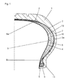
- Fig. 1 shows an inventively designed, at least over a certain mileage self-supporting at a pressure loss pneumatic vehicle tire in cross section.
- the tire has a tread 1, a belt bandage 2 having, for example, two belt layers, a carcass ply 3 embodied as a single-layer or two-ply, an airtight or substantially airtight inner layer 4, Bead areas with bead cores 5 and core profiles 6, side walls 7 and reinforcing profiles 8 on.
- the belt plies may consist in a known manner of embedded in a rubber compound reinforcements, in particular steel cords, which run parallel to each other within each layer, the steel cords in adjacent layers crossed to each other and with the circumferential direction of the tire an angle in the range between 15 ° and Include 28 °.
- the reinforcing profiles 8 are made of rubber and are arranged between the inner layer 4 and the carcass ply 3, they give the tire at a pressure loss self-carrying ability, so that a drive over a certain period of time and at reduced speed is possible.
- the carcass ply 3 circumscribes the bead cores 5 from inside to outside, is returned to itself and terminates at a height which may be radially inward or radially outward of the location with the largest cross-sectional width of the tire.
- Each reinforcing profile 8 extends between the inner layer 4 and the carcass ply 3 annularly on the inside of the side walls 7 and extends from just radially outside of the bead core 5 to below the lateral edge portions of the belt assembly 2. Their greatest width, the reinforcing profiles 8 approximately where the tire has its largest cross-sectional width.
- Reinforcing profiles 8 designed according to the invention are specially shaped on their insides which face the tire interior.
- the inside of each reinforcing profile 8 is provided with a rib structure 9 of alternately provided and oriented in the radial direction elevations 10 and depressions 11.
- the rib structure 9 occupies an annulus which is concentric with the outer circular rim 8a and the inner circular rim 8b of the reinforcing profile 8.
- all elevations 10 and all recesses 11 are each made coincident.
- the rib structure 9 is of great advantage for the bending stiffness of the reinforcing profiles 8, whereby, depending on the design, the rib structure 9 can reduce the rubber volume and thus the weight of the reinforcing profile 8, so that a reinforcing profile 8 with a lower weight and a smaller volume has the same flexural rigidity may have like a conventionally performed reinforcing profile with a higher weight and a higher volume. If a reinforcing profile 8 designed according to the invention is designed such that it has a weight corresponding to a conventional reinforcing profile, it has a significantly higher flexural rigidity.
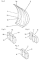
- Fig. 2 to Fig. 5 show embodiments of the rib structure 9 on the inner sides of a reinforcing profile 8.
- the rib structure consists of rounded elevations 10 (ribs) and depressions 11 located therebetween, the result is a wave shape in cross-section.
- the elevations 10 extend in this embodiment to the envelope of the inside.
- the extension of the depressions 11 into the profile 8 can vary insofar as the depressions 11 become progressively flatter in the direction of the edges 8 a, 8 b and have their greatest depth in the middle region of the profile 8.
- the embodiment is therefore particularly made such that the recesses 11 follow the cross-sectional shape of the profile 18.
- At the radial ends of the recesses 11 may be present a largely step-free outlet.
- Fig. 3 to 5 show views of sections of inventively designed reinforcing profiles 8.
- the rib structure 9 consists of arcuate recesses, in particular circular arc-shaped recesses, which adjoin one another almost directly, so that only narrow webs form the elevations 10 between the depressions 11.
- Fig. 4 shows a variant with a rib structure 9 of substantially in cross-section U-shaped recesses and complementary thereto and therefore rectangular executed elevations 10.
- the recesses 11 and the elevations 10 extend in cross-section along a zigzag shape and are therefore triangular in cross-section. With regard to the dimensioning of the recesses 11 or elevations 10 in the radial direction, the above explanations apply to all variants Fig. 2 ,
- the inner layer 4 located on the inside of the reinforcing profiles 8 is embodied and preformed in the manufacture of the tire such that it rests against the rib structure 9 on the inside of the reinforcing profile 8.
- a fabric made of textile or metallic reinforcing threads which is also applied to the surveys and following in the wells.
Landscapes
- Engineering & Computer Science (AREA)
- Mechanical Engineering (AREA)
- Tires In General (AREA)
- Pulleys (AREA)
- Turning (AREA)
Abstract
Description
- Die Erfindung betrifft einen Fahrzeugluftreifen in radialer Bauart mit einem profilierten Laufstreifen, einem Gürtelverband, einer Innenschicht, einer Karkasseinlage, Seitenwänden und mit im Bereich jeder Seitenwand zumindest je einem zwischen der Innenschicht und der Karkasseinlage eingebrachten, im Querschnitt mondsichelförmigen Verstärkungsprofil.
- Mit Verstärkungsprofilen in den Seitenwandbereichen versehene Fahrzeugluftreifen sind im Pannenfall, bei einem plötzlichen Druckverlust, zumindest über eine gewisse Laufleistung selbsttragend. Ein selbsttragender Reifen der eingangs genannten Art ist beispielsweise aus der
DE 2 331 530 A bekannt. Die aus Gummi bestehenden Verstärkungsprofile weisen eine Dicke von 3 % bis 15 % der maximalen Querschnittsbreite des unter Innendruck befindlichen Reifens auf. Bei den aus derDE 29 43 654 A bekannten Ausführungen sind in den Seitenwänden des Reifens mehrere Verstärkungsprofile eingebracht, die sich beispielsweise in ihrer Härte voneinander unterscheiden. - Nachdem die Verstärkungsprofile dem Reifen in den Seitenwänden eine hohe Biegesteifigkeit verleihen müssen, sind sie vergleichsweise voluminös auszuführen und tragen somit zum Gesamtgewicht des Reifen erheblich bei. Der Erfindung liegt daher die Aufgabe zu Grunde, bei einem Fahrzeugluftreifen der eingangs genannten Art die Verstärkungsprofile derart auszuführen, dass sie trotz merkbar geringerem Gewicht eine Biegesteifigkeit aufweisen, die zumindest der Biegesteifigkeit bekannter bzw. konventioneller Verstärkungsprofile entspricht.
- Gelöst wird die gestellte Aufgabe erfindungsgemäß dadurch, dass das Verstärkungsprofil an seiner der Innenschicht zugewandten Innenseite in radialer Richtung gerippt ausgeführt ist, wobei die Innenschicht der Rippenstruktur folgt.
- Durch die gerippte Ausführung der Verstärkungsprofile ist ihre Biegesteifigkeit bei gleichem Gewicht bzw. Volumen an Gummi im Vergleich zu herkömmlichen Verstärkungsprofilen deutlich höher. Werden erfindungsgemäß ausgeführte Verstärkungsprofile derart ausgelegt, dass ihre Biegesteifigkeit jener von Verstärkungsprofilen aus dem Stand der Technik entspricht, sind ihr Volumen und somit ihr Gewicht merklich geringer.
- Bei einer bevorzugten Ausführungsform der Erfindung ist die Rippenstruktur über die gesamte oder nahezu die gesamte Radialerstreckung des Verstärkungsprofils ausgebildet. Diese Maßnahme ist einerseits für einen optimalen Versteifungseffekt von Vorteil und bietet darüber hinaus die Möglichkeit, das Volumen und das Gewicht des Verstärkungsprofils optimal zu reduzieren.
- Nach einem weiteren Merkmal der Erfindung werden die Vertiefungen der Rippenstruktur derart ausgeführt, dass ihre Tiefe im radial mittleren Bereich des Verstärkungsprofils am größten ist. Auch diese Maßnahme wirkt sich auf das Versteifungsverhalten des Profils günstig aus.
- Um Instabilitäten an den Randabschnitten des Verstärkungsprofils zu vermeiden, ist es ferner von Vorteil, wenn die Tiefe der Vertiefungen der Rippenstruktur zu den radialen Enden des Verstärkungsprofils kontinuierlich geringer wird.
- Es gibt eine Vielzahl von Möglichkeiten, die Rippenstruktur gestalterisch auszuführen. Sämtlichen der in dieser Anmeldung beschriebenen und dargestellten Ausführungsvarianten ist es gemeinsam, dass sie sich gut fertigen lassen, bei der Herstellung mit der Innenschicht des Reifens gut verbinden lassen und die erwünschte Biegesteifigkeit des Verstärkungsprofils sicherstellen. Bei einer dieser bevorzugten Ausführungsvarianten besteht die Rippenstruktur aus im Querschnitt wellenförmig ausgeführten Erhebungen und Vertiefungen. Bei einer weiteren vorteilhaften Ausführungsvariante besteht die Rippenstruktur aus im Querschnitt bogenförmig geformten Vertiefungen mit Stegen als Erhebungen. Bei anderen Ausführungsvarianten ist vorgesehen, dass die Rippenstruktur aus im Querschnitt U-förmig geformten Vertiefungen und im Wesentlichen rechteckig geformten Erhebungen besteht oder im Querschnitt eine Zickzackform aufweist.
- Die Biegesteifigkeit des Verstärkungsprofils kann dadurch erhöht werden, dass auf der Rippenstruktur zusätzlich zumindest eine Verstärkungslage, insbesondere ein Gewebe, aufgebracht ist.
- Weitere Merkmale, Vorteile und Einzelheiten der Erfindung werden nun anhand der Zeichnung, die schematisch mehrere Ausführungsbeispiele darstellt, näher beschrieben. Dabei zeigen
-
Fig. 1 einen Querschnitt durch eine Hälfte eines Fahrzeugluftreifens für Personenkraftwagen und -
Fig. 2 bis Fig. 5 Ansichten von unterschiedlichen Ausführungsvarianten von Verstärkungsprofilen. -
Fig. 1 zeigt einen erfindungsgemäß ausgeführten, bei Druckverlust zumindest über eine gewisse Laufleistung selbsttragenden Fahrzeugluftreifen im Querschnitt. Der Reifen weist einen Laufstreifen 1, einen beispielsweise zwei Gürtellagen aufweisenden Gürtelverband 2, eine ein- oder zweilagig ausgeführte Karkasseinlage 3, eine luftdichte bzw. weitgehend luftdicht ausgeführte Innenschicht 4, Wulstbereiche mit Wulstkernen 5 und Kernprofilen 6, Seitenwände 7 und Verstärkungsprofile 8 auf. - Die Gürtellagen können in bekannter Weise aus in eine Gummimischung eingebetteten Festigkeitsträgern, insbesondere Stahlkorden, bestehen, welche innerhalb jeder Lage parallel zueinander verlaufen, wobei die Stahlkorde in einander benachbarten Lagen zueinander gekreuzt verlaufen und mit der Umfangsrichtung des Reifens einen Winkel im Bereich zwischen 15° und 28° einschließen. Die Verstärkungsprofile 8 bestehen aus Gummi und sind zwischen der Innenschicht 4 und der Karkasseinlage 3 angeordnet, sie verleihen dem Reifen bei Druckverlust eine Selbsttragefähigkeit, sodass eine Weiterfahrt über einen gewissen Zeitraum und bei verminderter Geschwindigkeit möglich ist.
- Die Karkasseinlage 3 umläuft die Wulstkerne 5 von innen nach außen, ist auf sich selbst rückgeführt und endet in einer Höhe, die radial innerhalb oder radial außerhalb der Stelle mit der größten Querschnittsbreite des Reifens liegen kann.
- Jedes Verstärkungsprofil 8 verläuft zwischen der Innenschicht 4 und der Karkasseinlage 3 kreisringförmig an der Innenseite der Seitenwände 7 und erstreckt sich von knapp radial außerhalb des Wulstkernes 5 bis unter die seitlichen Randabschnitte des Gürtelverbandes 2. Ihre größte Breite weisen die Verstärkungsprofile 8 etwa dort auf, wo der Reifen seine größte Querschnittsbreite besitzt.
- Erfindungsgemäß ausgeführte Verstärkungsprofile 8 sind an ihren Innenseiten, die dem Reifeninnenraum zugewandt sind, speziell geformt. Die Innenseite jedes Verstärkungsprofils 8 ist mit einer Rippenstruktur 9 aus abwechselnd vorgesehenen und in radialer Richtung orientierten Erhebungen 10 und Vertiefungen 11 versehen. Die Rippenstruktur 9 nimmt einen Kreisring ein, welcher konzentrisch zu dem äußeren kreisförmigen Rand 8a und zu dem inneren kreisförmigen Rand 8b des Verstärkungsprofils 8 verläuft. Zwischen der Rippenstruktur 9 und den Rändern 8a und 8b verbleiben schmale, vorzugsweise einige Millimeter breite kreisringförmige Randbereiche, die nicht strukturiert sind, um die Formstabilität der spitz zusammenlaufenden Randbereiche des Verstärkungsprofils 8 zu gewährleisten. Aus Gründen der Reifengleichförmigkeit sind sämtliche Erhebungen 10 und sämtliche Vertiefungen 11 jeweils übereinstimmend ausgeführt. Die Rippenstruktur 9 ist für die Biegesteifigkeit der Verstärkungsprofile 8 von großem Vorteil, wobei, je nach Ausführung, die Rippenstruktur 9 das Gummivolumen und damit das Gewicht des Verstärkungsprofils 8 verkleinern kann, sodass ein Verstärkungsprofil 8 mit einem geringeren Gewicht und einem geringeren Volumen die gleiche Biegesteifigkeit aufweisen kann wie ein herkömmlich ausgeführtes Verstärkungsprofil mit einem höherem Gewicht und einem höheren Volumen. Wird ein erfindungsgemäß ausgeführtes Verstärkungsprofil 8 derart ausgelegt, dass es ein einem üblichen Verstärkungsprofil entsprechendes Gewicht aufweist, weist es eine deutlich höhere Biegesteifigkeit auf.
-
Fig. 2 bis Fig. 5 zeigen Ausführungsvarianten der Rippenstruktur 9 an den Innenseiten eines Verstärkungsprofils 8. InFig. 2 besteht die Rippenstruktur aus gerundet ausgeführten Erhebungen 10 (Rippen) und dazwischen befindlichen Vertiefungen 11. Im Querschnitt ergibt sich daher eine Wellenform. Die Erhebungen 10 reichen bei dieser Ausführungsform bis zur Einhüllenden der Innenseite. Die Erstreckung der Vertiefungen 11 in das Profil 8 kann insofern variieren, als dass die Vertiefungen 11 in Richtung zu den Rändern 8a, 8b zunehmend flacher werden und ihre größte Tiefe im mittleren Bereich des Profils 8 aufweisen. Die Ausführung wird daher insbesondere so getroffen, dass die Vertiefungen 11 der Querschnittsform des Profils 18 folgen. An den radialen Enden der Vertiefungen 11 kann ein weitgehend stufenfreier Auslauf vorliegen. -
Fig. 3 bis 5 zeigen Ansichten von Ausschnitten aus erfindungsgemäß ausgeführten Verstärkungsprofilen 8. Bei der inFig. 3 gezeigten Ausführungsform besteht die Rippenstruktur 9 aus im Querschnitt bogenförmigen, insbesondere kreisbogenförmigen Vertiefungen, die nahezu unmittelbar aneinander anschließen, sodass zwischen den Vertiefungen 11 nur schmale Stege die Erhebungen 10 bilden.Fig. 4 zeigt eine Ausführungsvariante mit einer Rippenstruktur 9 aus im Wesentlichen im Querschnitt U-förmigen Vertiefungen und komplementär dazu und daher rechteckförmig ausgeführten Erhebungen 10. Bei der inFig. 5 gezeigten Ausführungsvariante verlaufen die Vertiefungen 11 und die Erhebungen 10 im Querschnitt entlang einer Zickzack-Form und sind daher im Querschnitt dreieckförmig. Bei sämtlichen Ausführungsvarianten gelten bezüglich der Dimensionierung der Vertiefungen 11 bzw. Erhebungen 10 in radialer Richtung die obigen Ausführungen zuFig. 2 . - Die auf der Innenseite der Verstärkungsprofile 8 befindliche Innenschicht 4 wird derart ausgeführt und bei der Herstellung des Reifens derart vorgeformt, dass sie der Rippenstruktur 9 an der Innenseite des Verstärkungsprofiles 8 folgend anliegt. Gemäß einer weiteren, nicht gezeigten Ausführungsvariante kann auf die Innenseite der Verstärkungsprofile 8 ein Gewebe aus textilen oder metallischen Verstärkungsfäden aufgebracht sein, welches ebenfalls den Erhebungen und in den Vertiefungen folgend aufgebracht ist.
- Es ist ferner möglich, erfindungsgemäß ausgeführte Verstärkungsprofile mehrteilig auszuführen oder in Kombination mit weiteren Verstärkungsprofilen zu verwenden.
-
- 1
- Laufstreifen
- 2
- Gürtelverband
- 3
- Karkasseinlage
- 4
- Innenschicht
- 5
- Wulstkerne
- 6
- Kernprofile
- 7
- Seitenwand
- 8
- Verstärkungsprofile
- 8a
- Ränder
- 8b
- Ränder
- 9
- Rippenstruktur
- 10
- Erhebungen
- 11
- Vertiefungen
Claims (9)
- Fahrzeugluftreifen in radialer Bauart mit einem profilierten Laufstreifen (1), einem Gürtelverband (2), einer Innenschicht (4), einer Karkasseinlage (3), Seitenwänden (7) und mit im Bereich jeder Seitenwand (7) zumindest je einem zwischen der Innenschicht (4) und der Karkasseinlage (3) eingebrachten, im Querschnitt mondsichelförmigen Verstärkungsprofil (8),
dadurch gekennzeichnet,
dass das Verstärkungsprofil (8) an seiner der Innenschicht (4) zugewandten Innenseite in radialer Richtung gerippt ausgeführt ist, wobei die Innenschicht (4) der Rippenstruktur (9) folgt. - Fahrzeugluftreifen nach Anspruch 1, dadurch gekennzeichnet, dass die Rippenstruktur (9) über die gesamte oder nahezu die gesamte Radialerstreckung des Verstärkungsprofils (8) ausgebildet ist.
- Fahrzeugluftreifen nach Anspruch 1 oder 2, dadurch gekennzeichnet, dass die Vertiefungen (11) der Rippenstruktur (9) eine Tiefe aufweisen, die im radial mittleren Bereich des Verstärkungsprofils (8) am größten ist.
- Fahrzeugluftreifen nach einem der Ansprüche 1 bis 3, dadurch gekennzeichnet, dass die Tiefe der Vertiefungen (11) der Rippenstruktur (9) zu den radialen Enden des Verstärkungsprofils (8) kontinuierlich geringer wird.
- Fahrzeugluftreifen nach einem der Ansprüche 1 bis 4, dadurch gekennzeichnet, dass die Rippenstruktur (9) aus im Querschnitt wellenförmig ausgeführten Erhebungen (10) und Vertiefungen (11) besteht.
- Fahrzeugluftreifen nach einem der Ansprüche 1 bis 4, dadurch gekennzeichnet, dass die Rippenstruktur (9) aus im Querschnitt bogenförmig geformten Vertiefungen (11) mit Stegen als Erhebungen (10) besteht.
- Fahrzeugluftreifen nach einem der Ansprüche 1 bis 4, dadurch gekennzeichnet, dass die Rippenstruktur (9) aus im Querschnitt U-förmig geformten Vertiefungen (11) und rechteckig geformten Erhebungen (10) besteht.
- Fahrzeugluftreifen nach einem der Ansprüche 1 bis 4, dadurch gekennzeichnet, dass die Rippenstruktur (9) im Querschnitt eine Zickzack-Form aufweist.
- Fahrzeugluftreifen nach einem der Ansprüche 1 bis 8, dadurch gekennzeichnet, dass auf der Rippenstruktur (9) eine Verstärkungslage, insbesondere ein Gewebe, aufgebracht ist.
Applications Claiming Priority (1)
| Application Number | Priority Date | Filing Date | Title |
|---|---|---|---|
| DE102007015352A DE102007015352A1 (de) | 2007-03-30 | 2007-03-30 | Fahrzeugluftreifen |
Publications (2)
| Publication Number | Publication Date |
|---|---|
| EP1974959A1 true EP1974959A1 (de) | 2008-10-01 |
| EP1974959B1 EP1974959B1 (de) | 2009-12-09 |
Family
ID=39580049
Family Applications (1)
| Application Number | Title | Priority Date | Filing Date |
|---|---|---|---|
| EP08151147A Not-in-force EP1974959B1 (de) | 2007-03-30 | 2008-02-07 | Fahrzeugluftreifen |
Country Status (3)
| Country | Link |
|---|---|
| EP (1) | EP1974959B1 (de) |
| AT (1) | ATE451258T1 (de) |
| DE (2) | DE102007015352A1 (de) |
Cited By (3)
| Publication number | Priority date | Publication date | Assignee | Title |
|---|---|---|---|---|
| EP2565058A1 (de) * | 2011-09-02 | 2013-03-06 | The Goodyear Tire & Rubber Company | Selbsttragender Luftreifen |
| EP3020570A4 (de) * | 2013-07-11 | 2016-07-13 | Bridgestone Corp | Luftreifen |
| JP2019151301A (ja) * | 2018-03-06 | 2019-09-12 | 横浜ゴム株式会社 | 空気入りタイヤ |
Citations (8)
| Publication number | Priority date | Publication date | Assignee | Title |
|---|---|---|---|---|
| GB867103A (en) * | 1957-06-13 | 1961-05-03 | Metzeler Gummiwerke Ag | Pneumatic vehicle tyres for employment with or without inner tubes |
| NL7203518A (de) * | 1971-03-20 | 1972-09-22 | ||
| DE2331530A1 (de) | 1972-06-21 | 1974-01-03 | Bridgestone Tire Co Ltd | Sicherheits-luftreifen |
| FR2395851A1 (fr) * | 1977-06-27 | 1979-01-26 | Goodyear Tire & Rubber | Pneumatique de securite perfectionne pour vehicule |
| DE2943654A1 (de) | 1978-10-30 | 1980-05-14 | Bridgestone Tire Co Ltd | Sicherheits-luftreifen |
| WO2001025032A1 (en) | 1999-09-30 | 2001-04-12 | The Goodyear Tire & Rubber Company | Runflat tire with sawtooth shaped insert |
| WO2001043995A1 (en) * | 1999-12-16 | 2001-06-21 | The Gooyear Tire & Rubber Company | Variable-stiffness wedge inserts for runflat tires |
| US20060060281A1 (en) * | 2004-09-13 | 2006-03-23 | Kirby James M | Apparatus and method of enhancing run-flat travel for pneumatic tires |
-
2007
- 2007-03-30 DE DE102007015352A patent/DE102007015352A1/de not_active Withdrawn
-
2008
- 2008-02-07 DE DE502008000233T patent/DE502008000233D1/de active Active
- 2008-02-07 EP EP08151147A patent/EP1974959B1/de not_active Not-in-force
- 2008-02-07 AT AT08151147T patent/ATE451258T1/de active
Patent Citations (9)
| Publication number | Priority date | Publication date | Assignee | Title |
|---|---|---|---|---|
| GB867103A (en) * | 1957-06-13 | 1961-05-03 | Metzeler Gummiwerke Ag | Pneumatic vehicle tyres for employment with or without inner tubes |
| NL7203518A (de) * | 1971-03-20 | 1972-09-22 | ||
| DE2331530A1 (de) | 1972-06-21 | 1974-01-03 | Bridgestone Tire Co Ltd | Sicherheits-luftreifen |
| FR2395851A1 (fr) * | 1977-06-27 | 1979-01-26 | Goodyear Tire & Rubber | Pneumatique de securite perfectionne pour vehicule |
| DE2943654A1 (de) | 1978-10-30 | 1980-05-14 | Bridgestone Tire Co Ltd | Sicherheits-luftreifen |
| GB2033316A (en) * | 1978-10-30 | 1980-05-21 | Bridgestone Tire Co Ltd | Run flat pneumatic tyres |
| WO2001025032A1 (en) | 1999-09-30 | 2001-04-12 | The Goodyear Tire & Rubber Company | Runflat tire with sawtooth shaped insert |
| WO2001043995A1 (en) * | 1999-12-16 | 2001-06-21 | The Gooyear Tire & Rubber Company | Variable-stiffness wedge inserts for runflat tires |
| US20060060281A1 (en) * | 2004-09-13 | 2006-03-23 | Kirby James M | Apparatus and method of enhancing run-flat travel for pneumatic tires |
Cited By (5)
| Publication number | Priority date | Publication date | Assignee | Title |
|---|---|---|---|---|
| EP2565058A1 (de) * | 2011-09-02 | 2013-03-06 | The Goodyear Tire & Rubber Company | Selbsttragender Luftreifen |
| US8573272B2 (en) | 2011-09-02 | 2013-11-05 | The Goodyear Tire & Rubber Company | Self-supporting pneumatic tire |
| EP3020570A4 (de) * | 2013-07-11 | 2016-07-13 | Bridgestone Corp | Luftreifen |
| JP2019151301A (ja) * | 2018-03-06 | 2019-09-12 | 横浜ゴム株式会社 | 空気入りタイヤ |
| JP7040139B2 (ja) | 2018-03-06 | 2022-03-23 | 横浜ゴム株式会社 | 空気入りタイヤ |
Also Published As
| Publication number | Publication date |
|---|---|
| DE502008000233D1 (de) | 2010-01-21 |
| ATE451258T1 (de) | 2009-12-15 |
| DE102007015352A1 (de) | 2008-10-02 |
| EP1974959B1 (de) | 2009-12-09 |
Similar Documents
| Publication | Publication Date | Title |
|---|---|---|
| EP2627523B1 (de) | Fahrzeugluftreifen | |
| EP3088209B1 (de) | Fahrzeugluftreifen | |
| EP1974959B1 (de) | Fahrzeugluftreifen | |
| EP0881105B1 (de) | Fahrzeugluftreifen | |
| EP1901930B1 (de) | Fahrzeugluftreifen mit verstärkter wulstkonstruktion | |
| EP3215374B1 (de) | Fahrzeugluftreifen | |
| DE102004059771B4 (de) | Fahrzeugluftreifen und Verfahren zur Herstellung | |
| EP1982849B1 (de) | Fahrzeugluftreifen mit Notlaufeigenschaften | |
| WO2017080692A1 (de) | Fahrzeugluftreifen | |
| DE102014222303B4 (de) | Fahrzeugluftreifen mit asymmetrischer Karkasse | |
| DE102004059772B4 (de) | Fahrzeugluftreifen | |
| EP3271194B1 (de) | Fahrzeugluftreifen | |
| EP1816012B1 (de) | Fahrzeugnotlaufreifen mit Seitenwandverstärkungsprofilen und Verfahren zur Herstellung der Profile | |
| DE102007009101B4 (de) | Fahrzeugluftreifen | |
| DE102008037614B4 (de) | Fahrzeugluftreifen | |
| DE102004060468A1 (de) | Fahrzeugluftreifen | |
| EP3308976B1 (de) | Fahrzeugluftreifen | |
| DE102005041937A1 (de) | Fahrzeugluftreifen und Verfahren zur Herstellung | |
| DE102024210030A1 (de) | Fahrzeugluftreifen | |
| EP1782968A2 (de) | Fahrzeugluftreifen | |
| EP2918425B1 (de) | Fahrzeugluftreifen | |
| EP1535763B1 (de) | Verfahren zur Herstellung eines Fahrzeugluftreifens | |
| DE102020213505A1 (de) | Fahrzeugluftreifen | |
| DE102012106309A1 (de) | Fahrzeugluftreifen mit Notlaufeigenschaften | |
| DE102008004478A1 (de) | Fahrzeugluftreifen mit Notlaufeigenschaften bei Druckluftverlust |
Legal Events
| Date | Code | Title | Description |
|---|---|---|---|
| PUAI | Public reference made under article 153(3) epc to a published international application that has entered the european phase |
Free format text: ORIGINAL CODE: 0009012 |
|
| AK | Designated contracting states |
Kind code of ref document: A1 Designated state(s): AT BE BG CH CY CZ DE DK EE ES FI FR GB GR HR HU IE IS IT LI LT LU LV MC MT NL NO PL PT RO SE SI SK TR |
|
| AX | Request for extension of the european patent |
Extension state: AL BA MK RS |
|
| RIN1 | Information on inventor provided before grant (corrected) |
Inventor name: FIDAN, SADDETTIN |
|
| 17P | Request for examination filed |
Effective date: 20090401 |
|
| 17Q | First examination report despatched |
Effective date: 20090430 |
|
| AKX | Designation fees paid |
Designated state(s): AT BE BG CH CY CZ DE DK EE ES FI FR GB GR HR HU IE IS IT LI LT LU LV MC MT NL NO PL PT RO SE SI SK TR |
|
| GRAP | Despatch of communication of intention to grant a patent |
Free format text: ORIGINAL CODE: EPIDOSNIGR1 |
|
| GRAS | Grant fee paid |
Free format text: ORIGINAL CODE: EPIDOSNIGR3 |
|
| GRAA | (expected) grant |
Free format text: ORIGINAL CODE: 0009210 |
|
| AK | Designated contracting states |
Kind code of ref document: B1 Designated state(s): AT BE BG CH CY CZ DE DK EE ES FI FR GB GR HR HU IE IS IT LI LT LU LV MC MT NL NO PL PT RO SE SI SK TR |
|
| REG | Reference to a national code |
Ref country code: GB Ref legal event code: FG4D Free format text: NOT ENGLISH |
|
| REG | Reference to a national code |
Ref country code: CH Ref legal event code: EP |
|
| REG | Reference to a national code |
Ref country code: IE Ref legal event code: FG4D |
|
| REF | Corresponds to: |
Ref document number: 502008000233 Country of ref document: DE Date of ref document: 20100121 Kind code of ref document: P |
|
| REG | Reference to a national code |
Ref country code: NL Ref legal event code: VDEP Effective date: 20091209 |
|
| PG25 | Lapsed in a contracting state [announced via postgrant information from national office to epo] |
Ref country code: FI Free format text: LAPSE BECAUSE OF FAILURE TO SUBMIT A TRANSLATION OF THE DESCRIPTION OR TO PAY THE FEE WITHIN THE PRESCRIBED TIME-LIMIT Effective date: 20091209 Ref country code: LT Free format text: LAPSE BECAUSE OF FAILURE TO SUBMIT A TRANSLATION OF THE DESCRIPTION OR TO PAY THE FEE WITHIN THE PRESCRIBED TIME-LIMIT Effective date: 20091209 Ref country code: NO Free format text: LAPSE BECAUSE OF FAILURE TO SUBMIT A TRANSLATION OF THE DESCRIPTION OR TO PAY THE FEE WITHIN THE PRESCRIBED TIME-LIMIT Effective date: 20100309 Ref country code: SE Free format text: LAPSE BECAUSE OF FAILURE TO SUBMIT A TRANSLATION OF THE DESCRIPTION OR TO PAY THE FEE WITHIN THE PRESCRIBED TIME-LIMIT Effective date: 20091209 |
|
| LTIE | Lt: invalidation of european patent or patent extension |
Effective date: 20091209 |
|
| PG25 | Lapsed in a contracting state [announced via postgrant information from national office to epo] |
Ref country code: LV Free format text: LAPSE BECAUSE OF FAILURE TO SUBMIT A TRANSLATION OF THE DESCRIPTION OR TO PAY THE FEE WITHIN THE PRESCRIBED TIME-LIMIT Effective date: 20091209 Ref country code: PL Free format text: LAPSE BECAUSE OF FAILURE TO SUBMIT A TRANSLATION OF THE DESCRIPTION OR TO PAY THE FEE WITHIN THE PRESCRIBED TIME-LIMIT Effective date: 20091209 Ref country code: HR Free format text: LAPSE BECAUSE OF FAILURE TO SUBMIT A TRANSLATION OF THE DESCRIPTION OR TO PAY THE FEE WITHIN THE PRESCRIBED TIME-LIMIT Effective date: 20091209 Ref country code: SI Free format text: LAPSE BECAUSE OF FAILURE TO SUBMIT A TRANSLATION OF THE DESCRIPTION OR TO PAY THE FEE WITHIN THE PRESCRIBED TIME-LIMIT Effective date: 20091209 |
|
| REG | Reference to a national code |
Ref country code: IE Ref legal event code: FD4D |
|
| PG25 | Lapsed in a contracting state [announced via postgrant information from national office to epo] |
Ref country code: ES Free format text: LAPSE BECAUSE OF FAILURE TO SUBMIT A TRANSLATION OF THE DESCRIPTION OR TO PAY THE FEE WITHIN THE PRESCRIBED TIME-LIMIT Effective date: 20100320 Ref country code: IE Free format text: LAPSE BECAUSE OF FAILURE TO SUBMIT A TRANSLATION OF THE DESCRIPTION OR TO PAY THE FEE WITHIN THE PRESCRIBED TIME-LIMIT Effective date: 20091209 Ref country code: RO Free format text: LAPSE BECAUSE OF FAILURE TO SUBMIT A TRANSLATION OF THE DESCRIPTION OR TO PAY THE FEE WITHIN THE PRESCRIBED TIME-LIMIT Effective date: 20091209 Ref country code: IS Free format text: LAPSE BECAUSE OF FAILURE TO SUBMIT A TRANSLATION OF THE DESCRIPTION OR TO PAY THE FEE WITHIN THE PRESCRIBED TIME-LIMIT Effective date: 20100409 Ref country code: BG Free format text: LAPSE BECAUSE OF FAILURE TO SUBMIT A TRANSLATION OF THE DESCRIPTION OR TO PAY THE FEE WITHIN THE PRESCRIBED TIME-LIMIT Effective date: 20100309 Ref country code: NL Free format text: LAPSE BECAUSE OF FAILURE TO SUBMIT A TRANSLATION OF THE DESCRIPTION OR TO PAY THE FEE WITHIN THE PRESCRIBED TIME-LIMIT Effective date: 20091209 Ref country code: EE Free format text: LAPSE BECAUSE OF FAILURE TO SUBMIT A TRANSLATION OF THE DESCRIPTION OR TO PAY THE FEE WITHIN THE PRESCRIBED TIME-LIMIT Effective date: 20091209 |
|
| BERE | Be: lapsed |
Owner name: CONTINENTAL A.G. Effective date: 20100228 |
|
| PG25 | Lapsed in a contracting state [announced via postgrant information from national office to epo] |
Ref country code: SK Free format text: LAPSE BECAUSE OF FAILURE TO SUBMIT A TRANSLATION OF THE DESCRIPTION OR TO PAY THE FEE WITHIN THE PRESCRIBED TIME-LIMIT Effective date: 20091209 Ref country code: CZ Free format text: LAPSE BECAUSE OF FAILURE TO SUBMIT A TRANSLATION OF THE DESCRIPTION OR TO PAY THE FEE WITHIN THE PRESCRIBED TIME-LIMIT Effective date: 20091209 |
|
| PLBE | No opposition filed within time limit |
Free format text: ORIGINAL CODE: 0009261 |
|
| STAA | Information on the status of an ep patent application or granted ep patent |
Free format text: STATUS: NO OPPOSITION FILED WITHIN TIME LIMIT |
|
| PG25 | Lapsed in a contracting state [announced via postgrant information from national office to epo] |
Ref country code: GR Free format text: LAPSE BECAUSE OF FAILURE TO SUBMIT A TRANSLATION OF THE DESCRIPTION OR TO PAY THE FEE WITHIN THE PRESCRIBED TIME-LIMIT Effective date: 20100310 Ref country code: MC Free format text: LAPSE BECAUSE OF NON-PAYMENT OF DUE FEES Effective date: 20100301 Ref country code: CY Free format text: LAPSE BECAUSE OF FAILURE TO SUBMIT A TRANSLATION OF THE DESCRIPTION OR TO PAY THE FEE WITHIN THE PRESCRIBED TIME-LIMIT Effective date: 20091209 |
|
| 26N | No opposition filed |
Effective date: 20100910 |
|
| REG | Reference to a national code |
Ref country code: FR Ref legal event code: ST Effective date: 20101029 |
|
| PG25 | Lapsed in a contracting state [announced via postgrant information from national office to epo] |
Ref country code: FR Free format text: LAPSE BECAUSE OF NON-PAYMENT OF DUE FEES Effective date: 20100301 Ref country code: DK Free format text: LAPSE BECAUSE OF FAILURE TO SUBMIT A TRANSLATION OF THE DESCRIPTION OR TO PAY THE FEE WITHIN THE PRESCRIBED TIME-LIMIT Effective date: 20091209 |
|
| PG25 | Lapsed in a contracting state [announced via postgrant information from national office to epo] |
Ref country code: BE Free format text: LAPSE BECAUSE OF NON-PAYMENT OF DUE FEES Effective date: 20100228 |
|
| PG25 | Lapsed in a contracting state [announced via postgrant information from national office to epo] |
Ref country code: IT Free format text: LAPSE BECAUSE OF FAILURE TO SUBMIT A TRANSLATION OF THE DESCRIPTION OR TO PAY THE FEE WITHIN THE PRESCRIBED TIME-LIMIT Effective date: 20091209 |
|
| PG25 | Lapsed in a contracting state [announced via postgrant information from national office to epo] |
Ref country code: MT Free format text: LAPSE BECAUSE OF FAILURE TO SUBMIT A TRANSLATION OF THE DESCRIPTION OR TO PAY THE FEE WITHIN THE PRESCRIBED TIME-LIMIT Effective date: 20091209 |
|
| PG25 | Lapsed in a contracting state [announced via postgrant information from national office to epo] |
Ref country code: HU Free format text: LAPSE BECAUSE OF FAILURE TO SUBMIT A TRANSLATION OF THE DESCRIPTION OR TO PAY THE FEE WITHIN THE PRESCRIBED TIME-LIMIT Effective date: 20100610 Ref country code: PT Free format text: LAPSE BECAUSE OF FAILURE TO SUBMIT A TRANSLATION OF THE DESCRIPTION OR TO PAY THE FEE WITHIN THE PRESCRIBED TIME-LIMIT Effective date: 20100509 Ref country code: LU Free format text: LAPSE BECAUSE OF NON-PAYMENT OF DUE FEES Effective date: 20100207 |
|
| REG | Reference to a national code |
Ref country code: CH Ref legal event code: PL |
|
| GBPC | Gb: european patent ceased through non-payment of renewal fee |
Effective date: 20120207 |
|
| PG25 | Lapsed in a contracting state [announced via postgrant information from national office to epo] |
Ref country code: LI Free format text: LAPSE BECAUSE OF NON-PAYMENT OF DUE FEES Effective date: 20120229 Ref country code: CH Free format text: LAPSE BECAUSE OF NON-PAYMENT OF DUE FEES Effective date: 20120229 Ref country code: TR Free format text: LAPSE BECAUSE OF FAILURE TO SUBMIT A TRANSLATION OF THE DESCRIPTION OR TO PAY THE FEE WITHIN THE PRESCRIBED TIME-LIMIT Effective date: 20091209 |
|
| PG25 | Lapsed in a contracting state [announced via postgrant information from national office to epo] |
Ref country code: GB Free format text: LAPSE BECAUSE OF NON-PAYMENT OF DUE FEES Effective date: 20120207 |
|
| REG | Reference to a national code |
Ref country code: AT Ref legal event code: MM01 Ref document number: 451258 Country of ref document: AT Kind code of ref document: T Effective date: 20130207 |
|
| PG25 | Lapsed in a contracting state [announced via postgrant information from national office to epo] |
Ref country code: AT Free format text: LAPSE BECAUSE OF NON-PAYMENT OF DUE FEES Effective date: 20130207 |
|
| PGFP | Annual fee paid to national office [announced via postgrant information from national office to epo] |
Ref country code: DE Payment date: 20240229 Year of fee payment: 17 |
|
| REG | Reference to a national code |
Ref country code: DE Ref legal event code: R119 Ref document number: 502008000233 Country of ref document: DE |
|
| PG25 | Lapsed in a contracting state [announced via postgrant information from national office to epo] |
Ref country code: DE Free format text: LAPSE BECAUSE OF NON-PAYMENT OF DUE FEES Effective date: 20250902 |