EP1974512B1 - Rekursive berechnung einer kanalmatrix für einen mimo-entzerrer - Google Patents
Rekursive berechnung einer kanalmatrix für einen mimo-entzerrer Download PDFInfo
- Publication number
- EP1974512B1 EP1974512B1 EP07716730.2A EP07716730A EP1974512B1 EP 1974512 B1 EP1974512 B1 EP 1974512B1 EP 07716730 A EP07716730 A EP 07716730A EP 1974512 B1 EP1974512 B1 EP 1974512B1
- Authority
- EP
- European Patent Office
- Prior art keywords
- matrix
- module
- data
- training
- training fields
- Prior art date
- Legal status (The legal status is an assumption and is not a legal conclusion. Google has not performed a legal analysis and makes no representation as to the accuracy of the status listed.)
- Active
Links
Images


Classifications
-
- H—ELECTRICITY
- H04—ELECTRIC COMMUNICATION TECHNIQUE
- H04B—TRANSMISSION
- H04B7/00—Radio transmission systems, i.e. using radiation field
- H04B7/02—Diversity systems; Multi-antenna system, i.e. transmission or reception using multiple antennas
- H04B7/04—Diversity systems; Multi-antenna system, i.e. transmission or reception using multiple antennas using two or more spaced independent antennas
- H04B7/06—Diversity systems; Multi-antenna system, i.e. transmission or reception using multiple antennas using two or more spaced independent antennas at the transmitting station
- H04B7/0613—Diversity systems; Multi-antenna system, i.e. transmission or reception using multiple antennas using two or more spaced independent antennas at the transmitting station using simultaneous transmission
- H04B7/0684—Diversity systems; Multi-antenna system, i.e. transmission or reception using multiple antennas using two or more spaced independent antennas at the transmitting station using simultaneous transmission using different training sequences per antenna
-
- H—ELECTRICITY
- H04—ELECTRIC COMMUNICATION TECHNIQUE
- H04L—TRANSMISSION OF DIGITAL INFORMATION, e.g. TELEGRAPHIC COMMUNICATION
- H04L25/00—Baseband systems
- H04L25/02—Details ; arrangements for supplying electrical power along data transmission lines
- H04L25/03—Shaping networks in transmitter or receiver, e.g. adaptive shaping networks
-
- H—ELECTRICITY
- H04—ELECTRIC COMMUNICATION TECHNIQUE
- H04L—TRANSMISSION OF DIGITAL INFORMATION, e.g. TELEGRAPHIC COMMUNICATION
- H04L25/00—Baseband systems
- H04L25/02—Details ; arrangements for supplying electrical power along data transmission lines
- H04L25/0202—Channel estimation
- H04L25/0224—Channel estimation using sounding signals
-
- H—ELECTRICITY
- H04—ELECTRIC COMMUNICATION TECHNIQUE
- H04B—TRANSMISSION
- H04B7/00—Radio transmission systems, i.e. using radiation field
- H04B7/02—Diversity systems; Multi-antenna system, i.e. transmission or reception using multiple antennas
- H04B7/04—Diversity systems; Multi-antenna system, i.e. transmission or reception using multiple antennas using two or more spaced independent antennas
- H04B7/0413—MIMO systems
-
- H—ELECTRICITY
- H04—ELECTRIC COMMUNICATION TECHNIQUE
- H04L—TRANSMISSION OF DIGITAL INFORMATION, e.g. TELEGRAPHIC COMMUNICATION
- H04L25/00—Baseband systems
- H04L25/02—Details ; arrangements for supplying electrical power along data transmission lines
- H04L25/0202—Channel estimation
- H04L25/024—Channel estimation channel estimation algorithms
- H04L25/0242—Channel estimation channel estimation algorithms using matrix methods
- H04L25/0246—Channel estimation channel estimation algorithms using matrix methods with factorisation
-
- H—ELECTRICITY
- H04—ELECTRIC COMMUNICATION TECHNIQUE
- H04L—TRANSMISSION OF DIGITAL INFORMATION, e.g. TELEGRAPHIC COMMUNICATION
- H04L25/00—Baseband systems
- H04L25/02—Details ; arrangements for supplying electrical power along data transmission lines
- H04L25/03—Shaping networks in transmitter or receiver, e.g. adaptive shaping networks
- H04L25/03006—Arrangements for removing intersymbol interference
- H04L2025/0335—Arrangements for removing intersymbol interference characterised by the type of transmission
- H04L2025/03426—Arrangements for removing intersymbol interference characterised by the type of transmission transmission using multiple-input and multiple-output channels
Definitions
- the present disclosure relates to channel estimation in a wireless communication system.
- Some multiple input, multiple output (MIMO) wireless communication systems can estimate channel conditions, or gains, in the communication path between the transmitting and receiving antennas.
- the channel estimation process can include transmitting known training symbols, receiving the known training symbols, and processing the received symbols to estimate the channel conditions. The estimation is based on differences between the known training symbols and the received symbols. Information regarding the channel conditions can then be used to program coefficients of an equalizer of the receiver. The equalizer then compensates for the channel conditions.
- FIG. 1 an example is shown of a MIMO communication system 10 that complies with the Institute of Electrical and Electronics Engineers (IEEE) 802.11n specification.
- a transmitter module 12 communicates with a receiver module 14 via a wireless communication channel 16.
- a matrix H represents signal gains through channel 16.
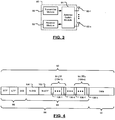
- Transmitter module 12 periodically generates a plurality of long training fields (LTFs) 18-1, ..., 18-j, referred to collectively as LTFs 18.
- LTFs long training fields
- Each LTF 18 includes a plurality of training symbols 20-1, ..., 20-k, referred to collectively as training symbols 20.
- a multiplier module 22 multiplies each training symbol 20 by a corresponding column of a preamble steering matrix P.
- a number of rows n of matrix P corresponds with a number of transmit antennas 26-1, ..., 26-n, collectively referred to as antennas 26.
- the number of columns j of matrix P corresponds with the number of LTFs 18.
- Matrix P assures the orthogonality of training symbols 20 as they are transmitted from antennas 26.
- Receiver module 14 includes receiver antennas 30-1, ..., 30-n, collectively referred to as antennas 30, that receive the training symbols via channel 16. After receiving all of the training symbols, receiver module 14 generates matrix H based on known training symbols 20, matrix P, and the received training symbols. Receiver module 14 can then use matrix H to adjust coefficients of an internal equalization module for signals from antennas 30. It is generally desirable for receiver module 14 to generate matrix H as quickly as possible.
- H est represents an estimation of matrix H.
- y H est P -1 x + n, where x represents transmitted data symbols.
- the ZF solution is applied to the matrix H est P -1 .
- y H est P -1 x + n.
- Receiver module 14 uses each LTF 18 to estimate a column of matrix H est .
- Matrix H can therefore be estimated by waiting until all columns have been estimated and then estimating the matrixH est P -1 .
- Receiver module 14 can then perform orthogonal-triangular decomposition (QR) on H est P -1 , i.e QR ( H est P -1 ) .
- QR orthogonal-triangular decomposition
- the computational density increases to the order of n 3 , i.e. O(n 3 ).
- O(n 3 ) the hardware burden would also increase based on O(n 3 ).
- US 2005/185738 A1 relates to a method for payload-based channel estimation of a wireless channel which begins by receiving a frame via the wireless communication channel.
- the frame includes a training sequence, a frame information section, and a plurality of time sequential data payload sections. As the frame is being received, the method continues by determining a channel estimation based on the training sequence.
- US 2005/249303 A1 relates to a method and system enhancing transmission efficiency by decreasing regions of reference signals which are attached to transmit packets from a transmitter during bidirectional SVD-MIMO communication.
- the transmitter transmits user data following a reference signal.
- the receiver acquires a channel matrix, based on the reference signal attached preceding the user data, receives the user data, while weighting the data with receive weights derived from the channel matrix, adaptively estimates the channel matrix H as long as the user data is being received, and obtains transmit weights V' for transmitting user data in the reverse direction from an adaptively estimated channel matrix H'.
- the transmitter transmits sub-carriers weighted by the matrix V of transmit antenna weighting factors and the receiver receives the sub-carriers that are then weighted by the matrix UH of receive antenna weighting factors.
- the receiver feeds back the transmit weight matrix V to the transmitter and the transmitter then transmits a reference signal weighted with the matrix V to the receiver before the receiver acquires the channel matrix again.
- the receiver can acquire a channel matrix HV from the reference signal weighted by V.
- EP 1 566 917 A relates to adaptive MIMO systems.
- an adaptive MIMO communication system comprising a MIMO transmitter, a MIMO receiver, and having a feedback path from said receiver to said transmitter.
- the decomposition of the MIMO channel estimate matrix can be used as a precursor to both determining a channel condition or metric and decoding received data, and decomposition of the channel estimate matrix can proceed in parallel with a determination of the channel estimation matrix itself.
- MIMO decoding generally relies upon some form of factorization of the matrix channel estimate, such as QR factorization or SVD factorization, to estimate the transmitted symbols.
- Q can be easily inverted as its transpose is the inverse from definition.
- the MIMO decoder can use a straightforward back-substitution method with quantization for estimating each symbol in the block, whilst simplifying the channel metric computation process.
- the QR or other decomposition may be performed in parallel with the channel estimation procedure.
- the channel estimation may be performed column-by-column and the QR decomposition procedure may also allow decomposition on a column-by-column basis.
- a receiver module includes an input that receives a data message from a wireless communication channel.
- the data message has a plurality of training fields and data.
- a channel estimator module recursively estimates a matrix H that represents the channel based on the plurality of training fields. The recursive estimation is performed as the plurality of training fields are being received.
- An equalizer module applies coefficients to the data based on the matrix H.
- the channel estimator module begins the recursive estimation upon receiving a first one of the training fields and finishes the recursive estimation upon receiving a final one of the plurality of training fields.
- the channel estimator module estimates the matrix H based on a matrix P.
- the plurality of training symbols are processed in accordance with the matrix P prior to being transmitted to the receiver module.
- the recursive estimation of matrix H includes recursively estimating a matrix H est based on the plurality of training fields and estimating matrix H based on an inverse of matrix P and a final value of the matrix H est . Each iteration of the recursive estimation of matrix H est occurs after receiving a corresponding one of the plurality of training fields.
- the receiver module further includes a plurality of FFT modules that convert the data from time domain signals to frequency domain signals. Respective outputs of the plurality of FFT modules communicate with respective inputs of the equalizer module.
- the receiver module includes a Viterbi decoder module that generates data symbols based on the frequency domain signals communicated from an output of the equalizer module.
- the plurality of training fields are compliant with IEEE 802.11n.
- a transceiver module includes the receiver module and further includes a transmitter module.
- the transmitter module generates training symbols that are to be included in the plurality of training fields and includes a multiplier module that multiplies the training symbols by a matrix P.
- the matrix P has a condition number equal to 1.
- a method of operating a receiver includes receiving a data message from a wireless communication channel.
- the data message has a plurality of training fields and data.
- the method includes recursively estimating a matrix H that represents the channel based on the plurality of training fields.
- the recursive estimating is performed as the plurality of training fields are being received.
- the method also includes applying coefficients to the data based on the matrix H.
- the recursive estimating step begins upon receiving a first one of the training fields and finishes upon receiving a final one of the plurality of training fields.
- the matrix H is based on a matrix P and the plurality of training symbols are processed in accordance with the matrix P prior to being transmitted.
- the recursive estimation of matrix H includes recursively estimating a matrix H est based on the plurality of training fields and estimating matrix H based on an inverse of matrix P and a final value of the matrix H est . Each iteration of the recursive estimation of matrix H est occurs after receiving a corresponding one of the plurality of training fields.
- the method includes converting the data from time domain signals to frequency domain signals.
- the method includes communicating the frequency domain signals to the step of applying coefficients.
- the method includes generating data symbols based on frequency domain signals that are output from the step of applying coefficients.
- the plurality of training fields are compliant with IEEE 802.11n.
- the method is adapted to operating a transceiver module by including transmitting a wireless signal over the wireless communication channel.
- the transmitting step includes generating training symbols that are to be included in the plurality of training fields and multiplying the training symbols by a matrix P.
- the matrix P has a condition number equal to 1.
- a receiver module includes input means for receiving a data message from a wireless communication channel.
- the data message has a plurality of training fields and data.
- Channel estimator means recursively estimate a matrix H that represents the channel based on the plurality of training fields. The recursive estimation is performed as the plurality of training fields are being received.
- Equalizer means apply coefficients to the data based on the matrix H.
- the channel estimator means begins the recursive estimation upon receiving a first one of the training fields and finishes the recursive estimation upon receiving a final one of the plurality of training fields.
- the channel estimator means estimates the matrix H based on a matrix P.
- the plurality of training symbols are processed in accordance with the matrix P prior to being transmitted to the receiver module.
- the recursive estimation of matrix H includes recursively estimating a matrix H est based on the plurality of training fields and estimating matrix H based on an inverse of matrix P and a final value of the matrix H est . Each iteration of the recursive estimation of matrix H est occurs after receiving a corresponding one of the plurality of training fields.
- the receiver module includes FFT means for converting the data from time domain signals to frequency domain signals. Respective outputs of the FFT means communicate with respective inputs of the equalizer means.
- the receiver module includes a Viterbi decoder module that generates data symbols based on frequency domain signals communicated from an output of the equalizer module.
- the plurality of training fields are otherwise compliant with IEEE 802.11n.
- a transceiver module includes the receiver and further includes transmitter means for transmitting a wireless signal over the wireless communication channel.
- the transmitter means generates training symbols that are to be included in the plurality of training fields and includes multiplier means for multiplying the training symbols by a matrix P.
- the matrix P has a condition number equal to 1.
- a computer program executed by a processor associated with a receiver includes receiving a data message from a wireless communication channel.
- the data message has a plurality of training fields and data.
- the computer program includes recursively estimating a matrix H that represents the channel based on the plurality of training fields. The recursive estimating is performed as the plurality of training fields are being received.
- the computer program also includes applying coefficients to the data based on the matrix H.
- the recursive estimating step begins upon receiving a first one of the training fields and finishes upon receiving a final one of the plurality of training fields.
- the matrix H is based on a matrix P and the plurality of training symbols are processed in accordance with the matrix P prior to being transmitted.
- the recursive estimation of matrix H includes recursively estimating a matrix H est based on the plurality of training fields and estimating matrix H based on an inverse of matrix P and a final value of the matrix H est . Each iteration of the recursive estimation of matrix H est occurs after receiving a corresponding one of the plurality of training fields.
- the computer program includes converting the data from time domain signals to frequency domain signals.
- the computer program includes communicating the frequency domain signals to the step of applying coefficients.
- the computer program includes generating data symbols based on frequency domain signals that are output from the step of applying coefficients.
- the plurality of training fields are compliant with IEEE 802.11n.
- the computer program is adapted to operating a transceiver module by including transmitting a wireless signal over the wireless communication channel.
- the transmitting step includes generating training symbols that are to be included in the plurality of training fields and multiplying the training symbols by a matrix P.
- the matrix P has a condition number equal to 1.
- the systems and methods described above are implemented by a computer program executed by one or more processors.
- the computer program can reside on a computer readable medium such as but not limited to memory, non-volatile data storage and/or other suitable tangible storage mediums.
- module, circuit and/or device refers to an Application Specific Integrated Circuit (ASIC), an electronic circuit, a processor (shared, dedicated, or group) and memory that execute one or more software or firmware programs, a combinational logic circuit, and/or other suitable components that provide the described functionality.
- ASIC Application Specific Integrated Circuit
- processor shared, dedicated, or group
- memory that execute one or more software or firmware programs, a combinational logic circuit, and/or other suitable components that provide the described functionality.
- phrase at least one of A, B, and C should be construed to mean a logical (A or B or C), using a non-exclusive logical or. It should be understood that steps within a method may be executed in different order without altering the principles of the present disclosure.
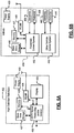
- Communication system 50 includes a receiver module 52 that employs a recursive channel estimation method (shown in FIG. 5 ).
- the recursive channel estimation method estimates conditions in a wireless communication channel 54.
- the recursive estimation method begins with a first long training sequence that is sent by a transmitter module 56.
- the recursive estimation method ends by generating a channel estimation matrix H when the last long training sequence has been received. Since the recursive estimation method develops a basis for generating matrix H while the long training sequences are being received, instead of starting after the long training sequences have been received, the recursive estimation method can generate matrix H faster than previously known methods.
- the matrix H can then be used to perform channel equalization in receiver module 52 to compensate for the effects of communication channel 54.
- a baseband module 58 generates data messages based on m streams of incoming data.
- Baseband module 58 communicates the data messages (shown in FIG. 4 ) to an encoder module 60.
- the data messages include respective long training fields that are compliant with IEEE 802.11n.
- Encoder module 60 encodes the long training fields into n data streams based on the matrix P, which is shown in FIG. 1 .
- Encoder module 60 communicates the n data streams to n respective transmit channels 62-1, ..., 62-n, which are referred to collectively as transmit channels 62.
- Each transmit channel 62 includes a respective modulation module 64 that modulates its respective data stream, such as with quadrature-amplitude modulation (QAM), and communicates the modulated data stream to a respective inverse fast-Fourier transform (IFFT) module 66.
- IFFT modules 66 convert their respective data streams from a frequency domain signal to a time domain signal.
- IFFT modules 66 communicate the time domain signals to respective radio frequency (RF) transmitters that are represented by antennas 68.
- RF radio frequency
- the transmitted data streams propagate through communication channel 54.
- Communication channel 54 perturbs the transmitted data streams due to phenomena such as reflections, signal attenuation, and so forth.
- the perturbations can be represented by matrix H.
- Receiver module 52 includes n RF receivers that are represented by antennas 70-1, ..., 70-n.
- the RF receivers receive the transmitted data streams and communicate the perturbed time domain signals to a channel estimator module 72.
- Channel estimator module 72 estimates matrix H based on matrix P and the long training fields that are included in the received data streams.
- channel estimator module 72 includes a processor 73 and associated memory 75 for storing and/or executing the recursive channel estimation methods that are described below.
- Channel estimator module 72 communicates the n received data streams to n respective fast-Fourier transform (FFT) modules 74 and adjusts gains of an equalizer module 76.
- FFT modules 74 convert the time-domain data streams to frequency-domain data streams and communicate them to equalizer module 76.
- Equalizer module 76 compensates the respective data streams based on the gains and communicates the compensated gains to a Viterbi decoder module 78.
- Viterbi decoder module 78 decodes the n data streams to generate received data streams y m .
- Transceiver 80 that includes transmitter module 56 and receiver module 52.
- Transceiver 80 can communicate with other transceivers 80 via antennas 82-1, ..., 82-n.
- An antennas switch module 84 selectively connects antennas 82 to transmitter module 56 or receiver module 52 based on whether transceiver 80 is transmitting or receiving.
- Data message 90 includes data 92 and a preamble 94 that contains a plurality of training fields. Preamble 94 is divided into a first portion 96 and a second portion 98.
- First portion 96 may be used by legacy systems, e.g. non-MIMO, IEEE 802.11 communication systems.
- Second portion 98 includes a signal filed field 100, a short training field 102, and x long training fields (LTFs) 104-1, ..., 104-x, where x is an integer.
- Each LTF 104 includes k training symbols 106 or tones.
- Short training field 102 is generally used by receiver module 52 to establish symbol timing of data message 90.
- Channel estimator module 72 uses LTFs 104 and their k respective training symbols 106 to estimate matrix H based on methods that are described below.
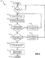
- Method 120 can be executed by channel estimator module 72.
- method 120 can be implemented as a computer program or firmware that is stored in memory 75 and executed by processor 73.
- decision block 124 control determines whether an LTF 104 is being received. If not then control returns to block 122. If an LTF 104 is being received then control branches from decision block 124 to block 126.
- block 126 control receives a training symbol 106 that is associated with the current LTF 104. Control then proceeds to block 128 and updates a matrix H est , which is described below in more detail, based on the current training symbol 106. Control then proceeds to decision block 130 and determines whether the current training symbol 106 was the last training symbol 106 of the present LTF 104. If not then control branches to block 132 and waits for the next training symbol 106 of the current LTF 104.
- control returns to block 126 and repeats the aforementioned steps for the new training symbol 106.
- control branches to decision block 134.
- control determines whether the current LTF 104 was the last LTF 104 (i.e. LTF 104-x) of the current group of LTFs 104. If not then control branches to block 136 and waits for the next LTF 104 to begin before returning to block 126. On the other hand, if the current LTF 104 was the last LTF 104-x then control branches from decision block 134 to block 138. In block 138 control generates matrix H based on matrix H est and matrix P. Control then proceeds to block 140 and adjusts the gains of equalizer module 76 based on matrix H. Control then returns to other processes via termination block 142.
- LTF 104-x the last LTF 104
- channel estimator module 72 executes method 120 it performs distributed QR across LTFs 104. That is, QR ( H est ) . Computational density therefore increases as O(n 2 ) and the processing latency of associated hardware and/or processor 73 would increase by about O(n 2 ). This represents an improvement, e.g. reduced need for processing power, over the prior art.
- Example estimations of matrix H est will now be provided for various MIMO dimensions of communications system 50.
- the 3x3 MIMO case employs a non-square matrix P.
- a distributed solution may also be employed by working directly with H est 3 x 4 without forming H.
- Q* H est 3 x 4 ⁇ R Q*h 4 ⁇
- QR H est 3 x 3 .
- Channel estimator module can store v in memory 75.
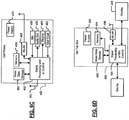
- the receiver module can be implemented in a high definition television (HDTV) 420.
- the receiver module may implement and/or be implemented in a WLAN interface 429.
- the HDTV 420 receives HDTV input signals in either a wired or wireless format and generates HDTV output signals for a display 426.
- signal processing circuit and/or control circuit 422 and/or other circuits (not shown) of the HDTV 420 may process data, perform coding and/or encryption, perform calculations, format data and/or perform any other type of HDTV processing that may be required.
- the HDTV 420 may communicate with mass data storage 427 that stores data in a nonvolatile manner such as optical and/or magnetic storage devices.
- Mass data storage 427 may include at least one hard disk drive (HDD) and/or at least one digital versatile disk (DVD) drive.
- the HDD may be a mini HDD that includes one or more platters having a diameter that is smaller than approximately 1.8".
- the HDTV 420 may be connected to memory 428 such as RAM, ROM, low latency nonvolatile memory such as flash memory and/or other suitable electronic data storage.
- the HDTV 420 also may support connections with a WLAN via WLAN network interface 429.
- the HDTV 420 also includes a power supply 423.
- the receiver module may implement and/or be implemented in a WLAN interface 448 of a vehicle 430.
- WLAN interface 448 communicates with a powertrain control system 432 that receives inputs from one or more sensors.
- sensors includes temperature sensors, pressure sensors, rotational sensors, airflow sensors and/or any other suitable sensors and/or that generates one or more output control signals such as engine operating parameters, transmission operating parameters, and/or other control signals.
- the receiver module may also be implemented in other control systems 440 of the vehicle 430.
- the control system 440 may likewise receive signals from input sensors 442 and/or output control signals to one or more output devices 444.
- the control system 440 may be part of an anti-lock braking system (ABS), a navigation system, a telematics system, a vehicle telematics system, a lane departure system, an adaptive cruise control system, a vehicle entertainment system such as a stereo, DVD, compact disc and the like. Still other implementations are contemplated.
- the powertrain control system 432 may communicate with mass data storage 446 that stores data in a nonvolatile manner.
- Mass data storage 446 may include at least one HDD and/or at least one DVD drive.
- the HDD may be a mini HDD that includes one or more platters having a diameter that is smaller than approximately 1.8".
- the powertrain control system 432 may be connected to memory 447 such as RAM, ROM, low latency nonvolatile memory such as flash memory and/or other suitable electronic data storage.
- the powertrain control system 432 also may support connections with a WLAN via a WLAN network interface 448.
- the control system 440 may also include mass data storage, memory and/or a WLAN interface (all not shown).
- Vehicle 430 may also include a power supply 433.
- the receiver module can be implemented in a cellular phone 450 that may include a cellular antenna 451.
- the receiver module may implement and/or be implemented in a WLAN interface 468.
- the cellular phone 450 includes a microphone 456, an audio output 458 such as a speaker and/or audio output jack, a display 460 and/or an input device 462 such as a keypad, pointing device, voice actuation and/or other input device.
- the signal processing and/or control circuits 452 and/or other circuits (not shown) in the cellular phone 450 may process data, perform coding and/or encryption, perform calculations, format data and/or perform other cellular phone functions.
- the cellular phone 450 may communicate with mass data storage 464 that stores data in a nonvolatile manner.
- Mass data storage 450 may include at least one HDD and/or at least one DVD drive.
- the HDD may be a mini HDD that includes one or more platters having a diameter that is smaller than approximately 1.8".
- the cellular phone 450 may be connected to memory 466 such as RAM, ROM, low latency nonvolatile memory such as flash memory and/or other suitable electronic data storage.
- the cellular phone 450 also may support connections with a WLAN via the WLAN network interface 468.
- the cellular phone 450 may also include a power supply 453.
- the receiver module can be implemented in a set top box 480.
- the receiver module may implement and/or be implemented in a WLAN interface 496.
- the set top box 480 receives signals from a source such as a broadband source and outputs standard and/or high definition audio/video signals suitable for a display 488 such as a television and/or monitor and/or other video and/or audio output devices.
- the signal processing and/or control circuits 484 and/or other circuits (not shown) of the set top box 480 may process data, perform coding and/or encryption, perform calculations, format data and/or perform any other set top box function.
- the set top box 480 may communicate with mass data storage 490 that stores data in a nonvolatile manner.
- Mass data storage 490 may include at least one HDD and/or at least one DVD drive.
- the HDD may be a mini HDD that includes one or more platters having a diameter that is smaller than approximately 1.8".
- the set top box 480 may be connected to memory 494 such as RAM, ROM, low latency nonvolatile memory such as flash memory and/or other suitable electronic data storage.
- the set top box 480 also may support connections with a WLAN via the WLAN network interface 496.
- the set top box 480 may include a power supply 483.
- the receiver module can be implemented in a media player 500.
- the receiver module may implement and/or be implemented in a WLAN interface 516.
- the media player 500 includes a display 507 and/or a user input 508 such as a keypad, touchpad and the like.
- the media player 500 may employ a graphical user interface (GUI) that typically employs menus, drop down menus, icons and/or a point-and-click interface via the display 507 and/or user input 508.
- GUI graphical user interface
- the media player 500 further includes an audio output 509 such as a speaker and/or audio output jack.
- the signal processing and/or control circuits 504 and/or other circuits (not shown) of the media player 500 may process data, perform coding and/or encryption, perform calculations, format data and/or perform any other media player function.
- the media player 500 may communicate with mass data storage 510 that stores data such as compressed audio and/or video content in a nonvolatile manner.
- the compressed audio files include files that are compliant with MP3 format or other suitable compressed audio and/or video formats.
- Mass data storage 510 may include at least one HDD and/or at least one DVD drive.
- the HDD may be a mini HDD that includes one or more platters having a diameter that is smaller than approximately 1.8".
- the media player 500 may be connected to memory 514 such as RAM, ROM, low latency nonvolatile memory such as flash memory and/or other suitable electronic data storage.
- the media player 500 also may support connections with a WLAN via the WLAN network interface 516.
- the media player 500 may also include a power supply 513. Still other implementations in addition to those described above are contemplated.
Claims (11)
- Empfängermodul (52) in einem MIMO (Multiple-Input-Multiple-Output)-Kommunikationssystem, umfassend
einen Eingang, der ausgebildet ist zum Empfangen einer Datennachricht (90) von einem drahtlosen Kommunikationskanal, wobei die Datennachricht eine Vielzahl von Trainingsfeldern (104) und Daten (92) aufweist, wobei die Vielzahl von Trainingsfeldern basierend auf Trainingssymbolen (20) und einer Lenkungsmatrix P vor dem Senden an das Empfängermodul erzeugt wurden, wobei die Lenkungsmatrix eine Anzahl von Reihen in Entsprechung zu der Anzahl von Sendeantennen (26) und eine Anzahl von Spalten in Entsprechung zu der Anzahl von Trainingsfeldern aufweist und eine Orthogonalität der Trainingssymbole sicherstellt, wenn diese von den Sendeantennen gesendet werden,
ein Kanalschätzungsmodul (72), das ausgebildet ist zum:rekursiven Schätzen einer Matrix Hest basierend auf einer Vielzahl von Trainingsfeldern, wobei jede Wiederholung der rekursiven Schätzung der Matrix Hest durchgeführt wird, nachdem ein entsprechendes aus der Vielzahl von Trainingsfeldern empfangen wurde, undrekursives Berechnen von Ausgleichsparametern basierend auf der Vielzahl von Trainingsfeldern, der Lenkungsmatrix P und einer QR-Dekomposition der Matrix Hest, wobei die rekursive Berechnung durchgeführt wird, wenn die Vielzahl von Trainingsfeldern empfangen werden, wobei die Ausgleichsparameter einen ersten Satz von Parametern basierend auf einer ersten Matrix, einen zweiten Satz von Parametern basierend auf einer zweiten Matrix und einen Vektorein Ausgleichsmodul (76), das ausgebildet ist zum Anwenden von Koeffizienten auf die Daten basierend auf den Ausgleichsparametern, wobei, nachdem die rekursive Berechnung der Ausgleichsparameter abgeschlossen ist, das Ausgleichsmodul: den ersten Satz von Parametern auf einen Vektor der Daten der Datennachricht anwendet, um ein erstes Zwischenergebnis zu erzeugen,den zweiten Satz von Parametern des ersten Zwischenergebnisses anwendet, um ein zweites Zwischenergebnis zu erzeugen,die Lenkungsmatrix auf das zweite Zwischenergebnis anwendet, um ein drittes Zwischenergebnis zu erzeugen, undWll auf das dritte Zwischenergebnis anwendet, um Benutzerdaten wiederherzustellen.
 - Empfängermodul nach Anspruch 1, wobei das Kanalschätzungsmodul die rekursive Berechnung beginnt, wenn es ein erstes aus der Vielzahl von Trainingsfeldern empfängt, und die rekursive Berechnung abschließt, wenn es ein letztes aus der Vielzahl von Trainingsfeldern empfängt.
- Empfängermodul nach Anspruch 1, das weiterhin eine Vielzahl von FET-Modulen (74) umfasst, die ausgebildet sind zum Wandeln der Daten von Zeitdomänensignalen zu Frequenzdomänensignalen.
- Empfängermodul nach Anspruch 3, wobei die entsprechenden Ausgänge der Vielzahl von FFT-Modulen mit entsprechenden Eingängen des Ausgleichsmoduls kommunizieren.
- Empfängermodul nach Anspruch 4, das weiterhin ein Viterbi-Deocodiermodul (78) umfasst, das ausgebildet ist zum Erzeugen von Datensymbolen basierend auf den Frequenzdomänensignalen, die von einem Ausgang des Ausgleichsmoduls kommuniziert werden.
- Empfängermodul nach Anspruch 1, wobei die Vielzahl von Trainingsfeldern mit IEEE 802.11n kompatibel sind.
- Sendeempfängermodul (80), das das Empfängermodul von Anspruch 1 und weiterhin ein Sendermodul umfasst.
- Sendeempfängermodul nach Anspruch 7, wobei das Sendermodul Trainingssymbole für das Einfügen in die Vielzahl von Trainingsfeldern erzeugt und ein Multiplikationsmodul (22) enthält, das ausgebildet ist zum Multiplizieren der Trainingssymbole mit der Lenkungsmatrix P.
- Sendeempfängermodul nach Anspruch 8, wobei die Lenkungsmatrix P eine Bedingungszahl gleich 1 aufweist.
- Sendeempfängermodul nach Anspruch 7, das weiterhin umfasst:N Empfangsantennen, die ausgebildet sind zum Empfangen der Datennachricht, wobei N eine Ganzzahl größer oder gleich 2 ist, undN Sendeantennen, die ausgebildet sind zum Senden der Datennachricht über N Ströme.
- Empfängermodul nach Anspruch 1, wobei die erste Matrix auf einer konjugierten Transponierten einer orthogonalen Matrix der QR-Dekomposition basiert und wobei die zweite Matrix auf einer Umkehrung einer oberen dreieckigen Matrix der QR-Dekomposition basiert.
Applications Claiming Priority (3)
| Application Number | Priority Date | Filing Date | Title |
|---|---|---|---|
| US75945306P | 2006-01-17 | 2006-01-17 | |
| US11/521,182 US7813421B2 (en) | 2006-01-17 | 2006-09-14 | Order recursive computation for a MIMO equalizer |
| PCT/US2007/001233 WO2007084562A1 (en) | 2006-01-17 | 2007-01-17 | Recursive computation of a channel matrix for a mimo equalizer |
Publications (2)
| Publication Number | Publication Date |
|---|---|
| EP1974512A1 EP1974512A1 (de) | 2008-10-01 |
| EP1974512B1 true EP1974512B1 (de) | 2018-08-22 |
Family
ID=38116161
Family Applications (1)
| Application Number | Title | Priority Date | Filing Date |
|---|---|---|---|
| EP07716730.2A Active EP1974512B1 (de) | 2006-01-17 | 2007-01-17 | Rekursive berechnung einer kanalmatrix für einen mimo-entzerrer |
Country Status (6)
| Country | Link |
|---|---|
| US (4) | US7813421B2 (de) |
| EP (1) | EP1974512B1 (de) |
| JP (1) | JP5160449B2 (de) |
| KR (1) | KR101373788B1 (de) |
| CN (1) | CN101371537B (de) |
| WO (1) | WO2007084562A1 (de) |
Families Citing this family (20)
| Publication number | Priority date | Publication date | Assignee | Title |
|---|---|---|---|---|
| US8494084B1 (en) | 2006-05-02 | 2013-07-23 | Marvell International Ltd. | Reuse of a matrix equalizer for the purpose of transmit beamforming in a wireless MIMO communication system |
| US8223872B1 (en) | 2007-04-04 | 2012-07-17 | Marvell International Ltd. | Reuse of a matrix equalizer for the purpose of transmit beamforming in a wireless MIMO communication system |
| US8199841B1 (en) | 2007-04-26 | 2012-06-12 | Marvell International Ltd. | Channel tracking in a wireless multiple-input multiple-output (MIMO) communication system |
| US8077805B1 (en) | 2007-04-27 | 2011-12-13 | Marvell International Ltd. | MIMO equalizer method and apparatus |
| US8155233B1 (en) | 2007-09-11 | 2012-04-10 | Marvell International Ltd. | MIMO decoding in the presence of various interfering sources |
| US8229017B1 (en) | 2007-12-13 | 2012-07-24 | Marvell International Ltd. | Transmit beamforming utilizing channel estimation matrix decomposition feedback in a wireless MIMO communication system |
| CN101247373B (zh) * | 2008-03-20 | 2010-07-28 | 上海交通大学 | 基于免疫网络的正交频分复用系统的动态信道均衡方法 |
| KR101531740B1 (ko) * | 2008-07-29 | 2015-06-25 | 파나소닉 인텔렉츄얼 프로퍼티 코포레이션 오브 아메리카 | 송신 장치 및 송신 방법 |
| US8411806B1 (en) | 2008-09-03 | 2013-04-02 | Marvell International Ltd. | Method and apparatus for receiving signals in a MIMO system with multiple channel encoders |
| US8750215B2 (en) * | 2012-03-06 | 2014-06-10 | Intel Corporation | Method and apparatus for a 1 MHz long training field design |
| US20140160957A1 (en) * | 2012-12-11 | 2014-06-12 | Broadcom Corporation | Channel state information calibration |
| US9197461B1 (en) | 2013-03-12 | 2015-11-24 | Marvell International Ltd. | Method and apparatus for memory efficient architecture of successive interference cancellation for MIMO systems |
| KR101550110B1 (ko) | 2013-12-30 | 2015-09-04 | 알까뗄 루슨트 | Mimo 시스템의 추정을 위한 광의-선형 프레임워크 |
| US9660736B2 (en) * | 2014-11-19 | 2017-05-23 | Intel Corporation | Systems, methods, and devices for interference mitigation in wireless networks |
| JP6472259B2 (ja) | 2015-02-10 | 2019-02-20 | キヤノン株式会社 | 通信装置、通信装置の制御方法、プログラム |
| US9722730B1 (en) | 2015-02-12 | 2017-08-01 | Marvell International Ltd. | Multi-stream demodulation schemes with progressive optimization |
| JP6699738B2 (ja) | 2016-01-29 | 2020-05-27 | 日本電気株式会社 | 情報処理装置、情報処理方法、及び、コンピュータプログラム |
| US10014026B1 (en) * | 2017-06-20 | 2018-07-03 | Seagate Technology Llc | Head delay calibration and tracking in MSMR systems |
| US11018729B2 (en) | 2019-05-21 | 2021-05-25 | Nxp Usa, Inc. | Structured-pipelined CORDIC for matrix equalization |
| CN111246485B (zh) * | 2020-02-27 | 2022-09-20 | 华南理工大学 | 一种高密度车载通信环境下的车联网资源分配方法 |
Family Cites Families (18)
| Publication number | Priority date | Publication date | Assignee | Title |
|---|---|---|---|---|
| AT407933B (de) * | 1998-06-09 | 2001-07-25 | Juha Dipl Ing Laurila | Verfahren zur trennung und zur detektion von gleichkanal-signalen |
| US20020027985A1 (en) * | 2000-06-12 | 2002-03-07 | Farrokh Rashid-Farrokhi | Parallel processing for multiple-input, multiple-output, DSL systems |
| US7050513B1 (en) * | 2001-02-20 | 2006-05-23 | Comsys Communications & Signal Processing Ltd. | Block based channel tracking using weighted recursive least squares |
| GB2392065B (en) * | 2002-08-15 | 2004-12-29 | Toshiba Res Europ Ltd | Signal decoding methods and apparatus |
| US7239672B2 (en) * | 2002-09-05 | 2007-07-03 | Silicon Integrated Systems Corp. | Channel estimator for WLAN |
| JP4298320B2 (ja) * | 2002-11-08 | 2009-07-15 | 富士通株式会社 | Ofdm伝送方式における受信装置 |
| CN1200521C (zh) * | 2003-06-18 | 2005-05-04 | 清华大学 | 用于频域均衡的导频插入与信道参数估计的方法 |
| US20050141657A1 (en) * | 2003-12-30 | 2005-06-30 | Maltsev Alexander A. | Adaptive channel equalizer for wireless system |
| GB2411328B (en) * | 2004-02-23 | 2007-05-16 | Toshiba Res Europ Ltd | Adaptive MIMO systems |
| US7346129B2 (en) * | 2004-02-25 | 2008-03-18 | Broadcom Corporation | Payload based channel estimation of a wireless channel |
| US20050201454A1 (en) * | 2004-03-12 | 2005-09-15 | Intel Corporation | System and method for automatically calibrating two-tap and multi-tap equalization for a communications link |
| JP4543737B2 (ja) * | 2004-05-10 | 2010-09-15 | ソニー株式会社 | 無線通信システム、無線通信装置及び無線通信方法、並びにコンピュータ・プログラム |
| US7110463B2 (en) * | 2004-06-30 | 2006-09-19 | Qualcomm, Incorporated | Efficient computation of spatial filter matrices for steering transmit diversity in a MIMO communication system |
| US7616955B2 (en) * | 2004-11-12 | 2009-11-10 | Broadcom Corporation | Method and system for bits and coding assignment utilizing Eigen beamforming with fixed rates for closed loop WLAN |
| CA2587770A1 (en) * | 2004-11-05 | 2006-05-18 | University Of Florida Research Foundation, Inc. | Uniform channel decomposition for mimo communications |
| GB2423437B (en) * | 2005-02-16 | 2007-06-13 | Toshiba Res Europ Ltd | Communications system, method and device |
| US7978759B1 (en) * | 2005-03-24 | 2011-07-12 | Marvell International Ltd. | Scalable equalizer for multiple-in-multiple-out (MIMO) wireless transmission |
| US20070127608A1 (en) * | 2005-12-06 | 2007-06-07 | Jacob Scheim | Blind interference mitigation in a digital receiver |
-
2006
- 2006-09-14 US US11/521,182 patent/US7813421B2/en active Active
-
2007
- 2007-01-17 JP JP2008550466A patent/JP5160449B2/ja active Active
- 2007-01-17 KR KR1020087020091A patent/KR101373788B1/ko active IP Right Grant
- 2007-01-17 CN CN2007800025191A patent/CN101371537B/zh active Active
- 2007-01-17 EP EP07716730.2A patent/EP1974512B1/de active Active
- 2007-01-17 WO PCT/US2007/001233 patent/WO2007084562A1/en active Application Filing
-
2010
- 2010-10-12 US US12/902,394 patent/US8340169B1/en active Active
-
2012
- 2012-12-21 US US13/725,167 patent/US8699556B1/en active Active
-
2014
- 2014-04-15 US US14/252,860 patent/US9001873B2/en active Active
Non-Patent Citations (1)
| Title |
|---|
| None * |
Also Published As
| Publication number | Publication date |
|---|---|
| KR101373788B1 (ko) | 2014-03-13 |
| WO2007084562A1 (en) | 2007-07-26 |
| CN101371537B (zh) | 2012-07-18 |
| JP5160449B2 (ja) | 2013-03-13 |
| US8699556B1 (en) | 2014-04-15 |
| JP2009524291A (ja) | 2009-06-25 |
| CN101371537A (zh) | 2009-02-18 |
| KR20080098495A (ko) | 2008-11-10 |
| US20070165737A1 (en) | 2007-07-19 |
| US7813421B2 (en) | 2010-10-12 |
| EP1974512A1 (de) | 2008-10-01 |
| US9001873B2 (en) | 2015-04-07 |
| US20140226703A1 (en) | 2014-08-14 |
| US8340169B1 (en) | 2012-12-25 |
Similar Documents
| Publication | Publication Date | Title |
|---|---|---|
| EP1974512B1 (de) | Rekursive berechnung einer kanalmatrix für einen mimo-entzerrer | |
| US9166836B1 (en) | Channel tracking in a wireless multiple-input multiple-output (MIMO) communication system | |
| JP6219334B2 (ja) | Mimo通信システムにおいて送信ダイバシティをステアリングするための空間フィルターマトリックスの効率的な計算 | |
| US8223872B1 (en) | Reuse of a matrix equalizer for the purpose of transmit beamforming in a wireless MIMO communication system | |
| EP2485409B1 (de) | Antennenauswahl und -training mithilfe einer räumlichen verbreitungsmatrix zur verwendung in einem mimo drahtlosen mimo-kommunikationssystem | |
| US7561632B1 (en) | Beamforming techniques for MIMO communication systems | |
| CN1875562B (zh) | 宽带miso和mimo系统的频率无关空间处理 | |
| US9215121B1 (en) | Method and apparatus for implementing transmit diversity in OFDM systems | |
| US8095097B1 (en) | Increasing the robustness of channel estimates derived through sounding for WLAN | |
| EP1869854A2 (de) | Verfahren und vorrichtung zur zerlegung einer kanalmatrix in einzelwerte | |
| Gao et al. | Blind channel estimation for MIMO OFDM systems via nonredundant linear precoding | |
| US8204103B1 (en) | Scalable equalizer for multiple-in-multiple-out (MIMO) wireless transmission | |
| JP2007513554A (ja) | 線形プリコーディングされた信号のマルチアンテナ伝送方法、対応するデバイス、信号、および受信方法 | |
| US20080181335A1 (en) | Wireless communication apparatus | |
| Foster et al. | Polynomial matrix QR decomposition for the decoding of frequency selective multiple-input multiple-output communication channels | |
| US8494099B2 (en) | Signal processing using modified blockwise analytic matrix inversion | |
| US8077805B1 (en) | MIMO equalizer method and apparatus | |
| KR100801669B1 (ko) | 적응형 주파수 영역 등화기 및 주파수 영역 등화 방법 | |
| Priyadarsini | Performance analysis of subspace methods used in blind channel identification | |
| Chong et al. | A performance analysis of optimal detection ordering zero-forcing VBLAST with maximum a posteriori probability orthogonal frequency division multiplexing | |
| TW201347446A (zh) | 頻稻矩陣奇異值分解方法及裝置 |
Legal Events
| Date | Code | Title | Description |
|---|---|---|---|
| PUAI | Public reference made under article 153(3) epc to a published international application that has entered the european phase |
Free format text: ORIGINAL CODE: 0009012 |
|
| 17P | Request for examination filed |
Effective date: 20080714 |
|
| AK | Designated contracting states |
Kind code of ref document: A1 Designated state(s): AT BE BG CH CY CZ DE DK EE ES FI FR GB GR HU IE IS IT LI LT LU LV MC NL PL PT RO SE SI SK TR |
|
| 17Q | First examination report despatched |
Effective date: 20090219 |
|
| DAX | Request for extension of the european patent (deleted) | ||
| STAA | Information on the status of an ep patent application or granted ep patent |
Free format text: STATUS: EXAMINATION IS IN PROGRESS |
|
| GRAP | Despatch of communication of intention to grant a patent |
Free format text: ORIGINAL CODE: EPIDOSNIGR1 |
|
| STAA | Information on the status of an ep patent application or granted ep patent |
Free format text: STATUS: GRANT OF PATENT IS INTENDED |
|
| INTG | Intention to grant announced |
Effective date: 20180323 |
|
| GRAS | Grant fee paid |
Free format text: ORIGINAL CODE: EPIDOSNIGR3 |
|
| GRAA | (expected) grant |
Free format text: ORIGINAL CODE: 0009210 |
|
| STAA | Information on the status of an ep patent application or granted ep patent |
Free format text: STATUS: THE PATENT HAS BEEN GRANTED |
|
| AK | Designated contracting states |
Kind code of ref document: B1 Designated state(s): AT BE BG CH CY CZ DE DK EE ES FI FR GB GR HU IE IS IT LI LT LU LV MC NL PL PT RO SE SI SK TR |
|
| REG | Reference to a national code |
Ref country code: GB Ref legal event code: FG4D |
|
| REG | Reference to a national code |
Ref country code: CH Ref legal event code: EP |
|
| REG | Reference to a national code |
Ref country code: AT Ref legal event code: REF Ref document number: 1033770 Country of ref document: AT Kind code of ref document: T Effective date: 20180915 |
|
| REG | Reference to a national code |
Ref country code: IE Ref legal event code: FG4D |
|
| REG | Reference to a national code |
Ref country code: DE Ref legal event code: R096 Ref document number: 602007055836 Country of ref document: DE |
|
| REG | Reference to a national code |
Ref country code: NL Ref legal event code: MP Effective date: 20180822 |
|
| REG | Reference to a national code |
Ref country code: LT Ref legal event code: MG4D |
|
| PG25 | Lapsed in a contracting state [announced via postgrant information from national office to epo] |
Ref country code: SE Free format text: LAPSE BECAUSE OF FAILURE TO SUBMIT A TRANSLATION OF THE DESCRIPTION OR TO PAY THE FEE WITHIN THE PRESCRIBED TIME-LIMIT Effective date: 20180822 Ref country code: BG Free format text: LAPSE BECAUSE OF FAILURE TO SUBMIT A TRANSLATION OF THE DESCRIPTION OR TO PAY THE FEE WITHIN THE PRESCRIBED TIME-LIMIT Effective date: 20181122 Ref country code: GR Free format text: LAPSE BECAUSE OF FAILURE TO SUBMIT A TRANSLATION OF THE DESCRIPTION OR TO PAY THE FEE WITHIN THE PRESCRIBED TIME-LIMIT Effective date: 20181123 Ref country code: IS Free format text: LAPSE BECAUSE OF FAILURE TO SUBMIT A TRANSLATION OF THE DESCRIPTION OR TO PAY THE FEE WITHIN THE PRESCRIBED TIME-LIMIT Effective date: 20181222 Ref country code: FI Free format text: LAPSE BECAUSE OF FAILURE TO SUBMIT A TRANSLATION OF THE DESCRIPTION OR TO PAY THE FEE WITHIN THE PRESCRIBED TIME-LIMIT Effective date: 20180822 Ref country code: LT Free format text: LAPSE BECAUSE OF FAILURE TO SUBMIT A TRANSLATION OF THE DESCRIPTION OR TO PAY THE FEE WITHIN THE PRESCRIBED TIME-LIMIT Effective date: 20180822 Ref country code: NL Free format text: LAPSE BECAUSE OF FAILURE TO SUBMIT A TRANSLATION OF THE DESCRIPTION OR TO PAY THE FEE WITHIN THE PRESCRIBED TIME-LIMIT Effective date: 20180822 |
|
| REG | Reference to a national code |
Ref country code: AT Ref legal event code: MK05 Ref document number: 1033770 Country of ref document: AT Kind code of ref document: T Effective date: 20180822 |
|
| PG25 | Lapsed in a contracting state [announced via postgrant information from national office to epo] |
Ref country code: LV Free format text: LAPSE BECAUSE OF FAILURE TO SUBMIT A TRANSLATION OF THE DESCRIPTION OR TO PAY THE FEE WITHIN THE PRESCRIBED TIME-LIMIT Effective date: 20180822 Ref country code: ES Free format text: LAPSE BECAUSE OF FAILURE TO SUBMIT A TRANSLATION OF THE DESCRIPTION OR TO PAY THE FEE WITHIN THE PRESCRIBED TIME-LIMIT Effective date: 20180822 |
|
| PG25 | Lapsed in a contracting state [announced via postgrant information from national office to epo] |
Ref country code: RO Free format text: LAPSE BECAUSE OF FAILURE TO SUBMIT A TRANSLATION OF THE DESCRIPTION OR TO PAY THE FEE WITHIN THE PRESCRIBED TIME-LIMIT Effective date: 20180822 Ref country code: IT Free format text: LAPSE BECAUSE OF FAILURE TO SUBMIT A TRANSLATION OF THE DESCRIPTION OR TO PAY THE FEE WITHIN THE PRESCRIBED TIME-LIMIT Effective date: 20180822 Ref country code: EE Free format text: LAPSE BECAUSE OF FAILURE TO SUBMIT A TRANSLATION OF THE DESCRIPTION OR TO PAY THE FEE WITHIN THE PRESCRIBED TIME-LIMIT Effective date: 20180822 Ref country code: CZ Free format text: LAPSE BECAUSE OF FAILURE TO SUBMIT A TRANSLATION OF THE DESCRIPTION OR TO PAY THE FEE WITHIN THE PRESCRIBED TIME-LIMIT Effective date: 20180822 Ref country code: PL Free format text: LAPSE BECAUSE OF FAILURE TO SUBMIT A TRANSLATION OF THE DESCRIPTION OR TO PAY THE FEE WITHIN THE PRESCRIBED TIME-LIMIT Effective date: 20180822 Ref country code: AT Free format text: LAPSE BECAUSE OF FAILURE TO SUBMIT A TRANSLATION OF THE DESCRIPTION OR TO PAY THE FEE WITHIN THE PRESCRIBED TIME-LIMIT Effective date: 20180822 |
|
| REG | Reference to a national code |
Ref country code: DE Ref legal event code: R097 Ref document number: 602007055836 Country of ref document: DE |
|
| PG25 | Lapsed in a contracting state [announced via postgrant information from national office to epo] |
Ref country code: SK Free format text: LAPSE BECAUSE OF FAILURE TO SUBMIT A TRANSLATION OF THE DESCRIPTION OR TO PAY THE FEE WITHIN THE PRESCRIBED TIME-LIMIT Effective date: 20180822 Ref country code: DK Free format text: LAPSE BECAUSE OF FAILURE TO SUBMIT A TRANSLATION OF THE DESCRIPTION OR TO PAY THE FEE WITHIN THE PRESCRIBED TIME-LIMIT Effective date: 20180822 |
|
| PLBE | No opposition filed within time limit |
Free format text: ORIGINAL CODE: 0009261 |
|
| STAA | Information on the status of an ep patent application or granted ep patent |
Free format text: STATUS: NO OPPOSITION FILED WITHIN TIME LIMIT |
|
| 26N | No opposition filed |
Effective date: 20190523 |
|
| PG25 | Lapsed in a contracting state [announced via postgrant information from national office to epo] |
Ref country code: MC Free format text: LAPSE BECAUSE OF FAILURE TO SUBMIT A TRANSLATION OF THE DESCRIPTION OR TO PAY THE FEE WITHIN THE PRESCRIBED TIME-LIMIT Effective date: 20180822 Ref country code: SI Free format text: LAPSE BECAUSE OF FAILURE TO SUBMIT A TRANSLATION OF THE DESCRIPTION OR TO PAY THE FEE WITHIN THE PRESCRIBED TIME-LIMIT Effective date: 20180822 |
|
| REG | Reference to a national code |
Ref country code: CH Ref legal event code: PL |
|
| PG25 | Lapsed in a contracting state [announced via postgrant information from national office to epo] |
Ref country code: LU Free format text: LAPSE BECAUSE OF NON-PAYMENT OF DUE FEES Effective date: 20190117 |
|
| REG | Reference to a national code |
Ref country code: BE Ref legal event code: MM Effective date: 20190131 |
|
| REG | Reference to a national code |
Ref country code: IE Ref legal event code: MM4A |
|
| PG25 | Lapsed in a contracting state [announced via postgrant information from national office to epo] |
Ref country code: BE Free format text: LAPSE BECAUSE OF NON-PAYMENT OF DUE FEES Effective date: 20190131 |
|
| PG25 | Lapsed in a contracting state [announced via postgrant information from national office to epo] |
Ref country code: LI Free format text: LAPSE BECAUSE OF NON-PAYMENT OF DUE FEES Effective date: 20190131 Ref country code: CH Free format text: LAPSE BECAUSE OF NON-PAYMENT OF DUE FEES Effective date: 20190131 |
|
| PG25 | Lapsed in a contracting state [announced via postgrant information from national office to epo] |
Ref country code: IE Free format text: LAPSE BECAUSE OF NON-PAYMENT OF DUE FEES Effective date: 20190117 |
|
| PG25 | Lapsed in a contracting state [announced via postgrant information from national office to epo] |
Ref country code: TR Free format text: LAPSE BECAUSE OF FAILURE TO SUBMIT A TRANSLATION OF THE DESCRIPTION OR TO PAY THE FEE WITHIN THE PRESCRIBED TIME-LIMIT Effective date: 20180822 |
|
| REG | Reference to a national code |
Ref country code: DE Ref legal event code: R082 Ref document number: 602007055836 Country of ref document: DE Representative=s name: GRUENECKER PATENT- UND RECHTSANWAELTE PARTG MB, DE Ref country code: DE Ref legal event code: R081 Ref document number: 602007055836 Country of ref document: DE Owner name: MARVELL ASIA PTE, LTD., SG Free format text: FORMER OWNER: MARVELL WORLD TRADE LTD., ST. MICHAEL, BB |
|
| PG25 | Lapsed in a contracting state [announced via postgrant information from national office to epo] |
Ref country code: PT Free format text: LAPSE BECAUSE OF FAILURE TO SUBMIT A TRANSLATION OF THE DESCRIPTION OR TO PAY THE FEE WITHIN THE PRESCRIBED TIME-LIMIT Effective date: 20181222 |
|
| REG | Reference to a national code |
Ref country code: GB Ref legal event code: 732E Free format text: REGISTERED BETWEEN 20200709 AND 20200715 |
|
| PG25 | Lapsed in a contracting state [announced via postgrant information from national office to epo] |
Ref country code: CY Free format text: LAPSE BECAUSE OF FAILURE TO SUBMIT A TRANSLATION OF THE DESCRIPTION OR TO PAY THE FEE WITHIN THE PRESCRIBED TIME-LIMIT Effective date: 20180822 |
|
| PG25 | Lapsed in a contracting state [announced via postgrant information from national office to epo] |
Ref country code: HU Free format text: LAPSE BECAUSE OF FAILURE TO SUBMIT A TRANSLATION OF THE DESCRIPTION OR TO PAY THE FEE WITHIN THE PRESCRIBED TIME-LIMIT; INVALID AB INITIO Effective date: 20070117 |
|
| PGFP | Annual fee paid to national office [announced via postgrant information from national office to epo] |
Ref country code: FR Payment date: 20230124 Year of fee payment: 17 |
|
| PGFP | Annual fee paid to national office [announced via postgrant information from national office to epo] |
Ref country code: GB Payment date: 20230124 Year of fee payment: 17 Ref country code: DE Payment date: 20230127 Year of fee payment: 17 |
|
| P01 | Opt-out of the competence of the unified patent court (upc) registered |
Effective date: 20230508 |