EP1974352B1 - Method for producing a space layer in between two disks with high uniformity - Google Patents
Method for producing a space layer in between two disks with high uniformity Download PDFInfo
- Publication number
- EP1974352B1 EP1974352B1 EP06817769A EP06817769A EP1974352B1 EP 1974352 B1 EP1974352 B1 EP 1974352B1 EP 06817769 A EP06817769 A EP 06817769A EP 06817769 A EP06817769 A EP 06817769A EP 1974352 B1 EP1974352 B1 EP 1974352B1
- Authority
- EP
- European Patent Office
- Prior art keywords
- substrates
- bonding
- substrate
- lacquer
- layer
- Prior art date
- Legal status (The legal status is an assumption and is not a legal conclusion. Google has not performed a legal analysis and makes no representation as to the accuracy of the status listed.)
- Not-in-force
Links
Images
Classifications
-
- B—PERFORMING OPERATIONS; TRANSPORTING
- B29—WORKING OF PLASTICS; WORKING OF SUBSTANCES IN A PLASTIC STATE IN GENERAL
- B29C—SHAPING OR JOINING OF PLASTICS; SHAPING OF MATERIAL IN A PLASTIC STATE, NOT OTHERWISE PROVIDED FOR; AFTER-TREATMENT OF THE SHAPED PRODUCTS, e.g. REPAIRING
- B29C65/00—Joining or sealing of preformed parts, e.g. welding of plastics materials; Apparatus therefor
- B29C65/48—Joining or sealing of preformed parts, e.g. welding of plastics materials; Apparatus therefor using adhesives, i.e. using supplementary joining material; solvent bonding
- B29C65/52—Joining or sealing of preformed parts, e.g. welding of plastics materials; Apparatus therefor using adhesives, i.e. using supplementary joining material; solvent bonding characterised by the way of applying the adhesive
- B29C65/521—Joining or sealing of preformed parts, e.g. welding of plastics materials; Apparatus therefor using adhesives, i.e. using supplementary joining material; solvent bonding characterised by the way of applying the adhesive by spin coating
-
- B—PERFORMING OPERATIONS; TRANSPORTING
- B29—WORKING OF PLASTICS; WORKING OF SUBSTANCES IN A PLASTIC STATE IN GENERAL
- B29C—SHAPING OR JOINING OF PLASTICS; SHAPING OF MATERIAL IN A PLASTIC STATE, NOT OTHERWISE PROVIDED FOR; AFTER-TREATMENT OF THE SHAPED PRODUCTS, e.g. REPAIRING
- B29C65/00—Joining or sealing of preformed parts, e.g. welding of plastics materials; Apparatus therefor
- B29C65/02—Joining or sealing of preformed parts, e.g. welding of plastics materials; Apparatus therefor by heating, with or without pressure
- B29C65/14—Joining or sealing of preformed parts, e.g. welding of plastics materials; Apparatus therefor by heating, with or without pressure using wave energy, i.e. electromagnetic radiation, or particle radiation
- B29C65/1403—Joining or sealing of preformed parts, e.g. welding of plastics materials; Apparatus therefor by heating, with or without pressure using wave energy, i.e. electromagnetic radiation, or particle radiation characterised by the type of electromagnetic or particle radiation
- B29C65/1406—Ultraviolet [UV] radiation
-
- B—PERFORMING OPERATIONS; TRANSPORTING
- B29—WORKING OF PLASTICS; WORKING OF SUBSTANCES IN A PLASTIC STATE IN GENERAL
- B29C—SHAPING OR JOINING OF PLASTICS; SHAPING OF MATERIAL IN A PLASTIC STATE, NOT OTHERWISE PROVIDED FOR; AFTER-TREATMENT OF THE SHAPED PRODUCTS, e.g. REPAIRING
- B29C65/00—Joining or sealing of preformed parts, e.g. welding of plastics materials; Apparatus therefor
- B29C65/48—Joining or sealing of preformed parts, e.g. welding of plastics materials; Apparatus therefor using adhesives, i.e. using supplementary joining material; solvent bonding
- B29C65/4805—Joining or sealing of preformed parts, e.g. welding of plastics materials; Apparatus therefor using adhesives, i.e. using supplementary joining material; solvent bonding characterised by the type of adhesives
- B29C65/483—Reactive adhesives, e.g. chemically curing adhesives
- B29C65/4845—Radiation curing adhesives, e.g. UV light curing adhesives
-
- B—PERFORMING OPERATIONS; TRANSPORTING
- B29—WORKING OF PLASTICS; WORKING OF SUBSTANCES IN A PLASTIC STATE IN GENERAL
- B29C—SHAPING OR JOINING OF PLASTICS; SHAPING OF MATERIAL IN A PLASTIC STATE, NOT OTHERWISE PROVIDED FOR; AFTER-TREATMENT OF THE SHAPED PRODUCTS, e.g. REPAIRING
- B29C65/00—Joining or sealing of preformed parts, e.g. welding of plastics materials; Apparatus therefor
- B29C65/76—Making non-permanent or releasable joints
-
- B—PERFORMING OPERATIONS; TRANSPORTING
- B29—WORKING OF PLASTICS; WORKING OF SUBSTANCES IN A PLASTIC STATE IN GENERAL
- B29C—SHAPING OR JOINING OF PLASTICS; SHAPING OF MATERIAL IN A PLASTIC STATE, NOT OTHERWISE PROVIDED FOR; AFTER-TREATMENT OF THE SHAPED PRODUCTS, e.g. REPAIRING
- B29C66/00—General aspects of processes or apparatus for joining preformed parts
- B29C66/001—Joining in special atmospheres
-
- B—PERFORMING OPERATIONS; TRANSPORTING
- B29—WORKING OF PLASTICS; WORKING OF SUBSTANCES IN A PLASTIC STATE IN GENERAL
- B29C—SHAPING OR JOINING OF PLASTICS; SHAPING OF MATERIAL IN A PLASTIC STATE, NOT OTHERWISE PROVIDED FOR; AFTER-TREATMENT OF THE SHAPED PRODUCTS, e.g. REPAIRING
- B29C66/00—General aspects of processes or apparatus for joining preformed parts
- B29C66/01—General aspects dealing with the joint area or with the area to be joined
- B29C66/05—Particular design of joint configurations
- B29C66/10—Particular design of joint configurations particular design of the joint cross-sections
- B29C66/11—Joint cross-sections comprising a single joint-segment, i.e. one of the parts to be joined comprising a single joint-segment in the joint cross-section
- B29C66/112—Single lapped joints
- B29C66/1122—Single lap to lap joints, i.e. overlap joints
-
- B—PERFORMING OPERATIONS; TRANSPORTING
- B29—WORKING OF PLASTICS; WORKING OF SUBSTANCES IN A PLASTIC STATE IN GENERAL
- B29C—SHAPING OR JOINING OF PLASTICS; SHAPING OF MATERIAL IN A PLASTIC STATE, NOT OTHERWISE PROVIDED FOR; AFTER-TREATMENT OF THE SHAPED PRODUCTS, e.g. REPAIRING
- B29C66/00—General aspects of processes or apparatus for joining preformed parts
- B29C66/40—General aspects of joining substantially flat articles, e.g. plates, sheets or web-like materials; Making flat seams in tubular or hollow articles; Joining single elements to substantially flat surfaces
- B29C66/41—Joining substantially flat articles ; Making flat seams in tubular or hollow articles
- B29C66/45—Joining of substantially the whole surface of the articles
- B29C66/452—Joining of substantially the whole surface of the articles the article having a disc form, e.g. making CDs or DVDs
-
- B—PERFORMING OPERATIONS; TRANSPORTING
- B29—WORKING OF PLASTICS; WORKING OF SUBSTANCES IN A PLASTIC STATE IN GENERAL
- B29C—SHAPING OR JOINING OF PLASTICS; SHAPING OF MATERIAL IN A PLASTIC STATE, NOT OTHERWISE PROVIDED FOR; AFTER-TREATMENT OF THE SHAPED PRODUCTS, e.g. REPAIRING
- B29C66/00—General aspects of processes or apparatus for joining preformed parts
- B29C66/80—General aspects of machine operations or constructions and parts thereof
- B29C66/82—Pressure application arrangements, e.g. transmission or actuating mechanisms for joining tools or clamps
- B29C66/826—Pressure application arrangements, e.g. transmission or actuating mechanisms for joining tools or clamps without using a separate pressure application tool, e.g. the own weight of the parts to be joined
- B29C66/8266—Pressure application arrangements, e.g. transmission or actuating mechanisms for joining tools or clamps without using a separate pressure application tool, e.g. the own weight of the parts to be joined using fluid pressure directly acting on the parts to be joined
- B29C66/82661—Pressure application arrangements, e.g. transmission or actuating mechanisms for joining tools or clamps without using a separate pressure application tool, e.g. the own weight of the parts to be joined using fluid pressure directly acting on the parts to be joined by means of vacuum
-
- B—PERFORMING OPERATIONS; TRANSPORTING
- B32—LAYERED PRODUCTS
- B32B—LAYERED PRODUCTS, i.e. PRODUCTS BUILT-UP OF STRATA OF FLAT OR NON-FLAT, e.g. CELLULAR OR HONEYCOMB, FORM
- B32B37/00—Methods or apparatus for laminating, e.g. by curing or by ultrasonic bonding
- B32B37/12—Methods or apparatus for laminating, e.g. by curing or by ultrasonic bonding characterised by using adhesives
-
- C—CHEMISTRY; METALLURGY
- C09—DYES; PAINTS; POLISHES; NATURAL RESINS; ADHESIVES; COMPOSITIONS NOT OTHERWISE PROVIDED FOR; APPLICATIONS OF MATERIALS NOT OTHERWISE PROVIDED FOR
- C09J—ADHESIVES; NON-MECHANICAL ASPECTS OF ADHESIVE PROCESSES IN GENERAL; ADHESIVE PROCESSES NOT PROVIDED FOR ELSEWHERE; USE OF MATERIALS AS ADHESIVES
- C09J5/00—Adhesive processes in general; Adhesive processes not provided for elsewhere, e.g. relating to primers
- C09J5/02—Adhesive processes in general; Adhesive processes not provided for elsewhere, e.g. relating to primers involving pretreatment of the surfaces to be joined
-
- G—PHYSICS
- G11—INFORMATION STORAGE
- G11B—INFORMATION STORAGE BASED ON RELATIVE MOVEMENT BETWEEN RECORD CARRIER AND TRANSDUCER
- G11B7/00—Recording or reproducing by optical means, e.g. recording using a thermal beam of optical radiation by modifying optical properties or the physical structure, reproducing using an optical beam at lower power by sensing optical properties; Record carriers therefor
- G11B7/24—Record carriers characterised by shape, structure or physical properties, or by the selection of the material
- G11B7/24018—Laminated discs
-
- G—PHYSICS
- G11—INFORMATION STORAGE
- G11B—INFORMATION STORAGE BASED ON RELATIVE MOVEMENT BETWEEN RECORD CARRIER AND TRANSDUCER
- G11B7/00—Recording or reproducing by optical means, e.g. recording using a thermal beam of optical radiation by modifying optical properties or the physical structure, reproducing using an optical beam at lower power by sensing optical properties; Record carriers therefor
- G11B7/24—Record carriers characterised by shape, structure or physical properties, or by the selection of the material
- G11B7/26—Apparatus or processes specially adapted for the manufacture of record carriers
-
- B—PERFORMING OPERATIONS; TRANSPORTING
- B29—WORKING OF PLASTICS; WORKING OF SUBSTANCES IN A PLASTIC STATE IN GENERAL
- B29C—SHAPING OR JOINING OF PLASTICS; SHAPING OF MATERIAL IN A PLASTIC STATE, NOT OTHERWISE PROVIDED FOR; AFTER-TREATMENT OF THE SHAPED PRODUCTS, e.g. REPAIRING
- B29C35/00—Heating, cooling or curing, e.g. crosslinking or vulcanising; Apparatus therefor
- B29C35/02—Heating or curing, e.g. crosslinking or vulcanizing during moulding, e.g. in a mould
- B29C35/08—Heating or curing, e.g. crosslinking or vulcanizing during moulding, e.g. in a mould by wave energy or particle radiation
- B29C35/0805—Heating or curing, e.g. crosslinking or vulcanizing during moulding, e.g. in a mould by wave energy or particle radiation using electromagnetic radiation
- B29C2035/0827—Heating or curing, e.g. crosslinking or vulcanizing during moulding, e.g. in a mould by wave energy or particle radiation using electromagnetic radiation using UV radiation
-
- B—PERFORMING OPERATIONS; TRANSPORTING
- B29—WORKING OF PLASTICS; WORKING OF SUBSTANCES IN A PLASTIC STATE IN GENERAL
- B29C—SHAPING OR JOINING OF PLASTICS; SHAPING OF MATERIAL IN A PLASTIC STATE, NOT OTHERWISE PROVIDED FOR; AFTER-TREATMENT OF THE SHAPED PRODUCTS, e.g. REPAIRING
- B29C65/00—Joining or sealing of preformed parts, e.g. welding of plastics materials; Apparatus therefor
- B29C65/02—Joining or sealing of preformed parts, e.g. welding of plastics materials; Apparatus therefor by heating, with or without pressure
- B29C65/14—Joining or sealing of preformed parts, e.g. welding of plastics materials; Apparatus therefor by heating, with or without pressure using wave energy, i.e. electromagnetic radiation, or particle radiation
- B29C65/1487—Joining or sealing of preformed parts, e.g. welding of plastics materials; Apparatus therefor by heating, with or without pressure using wave energy, i.e. electromagnetic radiation, or particle radiation making use of light guides
-
- B—PERFORMING OPERATIONS; TRANSPORTING
- B29—WORKING OF PLASTICS; WORKING OF SUBSTANCES IN A PLASTIC STATE IN GENERAL
- B29C—SHAPING OR JOINING OF PLASTICS; SHAPING OF MATERIAL IN A PLASTIC STATE, NOT OTHERWISE PROVIDED FOR; AFTER-TREATMENT OF THE SHAPED PRODUCTS, e.g. REPAIRING
- B29C66/00—General aspects of processes or apparatus for joining preformed parts
- B29C66/70—General aspects of processes or apparatus for joining preformed parts characterised by the composition, physical properties or the structure of the material of the parts to be joined; Joining with non-plastics material
- B29C66/72—General aspects of processes or apparatus for joining preformed parts characterised by the composition, physical properties or the structure of the material of the parts to be joined; Joining with non-plastics material characterised by the structure of the material of the parts to be joined
- B29C66/723—General aspects of processes or apparatus for joining preformed parts characterised by the composition, physical properties or the structure of the material of the parts to be joined; Joining with non-plastics material characterised by the structure of the material of the parts to be joined being multi-layered
- B29C66/7232—General aspects of processes or apparatus for joining preformed parts characterised by the composition, physical properties or the structure of the material of the parts to be joined; Joining with non-plastics material characterised by the structure of the material of the parts to be joined being multi-layered comprising a non-plastics layer
- B29C66/72321—General aspects of processes or apparatus for joining preformed parts characterised by the composition, physical properties or the structure of the material of the parts to be joined; Joining with non-plastics material characterised by the structure of the material of the parts to be joined being multi-layered comprising a non-plastics layer consisting of metals or their alloys
-
- B—PERFORMING OPERATIONS; TRANSPORTING
- B29—WORKING OF PLASTICS; WORKING OF SUBSTANCES IN A PLASTIC STATE IN GENERAL
- B29C—SHAPING OR JOINING OF PLASTICS; SHAPING OF MATERIAL IN A PLASTIC STATE, NOT OTHERWISE PROVIDED FOR; AFTER-TREATMENT OF THE SHAPED PRODUCTS, e.g. REPAIRING
- B29C66/00—General aspects of processes or apparatus for joining preformed parts
- B29C66/70—General aspects of processes or apparatus for joining preformed parts characterised by the composition, physical properties or the structure of the material of the parts to be joined; Joining with non-plastics material
- B29C66/73—General aspects of processes or apparatus for joining preformed parts characterised by the composition, physical properties or the structure of the material of the parts to be joined; Joining with non-plastics material characterised by the intensive physical properties of the material of the parts to be joined, by the optical properties of the material of the parts to be joined, by the extensive physical properties of the parts to be joined, by the state of the material of the parts to be joined or by the material of the parts to be joined being a thermoplastic or a thermoset
- B29C66/731—General aspects of processes or apparatus for joining preformed parts characterised by the composition, physical properties or the structure of the material of the parts to be joined; Joining with non-plastics material characterised by the intensive physical properties of the material of the parts to be joined, by the optical properties of the material of the parts to be joined, by the extensive physical properties of the parts to be joined, by the state of the material of the parts to be joined or by the material of the parts to be joined being a thermoplastic or a thermoset characterised by the intensive physical properties of the material of the parts to be joined
- B29C66/7316—Surface properties
- B29C66/73161—Roughness or rugosity
-
- B—PERFORMING OPERATIONS; TRANSPORTING
- B29—WORKING OF PLASTICS; WORKING OF SUBSTANCES IN A PLASTIC STATE IN GENERAL
- B29K—INDEXING SCHEME ASSOCIATED WITH SUBCLASSES B29B, B29C OR B29D, RELATING TO MOULDING MATERIALS OR TO MATERIALS FOR MOULDS, REINFORCEMENTS, FILLERS OR PREFORMED PARTS, e.g. INSERTS
- B29K2105/00—Condition, form or state of moulded material or of the material to be shaped
- B29K2105/24—Condition, form or state of moulded material or of the material to be shaped crosslinked or vulcanised
- B29K2105/243—Partially cured
-
- B—PERFORMING OPERATIONS; TRANSPORTING
- B29—WORKING OF PLASTICS; WORKING OF SUBSTANCES IN A PLASTIC STATE IN GENERAL
- B29L—INDEXING SCHEME ASSOCIATED WITH SUBCLASS B29C, RELATING TO PARTICULAR ARTICLES
- B29L2017/00—Carriers for sound or information
- B29L2017/001—Carriers of records containing fine grooves or impressions, e.g. disc records for needle playback, cylinder records
- B29L2017/003—Records or discs
- B29L2017/005—CD''s, DVD''s
-
- B—PERFORMING OPERATIONS; TRANSPORTING
- B32—LAYERED PRODUCTS
- B32B—LAYERED PRODUCTS, i.e. PRODUCTS BUILT-UP OF STRATA OF FLAT OR NON-FLAT, e.g. CELLULAR OR HONEYCOMB, FORM
- B32B38/00—Ancillary operations in connection with laminating processes
- B32B2038/0052—Other operations not otherwise provided for
- B32B2038/0076—Curing, vulcanising, cross-linking
-
- B—PERFORMING OPERATIONS; TRANSPORTING
- B32—LAYERED PRODUCTS
- B32B—LAYERED PRODUCTS, i.e. PRODUCTS BUILT-UP OF STRATA OF FLAT OR NON-FLAT, e.g. CELLULAR OR HONEYCOMB, FORM
- B32B2309/00—Parameters for the laminating or treatment process; Apparatus details
- B32B2309/60—In a particular environment
- B32B2309/68—Vacuum
-
- B—PERFORMING OPERATIONS; TRANSPORTING
- B32—LAYERED PRODUCTS
- B32B—LAYERED PRODUCTS, i.e. PRODUCTS BUILT-UP OF STRATA OF FLAT OR NON-FLAT, e.g. CELLULAR OR HONEYCOMB, FORM
- B32B2310/00—Treatment by energy or chemical effects
- B32B2310/08—Treatment by energy or chemical effects by wave energy or particle radiation
- B32B2310/0806—Treatment by energy or chemical effects by wave energy or particle radiation using electromagnetic radiation
- B32B2310/0831—Treatment by energy or chemical effects by wave energy or particle radiation using electromagnetic radiation using UV radiation
-
- B—PERFORMING OPERATIONS; TRANSPORTING
- B32—LAYERED PRODUCTS
- B32B—LAYERED PRODUCTS, i.e. PRODUCTS BUILT-UP OF STRATA OF FLAT OR NON-FLAT, e.g. CELLULAR OR HONEYCOMB, FORM
- B32B2429/00—Carriers for sound or information
- B32B2429/02—Records or discs
-
- B—PERFORMING OPERATIONS; TRANSPORTING
- B32—LAYERED PRODUCTS
- B32B—LAYERED PRODUCTS, i.e. PRODUCTS BUILT-UP OF STRATA OF FLAT OR NON-FLAT, e.g. CELLULAR OR HONEYCOMB, FORM
- B32B37/00—Methods or apparatus for laminating, e.g. by curing or by ultrasonic bonding
- B32B37/02—Methods or apparatus for laminating, e.g. by curing or by ultrasonic bonding characterised by a sequence of laminating steps, e.g. by adding new layers at consecutive laminating stations
- B32B37/025—Transfer laminating
-
- C—CHEMISTRY; METALLURGY
- C09—DYES; PAINTS; POLISHES; NATURAL RESINS; ADHESIVES; COMPOSITIONS NOT OTHERWISE PROVIDED FOR; APPLICATIONS OF MATERIALS NOT OTHERWISE PROVIDED FOR
- C09J—ADHESIVES; NON-MECHANICAL ASPECTS OF ADHESIVE PROCESSES IN GENERAL; ADHESIVE PROCESSES NOT PROVIDED FOR ELSEWHERE; USE OF MATERIALS AS ADHESIVES
- C09J2400/00—Presence of inorganic and organic materials
- C09J2400/20—Presence of organic materials
- C09J2400/22—Presence of unspecified polymer
- C09J2400/228—Presence of unspecified polymer in the pretreated surface to be joined
Abstract
Description
- The invention relates to the field of data storage media, especially optical storage media. The inventive method can be used for producing a space layer in between two disks with high uniformity. This technique can be used in optical disc production, where a highly uniform space layer is required. For example: BD-DL (blu-ray disk double layer), DVD-14/18, DVD+R9 (digital versatile media) and other multilayer media.
- Using UV curable lacquer for bonding two substrates is a well known production step in optical disk production. The bonding layer thickness in this application is typically in the range of 20micron to 50micron. It is a mandatory production step for all DVD formats and is used as well for multi-layer media (like Blu-Ray Double Layer Disc) for providing a second information layer onto a first information layer carrying substrate (the so called 2P process).
- In the first step of the 2P process a substrate (in the following called first substrate) with an information layer is produced e. g. by injection moulding and coated with layer material which is appropriate for the format (e. g. a reflective or semireflective layer). Then a second substrate (in the following called stamper substrate) is produced with a second information layer. This stamper substrate is bonded together with the first substrate using typically an UV-curable adhesive. In the next step the 2 substrates are being separated, whereby the UV resin with the image of the information layer of the stamper substrate must remain completely on the first substrate. Depending on the application it is also possible to transfer a metallic layer in a similar way from the stamper to the first substrate as described in
US 6,117,284 . -
EP-A-1 361 041 discloses a method of and apparatus for manufacturing a multi-layer optical information recording medium, wherein a transfer layer on a surface of a mold has a thickness distribution along the radius direction that the layer is thick in an inner round portion but is gradually thinner toward an outer round portion, and an adhesive layer is formed between a surface of a signal substrate which bears a signal recording film and the mold which seats the transfer layer, the adhesive layer having a thickness distribution that the layer is thin in an inner round portion but is gradually thicker toward an outer round portion. - In
US-A-2002/0031632 , a method of manufacturing an optical disk is provided, the method comprising bonding a resin stamper having, on a principal plane, asperity pits on which a thin film is formed and a second substrate having a thickness of 0.3 mm or less with radiation cured resin such that the asperity pits face to the second substrate; peeling off the resin stamper after curing the radiation cured resin to form asperity pits on the second substrate; forming a metal film on the asperity pits on the second substrate to attain an information recording layer on the second substrate; and bonding a first substrate having an information recording layer and the second substrate having the formed information recording layer such that the both information recording layers face each other. -
US-A-2003/0179693 describes a single-sided double layer optical disc, and method and apparatus for manufacturing the same, wherein a stamper is spin-coated with a 2P resin, a molded substrate having a first recording layer formed thereon is spin-coated with a UV curing adhesive agent, the molded substrate and the stamper are pressed and stuck to each other in vacuum and irradiated with UV to harden the adhesive layer and the 2P resin layer, and, when the stamper is peeled off, a second recording layer is formed on the 2P resin layer and a cover layer is formed on the second recording layer. - There are two problems to be solved.
- Firstly, with increasing data density the homogeneity requirement on the bonding layer is increasing. To give an example, the requirement for the space layer of a Blu-Ray-DL Disk will be in the range of +/-1micron for an average layer thickness of 25micron over the whole disk. Standard bonding processes used in the DVD production are designed to achieve a thickness uniformity of +/-5micron.
- One way of bonding two substrates is to coat each of the substrates individually with UV curable lacquer in a spin coating process and to join the substrates under vacuum (see e. g.
WO2004/05793 US2003/0179693 ). There are several techniques to control the thickness and thickness uniformity of the individual layers on the individual substrates very accurately. One way is to use a controlled heating of the lacquer during spinning and an appropriate spin profile (US2003/0145941 &WO2004/050261 ).
However, the control of the thickness uniformity of the lacquer applied on the substrates is not sufficient to guarantee a homogenous bonding layer. During the joining process and after joining there will be an unavoidable lacquer flow which causes uncontrollable changes in the thickness uniformity. This flow is driven by capillarity forces and also by mechanical forces originating from the not perfectly flat shape of the substrates. - Secondly, there is the unsolved problem of excess bonding lacquer at the outer edge of the substrates. Due to the nature of the bonding process there will be a certain amount of resin at the outer edge of the two substrates. After separation of the stamper substrate this adhesive material remains connected to the bonding layer and/or the first substrate. Due to its brittleness, the hardened adhesive forms a sharp rim around the substrate and dust or particles can easily be created. Sticking on the surface of the media those particles are lowering the production yield significantly.
- Furthermore this sharp rim is causing process problems for the subsequent production steps, e.g. an additional lacquering or bonding step.
- In order to create a bonding layer with a high uniformity in between a first substrate and a stamper substrate with a minimum of excess bonding lacquer at the outer rim, the following process has been developed. The following steps describe the method:
- Both, the first substrate and the stamper substrate have to be coated with UV-curable resin in a spin coating step. The typical viscosity used to achieve finally a bonding layer thickness of 20-50micron is 200 to 700mPas. It is possible to apply different lacquer types onto the two substrates. In general, the lacquer on the stamper substrate has to have good replication properties, whereas the lacquer on the first substrate is usually selected according the needed adhesion and mechanical properties. The lacquer thickness on the first substrate might be thicker then the lacquer thickness on the stamper substrate or the other way round.
- The individual layer uniformity may be adjusted according to the requirements by special means during the spin coating process, e.g. heat treatment.
- After spin coating at least one of the substrates is irradiated with low intensity UV light. Here, low power UV intensity means a UV irradiance of less the 100mW/cm2; in contrast to high power UV irradiance of > 500mW/cm2 which is typically used for final curing of UV curable lacquers used in optical data storage industry. The aim is to reduce the lacquer flow during the following bonding step by increasing the viscosity of the lacquer, at least of a fraction of the lacquer. The light intensity has to be low enough, to ensure a wet surface on both disks. Joining two wet surfaces reduces the probability of air bubble formation during the bonding process. The hardening of the lacquer on one side of one of the substrates, as described in
US 6,136,133 has to be avoided because of the risk of air bubble inclusions during the joining process. - Preferably the pre-curing step will be done directly prior to bonding. Rotation or masking of the substrate(s) is not necessary.
In one embodiment the UV light was supplied via a light guide to the substrate. The light guide was mounted 170mm above the centre of the substrate to be cured. At the centre of the disc a UV intensity of around 45mW/cm2 was measured. Due to the geometry, the UV intensity is decreasing to the outside of the disk. The typical curing time is 0.8 seconds. - Joining in vacuum was done using the joining process described in
WO2004/057939 . Disks are joined in a controlled way, without pressing the substrates together. - Directly after venting and opening the vacuum chamber the disc has to be irradiated a second time with low power UV-light to avoid a flow of the remaining liquid lacquer. The time delay between venting and second pre-curing should be less then 1 second, preferably less then 0.5s. The same UV source can be used which was used in the first pre-curing step. This time of course, the UV light has to pass either the first substrate or the stamper substrate.
It is important to note that directly after the vacuum bonding, the curing efficiency of the lacquer in between the substrates is significantly increased in comparison to standard conditions. This is because the oxygen molecules, which are normally decelerating the curing effect, have been removed in the vacuum process. Therefore, the second low power pre-curing of the bonded substrates leads to a considerably hardened lacquer in between the two disks.
However, due to the existence of oxygen in the vicinity of the outer rim of the bonded substrates, the lacquer at the surface of the outer rim of the disc remains liquid under the second pre-curing step. - The liquid lacquer at the outer rim can be removed in a subsequent spinning step with a rotation speed higher then 500rpm. This step is a cleaning step of the outer rim to avoid the mentioned sharp rim of lacquer typically seen after separation of the two substrates.
- A final curing step has to be done with high power UV light, typically 600mw/cm2 is used. This is necessary to harden the remaining tacky resin at the outer edge. However, it is possible to separate the stamper substrate from the first substrate before final curing or after final curing.
- With the inventive pre-curing before and after the bonding process the production of highly uniform bonding layer is possible. With the inventive post.spinning the outer edge of the disc can be cleaned without changing the homogeneity of the bonding layer.
- The amount of waste lacquer is minimized, because only a very low fraction of lacquer is removed from the disc after pre-curing. Pre-curing is done without any mask therefore there are no alignment problems, usually connected with the usage of a mask. The 2 pre-curing steps can be done with one and the same curing device.
- The invention proposes a step of pre-curing before and after bonding of a first substrate and a second (stamper) substrate followed by spin-cleaning and separation. It comprises
A method for bonding of disk shaped substrates, with the steps - providing the first and the second substrate,
- applying a liquid adhesive to the first bonding surface and the second surface,
- irradiating the lacquered surface of at least one of the substrates with UV light for increasing the viscosity of the lacquer,
- joining the substrates in vacuum,
- irradiating the joined disk with UV light for increasing the viscosity of the lacquer in between the joined disks,
- placing the disk onto a rotatable chuck,
- rotate the disc with a rotation speed preferably 500rpm,
- separate the 2 substrates to leave the full bonding layer on one of the substrates, and
- transfer of a sputtered layer from the stamper disk onto the first substrate.
- Further features & embodiments comprise steps individually or jointly applicable, like:
- Irradiating the disk for final hardening before separation or after separation.
- Selecting the UV intensity used for pre-curing in a range of 10 to 100mW/cm2.
- Using one UV source for both pre-curing steps.
- Performing the pre-curing after bonding within one second after bonding, preferably 0.5s after bonding.
- Not transporting the substrates / disk during the 2 pre-curing (irradiation) steps.
- Rotating the disk after the second pre-curing (irradiation) for outer edge cleaning with a rotation speed higher then 500 rpm.
- Separating the stamper disk from the first substrate before/after final curing in cases where the substrates are only temporarily connected.
- Applying 2 different lacquers on the individual substrates.
- Adjusting the lacquer uniformity prior to bonding with a heating process.
- Providing for the lacquer thickness on the pre-cured substrate to be higher than on the not-pre-cured substrate.
- Supplying the UV light with the help of a light-guide.
- Placing the light guide in a distance of 10-20cm above the substrate / disc to be cured.
- A 1.1mm thick BD substrate, coated with a thin silver layer, has been coated with 18micron of UV curable lacquer (viscosity 450mPas) in a spin coating process. During the spin coating a heat treatment of the lacquer was used to achieve a homogenous lacquer layer.
In a second step, a 0.6mm thick stamper substrate has been lacquered in the same way with a 7micron thick layer. The stamper disk material was made out of cyclo-olefin polymer material to ensure good separation properties.
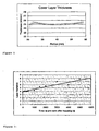
Prior to bonding the 18micron thick lacquer layer on the BD substrate was irradiated with UV light. The UV light was supplied using a light guide 130mm above the centre of the first substrate. At the centre of the disc a UV intensity of around 45mW/cm2 was measured. Due to the geometry, the UV intensity is decreasing to the outside of the disk.
The same light source was used to irradiate the bonded substrates again, immediately after the bonding chamber has been opened (less the 200ms time delay between opening and UV irradiation). The Disk was then transported to a spin coater and the excess lacquer was removed at a spin speed of 5000rpm for 0.2 seconds. After final curing and separation of the stamper substrate, a thickness uniformity was measured as shown infig. 1 . - Another experiment was done to show the effect of a time delay between bonding and post-bonding curing. This time a 50micron bonding layer was adjusted and there was no pre-curing before bonding. Several disks have been prepared with different time delays between vacuum bonding and low UV intensity irradiation. Finally the thickness uniformity was analyzed. As shown in
figure 2 , there is a clear trend towards higher bonding layer thickness variation for an increased curing delay. The disc was not moved in the time before pre-curing.
Claims (7)
- A method for bonding of disk shaped substrates, comprising the steps of:- providing a first and a second substrate to be bonded via respective surfaces,- applying a liquid adhesive to a first surface and a second surface on said first and second substrates,- irradiating the adhesive-lacquered surface of at least one of the substrates with UV light for increasing the viscosity of the lacquer,- joining the substrates in vacuum thereby forming a bonding layer,- irradiating the joined substrates with UV light for increasing the viscosity of the lacquer in between the joined substrates,- placing the joined substrates onto a rotatable chuck,- rotate the joined substrates with a rotation speed > 500rpm,- separate the joined substrates to leave the full bonding layer on one of the substrates,characterized in that the method further includes the transfer of a earlier sputtered layer from a stamper disk onto the first substrate.
- A method according to claim 1, further comprising a step of irradiating the substrates for final hardening of the bonding layer before or after the separation step.
- A method according to claims 1-2, characterized in that a UV intensity is used for the first irradiation step is in a range of 10 to 100mW/cm2.
- A method according to claim 2 or 3 when depending on claim 2, characterized in that one UV source is used for both irradiating steps.
- A method according to claims 1-4, characterized in that the irradiation step after bonding is done within one second after bonding, preferably 0.5s after bonding.
- A method according to claims 1-5, characterized in that two different lacquers are applied on the individual substrates.
- A method according to claims 1-6, wherein the irradiating UV light is being supplied by means of a light-guide.
Applications Claiming Priority (2)
| Application Number | Priority Date | Filing Date | Title |
|---|---|---|---|
| US75314605P | 2005-12-22 | 2005-12-22 | |
| PCT/CH2006/000719 WO2007071094A1 (en) | 2005-12-22 | 2006-12-21 | Method for producing a space layer in between two disks with high uniformity |
Publications (2)
| Publication Number | Publication Date |
|---|---|
| EP1974352A1 EP1974352A1 (en) | 2008-10-01 |
| EP1974352B1 true EP1974352B1 (en) | 2010-06-09 |
Family
ID=37759958
Family Applications (1)
| Application Number | Title | Priority Date | Filing Date |
|---|---|---|---|
| EP06817769A Not-in-force EP1974352B1 (en) | 2005-12-22 | 2006-12-21 | Method for producing a space layer in between two disks with high uniformity |
Country Status (6)
| Country | Link |
|---|---|
| US (1) | US20070154649A1 (en) |
| EP (1) | EP1974352B1 (en) |
| JP (1) | JP2009521066A (en) |
| AT (1) | ATE470935T1 (en) |
| DE (1) | DE602006014872D1 (en) |
| WO (1) | WO2007071094A1 (en) |
Families Citing this family (1)
| Publication number | Priority date | Publication date | Assignee | Title |
|---|---|---|---|---|
| JP2015099622A (en) * | 2012-03-07 | 2015-05-28 | 淀川メデック株式会社 | Method and apparatus for manufacturing optical laminate structure |
Family Cites Families (11)
| Publication number | Priority date | Publication date | Assignee | Title |
|---|---|---|---|---|
| JP3245734B2 (en) * | 1997-01-13 | 2002-01-15 | 大日本インキ化学工業株式会社 | Disc bonding method and apparatus |
| US5879774A (en) * | 1997-12-03 | 1999-03-09 | Eastman Kodak Company | Multilayer laminate elements having an adhesive layer |
| JP3581246B2 (en) * | 1997-12-17 | 2004-10-27 | パイオニア株式会社 | Manufacturing method of bonded optical disk |
| US6117284A (en) * | 1998-09-28 | 2000-09-12 | Wea Manufacturing, Inc. | Dual-layer DVD disc, and method and apparatus for making same |
| US6309496B1 (en) * | 1999-03-04 | 2001-10-30 | Wea Manfacturing Inc. | Method and apparatus for making dual layer DVD discs |
| EP1187122A3 (en) * | 2000-09-12 | 2007-11-28 | Matsushita Electric Industrial Co., Ltd. | Method and apparatus for producing an optical information recording medium, and optical information recording medium |
| US6881964B2 (en) * | 2001-03-01 | 2005-04-19 | Henkel Corporation | Integral filter support and shutter stop for UV curing system |
| JP2003016702A (en) * | 2001-06-29 | 2003-01-17 | Tdk Corp | Producing method of optical information medium |
| JP2003281791A (en) * | 2002-03-22 | 2003-10-03 | Toshiba Corp | Single-sided two layered optical disk and method and device for manufacturing the same |
| US7460463B2 (en) * | 2002-05-10 | 2008-12-02 | Panasonic Corporation | Method of and apparatus for manufacturing multi-layer optical information recording medium |
| JP2005141816A (en) * | 2003-11-05 | 2005-06-02 | Tdk Corp | Method for manufacturing optical recording medium |
-
2006
- 2006-12-21 EP EP06817769A patent/EP1974352B1/en not_active Not-in-force
- 2006-12-21 DE DE602006014872T patent/DE602006014872D1/en active Active
- 2006-12-21 US US11/614,283 patent/US20070154649A1/en not_active Abandoned
- 2006-12-21 AT AT06817769T patent/ATE470935T1/en active
- 2006-12-21 WO PCT/CH2006/000719 patent/WO2007071094A1/en active Application Filing
- 2006-12-21 JP JP2008546070A patent/JP2009521066A/en active Pending
Also Published As
| Publication number | Publication date |
|---|---|
| DE602006014872D1 (en) | 2010-07-22 |
| EP1974352A1 (en) | 2008-10-01 |
| US20070154649A1 (en) | 2007-07-05 |
| ATE470935T1 (en) | 2010-06-15 |
| WO2007071094A1 (en) | 2007-06-28 |
| JP2009521066A (en) | 2009-05-28 |
Similar Documents
| Publication | Publication Date | Title |
|---|---|---|
| JP3988834B2 (en) | Resin layer forming method, resin layer forming apparatus, disc, and disc manufacturing method | |
| KR101067988B1 (en) | Bonding method and bonding apparatus | |
| TWI384476B (en) | Fitting method and fitting device | |
| US8454863B2 (en) | Method of and apparatus for manufacturing multi-layer optical information recording medium | |
| EP1974352B1 (en) | Method for producing a space layer in between two disks with high uniformity | |
| WO2003081584A1 (en) | Multi-layered optical information recording medium manufacturing method | |
| TW200903482A (en) | Bonding method and bonding apparatus | |
| JPH10283682A (en) | Optical disk and its manufacture | |
| JPH04370548A (en) | Production of base body for optical recording disk and device for executing this method | |
| JP4237231B2 (en) | Disc manufacturing method | |
| JP2007226870A (en) | Disk manufacturing method and transfer device | |
| JP2007323769A (en) | Manufacturing method of optical recording medium | |
| JP2005285169A (en) | Manufacturing method of information recording medium and manufacturing device of information recording medium | |
| TW200937411A (en) | Transfer device and transfer method | |
| JP2001338442A (en) | Method and device for manufacturing optical recording medium | |
| EP2091043A1 (en) | A method for examining an optical stamper | |
| JPH11273163A (en) | Method and device for manufacturing laminated disk | |
| JP2005332516A (en) | Manufacturing apparatus and manufacturing method of disk | |
| JP2002230853A (en) | Method of manufacturing optical recording medium | |
| JPH11273161A (en) | Method and device for manufacturing laminated disk | |
| JP2009205743A (en) | Method of manufacturing optical information recording medium and apparatus of manufacturing same | |
| JPH03238631A (en) | Optical recording medium and production thereof | |
| JP2006309892A (en) | Manufacturing method of disk-like recording medium | |
| JP2007149269A (en) | Stamper original plate separating method and its device | |
| JP2004273075A (en) | Manufacturing method for thin film macromolecule laminating medium, and thin film macromolecule laminating medium |
Legal Events
| Date | Code | Title | Description |
|---|---|---|---|
| PUAI | Public reference made under article 153(3) epc to a published international application that has entered the european phase |
Free format text: ORIGINAL CODE: 0009012 |
|
| 17P | Request for examination filed |
Effective date: 20080714 |
|
| AK | Designated contracting states |
Kind code of ref document: A1 Designated state(s): AT BE BG CH CY CZ DE DK EE ES FI FR GB GR HU IE IS IT LI LT LU LV MC NL PL PT RO SE SI SK TR |
|
| RAP1 | Party data changed (applicant data changed or rights of an application transferred) |
Owner name: SINGULUS TECHNOLOGIES AG |
|
| 17Q | First examination report despatched |
Effective date: 20090812 |
|
| R17C | First examination report despatched (corrected) |
Effective date: 20090507 |
|
| GRAP | Despatch of communication of intention to grant a patent |
Free format text: ORIGINAL CODE: EPIDOSNIGR1 |
|
| GRAS | Grant fee paid |
Free format text: ORIGINAL CODE: EPIDOSNIGR3 |
|
| GRAA | (expected) grant |
Free format text: ORIGINAL CODE: 0009210 |
|
| AK | Designated contracting states |
Kind code of ref document: B1 Designated state(s): AT BE BG CH CY CZ DE DK EE ES FI FR GB GR HU IE IS IT LI LT LU LV MC NL PL PT RO SE SI SK TR |
|
| REG | Reference to a national code |
Ref country code: CH Ref legal event code: EP |
|
| REG | Reference to a national code |
Ref country code: IE Ref legal event code: FG4D |
|
| REF | Corresponds to: |
Ref document number: 602006014872 Country of ref document: DE Date of ref document: 20100722 Kind code of ref document: P |
|
| REG | Reference to a national code |
Ref country code: NL Ref legal event code: VDEP Effective date: 20100609 |
|
| PG25 | Lapsed in a contracting state [announced via postgrant information from national office to epo] |
Ref country code: LT Free format text: LAPSE BECAUSE OF FAILURE TO SUBMIT A TRANSLATION OF THE DESCRIPTION OR TO PAY THE FEE WITHIN THE PRESCRIBED TIME-LIMIT Effective date: 20100609 Ref country code: SE Free format text: LAPSE BECAUSE OF FAILURE TO SUBMIT A TRANSLATION OF THE DESCRIPTION OR TO PAY THE FEE WITHIN THE PRESCRIBED TIME-LIMIT Effective date: 20100609 |
|
| LTIE | Lt: invalidation of european patent or patent extension |
Effective date: 20100609 |
|
| PG25 | Lapsed in a contracting state [announced via postgrant information from national office to epo] |
Ref country code: LV Free format text: LAPSE BECAUSE OF FAILURE TO SUBMIT A TRANSLATION OF THE DESCRIPTION OR TO PAY THE FEE WITHIN THE PRESCRIBED TIME-LIMIT Effective date: 20100609 Ref country code: SI Free format text: LAPSE BECAUSE OF FAILURE TO SUBMIT A TRANSLATION OF THE DESCRIPTION OR TO PAY THE FEE WITHIN THE PRESCRIBED TIME-LIMIT Effective date: 20100609 Ref country code: FI Free format text: LAPSE BECAUSE OF FAILURE TO SUBMIT A TRANSLATION OF THE DESCRIPTION OR TO PAY THE FEE WITHIN THE PRESCRIBED TIME-LIMIT Effective date: 20100609 |
|
| PG25 | Lapsed in a contracting state [announced via postgrant information from national office to epo] |
Ref country code: CY Free format text: LAPSE BECAUSE OF FAILURE TO SUBMIT A TRANSLATION OF THE DESCRIPTION OR TO PAY THE FEE WITHIN THE PRESCRIBED TIME-LIMIT Effective date: 20100609 Ref country code: GR Free format text: LAPSE BECAUSE OF FAILURE TO SUBMIT A TRANSLATION OF THE DESCRIPTION OR TO PAY THE FEE WITHIN THE PRESCRIBED TIME-LIMIT Effective date: 20100910 Ref country code: PL Free format text: LAPSE BECAUSE OF FAILURE TO SUBMIT A TRANSLATION OF THE DESCRIPTION OR TO PAY THE FEE WITHIN THE PRESCRIBED TIME-LIMIT Effective date: 20100609 |
|
| PG25 | Lapsed in a contracting state [announced via postgrant information from national office to epo] |
Ref country code: EE Free format text: LAPSE BECAUSE OF FAILURE TO SUBMIT A TRANSLATION OF THE DESCRIPTION OR TO PAY THE FEE WITHIN THE PRESCRIBED TIME-LIMIT Effective date: 20100609 Ref country code: NL Free format text: LAPSE BECAUSE OF FAILURE TO SUBMIT A TRANSLATION OF THE DESCRIPTION OR TO PAY THE FEE WITHIN THE PRESCRIBED TIME-LIMIT Effective date: 20100609 |
|
| PG25 | Lapsed in a contracting state [announced via postgrant information from national office to epo] |
Ref country code: BE Free format text: LAPSE BECAUSE OF FAILURE TO SUBMIT A TRANSLATION OF THE DESCRIPTION OR TO PAY THE FEE WITHIN THE PRESCRIBED TIME-LIMIT Effective date: 20100609 Ref country code: IS Free format text: LAPSE BECAUSE OF FAILURE TO SUBMIT A TRANSLATION OF THE DESCRIPTION OR TO PAY THE FEE WITHIN THE PRESCRIBED TIME-LIMIT Effective date: 20101009 Ref country code: PT Free format text: LAPSE BECAUSE OF FAILURE TO SUBMIT A TRANSLATION OF THE DESCRIPTION OR TO PAY THE FEE WITHIN THE PRESCRIBED TIME-LIMIT Effective date: 20101011 Ref country code: RO Free format text: LAPSE BECAUSE OF FAILURE TO SUBMIT A TRANSLATION OF THE DESCRIPTION OR TO PAY THE FEE WITHIN THE PRESCRIBED TIME-LIMIT Effective date: 20100609 Ref country code: SK Free format text: LAPSE BECAUSE OF FAILURE TO SUBMIT A TRANSLATION OF THE DESCRIPTION OR TO PAY THE FEE WITHIN THE PRESCRIBED TIME-LIMIT Effective date: 20100609 Ref country code: CZ Free format text: LAPSE BECAUSE OF FAILURE TO SUBMIT A TRANSLATION OF THE DESCRIPTION OR TO PAY THE FEE WITHIN THE PRESCRIBED TIME-LIMIT Effective date: 20100609 |
|
| PG25 | Lapsed in a contracting state [announced via postgrant information from national office to epo] |
Ref country code: IT Free format text: LAPSE BECAUSE OF FAILURE TO SUBMIT A TRANSLATION OF THE DESCRIPTION OR TO PAY THE FEE WITHIN THE PRESCRIBED TIME-LIMIT Effective date: 20100609 |
|
| PLBE | No opposition filed within time limit |
Free format text: ORIGINAL CODE: 0009261 |
|
| STAA | Information on the status of an ep patent application or granted ep patent |
Free format text: STATUS: NO OPPOSITION FILED WITHIN TIME LIMIT |
|
| PG25 | Lapsed in a contracting state [announced via postgrant information from national office to epo] |
Ref country code: DK Free format text: LAPSE BECAUSE OF FAILURE TO SUBMIT A TRANSLATION OF THE DESCRIPTION OR TO PAY THE FEE WITHIN THE PRESCRIBED TIME-LIMIT Effective date: 20100609 |
|
| REG | Reference to a national code |
Ref country code: DE Ref legal event code: R097 Ref document number: 602006014872 Country of ref document: DE Effective date: 20110309 |
|
| PG25 | Lapsed in a contracting state [announced via postgrant information from national office to epo] |
Ref country code: MC Free format text: LAPSE BECAUSE OF NON-PAYMENT OF DUE FEES Effective date: 20101231 |
|
| REG | Reference to a national code |
Ref country code: CH Ref legal event code: PL |
|
| GBPC | Gb: european patent ceased through non-payment of renewal fee |
Effective date: 20101221 |
|
| REG | Reference to a national code |
Ref country code: FR Ref legal event code: ST Effective date: 20110831 |
|
| PG25 | Lapsed in a contracting state [announced via postgrant information from national office to epo] |
Ref country code: FR Free format text: LAPSE BECAUSE OF NON-PAYMENT OF DUE FEES Effective date: 20110103 Ref country code: IE Free format text: LAPSE BECAUSE OF NON-PAYMENT OF DUE FEES Effective date: 20101221 Ref country code: CH Free format text: LAPSE BECAUSE OF NON-PAYMENT OF DUE FEES Effective date: 20101231 Ref country code: LI Free format text: LAPSE BECAUSE OF NON-PAYMENT OF DUE FEES Effective date: 20101231 |
|
| PG25 | Lapsed in a contracting state [announced via postgrant information from national office to epo] |
Ref country code: GB Free format text: LAPSE BECAUSE OF NON-PAYMENT OF DUE FEES Effective date: 20101221 |
|
| PG25 | Lapsed in a contracting state [announced via postgrant information from national office to epo] |
Ref country code: LU Free format text: LAPSE BECAUSE OF NON-PAYMENT OF DUE FEES Effective date: 20101221 Ref country code: BG Free format text: LAPSE BECAUSE OF FAILURE TO SUBMIT A TRANSLATION OF THE DESCRIPTION OR TO PAY THE FEE WITHIN THE PRESCRIBED TIME-LIMIT Effective date: 20100609 Ref country code: HU Free format text: LAPSE BECAUSE OF FAILURE TO SUBMIT A TRANSLATION OF THE DESCRIPTION OR TO PAY THE FEE WITHIN THE PRESCRIBED TIME-LIMIT Effective date: 20101210 |
|
| PG25 | Lapsed in a contracting state [announced via postgrant information from national office to epo] |
Ref country code: TR Free format text: LAPSE BECAUSE OF FAILURE TO SUBMIT A TRANSLATION OF THE DESCRIPTION OR TO PAY THE FEE WITHIN THE PRESCRIBED TIME-LIMIT Effective date: 20100609 |
|
| REG | Reference to a national code |
Ref country code: AT Ref legal event code: MM01 Ref document number: 470935 Country of ref document: AT Kind code of ref document: T Effective date: 20111221 |
|
| PG25 | Lapsed in a contracting state [announced via postgrant information from national office to epo] |
Ref country code: AT Free format text: LAPSE BECAUSE OF NON-PAYMENT OF DUE FEES Effective date: 20111221 |
|
| PG25 | Lapsed in a contracting state [announced via postgrant information from national office to epo] |
Ref country code: BG Free format text: LAPSE BECAUSE OF FAILURE TO SUBMIT A TRANSLATION OF THE DESCRIPTION OR TO PAY THE FEE WITHIN THE PRESCRIBED TIME-LIMIT Effective date: 20100909 |
|
| PG25 | Lapsed in a contracting state [announced via postgrant information from national office to epo] |
Ref country code: ES Free format text: LAPSE BECAUSE OF FAILURE TO SUBMIT A TRANSLATION OF THE DESCRIPTION OR TO PAY THE FEE WITHIN THE PRESCRIBED TIME-LIMIT Effective date: 20100920 |
|
| PGFP | Annual fee paid to national office [announced via postgrant information from national office to epo] |
Ref country code: DE Payment date: 20140131 Year of fee payment: 8 |
|
| REG | Reference to a national code |
Ref country code: DE Ref legal event code: R119 Ref document number: 602006014872 Country of ref document: DE |
|
| PG25 | Lapsed in a contracting state [announced via postgrant information from national office to epo] |
Ref country code: DE Free format text: LAPSE BECAUSE OF NON-PAYMENT OF DUE FEES Effective date: 20150701 |