EP1973126A1 - Adjustable primary voltage coil for a dry-type transformer and HV/LV transformer comprising same - Google Patents
Adjustable primary voltage coil for a dry-type transformer and HV/LV transformer comprising same Download PDFInfo
- Publication number
- EP1973126A1 EP1973126A1 EP08354010A EP08354010A EP1973126A1 EP 1973126 A1 EP1973126 A1 EP 1973126A1 EP 08354010 A EP08354010 A EP 08354010A EP 08354010 A EP08354010 A EP 08354010A EP 1973126 A1 EP1973126 A1 EP 1973126A1
- Authority
- EP
- European Patent Office
- Prior art keywords
- power
- wafer
- coil
- transformer
- output
- Prior art date
- Legal status (The legal status is an assumption and is not a legal conclusion. Google has not performed a legal analysis and makes no representation as to the accuracy of the status listed.)
- Granted
Links
- 239000011347 resin Substances 0.000 claims abstract description 10
- 229920005989 resin Polymers 0.000 claims abstract description 10
- 235000012431 wafers Nutrition 0.000 claims description 69
- 238000004804 winding Methods 0.000 claims description 13
- 239000011248 coating agent Substances 0.000 claims description 5
- 238000000576 coating method Methods 0.000 claims description 5
- 238000005096 rolling process Methods 0.000 abstract 1
- 238000004519 manufacturing process Methods 0.000 description 4
- 235000012771 pancakes Nutrition 0.000 description 4
- 239000004020 conductor Substances 0.000 description 3
- 238000009826 distribution Methods 0.000 description 3
- 238000009413 insulation Methods 0.000 description 3
- 238000012423 maintenance Methods 0.000 description 3
- 230000009466 transformation Effects 0.000 description 3
- 238000013461 design Methods 0.000 description 1
- 238000010292 electrical insulation Methods 0.000 description 1
- 239000013529 heat transfer fluid Substances 0.000 description 1
- 238000005470 impregnation Methods 0.000 description 1
- 238000003780 insertion Methods 0.000 description 1
- 230000037431 insertion Effects 0.000 description 1
- 238000002955 isolation Methods 0.000 description 1
- 238000000034 method Methods 0.000 description 1
- 239000002480 mineral oil Substances 0.000 description 1
- 238000012986 modification Methods 0.000 description 1
- 230000004048 modification Effects 0.000 description 1
- 238000000465 moulding Methods 0.000 description 1
Images


Classifications
-
- H—ELECTRICITY
- H01—ELECTRIC ELEMENTS
- H01F—MAGNETS; INDUCTANCES; TRANSFORMERS; SELECTION OF MATERIALS FOR THEIR MAGNETIC PROPERTIES
- H01F29/00—Variable transformers or inductances not covered by group H01F21/00
- H01F29/02—Variable transformers or inductances not covered by group H01F21/00 with tappings on coil or winding; with provision for rearrangement or interconnection of windings
- H01F29/025—Constructional details of transformers or reactors with tapping on coil or windings
-
- H—ELECTRICITY
- H01—ELECTRIC ELEMENTS
- H01F—MAGNETS; INDUCTANCES; TRANSFORMERS; SELECTION OF MATERIALS FOR THEIR MAGNETIC PROPERTIES
- H01F27/00—Details of transformers or inductances, in general
- H01F27/28—Coils; Windings; Conductive connections
- H01F27/2871—Pancake coils
-
- H—ELECTRICITY
- H01—ELECTRIC ELEMENTS
- H01F—MAGNETS; INDUCTANCES; TRANSFORMERS; SELECTION OF MATERIALS FOR THEIR MAGNETIC PROPERTIES
- H01F27/00—Details of transformers or inductances, in general
- H01F27/28—Coils; Windings; Conductive connections
- H01F27/32—Insulating of coils, windings, or parts thereof
- H01F27/327—Encapsulating or impregnating
- H01F2027/328—Dry-type transformer with encapsulated foil winding, e.g. windings coaxially arranged on core legs with spacers for cooling and with three phases
-
- H—ELECTRICITY
- H01—ELECTRIC ELEMENTS
- H01F—MAGNETS; INDUCTANCES; TRANSFORMERS; SELECTION OF MATERIALS FOR THEIR MAGNETIC PROPERTIES
- H01F27/00—Details of transformers or inductances, in general
- H01F27/28—Coils; Windings; Conductive connections
- H01F27/2823—Wires
- H01F27/2828—Construction of conductive connections, of leads
-
- H—ELECTRICITY
- H01—ELECTRIC ELEMENTS
- H01F—MAGNETS; INDUCTANCES; TRANSFORMERS; SELECTION OF MATERIALS FOR THEIR MAGNETIC PROPERTIES
- H01F27/00—Details of transformers or inductances, in general
- H01F27/28—Coils; Windings; Conductive connections
- H01F27/2847—Sheets; Strips
- H01F27/2852—Construction of conductive connections, of leads
-
- H—ELECTRICITY
- H01—ELECTRIC ELEMENTS
- H01F—MAGNETS; INDUCTANCES; TRANSFORMERS; SELECTION OF MATERIALS FOR THEIR MAGNETIC PROPERTIES
- H01F30/00—Fixed transformers not covered by group H01F19/00
- H01F30/06—Fixed transformers not covered by group H01F19/00 characterised by the structure
- H01F30/12—Two-phase, three-phase or polyphase transformers
Abstract
Description
L'invention concerne de manière générale la réalisation de transformateurs de puissance pour la distribution de l'énergie électrique, monophasés ou multiphasés, du type enrobés ou immergés, dans lesquels la tension primaire ou secondaire peut être modulée.The invention generally relates to the realization of power transformers for the distribution of electrical energy, single phase or multiphase, of the coated or immersed type, in which the primary or secondary voltage can be modulated.
En particulier, l'invention se rapporte à une bobine haute tension, souvent externe, pour une partie active d'un transformateur, réalisée sous la forme de galettes empilées dont l'orientation relative permet de modifier la tension d'entrée, ainsi qu'aux galettes adaptées à cet usage.In particular, the invention relates to a high-voltage coil, often external, for an active part of a transformer, made in the form of stacked wafers whose relative orientation makes it possible to modify the input voltage, as well as pancakes adapted for this purpose.
L'invention concerne également des modules de transformateur ainsi que les cellules unitaires de ces modules, formés avec un nombre variable de galettes.The invention also relates to transformer modules and the unit cells of these modules, formed with a variable number of wafers.
Pour la distribution d'énergie, la tension du réseau est usuellement abaissée du niveau « haute tension » (entre 5 et 52 kV) à un niveau « basse tension » (inférieur à 1000 V) ; des transformateurs haute tension/basse tension (HT/BT) permettent cette modification, au prix d'échanges thermiques importants. Classiquement, ces transformateurs utilisent des huiles minérales comme fluide isolant et caloporteur.For power distribution, the grid voltage is usually lowered from the "high voltage" level (between 5 and 52 kV) to a "low voltage" level (less than 1000 V); high voltage / low voltage transformers (HV / LV) allow this modification, at the cost of significant heat exchange. Traditionally, these transformers use mineral oils as insulating and heat transfer fluid.
Afin notamment de préserver l'environnement et d'éviter les risques de feu, des transformateurs dits enrobés, ou à isolation solide, ont été développés dans lesquels les enroulements primaire et secondaire, concentriques, sont chacun noyés dans de la résine diélectrique de moulage. La résine assure, outre l'isolation électrique, les échanges thermiques avec l'air afin de refroidir le transformateur. Les transformateurs de puissance enrobés peuvent en outre être blindés, en particulier au niveau de la bobine HT externe, pour augmenter leur isolement par rapport à l'environnement. Un exemple de réalisation est donné dans le document
Le procédé de réalisation des bobines est cependant lourd, et ce type de transformateur enrobé reste onéreux. En particulier, les enroulements sont fabriqués le plus souvent sur commande à partir d'un cahier des charges du client, notamment en fonction des tensions qu'il souhaite traiter et de la puissance envisagée.The process of producing the coils is however heavy, and this type of coated transformer remains expensive. In particular, the windings are usually manufactured to order from a specification of the customer, particularly depending on the voltages he wishes to treat and the power envisaged.
Parmi autres avantages, l'invention vise à pallier des inconvénients des transformateurs existants en rationalisant la gamme des enroulements, notamment en réalisant des bobines qui peuvent être adaptées à des transformateurs de puissance et/ou tension primaire différentes.Among other advantages, the invention aims to overcome the disadvantages of existing transformers by rationalizing the range of windings, in particular by producing coils that can be adapted to different power transformers and / or primary voltage.
L'invention concerne en particulier une bobine, de préférence la bobine haute tension, réalisée par superposition de galettes de puissance comprenant plusieurs sorties. Suivant la connexion sur une galette et/ou entre deux galettes de puissance consécutives, il est possible d'ajuster la tension d'entrée en augmentant la puissance supportée d'entrée ; suivant le nombre de galettes, il est possible d'ajuster la puissance.The invention relates in particular to a coil, preferably the high-voltage coil, made by superposition of power wafers comprising a plurality of outputs. Depending on the connection on a wafer and / or between two consecutive power wafers, it is possible to adjust the input voltage by increasing the input power input; Depending on the number of slabs, it is possible to adjust the power.
Sous un de ses aspects, l'invention a trait à une galette de puissance enrobée dans une résine isolante et comprenant une entrée et une pluralité de sorties accessibles, de préférence deux, de l'enroulement de spires. Avantageusement, la répartition angulaire des bornes relatives aux entrée/sorties est régulière. De préférence, les entrée/sorties sont accessibles depuis chaque face de la galette grâce à la présence de surmoulages latéraux en résine dans lesquels un dispositif de connexion permet l'insertion d'un connecteur coopérant avec une autre galette. Un exemple préféré concerne deux sorties, par exemple à 6 et 7 kV, et une entrée équidistantes de 120° débouchant dans trois protubérances.In one of its aspects, the invention relates to a power wafer embedded in an insulating resin and having an input and a plurality of accessible outputs, preferably two, of the winding of turns. Advantageously, the angular distribution of the terminals relating to the inputs / outputs is regular. Preferably, the inlets / outlets are accessible from each face of the wafer thanks to the presence of resin side overmoldings in which a connection device allows the insertion of a connector cooperating with another wafer. A preferred example concerns two outputs, for example at 6 and 7 kV, and an equidistant 120 ° input opening into three protuberances.
Sous un autre aspect, l'invention concerne une bobine composée d'une pluralité de galettes de puissance superposées et connectées entre elles en série et/ou en parallèle, l'une des galettes de puissance au moins, de préférence toutes, comprenant une pluralité de sorties de tensions différentes. Avantageusement, toutes les galettes de puissance sont identiques, et notamment comprennent une protubérance pour chaque borne d'entrée et de sortie dans laquelle un connecteur peut être inséré pour directement les relier entre elles ; des bouchons peuvent être mis en place dans les protubérances non électriquement connectées. L'ajustement de la tension primaire est alors réalisé par le choix de la connexion (série ou parallèle) et l'orientation relative des galettes de puissance.In another aspect, the invention relates to a coil composed of a plurality of superimposed power wafers connected together in series and / or in parallel, one of at least one, preferably all, of the power wafers comprising a plurality of different voltage outputs. Advantageously, all the power wafers are identical, and in particular comprise a protrusion for each input and output terminal in which a connector can be inserted to directly connect them; plugs may be placed in the non-electrically connected protuberances. The adjustment of the primary voltage is then achieved by the choice of the connection (series or parallel) and the relative orientation of the power wafers.
Selon un mode de réalisation préféré, une bobine pour transformateur HT/BT selon l'invention comprend plusieurs galettes de puissance à plusieurs sorties superposées, associées à deux galettes d'extrémité, chaque galette d'extrémité comprenant une borne de connexion vers l'extérieur. Les galettes de puissance sont ainsi simplifiées et uniformisées au maximum, et il est possible, par les galettes d'extrémité, de s'adapter aux connectiques externes du client et/ou à la modularité souhaitée des transformateurs.According to a preferred embodiment, an HV / LV transformer coil according to the invention comprises a plurality of superimposed superimposed power wafers, associated with two end wafers, each end wafer comprising an outward connection terminal. . The power wafers are thus simplified and standardized as much as possible, and it is possible, by the end wafers, to adapt to the external connections of the customer and / or to the desired modularity of the transformers.
Les galettes d'extrémité peuvent être identiques de conception, ou l'une d'entre elles peut être dotée de moyens permettant une connexion avec la borne de l'autre galette d'extrémité. L'une des galettes d'extrémité au moins est adaptée pour être connectée avec une autre galette (par exemple la galette d'extrémité d'une autre bobine selon l'invention), et/ou pour le raccordement client.The end wafers may be identical in design, or one of them may be provided with means for connection with the terminal of the other end wafer. At least one of the end slabs is adapted to be connected with another slab (for example the end slab of another spool according to the invention), and / or for the customer connection.
Une bobine HT selon l'invention peut être associée à une bobine BT afin de réaliser une partie active de transformateur. Trois parties actives peuvent être associées à un circuit magnétique de façon à réaliser un module de transformation triphasée.A HV coil according to the invention may be associated with a LV coil in order to produce an active transformer part. Three active parts can be associated with a magnetic circuit so as to produce a three-phase transformation module.
D'autres avantages et caractéristiques ressortiront plus clairement de la description qui suit de modes particuliers de réalisation de l'invention, donnés à titre illustratif et nullement limitatifs, représentés dans les figures annexées.Other advantages and features will emerge more clearly from the following description of particular embodiments of the invention, given by way of illustration and in no way limiting, represented in the appended figures.
La
La
Les
Les
L'invention sera décrite en relation avec un empilement de quatre galettes de puissance identiques comprenant des sorties, en particulier à 6 et 7 kV, espacées de 120° avec une entrée à 0 V de l'enroulement. Ce mode de réalisation est particulièrement avantageux car, tout en ne compliquant pas de façon excessive la fabrication et la maintenance, il permet de couvrir la majorité des applications souhaitées (en particulier les transformateurs de 6, 7, 12, 14, 18, 21, 24, 28 kV). Il apparaîtra cependant clairement à l'homme du métier que cet exemple illustratif peut être adapté à la demande et que, notamment, d'autres choix de tensions de sortie sont envisageables, qu'un nombre différent de galettes peut être empilé, qui chacune peuvent comprendre plus de sorties si désiré, comme par exemple trois sorties espacées de 90°,...The invention will be described in relation to a stack of four identical power wafers comprising outputs, in particular at 6 and 7 kV, spaced by 120 ° with a 0 V input of the winding. This embodiment is particularly advantageous because, while not excessively complicating the manufacture and maintenance, it makes it possible to cover the majority of the desired applications (in particular the transformers of 6, 7, 12, 14, 18, 21, 24.28 kV). However, it will be clear to those skilled in the art that this illustrative example can be adapted to the application and that, in particular, other choices of output voltages are possible, that a different number of wafers can be stacked, each of which can include more outputs if desired, such as three outputs spaced 90 °, ...
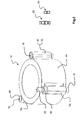
Les galettes de puissance selon l'invention sont utilisées pour la fabrication de bobines HT de transformateur qui entrent dans la composition de transformateurs triphasés. Tel qu'illustré en
Selon l'invention, il est possible d'augmenter la puissance grâce au nombre de galettes 10 mais aussi de multiplier les valeurs des tensions primaires tolérées : au moins une galette de puissance 10, illustrée en
Afin de faciliter les connexions, il est avantageux que les entrées et sorties, que l'on peut aussi qualifier de bornes, soient accessibles en des localisations latérales reproductibles de la galette de puissance 10, par exemple un câble de raccordement peut relier des orifices de sortie similaires à ceux présents dans l'enroulement décrit dans
En particulier, pour le mode de réalisation présenté plus haut, chaque galette de puissance 10 se présente sous la forme d'un anneau de résine 14 dans lequel est noyé l'enroulement de spires, muni de trois protubérances 120, 121, 122 à 120° correspondant respectivement à l'entrée (0 V) de l'enroulement des spires et deux sorties de pas de tension différent, notamment 6 et 7 kV. Les trois protubérances 12 comprennent un orifice 16 à chaque extrémité dans lequel peut être inséré un dispositif de connexion 20 qui peut être conducteur, comme par exemple un bicône 22, ou isolant comme un bouchon 24.In particular, for the embodiment presented above, each
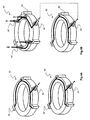
Pour réaliser une bobine 8 de transformateur, les galettes de puissance 10 sont empilées : selon l'ordonnancement des dispositifs de connexion conducteurs 22 dans les protubérances 12i, différentes tensions primaires sont couvertes. Ainsi, tel qu'illustré en
Tel qu'illustré en
Bien que non représenté, l'homme du métier réalisera les modifications dans l'emplacement des connecteurs de ces quatre galettes de puissance, et l'orientation résultante des galettes, pour les autres tensions possibles. De même, selon son besoin, il adaptera le nombre de galettes. Par ailleurs, suivant le nombre de pas de tension de chaque galette de puissance, c'est-à-dire leur nombre de sorties, et pour couvrir toutes les combinaisons de connexions entre sorties, il est possible par exemple de mettre en place un nombre supérieur d'entrées, ou d'utiliser des systèmes plus complexes de connexion, ou de positionner les galettes indifféremment dans les deux sens pile et face.Although not shown, those skilled in the art will make changes in the location of the connectors of these four power wafers, and the resulting orientation of the wafers, for other possible voltages. Likewise, according to his need, he will adapt the number of pancakes. Furthermore, depending on the number of voltage steps of each power wafer, that is to say their number of outputs, and to cover all the combinations of connections between outputs, it is possible for example to set up a number higher inputs, or use more complex systems of connection, or to position the pancakes indifferently in both directions stack and face.
Afin de faciliter la mise en place de la partie active du transformateur et notamment de standardiser et stabiliser les connexions d'entrée et sortie de la bobine HT 8, il est souhaitable de réaliser en outre des galettes d'extrémité 50 isolées mises en place sur les faces d'extrémité de la bobine 30, 40. En particulier, chaque galette d'extrémité 50 comprend des protubérances 52 similaires à celles des galettes de puissance 10, dotées d'orifices, qui avantageusement ne débouchent que sur une face, dans lesquels des moyens de liaison comme les bicônes 22 et les bouchons 24 peuvent être insérés ; les orifices sont eux aussi munis d'un système permettant la conduction électrique, par exemple de nature similaire à celui des galettes de puissance 10 (bagues 18,...). Les galettes d'extrémité comprennent en outre une ou plusieurs bornes d'entrée et/ou sortie 54 permettant la connexion plus « classique » vers des systèmes extérieurs (câbles de raccordement, autre galette,...) ; les bornes d'amenée de courant 54 peuvent être latérales ou localisées sur une face de la galette 50. Il est possible, selon l'ordonnancement des modules de transformateur, que les galettes d'extrémité soient alors à orientation fixe.In order to facilitate the setting up of the active part of the transformer and in particular to standardize and stabilize the input and output connections of the
Selon un premier mode de réalisation préféré illustré en
Il peut être avantageux, selon un autre mode de réalisation préféré illustré en
Il est entendu que les différents modes de réalisation, pour les connexions et les bornes notamment, peuvent être combinés selon le cahier des charges et l'encombrement. De même, des alternatives sont possibles.It is understood that the different embodiments, for connections and terminals in particular, can be combined according to the specifications and the size. Similarly, alternatives are possible.
L'invention permet, entre autres avantages, de :
- réaliser plusieurs modèles de transformateurs (puissance, tension primaire, système de connexion,...) avec peu de références industrielles ;
- réduire les délais et les coûts de fabrication par l'optimisation de l'outil industriel ;
- réduire les délais de livraison grâce à un assemblage sur des stocks que l'on peut optimiser ;
- réaliser un système permettant d'augmenter la VA locale, notamment en distribuant les pièces composant le transformateur individuellement et en les assemblant sur place ;
- réduire les coûts de maintenance, les bobines étant interchangeables.
- realize several models of transformers (power, primary voltage, connection system, ...) with few industrial references;
- reduce manufacturing time and costs by optimizing the industrial tool;
- reduce delivery times by assembling inventory that can be optimized;
- implement a system to increase the local VA, including distributing transformer component parts individually and assembling them locally;
- reduce maintenance costs, the coils being interchangeable.
Claims (11)
Applications Claiming Priority (1)
| Application Number | Priority Date | Filing Date | Title |
|---|---|---|---|
| FR0702010A FR2914105B1 (en) | 2007-03-20 | 2007-03-20 | ADJUSTABLE PRIMARY VOLTAGE COIL FOR DRY TRANSFORMER AND HT / LV TRANSFORMER COMPRISING SAME |
Publications (2)
| Publication Number | Publication Date |
|---|---|
| EP1973126A1 true EP1973126A1 (en) | 2008-09-24 |
| EP1973126B1 EP1973126B1 (en) | 2009-07-08 |
Family
ID=38434696
Family Applications (1)
| Application Number | Title | Priority Date | Filing Date |
|---|---|---|---|
| EP08354010A Active EP1973126B1 (en) | 2007-03-20 | 2008-02-04 | Adjustable primary voltage coil for a dry-type transformer and HV/LV transformer comprising same |
Country Status (5)
| Country | Link |
|---|---|
| EP (1) | EP1973126B1 (en) |
| AT (1) | ATE436078T1 (en) |
| DE (1) | DE602008000039D1 (en) |
| ES (1) | ES2326846T3 (en) |
| FR (1) | FR2914105B1 (en) |
Cited By (2)
| Publication number | Priority date | Publication date | Assignee | Title |
|---|---|---|---|---|
| EP2063494A1 (en) | 2007-11-20 | 2009-05-27 | Schneider Electric Industries SAS | Shielded connection of two terminals by contact between flat interfaces |
| EP2189990A1 (en) * | 2008-11-22 | 2010-05-26 | ABB Technology AG | Single phase winding module and arrangement of single phase winding modules |
Citations (7)
| Publication number | Priority date | Publication date | Assignee | Title |
|---|---|---|---|---|
| FR702011A (en) | 1930-08-14 | 1931-03-27 | Houtindustrie Picus Voorheen J | Process for manufacturing objects or materials coated with an artificial resin on their surface |
| FR1578613A (en) * | 1968-08-30 | 1969-08-14 | ||
| US4586015A (en) * | 1982-06-29 | 1986-04-29 | Hitachi, Ltd. | Transformer with a surface shield layer |
| FR2637729A1 (en) * | 1988-10-07 | 1990-04-13 | Transfix Soc Nouv | Dry insulation high voltage/low voltage distribution transformer and process for producing such a transformer |
| FR2673484A1 (en) * | 1991-03-01 | 1992-09-04 | Thomson Csf | High-voltage power supply device, intended particularly for an X-ray generator, method of manufacturing a high-voltage transformer and X-ray generator employing such a transformer |
| WO1998010446A1 (en) | 1996-09-04 | 1998-03-12 | E.I. Du Pont De Nemours And Company | Air-core primary voltage winding |
| FR2822587A1 (en) * | 2001-03-20 | 2002-09-27 | France Transfo Sa | High voltage power/distribution transformer having cylindrical crown shape winding with dielectric envelope conductor with windings formed stacking pancake layers stuck together. |
-
2007
- 2007-03-20 FR FR0702010A patent/FR2914105B1/en not_active Expired - Fee Related
-
2008
- 2008-02-04 EP EP08354010A patent/EP1973126B1/en active Active
- 2008-02-04 ES ES08354010T patent/ES2326846T3/en active Active
- 2008-02-04 DE DE602008000039T patent/DE602008000039D1/en active Active
- 2008-02-04 AT AT08354010T patent/ATE436078T1/en not_active IP Right Cessation
Patent Citations (7)
| Publication number | Priority date | Publication date | Assignee | Title |
|---|---|---|---|---|
| FR702011A (en) | 1930-08-14 | 1931-03-27 | Houtindustrie Picus Voorheen J | Process for manufacturing objects or materials coated with an artificial resin on their surface |
| FR1578613A (en) * | 1968-08-30 | 1969-08-14 | ||
| US4586015A (en) * | 1982-06-29 | 1986-04-29 | Hitachi, Ltd. | Transformer with a surface shield layer |
| FR2637729A1 (en) * | 1988-10-07 | 1990-04-13 | Transfix Soc Nouv | Dry insulation high voltage/low voltage distribution transformer and process for producing such a transformer |
| FR2673484A1 (en) * | 1991-03-01 | 1992-09-04 | Thomson Csf | High-voltage power supply device, intended particularly for an X-ray generator, method of manufacturing a high-voltage transformer and X-ray generator employing such a transformer |
| WO1998010446A1 (en) | 1996-09-04 | 1998-03-12 | E.I. Du Pont De Nemours And Company | Air-core primary voltage winding |
| FR2822587A1 (en) * | 2001-03-20 | 2002-09-27 | France Transfo Sa | High voltage power/distribution transformer having cylindrical crown shape winding with dielectric envelope conductor with windings formed stacking pancake layers stuck together. |
Cited By (3)
| Publication number | Priority date | Publication date | Assignee | Title |
|---|---|---|---|---|
| EP2063494A1 (en) | 2007-11-20 | 2009-05-27 | Schneider Electric Industries SAS | Shielded connection of two terminals by contact between flat interfaces |
| CN101442163B (en) * | 2007-11-20 | 2013-11-06 | 施耐德电器工业公司 | Shielded connection of two terminals by contact between flat interfaces |
| EP2189990A1 (en) * | 2008-11-22 | 2010-05-26 | ABB Technology AG | Single phase winding module and arrangement of single phase winding modules |
Also Published As
| Publication number | Publication date |
|---|---|
| EP1973126B1 (en) | 2009-07-08 |
| DE602008000039D1 (en) | 2009-08-20 |
| FR2914105B1 (en) | 2009-04-24 |
| FR2914105A1 (en) | 2008-09-26 |
| ES2326846T3 (en) | 2009-10-20 |
| ATE436078T1 (en) | 2009-07-15 |
Similar Documents
| Publication | Publication Date | Title |
|---|---|---|
| EP2359422A1 (en) | System for assembling electrical energy modules | |
| EP3123597B1 (en) | Interconnection element for connecting stator coils | |
| CN108780872B (en) | Battery and method for producing a battery | |
| FR3075502B1 (en) | STATOR FOR ROTATING ELECTRIC MACHINE | |
| US20200036254A1 (en) | Contact ring for a stator of an electric motor | |
| EP3624188A1 (en) | Power overlay architecture | |
| EP1973126B1 (en) | Adjustable primary voltage coil for a dry-type transformer and HV/LV transformer comprising same | |
| EP3682531A1 (en) | Connection system for an electrical machine | |
| EP2984663B1 (en) | Transformer provided with means for adjusting the in-load transformation ratio | |
| US11688552B2 (en) | Method for assembling a magnetic inductor and magnetic inductor able to be obtained by means of such a method | |
| CA2839489A1 (en) | Three-phase electrical can capacitor with three star-connected capacitances in a housing | |
| EP3756933B1 (en) | Charging connector and charging connection system | |
| EP1973127A1 (en) | Live part of an encapsulated transformer equipped with a connection system at one end and modular HV/LV transformer including same | |
| EP2439808B1 (en) | Device for the electrical connection of battery modules | |
| US20210050681A1 (en) | Cable Assembly and Method for Producing an Electric and Mechanical Connection | |
| KR102173866B1 (en) | Charge and discharge module with super capacitor | |
| EP3790028A1 (en) | Multi-secondary transformer | |
| EP4129021A1 (en) | Electronic circuit | |
| EP4349640A1 (en) | Equipment for charging electric energy storage units of vehicles | |
| WO2024056976A1 (en) | Winding for a planar transformer | |
| WO2022106370A1 (en) | Electrical device with two groups of coupled coils supported by a printed circuit board, voltage converter comprising such an electrical device and method for manufacturing same | |
| WO2021116632A1 (en) | Electrotechnical device for an aircraft | |
| JP2024501363A (en) | Charging system, voltage conversion unit, storage unit | |
| EP4164063A1 (en) | Terminal block | |
| EP4173127A1 (en) | Dc/dc voltage converter comprising an upper module and a lower module |
Legal Events
| Date | Code | Title | Description |
|---|---|---|---|
| PUAI | Public reference made under article 153(3) epc to a published international application that has entered the european phase |
Free format text: ORIGINAL CODE: 0009012 |
|
| AK | Designated contracting states |
Kind code of ref document: A1 Designated state(s): AT BE BG CH CY CZ DE DK EE ES FI FR GB GR HR HU IE IS IT LI LT LU LV MC MT NL NO PL PT RO SE SI SK TR |
|
| AX | Request for extension of the european patent |
Extension state: AL BA MK RS |
|
| 17P | Request for examination filed |
Effective date: 20081007 |
|
| GRAP | Despatch of communication of intention to grant a patent |
Free format text: ORIGINAL CODE: EPIDOSNIGR1 |
|
| RAP1 | Party data changed (applicant data changed or rights of an application transferred) |
Owner name: SCHNEIDER ELECTRIC INDUSTRIES SAS |
|
| AKX | Designation fees paid |
Designated state(s): AT BE BG CH CY CZ DE DK EE ES FI FR GB GR HR HU IE IS IT LI LT LU LV MC MT NL NO PL PT RO SE SI SK TR |
|
| GRAS | Grant fee paid |
Free format text: ORIGINAL CODE: EPIDOSNIGR3 |
|
| GRAA | (expected) grant |
Free format text: ORIGINAL CODE: 0009210 |
|
| AK | Designated contracting states |
Kind code of ref document: B1 Designated state(s): AT BE BG CH CY CZ DE DK EE ES FI FR GB GR HR HU IE IS IT LI LT LU LV MC MT NL NO PL PT RO SE SI SK TR |
|
| REG | Reference to a national code |
Ref country code: GB Ref legal event code: FG4D Free format text: NOT ENGLISH |
|
| REG | Reference to a national code |
Ref country code: CH Ref legal event code: EP |
|
| REG | Reference to a national code |
Ref country code: IE Ref legal event code: FG4D |
|
| REF | Corresponds to: |
Ref document number: 602008000039 Country of ref document: DE Date of ref document: 20090820 Kind code of ref document: P |
|
| REG | Reference to a national code |
Ref country code: ES Ref legal event code: FG2A Ref document number: 2326846 Country of ref document: ES Kind code of ref document: T3 |
|
| PG25 | Lapsed in a contracting state [announced via postgrant information from national office to epo] |
Ref country code: SI Free format text: LAPSE BECAUSE OF FAILURE TO SUBMIT A TRANSLATION OF THE DESCRIPTION OR TO PAY THE FEE WITHIN THE PRESCRIBED TIME-LIMIT Effective date: 20090708 |
|
| NLV1 | Nl: lapsed or annulled due to failure to fulfill the requirements of art. 29p and 29m of the patents act | ||
| PG25 | Lapsed in a contracting state [announced via postgrant information from national office to epo] |
Ref country code: LT Free format text: LAPSE BECAUSE OF FAILURE TO SUBMIT A TRANSLATION OF THE DESCRIPTION OR TO PAY THE FEE WITHIN THE PRESCRIBED TIME-LIMIT Effective date: 20090708 Ref country code: IS Free format text: LAPSE BECAUSE OF FAILURE TO SUBMIT A TRANSLATION OF THE DESCRIPTION OR TO PAY THE FEE WITHIN THE PRESCRIBED TIME-LIMIT Effective date: 20091108 Ref country code: FI Free format text: LAPSE BECAUSE OF FAILURE TO SUBMIT A TRANSLATION OF THE DESCRIPTION OR TO PAY THE FEE WITHIN THE PRESCRIBED TIME-LIMIT Effective date: 20090708 Ref country code: AT Free format text: LAPSE BECAUSE OF FAILURE TO SUBMIT A TRANSLATION OF THE DESCRIPTION OR TO PAY THE FEE WITHIN THE PRESCRIBED TIME-LIMIT Effective date: 20090708 Ref country code: NO Free format text: LAPSE BECAUSE OF FAILURE TO SUBMIT A TRANSLATION OF THE DESCRIPTION OR TO PAY THE FEE WITHIN THE PRESCRIBED TIME-LIMIT Effective date: 20091008 |
|
| REG | Reference to a national code |
Ref country code: IE Ref legal event code: FD4D |
|
| PG25 | Lapsed in a contracting state [announced via postgrant information from national office to epo] |
Ref country code: NL Free format text: LAPSE BECAUSE OF FAILURE TO SUBMIT A TRANSLATION OF THE DESCRIPTION OR TO PAY THE FEE WITHIN THE PRESCRIBED TIME-LIMIT Effective date: 20090708 Ref country code: PL Free format text: LAPSE BECAUSE OF FAILURE TO SUBMIT A TRANSLATION OF THE DESCRIPTION OR TO PAY THE FEE WITHIN THE PRESCRIBED TIME-LIMIT Effective date: 20090708 Ref country code: LV Free format text: LAPSE BECAUSE OF FAILURE TO SUBMIT A TRANSLATION OF THE DESCRIPTION OR TO PAY THE FEE WITHIN THE PRESCRIBED TIME-LIMIT Effective date: 20090708 Ref country code: HR Free format text: LAPSE BECAUSE OF FAILURE TO SUBMIT A TRANSLATION OF THE DESCRIPTION OR TO PAY THE FEE WITHIN THE PRESCRIBED TIME-LIMIT Effective date: 20090708 |
|
| PG25 | Lapsed in a contracting state [announced via postgrant information from national office to epo] |
Ref country code: BG Free format text: LAPSE BECAUSE OF FAILURE TO SUBMIT A TRANSLATION OF THE DESCRIPTION OR TO PAY THE FEE WITHIN THE PRESCRIBED TIME-LIMIT Effective date: 20091008 |
|
| PG25 | Lapsed in a contracting state [announced via postgrant information from national office to epo] |
Ref country code: DK Free format text: LAPSE BECAUSE OF FAILURE TO SUBMIT A TRANSLATION OF THE DESCRIPTION OR TO PAY THE FEE WITHIN THE PRESCRIBED TIME-LIMIT Effective date: 20090708 Ref country code: IE Free format text: LAPSE BECAUSE OF FAILURE TO SUBMIT A TRANSLATION OF THE DESCRIPTION OR TO PAY THE FEE WITHIN THE PRESCRIBED TIME-LIMIT Effective date: 20090708 Ref country code: RO Free format text: LAPSE BECAUSE OF FAILURE TO SUBMIT A TRANSLATION OF THE DESCRIPTION OR TO PAY THE FEE WITHIN THE PRESCRIBED TIME-LIMIT Effective date: 20090708 Ref country code: CZ Free format text: LAPSE BECAUSE OF FAILURE TO SUBMIT A TRANSLATION OF THE DESCRIPTION OR TO PAY THE FEE WITHIN THE PRESCRIBED TIME-LIMIT Effective date: 20090708 Ref country code: EE Free format text: LAPSE BECAUSE OF FAILURE TO SUBMIT A TRANSLATION OF THE DESCRIPTION OR TO PAY THE FEE WITHIN THE PRESCRIBED TIME-LIMIT Effective date: 20090708 |
|
| PLBE | No opposition filed within time limit |
Free format text: ORIGINAL CODE: 0009261 |
|
| STAA | Information on the status of an ep patent application or granted ep patent |
Free format text: STATUS: NO OPPOSITION FILED WITHIN TIME LIMIT |
|
| PG25 | Lapsed in a contracting state [announced via postgrant information from national office to epo] |
Ref country code: SK Free format text: LAPSE BECAUSE OF FAILURE TO SUBMIT A TRANSLATION OF THE DESCRIPTION OR TO PAY THE FEE WITHIN THE PRESCRIBED TIME-LIMIT Effective date: 20090708 |
|
| 26N | No opposition filed |
Effective date: 20100409 |
|
| BERE | Be: lapsed |
Owner name: SCHNEIDER ELECTRIC INDUSTRIES SAS Effective date: 20100228 |
|
| PG25 | Lapsed in a contracting state [announced via postgrant information from national office to epo] |
Ref country code: MC Free format text: LAPSE BECAUSE OF NON-PAYMENT OF DUE FEES Effective date: 20100301 Ref country code: GR Free format text: LAPSE BECAUSE OF FAILURE TO SUBMIT A TRANSLATION OF THE DESCRIPTION OR TO PAY THE FEE WITHIN THE PRESCRIBED TIME-LIMIT Effective date: 20091009 |
|
| PG25 | Lapsed in a contracting state [announced via postgrant information from national office to epo] |
Ref country code: BE Free format text: LAPSE BECAUSE OF NON-PAYMENT OF DUE FEES Effective date: 20100228 |
|
| PG25 | Lapsed in a contracting state [announced via postgrant information from national office to epo] |
Ref country code: MT Free format text: LAPSE BECAUSE OF FAILURE TO SUBMIT A TRANSLATION OF THE DESCRIPTION OR TO PAY THE FEE WITHIN THE PRESCRIBED TIME-LIMIT Effective date: 20090708 |
|
| PGFP | Annual fee paid to national office [announced via postgrant information from national office to epo] |
Ref country code: TR Payment date: 20120113 Year of fee payment: 5 |
|
| PGFP | Annual fee paid to national office [announced via postgrant information from national office to epo] |
Ref country code: GB Payment date: 20120201 Year of fee payment: 5 Ref country code: IT Payment date: 20120215 Year of fee payment: 5 |
|
| PG25 | Lapsed in a contracting state [announced via postgrant information from national office to epo] |
Ref country code: CY Free format text: LAPSE BECAUSE OF FAILURE TO SUBMIT A TRANSLATION OF THE DESCRIPTION OR TO PAY THE FEE WITHIN THE PRESCRIBED TIME-LIMIT Effective date: 20090708 |
|
| PG25 | Lapsed in a contracting state [announced via postgrant information from national office to epo] |
Ref country code: HU Free format text: LAPSE BECAUSE OF FAILURE TO SUBMIT A TRANSLATION OF THE DESCRIPTION OR TO PAY THE FEE WITHIN THE PRESCRIBED TIME-LIMIT Effective date: 20100109 Ref country code: SE Free format text: LAPSE BECAUSE OF FAILURE TO SUBMIT A TRANSLATION OF THE DESCRIPTION OR TO PAY THE FEE WITHIN THE PRESCRIBED TIME-LIMIT Effective date: 20090708 Ref country code: LU Free format text: LAPSE BECAUSE OF NON-PAYMENT OF DUE FEES Effective date: 20100204 Ref country code: PT Free format text: LAPSE BECAUSE OF FAILURE TO SUBMIT A TRANSLATION OF THE DESCRIPTION OR TO PAY THE FEE WITHIN THE PRESCRIBED TIME-LIMIT Effective date: 20091208 |
|
| REG | Reference to a national code |
Ref country code: CH Ref legal event code: PL |
|
| PG25 | Lapsed in a contracting state [announced via postgrant information from national office to epo] |
Ref country code: LI Free format text: LAPSE BECAUSE OF NON-PAYMENT OF DUE FEES Effective date: 20120229 Ref country code: CH Free format text: LAPSE BECAUSE OF NON-PAYMENT OF DUE FEES Effective date: 20120229 |
|
| GBPC | Gb: european patent ceased through non-payment of renewal fee |
Effective date: 20130204 |
|
| PG25 | Lapsed in a contracting state [announced via postgrant information from national office to epo] |
Ref country code: IT Free format text: LAPSE BECAUSE OF NON-PAYMENT OF DUE FEES Effective date: 20130204 |
|
| PG25 | Lapsed in a contracting state [announced via postgrant information from national office to epo] |
Ref country code: GB Free format text: LAPSE BECAUSE OF NON-PAYMENT OF DUE FEES Effective date: 20130204 |
|
| PG25 | Lapsed in a contracting state [announced via postgrant information from national office to epo] |
Ref country code: TR Free format text: LAPSE BECAUSE OF NON-PAYMENT OF DUE FEES Effective date: 20130204 |
|
| REG | Reference to a national code |
Ref country code: FR Ref legal event code: PLFP Year of fee payment: 9 |
|
| REG | Reference to a national code |
Ref country code: FR Ref legal event code: PLFP Year of fee payment: 10 |
|
| REG | Reference to a national code |
Ref country code: FR Ref legal event code: PLFP Year of fee payment: 11 |
|
| PGFP | Annual fee paid to national office [announced via postgrant information from national office to epo] |
Ref country code: FR Payment date: 20230223 Year of fee payment: 16 Ref country code: ES Payment date: 20230323 Year of fee payment: 16 |
|
| PGFP | Annual fee paid to national office [announced via postgrant information from national office to epo] |
Ref country code: ES Payment date: 20240307 Year of fee payment: 17 |
|
| PGFP | Annual fee paid to national office [announced via postgrant information from national office to epo] |
Ref country code: DE Payment date: 20240228 Year of fee payment: 17 |