EP1973107A1 - Voice coil motor and magnetic circuit therefor - Google Patents
Voice coil motor and magnetic circuit therefor Download PDFInfo
- Publication number
- EP1973107A1 EP1973107A1 EP08250967A EP08250967A EP1973107A1 EP 1973107 A1 EP1973107 A1 EP 1973107A1 EP 08250967 A EP08250967 A EP 08250967A EP 08250967 A EP08250967 A EP 08250967A EP 1973107 A1 EP1973107 A1 EP 1973107A1
- Authority
- EP
- European Patent Office
- Prior art keywords
- magnet
- yoke
- yokes
- voice coil
- pair
- Prior art date
- Legal status (The legal status is an assumption and is not a legal conclusion. Google has not performed a legal analysis and makes no representation as to the accuracy of the status listed.)
- Granted
Links
Images


Classifications
-
- H—ELECTRICITY
- H02—GENERATION; CONVERSION OR DISTRIBUTION OF ELECTRIC POWER
- H02K—DYNAMO-ELECTRIC MACHINES
- H02K1/00—Details of the magnetic circuit
- H02K1/06—Details of the magnetic circuit characterised by the shape, form or construction
-
- G—PHYSICS
- G11—INFORMATION STORAGE
- G11B—INFORMATION STORAGE BASED ON RELATIVE MOVEMENT BETWEEN RECORD CARRIER AND TRANSDUCER
- G11B5/00—Recording by magnetisation or demagnetisation of a record carrier; Reproducing by magnetic means; Record carriers therefor
- G11B5/48—Disposition or mounting of heads or head supports relative to record carriers ; arrangements of heads, e.g. for scanning the record carrier to increase the relative speed
- G11B5/54—Disposition or mounting of heads or head supports relative to record carriers ; arrangements of heads, e.g. for scanning the record carrier to increase the relative speed with provision for moving the head into or out of its operative position or across tracks
- G11B5/55—Track change, selection or acquisition by displacement of the head
- G11B5/5521—Track change, selection or acquisition by displacement of the head across disk tracks
- G11B5/5569—Track change, selection or acquisition by displacement of the head across disk tracks details of specially adapted mobile parts, e.g. electromechanical control devices
-
- G—PHYSICS
- G11—INFORMATION STORAGE
- G11B—INFORMATION STORAGE BASED ON RELATIVE MOVEMENT BETWEEN RECORD CARRIER AND TRANSDUCER
- G11B21/00—Head arrangements not specific to the method of recording or reproducing
- G11B21/02—Driving or moving of heads
-
- H—ELECTRICITY
- H02—GENERATION; CONVERSION OR DISTRIBUTION OF ELECTRIC POWER
- H02K—DYNAMO-ELECTRIC MACHINES
- H02K33/00—Motors with reciprocating, oscillating or vibrating magnet, armature or coil system
- H02K33/18—Motors with reciprocating, oscillating or vibrating magnet, armature or coil system with coil systems moving upon intermittent or reversed energisation thereof by interaction with a fixed field system, e.g. permanent magnets
Definitions
- This invention relates to voice coil motors for head positioning in magnetic disk units, and magnetic circuits for use therein.
- a hard disk unit includes a medium having a magnetic recording film deposited thereon, a spindle motor for rotating the medium at a predetermined rotational speed, a magnetic head for writing and reading information data, a voice coil motor (VCM) for driving the magnetic head, a controller and the like.
- VCM voice coil motor
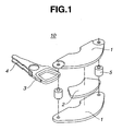
- a voice coil motor 10 includes magnetic material yokes 1, 1 and magnets (permanent magnets) 2 adhesively disposed thereon as described in JP-A 2004-23969 . It is noted that the magnet adhesively disposed on the upper yoke 1 is omitted in FIG. 1 for simplicity of illustration.
- the yokes 1, 1 are opposed and coupled by magnetic material posts 5 such that magnets 2 face each other to define a space therebetween.
- a moving coil 3 on an arm 4 is located in the space between magnets 2.
- the voice coil motor 10 has a function of positioning a magnetic head. After magnets 2 are disposed on yokes 1, they are magnetized so as to produce alternate magnetic poles in the order of N and S.
- a magnetic disk unit 20 which includes a generally rectangular housing 22 for receiving a magnetic disk 21.
- the disk unit 20 further includes a pivot 23, an arm 24, a magnetic head actuator 25, and a suspension 26.
- the voice coil motor 10 is typically disposed at one corner of housing 22.
- the yoke 1 is configured to (1) a triangular shape, typically right-angled triangular shape, including side portions 11, 11 opposed to the adjacent walls defining the one corner of the rectangular housing 22, an apex 12 defined by side portions 11, 11, and a bottom 13 opposed to apex 12, (2) a frusto-triangular shape in which the apex of a triangle is truncated or rounded, or (3) an arcuate, crescent or semi-circular ring shape in which the bottom of a triangle at its center is recessed or cut-off in a semi-circular, triangular or apex-rounded triangular form.
- the magnet is also configured in conformity to the yoke 1, specifically to an arcuate, truncated arcuate or truncated inverse-V shape as illustrated in FIG. 3 .
- a mold of a corresponding shape must be prepared and worked such as by shaping, cutting, grinding or otherwise machining, which operation is expensive and less productive.
- a magnet of an arcuate or similar shape it is difficult to secure the magnet to the yoke at the registered position. A problem arises particularly in a compact magnetic disk unit because the accuracy of magnet registration has a substantial influence on the torque.
- a preferred embodiment of the invention is a magnetic circuit for a voice coil motor which may offer one or more advantages such as more accurate positioning of a magnetic head, minimized torque variation, and highly effective magnet production; and a voice coil motor.
- the invention provides a magnetic circuit and a voice coil motor as defined below.
- Combination of a magnet of rectangular prism or parallelepiped prism shape with a yoke and a coil of proper shape may provide a magnetic circuit which may facilitate positioning and holding of the coil.
- the voice coil motor may be more accurate in positioning the magnetic head.
- a voice coil motor (VCM) according to one embodiment of the invention is illustrated.
- the magnetic circuit of the invention is composed essentially of magnetic material yokes and magnets.
- the VCM includes a pair of yokes 1a, 1b having magnets 2a, 2b adhesively attached thereto.
- the yokes 1a, 1b are coupled and spaced apart by posts 5, 5 of magnetic material such that magnets 2a, 2b face each other.
- a moving coil 3 is inserted into the space between magnets 2a, 2b to construct the VCM.
- the VCM is characterized in that one magnet of rectangular prism or parallelepiped prism shape is disposed on each yoke; or two magnet pieces of rectangular prism or parallelepiped prism shape are serially arranged on each yoke so that the magnet pieces produce alternate magnetic poles.
- the yoke has a shape that fits in the magnetic disk unit and is disposed at one corner of a rectangular shaped housing for receiving a magnetic disk.
- the yoke is generally configured to a triangular shape, a frusto-triangular shape in which the apex of a triangle is truncated or rounded, or an arcuate, crescent or semi-circular ring shape in which the bottom of a triangle at its center is recessed or cut-off in a semi-circular, triangular or apex-rounded triangular form.
- the yoke is made of a magnetic material such as silicon steel or carbon steel and usually provided at lateral ends with holes through which posts or bolts are fitted to couple magnetic circuits together.
- a magnet is registered and adhesively attached onto the yoke.
- the magnet has a rectangular prism or parallelepiped prism shape, which facilitates registration of the magnet relative to the yoke.
- registration of the magnet relative to the yoke is less easy, and any misregistration leads to a problem of torque variations.
- magnet piece 2 is preferably disposed on yoke 1 such that the longitudinal direction of magnet piece 2 is parallel or substantially parallel to a bottom 13 of yoke 1 (i.e., a straight line connecting the lower ends of two oblique sides 11, 11).
- two magnet pieces 2a, 2a are preferably arranged in series such that the longitudinal direction of magnet pieces 2 is parallel to bottom 13 of yoke 1.
- a magnet piece of rectangular or parallelepiped prism shape has a pair of major surfaces, a pair of end faces, and a pair of side faces.
- FIG. 5A and 5B illustrates one embodiment wherein two magnet pieces are arranged side by side with their end faces in abutment.
- FIG. 6A and 6B illustrates another embodiment wherein two magnet pieces are arranged so as to leave a gap 7 between their end faces. Except for the arrangement of magnet pieces, the construction of these embodiments is the same as in the magnetic circuit and VCM of FIGS. 4A and 4B .
- FIGS. 7 to 9 illustrates one embodiment wherein a monolithic magnet 2a is disposed on only one yoke 1a; FIG. 7
- FIG. 8 illustrates another embodiment wherein two magnet pieces 2a, 2a in abutment are serially arranged on only one yoke 1a
- FIG. 9 illustrates a further embodiment wherein two magnet pieces 2a, 2a are serially arranged on only one yoke 1a so as to leave a gap 7 therebetween.
- the number of magnet pieces on each yoke is one or two as mentioned above. In the case of one magnet piece, it is magnetized so as to produce alternate magnetic poles in a planar direction. In the case of two magnet pieces, each piece is magnetized in a thickness direction to produce N and S poles on their surface, and two pieces are arranged in series so that N and S poles alternate in a plan view.
- the arrangement of two magnet pieces may be adjusted such that the distance between the magnet pieces may range from zero to a suitable value, depending on the deflection range or amplitude of the moving coil.
- heat resistant adhesives such as epoxy resins or acrylic resins are preferably used.
- the magnet may be attached to the yoke by the attractive force of the magnet without resorting to the adhesive.
- the magnet used herein may have a rectangular prism or parallelepiped prism shape as mentioned above, with the rectangular prism shape being preferred from the working aspect.
- Ordinary magnets used in the industry include sintered magnets prepared from magnetizable raw materials by melting, grinding, molding and sintering, and bonded magnets prepared by melting, grinding, and resin-aided molding. This is also true in the invention.
- the molded part When a rectangular mold is used in the molding step, the molded part may be easily machined to the desired hexahedral structure. Then the yield of magnet working is improved. Magnets may be worked into a rectangular shape using a peripheral milling edge or wire saw.
- either sintered magnets or bonded magnets may be used in the practice of the invention. They may be ferrite, alnico or rare earth magnets. In the case of rare earth magnets which are susceptible to oxidation, a plating of metal such as Ni or Cu or a coating of antioxidant is recommended.
- the magnetic circuits each consisting of a yoke and a magnet attached thereto are assembled so that the magnets face each other while they are spaced apart by magnetic material posts, and an arm having a moving coil wound thereon is inserted into the space defined between the magnetic circuits, constructing a VCM.
- the components are assembled so that the magnet faces the other yoke, and an arm having a moving coil wound thereon is inserted into the space defined between the magnet and the other yoke, constructing a VCM.
- the magnetic circuits to be opposed should have the same properties.
- the resulting VCM operates in accordance with Fleming's rule to drive the moving coil for imparting thrust to the actuator.
- a Nd-Fe-B sintered magnetizable block (N48M by Shin-Etsu Chemical Co., Ltd.) was machined into a rectangular prism of 40.4 mm x 12.4 mm x 6 mm. It was adhesively attached to a yoke of carbon steel having a thickness of 5 mm and then magnetized to produce N and S poles by means of a magnetizer, constructing a magnetic circuit. The magnet could be attached to the yoke at its center, ensuring ease of registration.
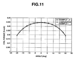
- a Nd-Fe-B sintered magnetizable block (N48M by Shin-Etsu Chemical Co., Ltd.) was machined into rectangular prisms of 20.2 mm x 12.4 mm x 6 mm. Two pieces were arranged in a straight serial contiguous array and adhesively attached to a yoke of carbon steel having a thickness of 5 mm. They were magnetized in a thickness direction by means of a magnetizer so that N and S poles of serially arranged magnet pieces alternated along the yoke, completing a VCM as shown in FIGS. 5A and 5B . The assembly process was otherwise the same as in Example 1. The torque of VCM was measured with the results shown in FIG. 11 .
- a magnetic circuit was constructed as in Example 1 except that a magnetizable block was machined into an arcuate piece of R29 x R16 x 6 mm x 60° (see FIG. 3 ).
- a VCM as shown in FIG. 3 was constructed and measured for torque, with the results shown in FIG. 11 .
- FIG. 10 illustrates a coil torque measuring system which includes a drive motor, a test shaft, a drive belt for operatively connecting the drive motor and the shaft, and a torque converter associated with the shaft.
- a VCM coil is mounted on the test shaft.
- the drive motor is operated to rotate the VCM coil while the torque is measured by the torque converter.
- the results are plotted in FIG. 11 .
Landscapes
- Engineering & Computer Science (AREA)
- Power Engineering (AREA)
- Reciprocating, Oscillating Or Vibrating Motors (AREA)
- Moving Of Heads (AREA)
Abstract
Description
- This invention relates to voice coil motors for head positioning in magnetic disk units, and magnetic circuits for use therein.
- In general, a hard disk unit includes a medium having a magnetic recording film deposited thereon, a spindle motor for rotating the medium at a predetermined rotational speed, a magnetic head for writing and reading information data, a voice coil motor (VCM) for driving the magnetic head, a controller and the like. The recent drastic price competition among manufacturers imposes a demand for further cost reduction on voice coil motors as well.
- Referring to
FIG. 1 , avoice coil motor 10 includesmagnetic material yokes JP-A 2004-23969 upper yoke 1 is omitted inFIG. 1 for simplicity of illustration. Theyokes magnetic material posts 5 such thatmagnets 2 face each other to define a space therebetween. A movingcoil 3 on anarm 4 is located in the space betweenmagnets 2. Thevoice coil motor 10 has a function of positioning a magnetic head. Aftermagnets 2 are disposed onyokes 1, they are magnetized so as to produce alternate magnetic poles in the order of N and S. - The shape of magnets is generally determined depending on the required performance of a voice coil motor. Referring to
FIG. 2 , amagnetic disk unit 20 is illustrated which includes a generallyrectangular housing 22 for receiving a magnetic disk 21. Thedisk unit 20 further includes apivot 23, anarm 24, amagnetic head actuator 25, and asuspension 26. Thevoice coil motor 10 is typically disposed at one corner ofhousing 22. To comply with this geometry, theyoke 1 is configured to (1) a triangular shape, typically right-angled triangular shape, includingside portions rectangular housing 22, anapex 12 defined byside portions bottom 13 opposed toapex 12, (2) a frusto-triangular shape in which the apex of a triangle is truncated or rounded, or (3) an arcuate, crescent or semi-circular ring shape in which the bottom of a triangle at its center is recessed or cut-off in a semi-circular, triangular or apex-rounded triangular form. The magnet is also configured in conformity to theyoke 1, specifically to an arcuate, truncated arcuate or truncated inverse-V shape as illustrated inFIG. 3 . - To form a magnet of an arcuate or similar shape, a mold of a corresponding shape must be prepared and worked such as by shaping, cutting, grinding or otherwise machining, which operation is expensive and less productive. In the event a magnet of an arcuate or similar shape is used, it is difficult to secure the magnet to the yoke at the registered position. A problem arises particularly in a compact magnetic disk unit because the accuracy of magnet registration has a substantial influence on the torque.
- A preferred embodiment of the invention is a magnetic circuit for a voice coil motor which may offer one or more advantages such as more accurate positioning of a magnetic head, minimized torque variation, and highly effective magnet production; and a voice coil motor.
- It has been found that when the magnet used in a voice coil motor is formed to a rectangular prism or parallelepiped prism shape, it is possible to achieve advantages such as minimized torque variation and more accurate positioning of a magnetic head. The invention is predicated on this finding.
- The invention provides a magnetic circuit and a voice coil motor as defined below.
- [1] A magnetic circuit for a voice coil motor, comprising a magnetic material yoke and a magnet of rectangular prism or parallelepiped prism shape disposed thereon.
- [2] A magnetic circuit for a voice coil motor, comprising a magnetic material yoke and two magnet pieces of rectangular prism or parallelepiped prism shape which are serially arranged thereon so that the magnet pieces produce alternate magnetic poles while their end faces are in abutment or spaced apart.
- [3] A magnetic circuit for a voice coil motor, comprising a pair of opposed magnetic material yokes, and a magnet disposed on at least one of the pair of yokes so that the magnet faces the other yoke, said magnet being a single magnet piece of rectangular prism or parallelepiped prism shape.
- [4] The magnetic circuit of [3], wherein a magnet is disposed on each of the pair of yokes so that the magnets face each other, each said magnet being a single magnet piece of rectangular prism or parallelepiped prism shape.
- [5] A magnetic circuit for a voice coil motor, comprising a pair of opposed magnetic material yokes, and a magnet disposed on at least one of the pair of yokes so that the magnet faces the other yoke, wherein said magnet consists of two magnet pieces of rectangular prism or parallelepiped prism shape, which are serially arranged on the yoke so that the magnet pieces produce alternate magnetic poles while their end faces are in abutment or spaced apart.
- [6] The magnetic circuit of [5], wherein a magnet is disposed on each of the pair of yokes so that the magnets face each other, and each said magnet consists of two magnet pieces of rectangular prism or parallelepiped prism shape, which are serially arranged on the yoke so that the magnet pieces produce alternate magnetic poles while their end faces are in abutment or spaced apart.
- [7] A voice coil motor comprising a pair of opposed magnetic material yokes, a magnet disposed on at least one of the pair of yokes so that the magnet faces the other yoke, and a moving coil located between the magnet and the other yoke, wherein said magnet is a single magnet piece of rectangular prism or parallelepiped prism shape.
- [8] The voice coil motor of [7], wherein a magnet is disposed on each of the pair of yokes so that the magnets face each other, and each said magnet is a single magnet piece of rectangular prism or parallelepiped prism shape. The moving coil is inserted into a space between the magnets each of which is disposed on each of the pair of yokes.
- [9] A voice coil motor comprising a pair of opposed magnetic material yokes, a magnet disposed on at least one of the pair of yokes so that the magnet faces the other yoke, and a moving coil located between the magnet and the other yoke, wherein said magnet consists of two magnet pieces of rectangular prism or parallelepiped prism shape, which are serially arranged on the yoke so that the magnet pieces produce alternate magnetic poles while their end faces are in abutment or spaced apart.
- [10] The voice coil motor of [9], wherein a magnet is disposed on each of the pair of yokes so that the magnets face each other, and each said magnet consists of two magnet pieces of rectangular prism or parallelepiped prism shape, which are serially arranged on the yoke so that the magnet pieces produce alternate magnetic poles while their end faces are in abutment or spaced apart. The moving coil is inserted into a space between the magnets each of which is disposed on each of the pair of yokes.
- Combination of a magnet of rectangular prism or parallelepiped prism shape with a yoke and a coil of proper shape may provide a magnetic circuit which may facilitate positioning and holding of the coil. The voice coil motor may be more accurate in positioning the magnetic head.
-
-
FIG. 1 is an exploded perspective view of a voice coil motor (VCM). -
FIG. 2 is a plan view of a magnetic disk unit. -
FIG. 3 is a schematic plan view of a prior art VCM. -
FIG. 4 schematically illustrates a VCM according to one embodiment of the invention,FIG. 4A being a plan view (taken along lines I-I inFIG. 4B) and FIG. 4B being an elevational view. -
FIG. 5 schematically illustrates a VCM according to another embodiment of the invention,FIG. 5A being a plan view (taken along lines II-II inFIG. 5B) and FIG. 5B being an elevational view. -
FIG. 6 schematically illustrates a VCM according to a further embodiment of the invention,FIG. 6A being a plan view (taken along lines III-III inFIG. 6B) and FIG. 6B being an elevational view. -
FIG. 7 schematically illustrates a VCM according to a still further embodiment of the invention,FIG. 7A being a plan view (taken along lines IV-IV inFIG. 7B) and FIG. 7B being an elevational view. -
FIG. 8 schematically illustrates a VCM according to a yet further embodiment of the invention,FIG. 8A being a plan view (taken along lines V-V inFIG. 8B) and FIG. 8B being an elevational view. -
FIG. 9 schematically illustrates a VCM according to a still further embodiment of the invention,FIG. 9A being a plan view (taken along lines VI-VI inFIG. 9B) and FIG. 9B being an elevational view. -
FIG. 10 schematically illustrates a coil torque measuring system. -
FIG. 11 is a graph showing the coil torque of VCM as a function of angle. - In the following description, like reference characters designate like or corresponding parts throughout the several views. It is also understood that terms such as "top," "bottom," "lateral" and the like are words of convenience and used as seen looking at a figure and are not to be construed as limiting terms.
- Referring to
FIG. 4 , a voice coil motor (VCM) according to one embodiment of the invention is illustrated. The magnetic circuit of the invention is composed essentially of magnetic material yokes and magnets. As shown inFIGS. 4A and 4B , the VCM includes a pair ofyokes 1b having magnets yokes posts magnets coil 3 is inserted into the space betweenmagnets - The VCM is characterized in that one magnet of rectangular prism or parallelepiped prism shape is disposed on each yoke; or two magnet pieces of rectangular prism or parallelepiped prism shape are serially arranged on each yoke so that the magnet pieces produce alternate magnetic poles.
- The yoke has a shape that fits in the magnetic disk unit and is disposed at one corner of a rectangular shaped housing for receiving a magnetic disk. The yoke is generally configured to a triangular shape, a frusto-triangular shape in which the apex of a triangle is truncated or rounded, or an arcuate, crescent or semi-circular ring shape in which the bottom of a triangle at its center is recessed or cut-off in a semi-circular, triangular or apex-rounded triangular form. The yoke is made of a magnetic material such as silicon steel or carbon steel and usually provided at lateral ends with holes through which posts or bolts are fitted to couple magnetic circuits together.
- A magnet is registered and adhesively attached onto the yoke. According to the invention, the magnet has a rectangular prism or parallelepiped prism shape, which facilitates registration of the magnet relative to the yoke. By contrast, when a magnet has an arcuate or curved shape commonly employed in the prior art, registration of the magnet relative to the yoke is less easy, and any misregistration leads to a problem of torque variations.
- The disposition of a magnet on a yoke is described. When one magnet piece is used per yoke, as shown in
FIG. 4A ,magnet piece 2 is preferably disposed onyoke 1 such that the longitudinal direction ofmagnet piece 2 is parallel or substantially parallel to a bottom 13 of yoke 1 (i.e., a straight line connecting the lower ends of twooblique sides 11, 11). When two magnet pieces are used per yoke, as shown inFIGS. 5A and6A , twomagnet pieces magnet pieces 2 is parallel to bottom 13 ofyoke 1. It is understood that a magnet piece of rectangular or parallelepiped prism shape has a pair of major surfaces, a pair of end faces, and a pair of side faces.FIG. 5A and 5B illustrates one embodiment wherein two magnet pieces are arranged side by side with their end faces in abutment.FIG. 6A and 6B illustrates another embodiment wherein two magnet pieces are arranged so as to leave agap 7 between their end faces. Except for the arrangement of magnet pieces, the construction of these embodiments is the same as in the magnetic circuit and VCM ofFIGS. 4A and 4B . - Although
magnets yokes FIGS. 4 to 6 , it is also acceptable that as shown inFIGS. 7 to 9 , onemagnet 2a (consisting of a single piece or two abutted or spaced pieces) is disposed on only oneyoke 1a, no magnet is disposed on theother yoke 1b, and theother yoke 1b faces themagnet 2a. In the latter case, the movingcoil 3 is inserted betweenmagnet 2a and theother yoke 1b. Specifically,FIG. 7 illustrates one embodiment wherein amonolithic magnet 2a is disposed on only oneyoke 1a;FIG. 8 illustrates another embodiment wherein twomagnet pieces yoke 1a;FIG. 9 illustrates a further embodiment wherein twomagnet pieces yoke 1a so as to leave agap 7 therebetween. - The number of magnet pieces on each yoke is one or two as mentioned above. In the case of one magnet piece, it is magnetized so as to produce alternate magnetic poles in a planar direction. In the case of two magnet pieces, each piece is magnetized in a thickness direction to produce N and S poles on their surface, and two pieces are arranged in series so that N and S poles alternate in a plan view. The arrangement of two magnet pieces may be adjusted such that the distance between the magnet pieces may range from zero to a suitable value, depending on the deflection range or amplitude of the moving coil.
- For attachment of magnets, heat resistant adhesives such as epoxy resins or acrylic resins are preferably used. In view of the heat release within the hard disk unit, the magnet may be attached to the yoke by the attractive force of the magnet without resorting to the adhesive.
- The magnet used herein may have a rectangular prism or parallelepiped prism shape as mentioned above, with the rectangular prism shape being preferred from the working aspect. Ordinary magnets used in the industry include sintered magnets prepared from magnetizable raw materials by melting, grinding, molding and sintering, and bonded magnets prepared by melting, grinding, and resin-aided molding. This is also true in the invention. When a rectangular mold is used in the molding step, the molded part may be easily machined to the desired hexahedral structure. Then the yield of magnet working is improved. Magnets may be worked into a rectangular shape using a peripheral milling edge or wire saw.
- As described above, either sintered magnets or bonded magnets may be used in the practice of the invention. They may be ferrite, alnico or rare earth magnets. In the case of rare earth magnets which are susceptible to oxidation, a plating of metal such as Ni or Cu or a coating of antioxidant is recommended.
- In the embodiments of
FIGS. 4 to 6 wherein magnets are disposed on two yokes, respectively, the magnetic circuits each consisting of a yoke and a magnet attached thereto are assembled so that the magnets face each other while they are spaced apart by magnetic material posts, and an arm having a moving coil wound thereon is inserted into the space defined between the magnetic circuits, constructing a VCM. In the embodiments ofFIGS. 7 to 9 wherein a magnet is disposed on one yoke, but not on the other yoke, the components are assembled so that the magnet faces the other yoke, and an arm having a moving coil wound thereon is inserted into the space defined between the magnet and the other yoke, constructing a VCM. The magnetic circuits to be opposed should have the same properties. The resulting VCM operates in accordance with Fleming's rule to drive the moving coil for imparting thrust to the actuator. - Examples of the invention are given below by way of illustration and not by way of limitation.
- A Nd-Fe-B sintered magnetizable block (N48M by Shin-Etsu Chemical Co., Ltd.) was machined into a rectangular prism of 40.4 mm x 12.4 mm x 6 mm. It was adhesively attached to a yoke of carbon steel having a thickness of 5 mm and then magnetized to produce N and S poles by means of a magnetizer, constructing a magnetic circuit. The magnet could be attached to the yoke at its center, ensuring ease of registration.
- Two yokes were fixedly coupled by posts of the same magnetic material as the yokes to define a space of 10 mm between the magnets. An arm having a moving coil of copper wire wound thereon was inserted into the space, constructing a VCM as shown in
FIGS. 4A and 4B . The torque of VCM was measured with the results shown inFIG. 11 . - A Nd-Fe-B sintered magnetizable block (N48M by Shin-Etsu Chemical Co., Ltd.) was machined into rectangular prisms of 20.2 mm x 12.4 mm x 6 mm. Two pieces were arranged in a straight serial contiguous array and adhesively attached to a yoke of carbon steel having a thickness of 5 mm. They were magnetized in a thickness direction by means of a magnetizer so that N and S poles of serially arranged magnet pieces alternated along the yoke, completing a VCM as shown in
FIGS. 5A and 5B . The assembly process was otherwise the same as in Example 1. The torque of VCM was measured with the results shown inFIG. 11 . - A magnetic circuit was constructed as in Example 1 except that a magnetizable block was machined into an arcuate piece of R29 x R16 x 6 mm x 60° (see
FIG. 3 ). A VCM as shown inFIG. 3 was constructed and measured for torque, with the results shown inFIG. 11 . - In the foregoing Examples and Comparative Example, the torque of VCM was measured by the following method.
FIG. 10 illustrates a coil torque measuring system which includes a drive motor, a test shaft, a drive belt for operatively connecting the drive motor and the shaft, and a torque converter associated with the shaft. A VCM coil is mounted on the test shaft. The drive motor is operated to rotate the VCM coil while the torque is measured by the torque converter. The results are plotted inFIG. 11 . - As seen from
FIG. 11 , a necessary torque is available when prism-shaped magnet pieces which can be efficiently produced at a relatively low cost are used.
Claims (10)
- A magnetic circuit for a voice coil motor, comprising a magnetic material yoke and a magnet of rectangular prism or parallelepiped prism shape disposed thereon.
- A magnetic circuit for a voice coil motor, comprising a magnetic material yoke and two magnet pieces of rectangular prism or parallelepiped prism shape which are serially arranged thereon so that the magnet pieces produce alternate magnetic poles while their end faces are in abutment or spaced apart.
- A magnetic circuit for a voice coil motor, comprising
a pair of opposed magnetic material yokes, and
a magnet disposed.on at least one of the pair of yokes so that the magnet faces the other yoke,
said magnet being a single magnet piece of rectangular prism or parallelepiped prism shape. - The magnetic circuit of claim 3, wherein a magnet is disposed on each of the pair of yokes so that the magnets face each other,
each said magnet being a single magnet piece of rectangular prism or parallelepiped prism shape. - A magnetic circuit for a voice coil motor, comprising
a pair of opposed magnetic material yokes, and
a magnet disposed on at least one of the pair of yokes so that the magnet faces the other yoke,
said magnet consisting of two magnet pieces of rectangular prism or parallelepiped prism shape, which are serially arranged on the yoke so that the magnet pieces produce alternate magnetic poles while their end faces are in abutment or spaced apart. - The magnetic circuit of claim 5, wherein a magnet is disposed on each of the pair of yokes so that the magnets face each other,
each said magnet consisting of two magnet pieces of rectangular prism or parallelepiped prism shape, which are serially arranged on the yoke so that the magnet pieces produce alternate magnetic poles while their end faces are in abutment or spaced apart. - A voice coil motor comprising
a pair of opposed magnetic material yokes,
a magnet disposed on at least one of the pair of yokes so that the magnet faces the other yoke, and
a moving coil located between the magnet and the other yoke, wherein
said magnet is a single magnet piece of rectangular prism or parallelepiped prism shape. - The voice coil motor of claim 7, wherein a magnet is disposed on each of the pair of yokes so that the magnets face each other, and
each said magnet is a single magnet piece of rectangular prism or parallelepiped prism shape. - A voice coil motor comprising
a pair of opposed magnetic material yokes,
a magnet disposed on at least one of the pair of yokes so that the magnet faces the other yoke, and
a moving coil located between the magnet and the other yoke, wherein
said magnet consists of two magnet pieces of rectangular prism or parallelepiped prism shape, which are serially arranged on the yoke so that the magnet pieces produce alternate magnetic poles while their end faces are in abutment or spaced apart. - The voice coil motor of claim 9, wherein a magnet is disposed on each of the pair of yokes so that the magnets face each other, and
each said magnet consists of two magnet pieces of rectangular prism or parallelepiped prism shape, which are serially arranged on the yoke so that the magnet pieces produce alternate magnetic poles while their end faces are in abutment or spaced apart.
Applications Claiming Priority (1)
| Application Number | Priority Date | Filing Date | Title |
|---|---|---|---|
| JP2007072789 | 2007-03-20 |
Publications (2)
| Publication Number | Publication Date |
|---|---|
| EP1973107A1 true EP1973107A1 (en) | 2008-09-24 |
| EP1973107B1 EP1973107B1 (en) | 2011-07-13 |
Family
ID=39529861
Family Applications (1)
| Application Number | Title | Priority Date | Filing Date |
|---|---|---|---|
| EP08250967A Not-in-force EP1973107B1 (en) | 2007-03-20 | 2008-03-19 | Voice coil motor and magnetic circuit therefor |
Country Status (7)
| Country | Link |
|---|---|
| US (2) | US8194358B2 (en) |
| EP (1) | EP1973107B1 (en) |
| JP (2) | JP5035552B2 (en) |
| KR (1) | KR101048956B1 (en) |
| CN (1) | CN101369770B (en) |
| MY (1) | MY150441A (en) |
| TW (1) | TWI375382B (en) |
Families Citing this family (9)
| Publication number | Priority date | Publication date | Assignee | Title |
|---|---|---|---|---|
| JP5035552B2 (en) | 2007-03-20 | 2012-09-26 | 信越化学工業株式会社 | Magnetic circuit for voice coil motor and voice coil motor |
| JP5035553B2 (en) * | 2007-03-20 | 2012-09-26 | 信越化学工業株式会社 | Magnetic circuit for voice coil motor and voice coil motor |
| JP5308457B2 (en) * | 2009-01-23 | 2013-10-09 | 株式会社ケンコー・トキナー | Voice coil motor for driving correction lens, camera shake correction device, interchangeable lens and optical device |
| MY168007A (en) | 2012-04-13 | 2018-10-11 | Sony Corp | Wireless communication device, communication system, and communication method |
| JP6146148B2 (en) * | 2013-06-07 | 2017-06-14 | 日立金属株式会社 | Voice coil motor and magnet used for the voice coil motor |
| US10867638B2 (en) * | 2019-01-30 | 2020-12-15 | Seagate Technology Llc | Ultrasonic welding for sealing electronic devices |
| US10916269B2 (en) * | 2019-02-19 | 2021-02-09 | Western Digital Technologies, Inc. | Magnet for motor of magnetic storage device |
| WO2024158016A1 (en) * | 2023-01-24 | 2024-08-02 | Tdk株式会社 | Voice coil actuator |
| US20250079101A1 (en) * | 2023-08-31 | 2025-03-06 | Siemens Industry, Inc. | Magnetic switch for hybrid circuit breaker applications |
Citations (3)
| Publication number | Priority date | Publication date | Assignee | Title |
|---|---|---|---|---|
| US5122702A (en) * | 1990-06-26 | 1992-06-16 | Nec Corporation | Rotary voice coil motor with a flat coil |
| US6043957A (en) * | 1997-03-21 | 2000-03-28 | Nec Corporation | Head positioning mechanism for magnetic disk device provided with micro tracking actuator using magnetic force and drive control method therefor |
| JP2004023969A (en) | 2002-06-20 | 2004-01-22 | Sumitomo Special Metals Co Ltd | Voice coil motor and magnetic disk unit using it |
Family Cites Families (52)
| Publication number | Priority date | Publication date | Assignee | Title |
|---|---|---|---|---|
| DE2742050A1 (en) * | 1977-09-19 | 1979-03-29 | Papst Motoren Kg | MULTI-PHASE LINEAR MOTOR |
| JPS57103171A (en) | 1980-12-18 | 1982-06-26 | Fujitsu Ltd | Actuator for magnetic recorder |
| US4396966A (en) * | 1980-12-31 | 1983-08-02 | International Business Machines Corporation | Low mass actuator system for magnetic recording disks with half strength end poles |
| US4415941A (en) * | 1981-06-29 | 1983-11-15 | Atasi Corporation | Linear actuator for memory storage device |
| US4506307A (en) * | 1981-11-10 | 1985-03-19 | Ibm | Magnetic head slider and actuator assembly |
| US4439699A (en) * | 1982-01-18 | 1984-03-27 | International Business Machines Corporation | Linear moving coil actuator |
| USD281321S (en) * | 1982-11-24 | 1985-11-12 | Maxtor Corporation | Winchester disc drive |
| US4652779A (en) * | 1984-10-30 | 1987-03-24 | Magnetic Peripherals Inc. | Center pole for rotary actuator coil with lowered inductance |
| US5956213A (en) * | 1988-01-25 | 1999-09-21 | Seagate Technology, Inc. | Latch mechanism for disk drive using magnetic field of actuator magnets |
| JPH02103783U (en) | 1989-01-27 | 1990-08-17 | ||
| FR2654271B1 (en) * | 1989-11-06 | 1992-01-24 | Moving Magnet Tech | ANGULAR SINGLE PHASE ELECTROMAGNETIC ACTUATOR. |
| JPH03173343A (en) * | 1989-11-29 | 1991-07-26 | Sony Corp | Moving coil actuator |
| US5808838A (en) * | 1990-02-09 | 1998-09-15 | Seagate Technologies, Inc. | Miniature head disc drive system voice coil with single coil and dual stationary magnets |
| JP2696417B2 (en) * | 1990-05-18 | 1998-01-14 | 住友特殊金属株式会社 | Bipolar magnetizer |
| US5315466A (en) * | 1991-03-06 | 1994-05-24 | Fuji Electric Co., Ltd. | Magnetic disk unit having reduced profile and/or faster seek speed |
| JPH04368674A (en) * | 1991-06-17 | 1992-12-21 | Nec Ibaraki Ltd | Magnetic circuit for magnetic head driving device |
| JP2544063B2 (en) * | 1992-06-22 | 1996-10-16 | 株式会社東芝 | Carriage locking method for magnetic disk device and magnetic disk device |
| JPH06178523A (en) | 1992-12-03 | 1994-06-24 | Fujitsu Ltd | Magnetic circuit for voice coil motor |
| US5581422A (en) * | 1993-02-09 | 1996-12-03 | Hitachi Metals, Ltd. | Actuator with moveable coil and recording apparatus |
| JP2522179B2 (en) * | 1993-08-10 | 1996-08-07 | 日本電気株式会社 | Magnetic head drive |
| JPH07170712A (en) * | 1993-12-15 | 1995-07-04 | Sumitomo Special Metals Co Ltd | Actuator |
| US5659215A (en) * | 1994-05-19 | 1997-08-19 | Seagate Technology, Inc. | Small form factor actuator for improved functionality and linearity |
| KR100263045B1 (en) * | 1994-07-07 | 2000-08-01 | 윤종용 | Method and device for fastening a voice coil motor of a hard disk |
| DE69504358T2 (en) * | 1994-08-02 | 1999-01-07 | Seagate Technology, Inc., Scotts Valley, Calif. | DISK DRIVE WITH EMBEDDED VOICE COIL MAGNET PLATES |
| JP3476100B2 (en) * | 1995-01-06 | 2003-12-10 | 日立金属株式会社 | Arm assembly and voice coil motor |
| JPH08249846A (en) * | 1995-03-13 | 1996-09-27 | Fujitsu Ltd | Rotary actuator for disk device |
| JP3343805B2 (en) | 1995-08-15 | 2002-11-11 | 富士通株式会社 | Disk unit |
| WO1997020310A1 (en) * | 1995-11-28 | 1997-06-05 | Micropolis Corporation | Twin coil positioning device for use in a family of hard disk drives having interchangeable magnet components |
| US5621591A (en) * | 1996-04-05 | 1997-04-15 | Seagate Technology, Inc. | Dual coil voice coil motor |
| JP3434967B2 (en) * | 1996-04-12 | 2003-08-11 | 富士通株式会社 | Actuator structure and recording / reproducing device using the same |
| KR19990008845A (en) * | 1997-07-04 | 1999-02-05 | 윤종용 | VCM damper on hard disk drive |
| US5999372A (en) * | 1997-12-30 | 1999-12-07 | Seagate Technology, Inc. | Actuator arm with streamlined leading edge to reduce air turbulence |
| US6115215A (en) * | 1998-02-24 | 2000-09-05 | Seagate Technology, Inc. | Balanced actuator which accesses separate disc assemblies |
| JP2000040314A (en) * | 1998-07-24 | 2000-02-08 | Alps Electric Co Ltd | Head transfer device |
| US6175469B1 (en) * | 1998-12-04 | 2001-01-16 | Seagate Technology, Inc. | Disc drive magnet housing electro mechanical resonance dampening system |
| US6268984B1 (en) * | 1999-01-22 | 2001-07-31 | Seagate Technology Llc | Magnet configuration for head-level microactuator |
| US6252744B1 (en) * | 1999-03-01 | 2001-06-26 | Seagate Technology Llc | Voice-coil integrated non-contacting magnetic latch for a disc drive actuator assembly |
| JP2001035103A (en) * | 1999-07-15 | 2001-02-09 | Fujitsu Ltd | Disk unit |
| MY127853A (en) * | 1999-09-08 | 2006-12-29 | Shinetsu Chemical Co | Yoke compartment of voice coil motor for hard disk drive and voice coil motor using said yoke component |
| US6549380B2 (en) * | 2000-04-17 | 2003-04-15 | Seagate Technology Llc | Data handling system with flux-directing voice coil motor |
| JP4554777B2 (en) * | 2000-07-17 | 2010-09-29 | パナソニック株式会社 | Actuator for disk device |
| US6608732B2 (en) * | 2000-07-26 | 2003-08-19 | Seagate Technology Llc | Damper for disc drive voice coil motor |
| US6606223B2 (en) * | 2000-09-27 | 2003-08-12 | Seagate Technology Llc | Voice coil motor dummy magnet |
| JP2002136092A (en) * | 2000-10-27 | 2002-05-10 | Matsushita Electric Ind Co Ltd | Voice coil motor |
| JP3464988B2 (en) * | 2001-09-21 | 2003-11-10 | 株式会社東芝 | Disk device, yoke incorporated in disk device, and method of manufacturing yoke |
| JP3705214B2 (en) * | 2002-01-28 | 2005-10-12 | 松下電器産業株式会社 | Disk unit |
| JP2005243177A (en) * | 2004-02-27 | 2005-09-08 | Fujitsu Ltd | Magnetic disk unit |
| KR100714101B1 (en) * | 2004-12-08 | 2007-05-02 | 한국전자통신연구원 | Small size optical/magnetic head actuator with a pivot hinge and a halbach array magnet |
| JP2007035184A (en) * | 2005-07-28 | 2007-02-08 | Fujitsu Ltd | Magnetic disk unit |
| JP5035553B2 (en) * | 2007-03-20 | 2012-09-26 | 信越化学工業株式会社 | Magnetic circuit for voice coil motor and voice coil motor |
| JP5035552B2 (en) | 2007-03-20 | 2012-09-26 | 信越化学工業株式会社 | Magnetic circuit for voice coil motor and voice coil motor |
| CN101345069B (en) * | 2007-07-09 | 2011-09-14 | 新科实业有限公司 | Voice coil motor and disk drive unit having the same |
-
2008
- 2008-03-14 JP JP2008065234A patent/JP5035552B2/en not_active Expired - Fee Related
- 2008-03-17 MY MYPI20080711 patent/MY150441A/en unknown
- 2008-03-19 US US12/051,700 patent/US8194358B2/en not_active Expired - Fee Related
- 2008-03-19 TW TW097109665A patent/TWI375382B/en not_active IP Right Cessation
- 2008-03-19 EP EP08250967A patent/EP1973107B1/en not_active Not-in-force
- 2008-03-19 KR KR1020080025152A patent/KR101048956B1/en not_active Expired - Fee Related
- 2008-03-20 CN CN200810168686XA patent/CN101369770B/en not_active Expired - Fee Related
-
2011
- 2011-12-19 JP JP2011277116A patent/JP5035578B2/en not_active Expired - Fee Related
-
2012
- 2012-01-12 US US13/348,893 patent/US20120113548A1/en not_active Abandoned
Patent Citations (4)
| Publication number | Priority date | Publication date | Assignee | Title |
|---|---|---|---|---|
| US5122702A (en) * | 1990-06-26 | 1992-06-16 | Nec Corporation | Rotary voice coil motor with a flat coil |
| US6043957A (en) * | 1997-03-21 | 2000-03-28 | Nec Corporation | Head positioning mechanism for magnetic disk device provided with micro tracking actuator using magnetic force and drive control method therefor |
| US6342987B1 (en) * | 1997-03-21 | 2002-01-29 | Nec Corporation | Head positioning mechanism for magnetic disk device provided with micro tracking actuator using magnetic force drive control method therefor |
| JP2004023969A (en) | 2002-06-20 | 2004-01-22 | Sumitomo Special Metals Co Ltd | Voice coil motor and magnetic disk unit using it |
Also Published As
| Publication number | Publication date |
|---|---|
| MY150441A (en) | 2014-01-30 |
| KR20080085743A (en) | 2008-09-24 |
| US8194358B2 (en) | 2012-06-05 |
| CN101369770A (en) | 2009-02-18 |
| TWI375382B (en) | 2012-10-21 |
| CN101369770B (en) | 2013-04-17 |
| US20120113548A1 (en) | 2012-05-10 |
| TW200845540A (en) | 2008-11-16 |
| KR101048956B1 (en) | 2011-07-12 |
| EP1973107B1 (en) | 2011-07-13 |
| JP2008263769A (en) | 2008-10-30 |
| JP2012100527A (en) | 2012-05-24 |
| US20080231997A1 (en) | 2008-09-25 |
| JP5035578B2 (en) | 2012-09-26 |
| JP5035552B2 (en) | 2012-09-26 |
Similar Documents
| Publication | Publication Date | Title |
|---|---|---|
| EP1973107B1 (en) | Voice coil motor and magnetic circuit therefor | |
| JP2880280B2 (en) | Single phase electromagnetic angle actuator | |
| US7675202B1 (en) | Isotropic ring magnet linear voice coil motor | |
| EP1973105B1 (en) | Voice coil motor and magnetic circuit therefor | |
| US6157099A (en) | Specially oriented material and magnetization of permanent magnets | |
| US20220139420A1 (en) | Hard Disk Drive with Composite Permanent Magnet | |
| US7616532B2 (en) | Optical disc drive | |
| JPH0698489A (en) | Rotor for servo motor | |
| JP4583713B2 (en) | Magnetic head actuator | |
| JP4583714B2 (en) | Magnetic head actuator | |
| JPS5935558A (en) | Manufacturing method of motor core | |
| US20070223325A1 (en) | Optical disk apparatus | |
| JPH11260011A (en) | Head support mechanism | |
| JP4232040B2 (en) | Magnetic head actuator and magnetic disk device using the same | |
| JPH0545106Y2 (en) | ||
| JPS6237055A (en) | Manufacture of linear pulse motor | |
| JPS62207167A (en) | Small-sized linear pulse motor | |
| JP2003051107A (en) | Disc-shaped recording medium, rotor structure, and information recording / reproducing apparatus using these | |
| JPS62114464A (en) | Linear pulse motor | |
| JPH011465A (en) | Small linear pulse motor | |
| JPH0510750B2 (en) | ||
| JPS62233059A (en) | Miniature linear pulse motor | |
| JPH01177855A (en) | Small-sized linear pulse motor | |
| JP2003121202A (en) | MnAl magnetic scale for encoder | |
| JPH07143720A (en) | Arm assembly and voice-coil motor |
Legal Events
| Date | Code | Title | Description |
|---|---|---|---|
| PUAI | Public reference made under article 153(3) epc to a published international application that has entered the european phase |
Free format text: ORIGINAL CODE: 0009012 |
|
| AK | Designated contracting states |
Kind code of ref document: A1 Designated state(s): AT BE BG CH CY CZ DE DK EE ES FI FR GB GR HR HU IE IS IT LI LT LU LV MC MT NL NO PL PT RO SE SI SK TR |
|
| AX | Request for extension of the european patent |
Extension state: AL BA MK RS |
|
| 17P | Request for examination filed |
Effective date: 20081229 |
|
| 17Q | First examination report despatched |
Effective date: 20090210 |
|
| AKX | Designation fees paid |
Designated state(s): DE FR GB |
|
| GRAP | Despatch of communication of intention to grant a patent |
Free format text: ORIGINAL CODE: EPIDOSNIGR1 |
|
| GRAS | Grant fee paid |
Free format text: ORIGINAL CODE: EPIDOSNIGR3 |
|
| GRAA | (expected) grant |
Free format text: ORIGINAL CODE: 0009210 |
|
| AK | Designated contracting states |
Kind code of ref document: B1 Designated state(s): DE FR GB |
|
| REG | Reference to a national code |
Ref country code: GB Ref legal event code: FG4D |
|
| REG | Reference to a national code |
Ref country code: DE Ref legal event code: R096 Ref document number: 602008008221 Country of ref document: DE Effective date: 20110908 |
|
| PLBE | No opposition filed within time limit |
Free format text: ORIGINAL CODE: 0009261 |
|
| STAA | Information on the status of an ep patent application or granted ep patent |
Free format text: STATUS: NO OPPOSITION FILED WITHIN TIME LIMIT |
|
| 26N | No opposition filed |
Effective date: 20120416 |
|
| REG | Reference to a national code |
Ref country code: DE Ref legal event code: R097 Ref document number: 602008008221 Country of ref document: DE Effective date: 20120416 |
|
| REG | Reference to a national code |
Ref country code: FR Ref legal event code: PLFP Year of fee payment: 9 |
|
| PGFP | Annual fee paid to national office [announced via postgrant information from national office to epo] |
Ref country code: DE Payment date: 20160315 Year of fee payment: 9 |
|
| PGFP | Annual fee paid to national office [announced via postgrant information from national office to epo] |
Ref country code: FR Payment date: 20160208 Year of fee payment: 9 Ref country code: GB Payment date: 20160316 Year of fee payment: 9 |
|
| REG | Reference to a national code |
Ref country code: DE Ref legal event code: R119 Ref document number: 602008008221 Country of ref document: DE |
|
| GBPC | Gb: european patent ceased through non-payment of renewal fee |
Effective date: 20170319 |
|
| REG | Reference to a national code |
Ref country code: FR Ref legal event code: ST Effective date: 20171130 |
|
| PG25 | Lapsed in a contracting state [announced via postgrant information from national office to epo] |
Ref country code: FR Free format text: LAPSE BECAUSE OF NON-PAYMENT OF DUE FEES Effective date: 20170331 Ref country code: DE Free format text: LAPSE BECAUSE OF NON-PAYMENT OF DUE FEES Effective date: 20171003 |
|
| PG25 | Lapsed in a contracting state [announced via postgrant information from national office to epo] |
Ref country code: GB Free format text: LAPSE BECAUSE OF NON-PAYMENT OF DUE FEES Effective date: 20170319 |