JP5035552B2 - Magnetic circuit for voice coil motor and voice coil motor - Google Patents
Magnetic circuit for voice coil motor and voice coil motor Download PDFInfo
- Publication number
- JP5035552B2 JP5035552B2 JP2008065234A JP2008065234A JP5035552B2 JP 5035552 B2 JP5035552 B2 JP 5035552B2 JP 2008065234 A JP2008065234 A JP 2008065234A JP 2008065234 A JP2008065234 A JP 2008065234A JP 5035552 B2 JP5035552 B2 JP 5035552B2
- Authority
- JP
- Japan
- Prior art keywords
- magnetic
- shape
- magnet
- voice coil
- yoke
- Prior art date
- Legal status (The legal status is an assumption and is not a legal conclusion. Google has not performed a legal analysis and makes no representation as to the accuracy of the status listed.)
- Expired - Fee Related
Links
Images


Classifications
-
- H—ELECTRICITY
- H02—GENERATION; CONVERSION OR DISTRIBUTION OF ELECTRIC POWER
- H02K—DYNAMO-ELECTRIC MACHINES
- H02K1/00—Details of the magnetic circuit
- H02K1/06—Details of the magnetic circuit characterised by the shape, form or construction
-
- G—PHYSICS
- G11—INFORMATION STORAGE
- G11B—INFORMATION STORAGE BASED ON RELATIVE MOVEMENT BETWEEN RECORD CARRIER AND TRANSDUCER
- G11B5/00—Recording by magnetisation or demagnetisation of a record carrier; Reproducing by magnetic means; Record carriers therefor
- G11B5/48—Disposition or mounting of heads or head supports relative to record carriers ; arrangements of heads, e.g. for scanning the record carrier to increase the relative speed
- G11B5/54—Disposition or mounting of heads or head supports relative to record carriers ; arrangements of heads, e.g. for scanning the record carrier to increase the relative speed with provision for moving the head into or out of its operative position or across tracks
- G11B5/55—Track change, selection or acquisition by displacement of the head
- G11B5/5521—Track change, selection or acquisition by displacement of the head across disk tracks
- G11B5/5569—Track change, selection or acquisition by displacement of the head across disk tracks details of specially adapted mobile parts, e.g. electromechanical control devices
-
- G—PHYSICS
- G11—INFORMATION STORAGE
- G11B—INFORMATION STORAGE BASED ON RELATIVE MOVEMENT BETWEEN RECORD CARRIER AND TRANSDUCER
- G11B21/00—Head arrangements not specific to the method of recording or reproducing
- G11B21/02—Driving or moving of heads
-
- H—ELECTRICITY
- H02—GENERATION; CONVERSION OR DISTRIBUTION OF ELECTRIC POWER
- H02K—DYNAMO-ELECTRIC MACHINES
- H02K33/00—Motors with reciprocating, oscillating or vibrating magnet, armature or coil system
- H02K33/18—Motors with reciprocating, oscillating or vibrating magnet, armature or coil system with coil systems moving upon intermittent or reversed energisation thereof by interaction with a fixed field system, e.g. permanent magnets
Landscapes
- Engineering & Computer Science (AREA)
- Power Engineering (AREA)
- Reciprocating, Oscillating Or Vibrating Motors (AREA)
- Moving Of Heads (AREA)
Description
本発明は、磁気ディスク装置のヘッド位置決めを行うボイスコイルモータにおける磁気回路及びボイスコイルモータに関するものである。 The present invention relates to a magnetic circuit and a voice coil motor in a voice coil motor for positioning a head of a magnetic disk device.
ハードディスクには、磁気記録膜を成膜したメディアとそのメディアを必要な回転数に回転させるスピンドルモータ、記録内容を読み書きする磁気ヘッドとそれを駆動するボイスコイルモータ(VCM)及び制御装置等が配置される。近年、メーカーの激しい価格競争により、ボイスコイルモータにも更なる低コストが要求されている。 The hard disk is equipped with a medium on which a magnetic recording film is formed, a spindle motor that rotates the medium to the required number of revolutions, a magnetic head that reads and writes recorded contents, a voice coil motor (VCM) that drives the head, and a control device. Is done. In recent years, due to fierce price competition among manufacturers, voice coil motors are also required to have lower costs.
図1に示す如く、ボイスコイルモータ10は、特開2004−23969号公報(特許文献1)に記載のように、磁性体ヨーク1,1に磁石(永久磁石)2をそれぞれ接着配置し(なお、図において、一方の磁性体ヨークに接着配置した磁石は図示を省略している)、上記両磁石2が互いに対向するようにヨーク1,1を配設すると共に、上記両磁石2間の空隙に可動コイル3を介在させたもので、磁気ヘッドを位置決めさせる機能を有している。なお、図中4は、アーム、5は柱状磁性体である。両磁石2は、ヨーク1上に配置された後、磁極がNSの交互になるように着磁されている。
As shown in FIG. 1, in the
ここで、磁石の形状は、ボイスコイルモータ特性に起因して形状が決められるのが通常である。
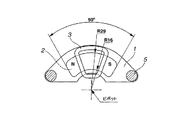
即ち、例えば図2に示すように、ボイスコイルモータ10は、通常、磁気ディスク装置20の磁気ディスク21を収容するための四角形状の収容体22の一隅部に配設されるが、ヨーク1も、これに対応し、四角形状の収容体22の一隅部を形成する互いに隣り合う壁面に対向する両側辺部11,11とこれら両側辺部11,11によって形成される頂部12に対向する底辺部13とを有する三角形状(特に直角三角形形状)、この三角形状の頂部が切り落とされ、或いは頂部が丸味を帯びた状態の三角形状、これら三角形の底辺部の中央部が半円状、三角形状、頂部が丸味を帯びた三角形状等に凹んだ乃至は切り欠かれた扇形状、三日月状乃至半円形リング状などの形状に形成される。なお、図2中、23はピボット回転軸、24はアーム、25は磁気ヘッドアクチュエータ、26はサスペンションである。そして、磁石も、図3に示したように、このヨーク1に相応した形状、つまり扇状、或いは円弧状乃至扁平逆V字状等の形状に形成される。
Here, the shape of the magnet is usually determined due to the voice coil motor characteristics.
That is, for example, as shown in FIG. 2, the
磁石をこのように扇形状等に形成するには、金型の作製及び加工(成形、切断、切削等)のコストが高く、生産性が高くない状態である。また、扇形状等の磁石形状を用いた場合には、ヨーク上において磁石を固定する場合、希望の位置に固定させることが難しく、特に小型化されている磁気ディスク装置において磁石の位置決め精度がトルクに与える影響が大きく問題が発生していた。 In order to form a magnet in a fan shape or the like in this way, the cost of manufacturing and processing a mold (molding, cutting, cutting, etc.) is high, and productivity is not high. In addition, when a magnet shape such as a fan shape is used, it is difficult to fix the magnet on the yoke, and it is difficult to fix the magnet at a desired position. The problem had a big impact on the problem.
本発明は、上記事情に鑑みなされたもので、磁気ヘッドの位置決め性が向上し、トルク変動が小さく、しかも磁石製造の生産性の高いボイスコイルモータ用磁気回路及びボイスコイルモータを提供することを目的とする。 The present invention has been made in view of the above circumstances, and provides a magnetic circuit for a voice coil motor and a voice coil motor with improved magnetic head positioning, small torque fluctuations, and high magnet manufacturing productivity. Objective.
本発明者らは、上記目的を達成するために鋭意研究を行ったところ、ボイスコイルモータに用いる磁石を直方体又は平行四辺形柱とした場合、磁気ヘッドの位置決めが向上し、トルク変動が小さいといった作用効果が得られることを知見し、本発明をなすに至ったものである。 The inventors of the present invention have conducted intensive research to achieve the above object. When the magnet used for the voice coil motor is a rectangular parallelepiped or a parallelogram pillar, the positioning of the magnetic head is improved and the torque fluctuation is small. The present inventors have found that an operational effect can be obtained and have come to make the present invention.
即ち、本発明は、下記ボイスコイルモータ用磁気回路及びボイスコイルモータを提供する。
請求項1
磁性体ヨーク上に磁石を配置してなるボイスコイルモータ用磁気回路において、磁性体ヨークが、三角形状、頂部が切り落とされたもしくは丸味を帯びた三角形状、又はこれらいずれかの三角形状の底辺部の中央部が、半円状に、三角形状にもしくは頂部が丸味を帯びた三角形状に、凹んだもしくは切り欠かれた、扇形状、三日月形状もしくは半円形リング形状を有すると共に、磁石が直方体又は平行四辺形柱の形状を有し、この磁石の1個のみをその長さ方向が上記磁性体ヨークの底辺部に沿った方向と一致するように配置してなることを特徴とするボイスコイルモータ用磁気回路。
請求項2:
互いに対向して配置された一対の磁性体ヨークと、上記一対の磁性体ヨークの少なくとも一方の磁性体ヨークに、他方の磁性体ヨークと対向するように磁石が配置されてなるボイスコイルモータ用磁気回路において、磁性体ヨークが、三角形状、頂部が切り落とされたもしくは丸味を帯びた三角形状、又はこれらいずれかの三角形状の底辺部の中央部が、半円状に、三角形状にもしくは頂部が丸味を帯びた三角形状に、凹んだもしくは切り欠かれた、扇形状、三日月形状もしくは半円形リング形状を有すると共に、上記磁石が配置される磁性体ヨークに、直方体又は平行四辺形柱の形状を有する磁石の1個のみをその長さ方向が上記磁性体ヨークの底辺部に沿った方向と一致するように配置してなることを特徴とするボイスコイルモータ用磁気回路。
請求項3:
上記一対の磁性体ヨークのそれぞれに上記直方体又は平行四辺形柱の形状を有する磁石の1個のみをこれら両磁石の磁極の向きが交互になるように互いに対向させて配置し、かつ各磁石の長さがそれぞれの対応する磁性体ヨークの底辺部に沿った方向と一致するように配置してなることを特徴とする請求項2記載のボイスコイルモータ用磁気回路。
請求項4:
互いに対向して配置された一対の磁性体ヨークと、上記一対の磁性体ヨークの少なくとも一方の磁性体ヨークに、他方の磁性体ヨークと対向するように磁石が配置され、この磁石と上記他方の磁性体ヨークとの間に可動コイルが配設されてなるボイスコイルモータにおいて、磁性体ヨークが、三角形状、頂部が切り落とされたもしくは丸味を帯びた三角形状、又はこれらいずれかの三角形状の底辺部の中央部が、半円状に、三角形状にもしくは頂部が丸味を帯びた三角形状に、凹んだもしくは切り欠かれた、扇形状、三日月形状もしくは半円形リング形状を有すると共に、上記磁石が配置される磁性体ヨークに、直方体又は平行四辺形柱の形状を有する磁石の1個のみをその長さ方向が上記磁性体ヨークの底辺部に沿った方向と一致するように配置してなることを特徴とするボイスコイルモータ。
請求項5:
上記一対の磁性体ヨークのそれぞれに上記直方体又は平行四辺形柱の形状を有する磁石の1個のみをこれら両磁石の磁極の向きが交互になるように互いに対応させかつ各磁石の長さがそれぞれその対応する磁性体ヨークの底辺部に沿った方向と一致するように配置してなることを特徴とする請求項4記載のボイスコイルモータ。
That is, the present invention provides the following magnetic circuit for voice coil motor and voice coil motor.
In the magnetic circuit for a voice coil motor formed by arranging the magnets on the magnetic yoke, the magnetic body yoke, a triangular shape, the top portion is cut off the or rounded triangular, or any of these triangular base portion the central portion, the semicircular or apex in a triangular shape to form a triangle with rounded, which has all recessed or cut, which has a fan-shaped, crescent-shape or semi-circular-ring shape, the magnets Has a shape of a rectangular parallelepiped or a parallelogram, and only one of the magnets is arranged so that its length direction coincides with the direction along the bottom side of the magnetic yoke. Magnetic circuit for voice coil motor.
Claim 2 :
A magnet for a voice coil motor comprising a pair of magnetic yokes disposed opposite to each other, and a magnet disposed on at least one magnetic yoke of the pair of magnetic yokes so as to face the other magnetic yoke. in the circuit, the magnetic yoke, triangular, apex cut off the or rounded triangular, or central portion of the triangular bottom portion of either, semicircular or apex in triangular rounded triangular tinged were all recessed or cut, a fan shape, and has a crescent shape or semi-circular-ring shape, the magnetic yoke the magnet is disposed, rectangular or parallelogram prism A magnet for a voice coil motor, characterized in that only one of the magnets having the following shape is arranged so that the length direction thereof coincides with the direction along the bottom side of the magnetic yoke. Circuit.
Claim 3 :
In each of the pair of magnetic yokes, only one of the magnets having the shape of the rectangular parallelepiped or the parallelogram is arranged so as to face each other so that the magnetic poles of these magnets are alternately oriented, and 3. The magnetic circuit for a voice coil motor according to
Claim 4 :
A magnet is disposed on at least one of the pair of magnetic yokes disposed opposite to each other and at least one magnetic yoke of the pair of magnetic yokes so as to face the other magnetic yoke. in the voice coil motor in which the movable coil becomes disposed between the magnetic yoke, the magnetic body yoke, a triangular shape, the top portion is cut off the or rounded triangular, or bottom of one of the triangular central parts are the semicircular or apex in a triangular shape to form a triangle with rounded, which has all recessed or cut, which has a fan-shaped, crescent-shape or semi-circular-ring shape, Only one magnet having the shape of a rectangular parallelepiped or a parallelogram pillar is disposed on the magnetic yoke on which the magnet is disposed so that the length direction thereof coincides with the direction along the bottom side of the magnetic yoke. A voice coil motor, characterized in that formed by arranging.
Claim 5 :
In each of the pair of magnetic yokes, only one of the magnets having the shape of the rectangular parallelepiped or the parallelogram column is made to correspond to each other so that the magnetic poles of these two magnets are alternately oriented, and the length of each magnet is respectively 5. The voice coil motor according to claim 4 , wherein the voice coil motor is arranged so as to coincide with a direction along the bottom side of the corresponding magnetic yoke.
本発明によれば、直方体又は平行四辺形柱である磁石と、それに適応したヨーク及びコイル形状を用いることにより、コイルの位置決め及び固定が容易な磁気回路を提供でき、ボイスコイルモータとしても磁気ヘッドの位置決め精度が向上するものである。 According to the present invention, by using a magnet that is a rectangular parallelepiped or a parallelogram pillar, and a yoke and a coil shape adapted to the magnet, a magnetic circuit that can easily position and fix the coil can be provided, and a magnetic head can be used as a voice coil motor. The positioning accuracy is improved.
以下、図4以下を参照して、本発明を具体的に説明する。
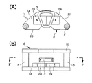
本発明の磁気回路は、磁性体ヨーク及び磁石からなっているもので、これは、図4(A),(B)に示すように、一対のヨーク1a,1bのそれぞれに接着された磁石2a,2bを互いに対向するように配設し、これら一対のヨーク1a,1bを柱状磁性体5,5により所定の間隔をあけて連結してなる磁気回路6の上記磁石2a,2b間の間隙に図4(A),(B)に示したように、可動コイル3を挿入することで、ボイスコイルモータにするものである。
Hereinafter, the present invention will be specifically described with reference to FIG.
The magnetic circuit of the present invention is composed of a magnetic yoke and a magnet, and as shown in FIGS. 4 (A) and 4 (B), this is a
ここで、本発明のボイスコイルモータは、磁性体ヨーク上に、1つの直方体又は平行四辺形柱である磁石を配置するか、或いは2つの直方体又は平行四辺形柱である磁石を磁極の向きが交互になるように、直列に配置したことを特徴とする。 Here, in the voice coil motor of the present invention, a magnet that is one rectangular parallelepiped or a parallelogram pillar is arranged on a magnetic yoke, or two magnets that are parallelogram pillars are arranged in a magnetic pole direction. It is characterized by being arranged in series so as to alternate.
ヨークは、磁気ディスク装置に内蔵できる形状であり、通常、磁気ディスクを収容する四角形状の収容体の一隅部に配設され、三角形状、頂部が切り落とされ又は丸味を帯びた状態の三角形状、これら三角形の底辺部の中央部が半円状、三角形状、頂部が丸味を帯びた三角形状に凹んだ乃至は切り欠かれた扇形状、三日月状乃至半円形リング状の形状を有する。このヨークは、珪素鋼板や炭素鋼等の磁性体で構成され、通常ボルト等で磁気回路を固定するため、貫通孔が端部に設けられている。 The yoke has a shape that can be built in the magnetic disk device, and is usually disposed at one corner of a rectangular container that accommodates the magnetic disk, and has a triangular shape, a triangular shape in which the top is cut off or rounded, The center of these triangles has a semicircular shape, a triangular shape, a fan-like shape that is recessed or cut into a rounded triangular shape, and a crescent-shaped or semi-circular ring-shaped shape. The yoke is made of a magnetic material such as a silicon steel plate or carbon steel, and a through hole is provided at an end portion for fixing the magnetic circuit with a bolt or the like.
上記ヨークの上に、磁石の位置決めを行い、磁石を接着剤で固定する。本発明のように、磁石形状を直方体或いは平行四辺形柱の形状にすることにより、ヨーク上での磁石の位置決めが容易になるものである。これに対し、従来の扇状等の形状のような場合には位置決めが容易にできず、位置決めが悪い場合には、トルクのばらつきといった問題が生じる。 The magnet is positioned on the yoke, and the magnet is fixed with an adhesive. As in the present invention, the magnet can be easily positioned on the yoke by making the magnet shape a rectangular parallelepiped or a parallelogram pillar. On the other hand, in the case of a conventional fan shape or the like, positioning cannot be easily performed, and in the case of poor positioning, there arises a problem of torque variation.
この場合、ヨークに対する磁石の配置態様としては、磁石を1個用いる場合は、図4(A)に示したように、磁石2aの長さ方向がヨーク1aの底辺部13に沿った方向(両側辺部11,11の末端部間を結んだ直線方向)と同方向又はほぼ同方向となるように配置することが好ましく、磁石を2個用いる場合は、図5(A)及び図6(A)に示したように、2個を直列に配置し、その長さ方向がヨーク1aの底辺部13方向と一致するように配置することが好ましい。ここで、図5(A),(B)は、2個の磁石2a,2bを隙間なく当接させて配置した実施態様、図6(A),(B)は、2個の磁石2a,2bを隙間7を介して配置した実施態様であり、その他の構成は図4(A),(B)の磁気回路及びボイスコイルモータと同様である。
In this case, as for the arrangement mode of the magnet with respect to the yoke, when one magnet is used, as shown in FIG. 4A, the length direction of the
なお、上記図4〜6の磁気回路及びボイスコイルモータは、一対のヨーク1a,1bにそれぞれ磁石2a,2bを配置したものであるが、図7〜9に示すように、一対のヨーク1a,1bのうち、一方のヨーク1aに磁石2aを配置し、他方のヨーク1bには磁石を配置せず、磁石2aに対向するように他方のヨーク1bを設けたものであってもよい。この場合、可動コイル3は、磁石2aと他方のヨーク1bとの間に挿入される。ここで、図7は一方のヨーク1aのみに1つの磁石2aを配置した例、図8は一方のヨーク1aのみに2つの磁石2a,2aを隙間を設けずに当接させた状態で直列に配置した例、図9は一方のヨーク1aのみに2つの磁石2a,2aを隙間7を介して直列に配置した例である。
The magnetic circuits and voice coil motors shown in FIGS. 4 to 6 have
各ヨーク上に設けた磁石の個数は、上述したように、1個又は2個であり、1個の場合には、平面方向に磁極が交互になるように、磁石を着磁させる。また2個の場合には、ヨーク方向にNSの磁極が形成されるように着磁してそれぞれの磁極が交互になるように磁石を直列に配置するものである。磁石を2個配置した場合には、これら2個の磁石間の距離は、0〜可動コイルの振れ幅により適宜調整して距離を設定すればよい。 As described above, the number of magnets provided on each yoke is one or two. In the case of one, the magnets are magnetized so that the magnetic poles alternate in the plane direction. In the case of two, magnets are arranged in series so that NS magnetic poles are formed in the yoke direction and the respective magnetic poles are alternated. When two magnets are arranged, the distance between these two magnets may be set by appropriately adjusting the distance between 0 and the swing width of the movable coil.
磁石の固定は、エポキシ樹脂やアクリル樹脂等の耐熱性接着剤が好ましいが、ハードディスク内の発熱の問題から接着レスにして磁石の吸着力により磁石とヨークを固定させてもよい。 A heat-resistant adhesive such as an epoxy resin or an acrylic resin is preferable for fixing the magnet, but the magnet and the yoke may be fixed by an adsorbing force of the magnet without adhesion because of the problem of heat generation in the hard disk.
本発明に用いる磁石は、上述したように、直方体又は平行四辺形柱であり、加工面の点から直方体形状であることが好ましい。通常の磁石は、磁石原料を溶解・粉砕・成形・焼結して製造される焼結磁石や、溶解・粉砕・樹脂成形して製造されるボンド磁石が用いられ、本発明も同様であるが、成形の際に、角型の成形金型を用いることで、磁石の加工時においても、所望の六面体構造に容易に切削加工でき、歩留まりがよい。磁石の加工は、外周刃やワイヤーソーで角型に加工することが有効である。 As described above, the magnet used in the present invention is a rectangular parallelepiped or a parallelogram pillar, and is preferably a rectangular parallelepiped from the viewpoint of the processed surface. Ordinary magnets include sintered magnets manufactured by melting, pulverizing, molding and sintering magnet raw materials, and bonded magnets manufactured by melting, pulverizing and resin molding, and the present invention is also the same. By using a square molding die at the time of molding, the desired hexahedral structure can be easily cut even during machining of the magnet, and the yield is good. It is effective to process the magnet into a square shape with an outer peripheral blade or a wire saw.
また、本発明に用いる磁石は、上記した焼結磁石やボンド磁石を用いることができ、フェライト、アルニコ、希土類系のいずれの磁石でもよい。希土類系の場合は、特に酸化されやすいので、NiやCu等の金属メッキや、酸化防止剤等を塗布しておくことが好ましい。 The magnet used in the present invention may be the above-described sintered magnet or bonded magnet, and may be any one of ferrite, alnico, and rare earth magnets. In the case of a rare earth-based material, it is particularly easy to be oxidized, so it is preferable to apply a metal plating such as Ni or Cu, or an antioxidant.
一対のヨークにそれぞれ磁石が配置された図4〜6の磁気回路の場合、ヨーク上に磁石が貼り合わされた磁気回路は、磁石同士を対向させて、柱状磁性体で空隙間を設けるように組み立てられる。磁気回路間に形成された空隙部に可動コイルが巻かれたアームを挿入することにより、ボイスコイルモータ(VCM)が得られる。一方、図7〜9の磁気回路の場合、磁石の配置された磁性体ヨークと配置されていない磁性体ヨークを対向させて、磁石と磁性体ヨークとの間に形成される空隙部に可動コイルが巻かれたアームを挿入することにより、ボイスコイルモータが得られることになる。対向させる磁気回路は同一特性の磁気回路を対向させる。このように得られたVCMはフレミングの法則に従い、可動コイルを駆動させてアクチュエータに推力を与えるものである。 In the case of the magnetic circuit shown in FIGS. 4 to 6 in which magnets are arranged on a pair of yokes, the magnetic circuit in which the magnets are bonded on the yokes is assembled so that the magnets are opposed to each other and an air gap is provided with a columnar magnetic body. It is done. A voice coil motor (VCM) is obtained by inserting an arm around which a movable coil is wound into a gap formed between magnetic circuits. On the other hand, in the case of the magnetic circuits of FIGS. 7 to 9, the movable yoke is disposed in the gap formed between the magnet and the magnetic yoke, with the magnetic yoke having the magnet disposed thereon and the non-arranged magnetic yoke being opposed to each other. A voice coil motor is obtained by inserting an arm around which is wound. The magnetic circuit to be opposed opposes a magnetic circuit having the same characteristic. The VCM obtained in this way drives the movable coil according to Fleming's law and gives thrust to the actuator.
以下、実施例及び比較例を示し、本発明を具体的に説明するが、本発明は下記の実施例に制限されるものではない。 EXAMPLES Hereinafter, although an Example and a comparative example are shown and this invention is demonstrated concretely, this invention is not restrict | limited to the following Example.
[実施例1]
Nd−Fe−B系焼結磁石(信越化学工業(株)製N48M)を40.4mm×12.4mm×6mmの直方体に加工処理し、厚さ5mmの炭素鋼から構成される磁性体ヨーク上に接着剤を用いて、貼り合わせて、磁極がNSとなるように着磁装置で着磁を行い、磁気回路を製作した。このとき、磁石の固定位置はヨーク中央位置に配置でき、位置決めしやすかった。
[Example 1]
Nd-Fe-B sintered magnet (N48M manufactured by Shin-Etsu Chemical Co., Ltd.) is processed into a 40.4 mm x 12.4 mm x 6 mm cuboid and on a magnetic yoke composed of carbon steel with a thickness of 5 mm The magnetic circuit was manufactured by laminating with an adhesive, and magnetizing with a magnetizing device so that the magnetic pole became NS. At this time, the fixing position of the magnet could be arranged at the yoke central position, and it was easy to position.
磁石間の空隙が10mmになるように柱状磁性体(材質はヨークと同じ)を間に挟み、固定した。その間に銅線で巻かれた可動コイルアームを挿入して図4(A),(B)に示すようなVCMとした。トルク評価結果を図11に示した。 A columnar magnetic body (material is the same as that of the yoke) is sandwiched and fixed so that the gap between the magnets is 10 mm. In the meantime, a movable coil arm wound with a copper wire was inserted to obtain a VCM as shown in FIGS. The torque evaluation results are shown in FIG.
[実施例2]
Nd−Fe−B系焼結磁石(信越化学工業(株)製N48M)を20.2mm×12.4mm×6mmの直方体に加工処理し、厚さ5mmの炭素鋼から構成される磁性体ヨーク上に接着剤を用いて隙間を形成することなく2個直列に貼り付けて、磁極がヨーク方向にNSとなるように着磁して、直列磁石の磁極が交互となるようにした以外は、実施例1と同じように図5(A),(B)に示すようなVCMを作製した。トルク評価結果を図11に示した。
[Example 2]
Nd-Fe-B sintered magnet (N48M manufactured by Shin-Etsu Chemical Co., Ltd.) is processed into a 20.2 mm x 12.4 mm x 6 mm rectangular parallelepiped on a magnetic yoke composed of carbon steel with a thickness of 5 mm Except that the two magnetic poles are bonded in series without forming a gap using an adhesive, and the magnetic poles are magnetized so that they are NS in the yoke direction, so that the magnetic poles of the serial magnets are alternated. As in Example 1, a VCM as shown in FIGS. The torque evaluation results are shown in FIG.
[比較例1]
実施例1における磁石形状を扇型(R29×R16×6mm×60°)にした以外は、実施例1と同じように磁気回路を作製し、図3に示すようなVCMを製造した。トルク評価結果を図11に示した。
[Comparative Example 1]
A magnetic circuit was produced in the same manner as in Example 1 except that the magnet shape in Example 1 was fan-shaped (R29 × R16 × 6 mm × 60 °), and a VCM as shown in FIG. 3 was produced. The torque evaluation results are shown in FIG.
上で得られた実施例、比較例のVCMにつき、下記方法でトルクを測定した。
測定方法:
図10に示したように、VCMコイルを測定軸にセットし、駆動モータを用いて駆動ベルトを介してVCMコイルを回転させ、そのときのトルクをトルク変換器を用いて測定した。結果を図11に示す。
Torque was measured by the following method for the VCMs obtained in the above examples and comparative examples.
Measuring method:
As shown in FIG. 10, the VCM coil was set on the measurement shaft, the VCM coil was rotated through the drive belt using the drive motor, and the torque at that time was measured using the torque converter. The results are shown in FIG.
図11の結果から認められるように、比較的安価にかつ効率よく製造できる棒状の磁石を用いることで、必要なトルクを確保することが可能になった。 As can be seen from the results of FIG. 11, it is possible to secure the necessary torque by using a bar-shaped magnet that can be manufactured relatively inexpensively and efficiently.
1a,1b ヨーク
2a,2b 磁石
3 可動コイル
4 アーム
5 柱状磁性体
6 磁気回路
7 隙間
10 ボイスコイルモータ
11 側辺部
12 頂部
13 底辺部
20 磁気ディスク装置
22 収容体
1a,
Claims (5)
Priority Applications (1)
| Application Number | Priority Date | Filing Date | Title |
|---|---|---|---|
| JP2008065234A JP5035552B2 (en) | 2007-03-20 | 2008-03-14 | Magnetic circuit for voice coil motor and voice coil motor |
Applications Claiming Priority (3)
| Application Number | Priority Date | Filing Date | Title |
|---|---|---|---|
| JP2007072789 | 2007-03-20 | ||
| JP2007072789 | 2007-03-20 | ||
| JP2008065234A JP5035552B2 (en) | 2007-03-20 | 2008-03-14 | Magnetic circuit for voice coil motor and voice coil motor |
Related Child Applications (1)
| Application Number | Title | Priority Date | Filing Date |
|---|---|---|---|
| JP2011277116A Division JP5035578B2 (en) | 2007-03-20 | 2011-12-19 | Magnetic circuit for voice coil motor and voice coil motor |
Publications (2)
| Publication Number | Publication Date |
|---|---|
| JP2008263769A JP2008263769A (en) | 2008-10-30 |
| JP5035552B2 true JP5035552B2 (en) | 2012-09-26 |
Family
ID=39529861
Family Applications (2)
| Application Number | Title | Priority Date | Filing Date |
|---|---|---|---|
| JP2008065234A Expired - Fee Related JP5035552B2 (en) | 2007-03-20 | 2008-03-14 | Magnetic circuit for voice coil motor and voice coil motor |
| JP2011277116A Expired - Fee Related JP5035578B2 (en) | 2007-03-20 | 2011-12-19 | Magnetic circuit for voice coil motor and voice coil motor |
Family Applications After (1)
| Application Number | Title | Priority Date | Filing Date |
|---|---|---|---|
| JP2011277116A Expired - Fee Related JP5035578B2 (en) | 2007-03-20 | 2011-12-19 | Magnetic circuit for voice coil motor and voice coil motor |
Country Status (7)
| Country | Link |
|---|---|
| US (2) | US8194358B2 (en) |
| EP (1) | EP1973107B1 (en) |
| JP (2) | JP5035552B2 (en) |
| KR (1) | KR101048956B1 (en) |
| CN (1) | CN101369770B (en) |
| MY (1) | MY150441A (en) |
| TW (1) | TWI375382B (en) |
Families Citing this family (9)
| Publication number | Priority date | Publication date | Assignee | Title |
|---|---|---|---|---|
| JP5035552B2 (en) | 2007-03-20 | 2012-09-26 | 信越化学工業株式会社 | Magnetic circuit for voice coil motor and voice coil motor |
| JP5035553B2 (en) * | 2007-03-20 | 2012-09-26 | 信越化学工業株式会社 | Magnetic circuit for voice coil motor and voice coil motor |
| US8817375B2 (en) | 2009-01-23 | 2014-08-26 | Kenko Tokina Co., Ltd. | Correction-lens-moving voice coil motor, anti-vibration device, interchangeable lens unit and optical apparatus |
| CA2867843A1 (en) | 2012-04-13 | 2013-10-17 | Sony Corporation | Wireless communication device, information processing device, and communication method |
| JP6146148B2 (en) * | 2013-06-07 | 2017-06-14 | 日立金属株式会社 | Voice coil motor and magnet used for the voice coil motor |
| US10867638B2 (en) * | 2019-01-30 | 2020-12-15 | Seagate Technology Llc | Ultrasonic welding for sealing electronic devices |
| US10916269B2 (en) * | 2019-02-19 | 2021-02-09 | Western Digital Technologies, Inc. | Magnet for motor of magnetic storage device |
| CN120642193A (en) * | 2023-01-24 | 2025-09-12 | Tdk株式会社 | Voice coil actuator |
| US20250079101A1 (en) * | 2023-08-31 | 2025-03-06 | Siemens Industry, Inc. | Magnetic switch for hybrid circuit breaker applications |
Family Cites Families (55)
| Publication number | Priority date | Publication date | Assignee | Title |
|---|---|---|---|---|
| DE2742050A1 (en) * | 1977-09-19 | 1979-03-29 | Papst Motoren Kg | MULTI-PHASE LINEAR MOTOR |
| JPS57103171A (en) | 1980-12-18 | 1982-06-26 | Fujitsu Ltd | Actuator for magnetic recorder |
| US4396966A (en) * | 1980-12-31 | 1983-08-02 | International Business Machines Corporation | Low mass actuator system for magnetic recording disks with half strength end poles |
| US4415941A (en) * | 1981-06-29 | 1983-11-15 | Atasi Corporation | Linear actuator for memory storage device |
| US4506307A (en) * | 1981-11-10 | 1985-03-19 | Ibm | Magnetic head slider and actuator assembly |
| US4439699A (en) * | 1982-01-18 | 1984-03-27 | International Business Machines Corporation | Linear moving coil actuator |
| USD281321S (en) | 1982-11-24 | 1985-11-12 | Maxtor Corporation | Winchester disc drive |
| US4652779A (en) * | 1984-10-30 | 1987-03-24 | Magnetic Peripherals Inc. | Center pole for rotary actuator coil with lowered inductance |
| US5956213A (en) | 1988-01-25 | 1999-09-21 | Seagate Technology, Inc. | Latch mechanism for disk drive using magnetic field of actuator magnets |
| JPH02103783U (en) | 1989-01-27 | 1990-08-17 | ||
| FR2654271B1 (en) | 1989-11-06 | 1992-01-24 | Moving Magnet Tech | ANGULAR SINGLE PHASE ELECTROMAGNETIC ACTUATOR. |
| JPH03173343A (en) | 1989-11-29 | 1991-07-26 | Sony Corp | Moving coil actuator |
| US5808838A (en) | 1990-02-09 | 1998-09-15 | Seagate Technologies, Inc. | Miniature head disc drive system voice coil with single coil and dual stationary magnets |
| JP2696417B2 (en) * | 1990-05-18 | 1998-01-14 | 住友特殊金属株式会社 | Bipolar magnetizer |
| JPH0460971A (en) * | 1990-06-26 | 1992-02-26 | Nec Ibaraki Ltd | Magnetic circuit for magnetic head driving device |
| US5315466A (en) | 1991-03-06 | 1994-05-24 | Fuji Electric Co., Ltd. | Magnetic disk unit having reduced profile and/or faster seek speed |
| JPH04368674A (en) * | 1991-06-17 | 1992-12-21 | Nec Ibaraki Ltd | Magnetic circuit for magnetic head driving device |
| JP2544063B2 (en) * | 1992-06-22 | 1996-10-16 | 株式会社東芝 | Carriage locking method for magnetic disk device and magnetic disk device |
| JPH06178523A (en) | 1992-12-03 | 1994-06-24 | Fujitsu Ltd | Magnetic circuit for voice coil motor |
| US5581422A (en) | 1993-02-09 | 1996-12-03 | Hitachi Metals, Ltd. | Actuator with moveable coil and recording apparatus |
| JP2522179B2 (en) * | 1993-08-10 | 1996-08-07 | 日本電気株式会社 | Magnetic head drive |
| JPH07170712A (en) * | 1993-12-15 | 1995-07-04 | Sumitomo Special Metals Co Ltd | Actuator |
| US5659215A (en) * | 1994-05-19 | 1997-08-19 | Seagate Technology, Inc. | Small form factor actuator for improved functionality and linearity |
| KR100263045B1 (en) | 1994-07-07 | 2000-08-01 | 윤종용 | Method and device for fastening a voice coil motor of a hard disk |
| EP0774153B1 (en) * | 1994-08-02 | 1998-08-26 | Seagate Technology, Inc. | Disk drive including embedded voice coil magnet plates |
| JP3476100B2 (en) | 1995-01-06 | 2003-12-10 | 日立金属株式会社 | Arm assembly and voice coil motor |
| JPH08249846A (en) | 1995-03-13 | 1996-09-27 | Fujitsu Ltd | Rotary actuator for disk device |
| JP3343805B2 (en) | 1995-08-15 | 2002-11-11 | 富士通株式会社 | Disk unit |
| WO1997020310A1 (en) | 1995-11-28 | 1997-06-05 | Micropolis Corporation | Twin coil positioning device for use in a family of hard disk drives having interchangeable magnet components |
| US5621591A (en) | 1996-04-05 | 1997-04-15 | Seagate Technology, Inc. | Dual coil voice coil motor |
| JP3434967B2 (en) | 1996-04-12 | 2003-08-11 | 富士通株式会社 | Actuator structure and recording / reproducing device using the same |
| JP2904177B2 (en) * | 1997-03-21 | 1999-06-14 | 日本電気株式会社 | Head positioning mechanism for magnetic disk drive and drive control method therefor |
| KR19990008845A (en) | 1997-07-04 | 1999-02-05 | 윤종용 | VCM damper on hard disk drive |
| US5999372A (en) | 1997-12-30 | 1999-12-07 | Seagate Technology, Inc. | Actuator arm with streamlined leading edge to reduce air turbulence |
| US6115215A (en) | 1998-02-24 | 2000-09-05 | Seagate Technology, Inc. | Balanced actuator which accesses separate disc assemblies |
| JP2000040314A (en) * | 1998-07-24 | 2000-02-08 | Alps Electric Co Ltd | Head transfer device |
| US6175469B1 (en) | 1998-12-04 | 2001-01-16 | Seagate Technology, Inc. | Disc drive magnet housing electro mechanical resonance dampening system |
| US6268984B1 (en) * | 1999-01-22 | 2001-07-31 | Seagate Technology Llc | Magnet configuration for head-level microactuator |
| US6252744B1 (en) | 1999-03-01 | 2001-06-26 | Seagate Technology Llc | Voice-coil integrated non-contacting magnetic latch for a disc drive actuator assembly |
| JP2001035103A (en) | 1999-07-15 | 2001-02-09 | Fujitsu Ltd | Disk unit |
| MY127853A (en) | 1999-09-08 | 2006-12-29 | Shinetsu Chemical Co | Yoke compartment of voice coil motor for hard disk drive and voice coil motor using said yoke component |
| US6549380B2 (en) * | 2000-04-17 | 2003-04-15 | Seagate Technology Llc | Data handling system with flux-directing voice coil motor |
| JP4554777B2 (en) | 2000-07-17 | 2010-09-29 | パナソニック株式会社 | Actuator for disk device |
| US6608732B2 (en) | 2000-07-26 | 2003-08-19 | Seagate Technology Llc | Damper for disc drive voice coil motor |
| US6606223B2 (en) | 2000-09-27 | 2003-08-12 | Seagate Technology Llc | Voice coil motor dummy magnet |
| JP2002136092A (en) | 2000-10-27 | 2002-05-10 | Matsushita Electric Ind Co Ltd | Voice coil motor |
| JP3464988B2 (en) | 2001-09-21 | 2003-11-10 | 株式会社東芝 | Disk device, yoke incorporated in disk device, and method of manufacturing yoke |
| JP3705214B2 (en) | 2002-01-28 | 2005-10-12 | 松下電器産業株式会社 | Disk unit |
| JP2004023969A (en) | 2002-06-20 | 2004-01-22 | Sumitomo Special Metals Co Ltd | Voice coil motor and magnetic disk unit using it |
| JP2005243177A (en) | 2004-02-27 | 2005-09-08 | Fujitsu Ltd | Magnetic disk unit |
| KR100714101B1 (en) * | 2004-12-08 | 2007-05-02 | 한국전자통신연구원 | Small size optical/magnetic head actuator with a pivot hinge and a halbach array magnet |
| JP2007035184A (en) | 2005-07-28 | 2007-02-08 | Fujitsu Ltd | Magnetic disk unit |
| JP5035553B2 (en) | 2007-03-20 | 2012-09-26 | 信越化学工業株式会社 | Magnetic circuit for voice coil motor and voice coil motor |
| JP5035552B2 (en) | 2007-03-20 | 2012-09-26 | 信越化学工業株式会社 | Magnetic circuit for voice coil motor and voice coil motor |
| CN101345069B (en) | 2007-07-09 | 2011-09-14 | 新科实业有限公司 | Voice coil motor and disk drive unit having the same |
-
2008
- 2008-03-14 JP JP2008065234A patent/JP5035552B2/en not_active Expired - Fee Related
- 2008-03-17 MY MYPI20080711 patent/MY150441A/en unknown
- 2008-03-19 EP EP08250967A patent/EP1973107B1/en not_active Not-in-force
- 2008-03-19 US US12/051,700 patent/US8194358B2/en not_active Expired - Fee Related
- 2008-03-19 KR KR1020080025152A patent/KR101048956B1/en not_active Expired - Fee Related
- 2008-03-19 TW TW097109665A patent/TWI375382B/en not_active IP Right Cessation
- 2008-03-20 CN CN200810168686XA patent/CN101369770B/en not_active Expired - Fee Related
-
2011
- 2011-12-19 JP JP2011277116A patent/JP5035578B2/en not_active Expired - Fee Related
-
2012
- 2012-01-12 US US13/348,893 patent/US20120113548A1/en not_active Abandoned
Also Published As
| Publication number | Publication date |
|---|---|
| KR101048956B1 (en) | 2011-07-12 |
| MY150441A (en) | 2014-01-30 |
| JP2008263769A (en) | 2008-10-30 |
| EP1973107A1 (en) | 2008-09-24 |
| JP5035578B2 (en) | 2012-09-26 |
| US8194358B2 (en) | 2012-06-05 |
| EP1973107B1 (en) | 2011-07-13 |
| US20120113548A1 (en) | 2012-05-10 |
| US20080231997A1 (en) | 2008-09-25 |
| KR20080085743A (en) | 2008-09-24 |
| CN101369770B (en) | 2013-04-17 |
| JP2012100527A (en) | 2012-05-24 |
| TWI375382B (en) | 2012-10-21 |
| CN101369770A (en) | 2009-02-18 |
| TW200845540A (en) | 2008-11-16 |
Similar Documents
| Publication | Publication Date | Title |
|---|---|---|
| JP5035578B2 (en) | Magnetic circuit for voice coil motor and voice coil motor | |
| JP2880280B2 (en) | Single phase electromagnetic angle actuator | |
| CN101345069B (en) | Voice coil motor and disk drive unit having the same | |
| JP5035553B2 (en) | Magnetic circuit for voice coil motor and voice coil motor | |
| JPH10162519A (en) | Magnetic disk drive | |
| JP5153719B2 (en) | Galvano scanner | |
| JP4569451B2 (en) | Optical disk device | |
| JP2014067475A (en) | Base plate for hard disk drive, method for manufacturing the same, and hard disk drive | |
| JP4583713B2 (en) | Magnetic head actuator | |
| US20070223325A1 (en) | Optical disk apparatus | |
| JPH07143720A (en) | Arm assembly and voice-coil motor | |
| JP2003051167A (en) | Magnetic disk drive | |
| JP2005310237A (en) | Objective lens drive | |
| JPS6237055A (en) | Manufacture of linear pulse motor | |
| JPH01177855A (en) | Small-sized linear pulse motor | |
| JP2004335107A (en) | Magnetic disk drive | |
| JP2011123961A (en) | Voice coil motor and magnetic disk device using the same | |
| JP2011222096A (en) | Actuator | |
| JP2005196943A (en) | Magnetic head actuator and magnetic disk device using the same | |
| JPH04307480A (en) | Actuator |
Legal Events
| Date | Code | Title | Description |
|---|---|---|---|
| A621 | Written request for application examination |
Free format text: JAPANESE INTERMEDIATE CODE: A621 Effective date: 20080716 |
|
| A131 | Notification of reasons for refusal |
Free format text: JAPANESE INTERMEDIATE CODE: A131 Effective date: 20110601 |
|
| A521 | Written amendment |
Free format text: JAPANESE INTERMEDIATE CODE: A523 Effective date: 20110719 |
|
| A131 | Notification of reasons for refusal |
Free format text: JAPANESE INTERMEDIATE CODE: A131 Effective date: 20111109 |
|
| A521 | Written amendment |
Free format text: JAPANESE INTERMEDIATE CODE: A523 Effective date: 20111219 |
|
| TRDD | Decision of grant or rejection written | ||
| A01 | Written decision to grant a patent or to grant a registration (utility model) |
Free format text: JAPANESE INTERMEDIATE CODE: A01 Effective date: 20120606 |
|
| A01 | Written decision to grant a patent or to grant a registration (utility model) |
Free format text: JAPANESE INTERMEDIATE CODE: A01 |
|
| A61 | First payment of annual fees (during grant procedure) |
Free format text: JAPANESE INTERMEDIATE CODE: A61 Effective date: 20120619 |
|
| FPAY | Renewal fee payment (event date is renewal date of database) |
Free format text: PAYMENT UNTIL: 20150713 Year of fee payment: 3 |
|
| R150 | Certificate of patent or registration of utility model |
Free format text: JAPANESE INTERMEDIATE CODE: R150 |
|
| LAPS | Cancellation because of no payment of annual fees |