EP1972926A1 - Évaluation des paramètres d'une mesure optique - Google Patents
Évaluation des paramètres d'une mesure optique Download PDFInfo
- Publication number
- EP1972926A1 EP1972926A1 EP07104529A EP07104529A EP1972926A1 EP 1972926 A1 EP1972926 A1 EP 1972926A1 EP 07104529 A EP07104529 A EP 07104529A EP 07104529 A EP07104529 A EP 07104529A EP 1972926 A1 EP1972926 A1 EP 1972926A1
- Authority
- EP
- European Patent Office
- Prior art keywords
- sample
- probe
- interferometer
- parameters
- reflected
- Prior art date
- Legal status (The legal status is an assumption and is not a legal conclusion. Google has not performed a legal analysis and makes no representation as to the accuracy of the status listed.)
- Withdrawn
Links
Images


Classifications
-
- G—PHYSICS
- G01—MEASURING; TESTING
- G01N—INVESTIGATING OR ANALYSING MATERIALS BY DETERMINING THEIR CHEMICAL OR PHYSICAL PROPERTIES
- G01N21/00—Investigating or analysing materials by the use of optical means, i.e. using sub-millimetre waves, infrared, visible or ultraviolet light
- G01N21/17—Systems in which incident light is modified in accordance with the properties of the material investigated
- G01N21/41—Refractivity; Phase-affecting properties, e.g. optical path length
- G01N21/45—Refractivity; Phase-affecting properties, e.g. optical path length using interferometric methods; using Schlieren methods
-
- G—PHYSICS
- G01—MEASURING; TESTING
- G01N—INVESTIGATING OR ANALYSING MATERIALS BY DETERMINING THEIR CHEMICAL OR PHYSICAL PROPERTIES
- G01N21/00—Investigating or analysing materials by the use of optical means, i.e. using sub-millimetre waves, infrared, visible or ultraviolet light
- G01N21/17—Systems in which incident light is modified in accordance with the properties of the material investigated
- G01N21/47—Scattering, i.e. diffuse reflection
Definitions
- the present invention relates to a method and an apparatus for assessing parameters in a material by measurement, such as optical measurement. Thereby material characterization may be conducted non-invasively through accurate extraction of optical parameters.
- OCT optical coherence tomography
- OCT may also be used to extract the optical parameters, such as refractive index (n), scattering coefficient ( ⁇ s ), the so-called g value and absorption coefficient ( ⁇ a ).
- the result is a measurement of the physical composition of the sample relating to both the chemical composition (n and ⁇ a , where ⁇ a is the parameter commonly probed through spectroscopy) and size, shape and contents of particles (g and ⁇ a ).
- a generic OCT system is shown in a schematic form in Figure 1 .
- the beam is chosen to have a long focal length so that the spot size of the beam is relatively constant at the part where the system measures (typical the first 1-2 mm). This has the drawback that the spot size in the sample must be rather large (eg. 10-15 ⁇ m).
- the focal length is a measure of how much the beam diameter varies before and after the focal plane (the position where the beam diameter is minimal).
- dynamic focusing results in superior images compared to fixed focus.
- a sharper focus is chosen to obtain a smaller spot size in the focal plane (2-5 ⁇ m), which in turn gives better resolution.
- this implementation results in added complexity.
- To obtain the advantage of dynamic focusing the position of the focal plane has to be matched to the point measured by the OCT system.
- time-domain OCT system this means that the distance to the reference mirror has to be matched to the distance to focal plane in the sample.
- the probe-head has to incorporate a method of moving the focal plane in the sample. This could for example be done by moving the focusing lens mechanically.
- An example of implementation of dynamic focusing is the OCT system produced by ISIS Optronics, see for example US 6,970,22 .
- the present invention provides a novel probe configuration by use of which a variety of parameters from a sample material is obtainable.
- a method for assessing at least one quality and/or quantity parameter in a material comprising
- a coherence interferometry and/or reflectometry system for assessing at least one quality and/or quantity parameter in a homogenous material, said system comprising
- a probe for use in a system comprising an optical system with a fixed lens capable of providing a focused light beam.
- the present invention may be used for determination provide for a variety of quantity or quality parameters, such as concentration, particle size, and/or chemical composition.
- the invention may be applied for example when measuring mixtures in tanks, characterisation of plastics and polymers, as well as medical diagnostics.
- a 1 D measurement is also called an A-scan.
- the reflectivity is measured as a function of depth.
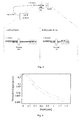
- Figure 2 is an example of such an A-scan where the reflectivity is recorded for two different samples as the function of depth in ⁇ m.
- the red curve the sample exhibits a low entrance reflection and a large reflection from the backside of the sample at about 1200 ⁇ m.
- the sample with the blue curve shows a high entrance peak and very little reflectivity from the backside at 1250 ⁇ m.
- A-scans may be obtained from measurements in a single surface position, or as an average of several measurements from different positions.
- a material comprising one or more components, such as a solvent with particles, in such a way that the mean scattering parameters are substantially uniform.
- An examples of non-homogeneous materials are stratified materials consisting of layers of materials with different scattering parameters.
- the present invention relates to a system and a method for extracting parameters from a material in order to provide characteristic information from said material.
- a beam penetrates a material, for example tissue
- a fraction given by ⁇ s is scattered at each depth and the rest passes straight through.
- a part of the scattered beam is reflected straight back and can be detected by the system according to the invention, but most is only deviated from its original course. How much deviation is described by the g -parameter and this relates to the particle size, shape, and its difference in refractive index from the surroundings.
- the measurement by interferometry and/or reflectometry is unique in that it has the potential to measure g and ⁇ s separately. This is because a small portion of the scattered beam finds it way back into the path of the unscattered beam. Accordingly, measurement of the properties has the potential of revealing both particle size and concentration.
- the g value which ranges from -1 to 1, is very close to 1. This means the light scattered from a particle will deviate very little from its initial course. As g approaches 1 it is increasingly difficult to distinguish the situation where the scattering concentration is high, but each scattering means very little, from the situation where the scattering concentration is lower but with a higher effect. This is illustrated in the comparative examples 1 and 2.
- the present invention relates to a method for assessing at least one quality and/or quantity parameter in a material, said method comprising
- the present invention avoids active parts in that the probe is a fixed but highly focusing lens. This setup is unsuitable for imaging, but has been found to be very suitable for measuring the parameters used in the present invention.
- wave source refers to a source providing the relevant waves, such as a light source, an acoustic source, an ultra-sound source, a radar, etc.
- a light source may be selected from one of the two main categories:
- any optical coherence interferometry and/or reflectometry system suitable for the method may be used, the requirement is that the system should be able to resolve reflectivity as a function of distance.
- systems are an optical low-coherence interferometer reflectometry (OLCR) system, a white-light interferometry system, an optical time-domain reflectometry (OTDR) system, an optical coherence tomography (OCT) system, a Lidar system, a radar system, a low time-coherence interferometer (LCI) and an ultrasound system.
- the system is an OCT system comprising further an interferometer, a sample arm and a reference arm, wherein the interferometer is arranged to split a light beam from said light source into two light beams into the sample arm and the reference arm, respectively, whereby the method comprises
- the OCT system may be a time domain OCT system wherein the path length of the reference arm is translated longitudinally in time, or a frequency domain OCT system selected from spectral-OCT and wavelength swept-OCT.
- frequency domain OCT the broadband interference is acquired with spectrally separated detectors. Due to the Fourier relation the depth scan can be immediately calculated by a Fourier-transform from the acquired spectra without movement of the reference arm.
- Any suitable light source may be used in the system. There are two main categories:
- the light source may be selected from the group of superluminiscent light diodes (SLD), other sources based on amplified spontaneous emission (ASE) preferably fibre-based, femtosecond lasers such as Kerr Lens based, e.g. Ti : sapphire laser or Cr : forsterite, LED, Super-fluorescence such as Yb-doped fibre, Erdoped fibre or,Tm-doped, Photonic crystal fibre preferably pumped by high intensity lasers such femtosecond, picosecond and CW, and thermal sources such as tungsten or halogen based.
- SLD superluminiscent light diodes
- ASE amplified spontaneous emission
- femtosecond lasers such as Kerr Lens based, e.g. Ti : sapphire laser or Cr : forsterite, LED
- Super-fluorescence such as Yb-doped fibre, Erdoped fibre or,Tm-doped
- Photonic crystal fibre preferably pumped by
- the interferometer for splitting the light beam is typically a Michelson's interferometer. For most applications it is preferred that the combination of light beams is conducted in the interferometer.
- the reference arm may be constructed in several suitable ways, it is however preferred that the reference arm comprises reflection means.
- the advantages of the present invention are provided by the configuration of the probe.
- the probe comprises an optical system with a fixed lens capable of providing a highly focused light beam which is contrary to the conventional fixed focus probe wherein the depth of focus is long.
- a highly focused light beam means that the depth of focus is less than the penetration depth which is sub-optimal for imaging.
- the generalized depth of focus understood as the distance from the minimum area of the beam to where the area has doubled, is less than the penetration depth, preferably less than 50% of the penetration depth, more preferably less than 25% of the penetration depth, less than 10% of the penetration depth, less than 5% of the penetration depth, less than 1% of the penetration depth, less than 0.1 % of the penetration depth, or most preferably less than 0.01 % of the penetration depth.
- the focus depth is in the range of more than 0.01 mm, such as more than 0.05 mm, such as preferably more than 0.1 mm, such as more than 0.15 mm, such as more than 0.2mm, such as more than 0.5 mm, such as more than 1 mm.
- two measurements such as two measurements simultaneously.
- this may be achieved by splitting the probe light up into two arms each with either different focusing lenses and/or different distance to the sample.
- the measurement from these two arms may be separated by multiplexing and/or the two arms may have different lengths, so that there is no overlap for each position of the reference arm.
- the probe may be designed in any suitable manner fulfilling the requirements for focusing and fixability.
- the probe is fibre based, in another free-space in incorporated into the probe in order to connect the optical path of the probe.
- a combination of fibres and free-space may also be envisaged.
- the present invention offers the possibility of extracting a variety of parameters from the measurements by providing a probe having a sufficiently high focus.
- the following parameters may be extracted, see also the presentation in Figure 9 :
- sample material may be characterised with respect to one or more quality and/or quantity parameters.
- the one or more quality and/or quantity parameter(s) may be selected from
- the at least one quality and/or quantity parameter is the size of particles in the material.
- the method according to the invention also allows for determination of the size of at least two different particles, such as the size of at least three different particles.
- the at least one quality and/or quantity parameter is the concentration of particles in the sample material.
- the at least one quality and/or quantity parameter is the chemical composition.
- Figure 10 shows schematically a system according to the invention as well as a graphic representation of the results obtained.
- the coordinate z describes the longitudinal axis and is set to zero at the surface of the sample.
- a device to measure the distance between the lens and sample such as e.g. a laser interferometer.
- the next step is to relate these values to the concentration and size of the scattering particles.
- these coefficients are in themselves indicative of the state of the sample and it is therefore sufficient obtain these values.
- the method according to the present invention is more robust for g ⁇ 1, which is often the case for tissue and tissue-like materials.
- ⁇ is the volume fraction of the scatterers
- V is the volume of a single scatterer
- N is the number of particles within a unit volume
- C is the total scattering cross section of a particle.
- p ( ⁇ ) is the normalized phase function describing the probability of a scattered photon exiting at angle ⁇ relative to the incident direction
- P ( ⁇ ) is the unnormalized phase function, which in turn is the average of the scattering pattern F s ( ⁇ , ⁇ ) over the azimuthal angle ⁇ .
- phase function and scattering pattern are related to the shape of the particle, i.e. also its volume, and the refractive index of the particle. Accordingly, g is related to the particle shape and size so to e.g. estimate size knowledge of the refractive index and shape of the particles is needed. If the possible particle types are known values for g may be established from reference measurements. Other methods are available to a person skilled in art such as:
- spectroscopic information i.e. the parameters as a function of wavelength
- multivariate analysis may be applied to derive the contents of the sample.
- Several methods exist in the field of multivariate analysis which is often applied in spectral analysis, e.g. in IR-spectroscopy.
- One method is to find the wave length dependency of the optical properties for each type of scatterer, e.g. by reference experiments, and then find the composition of scatters from the multivariate analysis.
- Another approach is to apply neural network methods where the analysis software is taught how to recognise compositions from dataset taken from known reference samples.
- the wave length dependency may be measured using several broadband light sources centred at different wavelengths.
- the spectra of these may be chosen to be overlapping or non-overlapping.
- the optical parameters will then be measured as an average value over the bandwidth of each light source.
- Another method is to apply one very broadband light source and then apply different sections of the spectrum and/or use spectral analysis to calculate the wavelength dependency of the optical properties.
- a Gaussian shaped band-pass filter is scanned over the practically uniform broadband light sources.
- the sample material may be any material wherein determination of one or more quality and/or quantity parameter(s) is desirable. It is preferred that the material is not layered, and it is more preferred that the material is homogenous or approximated to a homogenous material.
- the material may be a liquid material, such as a liquid material selected from the group of milk, waste water, blood, dairy products, chemical mixtures, mixtures for production of medicine, beer, wine, molten mixtures, such as silica for production of silica-wafers.
- a liquid material selected from the group of milk, waste water, blood, dairy products, chemical mixtures, mixtures for production of medicine, beer, wine, molten mixtures, such as silica for production of silica-wafers.
- the material is a solid material or semi-solid material, such as a polymer, human and animal tissue, such as skin, gastro-intestinal, larynx, gums, blatter, brain, retinal, coronary wall, as well as lesions and tumors in these areas.
- a solid material or semi-solid material such as a polymer, human and animal tissue, such as skin, gastro-intestinal, larynx, gums, blatter, brain, retinal, coronary wall, as well as lesions and tumors in these areas.
- the material is a gas, such as a smoke gas, pollutens, combustion gasses and bi-products.
- the method of the present invention may be combined with other types of measurement in order to increase accuracy.
- an additional method applied in the art called a distributed reflectivity measurement (DFM) may be combined with the proposed invention to measure the absorption.
- DFM distributed reflectivity measurement
- the model based on EHF may by designed to include absorption, however, there may be too many degrees of freedom to make an accurate fit. If so DFM may allow for the extraction of the absorption, by measuring ⁇ a , and ⁇ s (1- g ) in a different way than discussed herein above, but still using the probe beam from the system.
- a DFM measurement is typically performed by measuring the beam reflected from the sample into collection fibers (usually multimode) located at a distance from the probe fiber.
- the signal received in the collection fibers are analysed using established theoretical models based on diffusion theory.
- change of setting could be done by splitting the probe beam up into two arms each with either different focusing lenses and/or different distance to the sample.
- the measurement from these two arms may be separated by multiplexing or by the two arms having different lengths, so that there are no overlaps for each position of the reference arm.
- This reflection may be a mirror with a specular reflection, a transparent layer, and/or a reflector with a diffusely reflecting surface. The latter is often preferred as this provides a reflection which is substantially not influences by exact alignment and drift or changes in polarisation such as those induced by twisten the fibre going from the interferometer and the probe in a fiber-based system.
- a vibrating device may be attached to the probe head to introduce a slight motion relative to the sample.
- the aim is to obtain a spatial averaging which is assumed in the EHF theory.
- a change in focal position from 0.2 to 0.3 mm in the sample for the red curve results in the following curve in Figure 6 .
- the best and most advanced type of dynamic focusing is used where a feed-back system is used to ensure that the beam is always focus at the same depth where the OCT system is measuring.
- the set of beam parameters has been chosen so that the focal length of the lens is 2mm and the initial beam radius is 0.5mm. This results in a spot size of about 3 ⁇ m.
Landscapes
- Physics & Mathematics (AREA)
- Health & Medical Sciences (AREA)
- Life Sciences & Earth Sciences (AREA)
- Chemical & Material Sciences (AREA)
- Analytical Chemistry (AREA)
- Biochemistry (AREA)
- General Health & Medical Sciences (AREA)
- General Physics & Mathematics (AREA)
- Immunology (AREA)
- Pathology (AREA)
- Investigating Or Analysing Materials By Optical Means (AREA)
Priority Applications (1)
| Application Number | Priority Date | Filing Date | Title |
|---|---|---|---|
| EP07104529A EP1972926A1 (fr) | 2007-03-20 | 2007-03-20 | Évaluation des paramètres d'une mesure optique |
Applications Claiming Priority (1)
| Application Number | Priority Date | Filing Date | Title |
|---|---|---|---|
| EP07104529A EP1972926A1 (fr) | 2007-03-20 | 2007-03-20 | Évaluation des paramètres d'une mesure optique |
Publications (1)
| Publication Number | Publication Date |
|---|---|
| EP1972926A1 true EP1972926A1 (fr) | 2008-09-24 |
Family
ID=38325685
Family Applications (1)
| Application Number | Title | Priority Date | Filing Date |
|---|---|---|---|
| EP07104529A Withdrawn EP1972926A1 (fr) | 2007-03-20 | 2007-03-20 | Évaluation des paramètres d'une mesure optique |
Country Status (1)
| Country | Link |
|---|---|
| EP (1) | EP1972926A1 (fr) |
Cited By (4)
| Publication number | Priority date | Publication date | Assignee | Title |
|---|---|---|---|---|
| WO2010031161A1 (fr) * | 2008-09-16 | 2010-03-25 | Her Majesty The Queen In Right Of Canada As Represented By The Minister Of Defence | Détermination à distance de la dimension et de la concentration d'aérosols à faible concentration |
| CN102959744A (zh) * | 2011-06-29 | 2013-03-06 | 松下电器产业株式会社 | 发光元件的制造方法及发光元件的制造装置 |
| CN106248624A (zh) * | 2016-09-12 | 2016-12-21 | 南京理工大学 | 基于补偿干涉仪的串联式全场光学层析成像装置及方法 |
| CN115791090A (zh) * | 2023-02-08 | 2023-03-14 | 武汉昊衡科技有限公司 | 一种提高信号测量灵敏度及偏振稳定性的系统及方法 |
Citations (1)
| Publication number | Priority date | Publication date | Assignee | Title |
|---|---|---|---|---|
| US6256102B1 (en) * | 1999-04-27 | 2001-07-03 | University Of Central Florida | Dual-beam low-coherence interferometer with improved signal-to-noise ratio |
-
2007
- 2007-03-20 EP EP07104529A patent/EP1972926A1/fr not_active Withdrawn
Patent Citations (1)
| Publication number | Priority date | Publication date | Assignee | Title |
|---|---|---|---|---|
| US6256102B1 (en) * | 1999-04-27 | 2001-07-03 | University Of Central Florida | Dual-beam low-coherence interferometer with improved signal-to-noise ratio |
Non-Patent Citations (5)
| Title |
|---|
| ESENALIEV R O ET AL: "Accurate measurement of total attenuation coefficient of thin tissue with optical coherence tomography", IEEE JOURNAL OF SELECTED TOPICS IN QUANTUM ELECTRONICS, IEEE SERVICE CENTER, PISCATAWAY, NJ, US, vol. 9, no. 2, March 2003 (2003-03-01), pages 210 - 221, XP011102887, ISSN: 1077-260X * |
| FABER D J ET AL: "Quantitative measurement of attenuation coefficients of weakly scattering media using optical coherence tomography", OPTICS EXPRESS OPT. SOC. AMERICA USA, vol. 12, no. 19, 20 September 2004 (2004-09-20), XP002446372, ISSN: 1094-4087 * |
| IZATT J A ET AL: "OPTICAL COHERENCE MICROSCOPY IN SCATTERING MEDIA", OPTICS LETTERS, OSA, OPTICAL SOCIETY OF AMERICA, WASHINGTON, DC, US, vol. 19, no. 8, 15 April 1994 (1994-04-15), pages 590 - 592, XP000440040, ISSN: 0146-9592 * |
| KNUTTEL A ET AL: "New method for evaluation of in vivo scattering and refractive index properties obtained with optical coherence tomography", JOURNAL OF BIOMEDICAL OPTICS SPIE USA, vol. 9, no. 2, March 2004 (2004-03-01), pages 265 - 273, XP002446373, ISSN: 1083-3668 * |
| RANDALL S L ET AL: "Optical low-coherence reflectometry for nondestructive process measurements", AIP CONFERENCE PROCEEDINGS AIP USA, no. 657B, 2003, pages 1713 - 1720, XP002446374, ISSN: 0094-243X * |
Cited By (7)
| Publication number | Priority date | Publication date | Assignee | Title |
|---|---|---|---|---|
| WO2010031161A1 (fr) * | 2008-09-16 | 2010-03-25 | Her Majesty The Queen In Right Of Canada As Represented By The Minister Of Defence | Détermination à distance de la dimension et de la concentration d'aérosols à faible concentration |
| CN102959744A (zh) * | 2011-06-29 | 2013-03-06 | 松下电器产业株式会社 | 发光元件的制造方法及发光元件的制造装置 |
| CN102959744B (zh) * | 2011-06-29 | 2015-08-19 | 松下电器产业株式会社 | 发光元件的制造方法及发光元件的制造装置 |
| US9241388B2 (en) | 2011-06-29 | 2016-01-19 | Panasonic Intellectual Property Management Co., Ltd. | Method and apparatus for manufacturing a light-emitting device including correction of an application amount of a fluorescent resin based on a fluorescent particle concentration |
| CN106248624A (zh) * | 2016-09-12 | 2016-12-21 | 南京理工大学 | 基于补偿干涉仪的串联式全场光学层析成像装置及方法 |
| CN106248624B (zh) * | 2016-09-12 | 2020-01-03 | 南京理工大学 | 基于补偿干涉仪的串联式全场光学层析成像装置及方法 |
| CN115791090A (zh) * | 2023-02-08 | 2023-03-14 | 武汉昊衡科技有限公司 | 一种提高信号测量灵敏度及偏振稳定性的系统及方法 |
Similar Documents
| Publication | Publication Date | Title |
|---|---|---|
| EP2444783B1 (fr) | Systèmes et procédé pour interférométrie à faible cohérence à résolution angulaire endoscopique à base de fibre | |
| Schmitt et al. | Measurement of optical properties of biological tissues by low-coherence reflectometry | |
| US6611339B1 (en) | Phase dispersive tomography | |
| US6847456B2 (en) | Methods and systems using field-based light scattering spectroscopy | |
| US20090219544A1 (en) | Systems, methods and computer-accessible medium for providing spectral-domain optical coherence phase microscopy for cell and deep tissue imaging | |
| US10292595B2 (en) | Systems and methods for endoscopic angle-resolved low coherence interferometry | |
| EP2306141A1 (fr) | Procédés et systèmes destinés à réaliser une tomographie par cohérence optique dans le domaine de Fourier avec résolution angulaire | |
| JP2000046729A (ja) | 波長分散を用いた高速光断層像計測装置および計測方法 | |
| JP2006517028A (ja) | 無接触温度モニタ及び制御方法及び装置 | |
| EP1972926A1 (fr) | Évaluation des paramètres d'une mesure optique | |
| Blatter et al. | High-speed functional OCT with self-reconstructive bessel illumination at 1300nm | |
| US20220276161A1 (en) | A method of imaging a sample material | |
| Buist et al. | Theoretical and experimental determination of the confocal function of OCT systems for accurate calculation of sample optical properties | |
| Pircher et al. | Measurement of water absorption in human cornea with differential absorption optical coherence tomography | |
| Popescu et al. | Optical characterization of volume-scattering backgrounds | |
| Pircher et al. | Absorption and dispersion measurements of water, D2O, and acetone by phase resolved PCI and OCT in the mid-infrared range 1.3 um to 2.0 um |
Legal Events
| Date | Code | Title | Description |
|---|---|---|---|
| PUAI | Public reference made under article 153(3) epc to a published international application that has entered the european phase |
Free format text: ORIGINAL CODE: 0009012 |
|
| AK | Designated contracting states |
Kind code of ref document: A1 Designated state(s): AT BE BG CH CY CZ DE DK EE ES FI FR GB GR HU IE IS IT LI LT LU LV MC MT NL PL PT RO SE SI SK TR |
|
| AX | Request for extension of the european patent |
Extension state: AL BA HR MK RS |
|
| AKX | Designation fees paid | ||
| REG | Reference to a national code |
Ref country code: DE Ref legal event code: 8566 |
|
| STAA | Information on the status of an ep patent application or granted ep patent |
Free format text: STATUS: THE APPLICATION IS DEEMED TO BE WITHDRAWN |
|
| 18D | Application deemed to be withdrawn |
Effective date: 20090325 |