EP1972871A2 - Hot water system - Google Patents
Hot water system Download PDFInfo
- Publication number
- EP1972871A2 EP1972871A2 EP20070254438 EP07254438A EP1972871A2 EP 1972871 A2 EP1972871 A2 EP 1972871A2 EP 20070254438 EP20070254438 EP 20070254438 EP 07254438 A EP07254438 A EP 07254438A EP 1972871 A2 EP1972871 A2 EP 1972871A2
- Authority
- EP
- European Patent Office
- Prior art keywords
- refrigerant
- temperature
- pressure
- detection means
- heat exchanger
- Prior art date
- Legal status (The legal status is an assumption and is not a legal conclusion. Google has not performed a legal analysis and makes no representation as to the accuracy of the status listed.)
- Granted
Links
Images

Classifications
-
- F—MECHANICAL ENGINEERING; LIGHTING; HEATING; WEAPONS; BLASTING
- F25—REFRIGERATION OR COOLING; COMBINED HEATING AND REFRIGERATION SYSTEMS; HEAT PUMP SYSTEMS; MANUFACTURE OR STORAGE OF ICE; LIQUEFACTION SOLIDIFICATION OF GASES
- F25B—REFRIGERATION MACHINES, PLANTS OR SYSTEMS; COMBINED HEATING AND REFRIGERATION SYSTEMS; HEAT PUMP SYSTEMS
- F25B49/00—Arrangement or mounting of control or safety devices
- F25B49/02—Arrangement or mounting of control or safety devices for compression type machines, plants or systems
- F25B49/027—Condenser control arrangements
-
- F—MECHANICAL ENGINEERING; LIGHTING; HEATING; WEAPONS; BLASTING
- F24—HEATING; RANGES; VENTILATING
- F24D—DOMESTIC- OR SPACE-HEATING SYSTEMS, e.g. CENTRAL HEATING SYSTEMS; DOMESTIC HOT-WATER SUPPLY SYSTEMS; ELEMENTS OR COMPONENTS THEREFOR
- F24D19/00—Details
- F24D19/10—Arrangement or mounting of control or safety devices
- F24D19/1006—Arrangement or mounting of control or safety devices for water heating systems
- F24D19/1051—Arrangement or mounting of control or safety devices for water heating systems for domestic hot water
- F24D19/1054—Arrangement or mounting of control or safety devices for water heating systems for domestic hot water the system uses a heat pump
-
- F—MECHANICAL ENGINEERING; LIGHTING; HEATING; WEAPONS; BLASTING
- F24—HEATING; RANGES; VENTILATING
- F24H—FLUID HEATERS, e.g. WATER OR AIR HEATERS, HAVING HEAT-GENERATING MEANS, e.g. HEAT PUMPS, IN GENERAL
- F24H15/00—Control of fluid heaters
- F24H15/20—Control of fluid heaters characterised by control inputs
- F24H15/227—Temperature of the refrigerant in heat pump cycles
-
- F—MECHANICAL ENGINEERING; LIGHTING; HEATING; WEAPONS; BLASTING
- F24—HEATING; RANGES; VENTILATING
- F24H—FLUID HEATERS, e.g. WATER OR AIR HEATERS, HAVING HEAT-GENERATING MEANS, e.g. HEAT PUMPS, IN GENERAL
- F24H15/00—Control of fluid heaters
- F24H15/20—Control of fluid heaters characterised by control inputs
- F24H15/242—Pressure
-
- F—MECHANICAL ENGINEERING; LIGHTING; HEATING; WEAPONS; BLASTING
- F24—HEATING; RANGES; VENTILATING
- F24H—FLUID HEATERS, e.g. WATER OR AIR HEATERS, HAVING HEAT-GENERATING MEANS, e.g. HEAT PUMPS, IN GENERAL
- F24H15/00—Control of fluid heaters
- F24H15/30—Control of fluid heaters characterised by control outputs; characterised by the components to be controlled
- F24H15/375—Control of heat pumps
- F24H15/38—Control of compressors of heat pumps
-
- F—MECHANICAL ENGINEERING; LIGHTING; HEATING; WEAPONS; BLASTING
- F24—HEATING; RANGES; VENTILATING
- F24H—FLUID HEATERS, e.g. WATER OR AIR HEATERS, HAVING HEAT-GENERATING MEANS, e.g. HEAT PUMPS, IN GENERAL
- F24H15/00—Control of fluid heaters
- F24H15/30—Control of fluid heaters characterised by control outputs; characterised by the components to be controlled
- F24H15/375—Control of heat pumps
- F24H15/385—Control of expansion valves of heat pumps
-
- F—MECHANICAL ENGINEERING; LIGHTING; HEATING; WEAPONS; BLASTING
- F25—REFRIGERATION OR COOLING; COMBINED HEATING AND REFRIGERATION SYSTEMS; HEAT PUMP SYSTEMS; MANUFACTURE OR STORAGE OF ICE; LIQUEFACTION SOLIDIFICATION OF GASES
- F25B—REFRIGERATION MACHINES, PLANTS OR SYSTEMS; COMBINED HEATING AND REFRIGERATION SYSTEMS; HEAT PUMP SYSTEMS
- F25B41/00—Fluid-circulation arrangements
- F25B41/30—Expansion means; Dispositions thereof
- F25B41/39—Dispositions with two or more expansion means arranged in series, i.e. multi-stage expansion, on a refrigerant line leading to the same evaporator
-
- F—MECHANICAL ENGINEERING; LIGHTING; HEATING; WEAPONS; BLASTING
- F25—REFRIGERATION OR COOLING; COMBINED HEATING AND REFRIGERATION SYSTEMS; HEAT PUMP SYSTEMS; MANUFACTURE OR STORAGE OF ICE; LIQUEFACTION SOLIDIFICATION OF GASES
- F25B—REFRIGERATION MACHINES, PLANTS OR SYSTEMS; COMBINED HEATING AND REFRIGERATION SYSTEMS; HEAT PUMP SYSTEMS
- F25B13/00—Compression machines, plants or systems, with reversible cycle
-
- F—MECHANICAL ENGINEERING; LIGHTING; HEATING; WEAPONS; BLASTING
- F25—REFRIGERATION OR COOLING; COMBINED HEATING AND REFRIGERATION SYSTEMS; HEAT PUMP SYSTEMS; MANUFACTURE OR STORAGE OF ICE; LIQUEFACTION SOLIDIFICATION OF GASES
- F25B—REFRIGERATION MACHINES, PLANTS OR SYSTEMS; COMBINED HEATING AND REFRIGERATION SYSTEMS; HEAT PUMP SYSTEMS
- F25B2313/00—Compression machines, plants or systems with reversible cycle not otherwise provided for
- F25B2313/027—Compression machines, plants or systems with reversible cycle not otherwise provided for characterised by the reversing means
- F25B2313/02741—Compression machines, plants or systems with reversible cycle not otherwise provided for characterised by the reversing means using one four-way valve
-
- F—MECHANICAL ENGINEERING; LIGHTING; HEATING; WEAPONS; BLASTING
- F25—REFRIGERATION OR COOLING; COMBINED HEATING AND REFRIGERATION SYSTEMS; HEAT PUMP SYSTEMS; MANUFACTURE OR STORAGE OF ICE; LIQUEFACTION SOLIDIFICATION OF GASES
- F25B—REFRIGERATION MACHINES, PLANTS OR SYSTEMS; COMBINED HEATING AND REFRIGERATION SYSTEMS; HEAT PUMP SYSTEMS
- F25B2339/00—Details of evaporators; Details of condensers
- F25B2339/04—Details of condensers
- F25B2339/047—Water-cooled condensers
-
- F—MECHANICAL ENGINEERING; LIGHTING; HEATING; WEAPONS; BLASTING
- F25—REFRIGERATION OR COOLING; COMBINED HEATING AND REFRIGERATION SYSTEMS; HEAT PUMP SYSTEMS; MANUFACTURE OR STORAGE OF ICE; LIQUEFACTION SOLIDIFICATION OF GASES
- F25B—REFRIGERATION MACHINES, PLANTS OR SYSTEMS; COMBINED HEATING AND REFRIGERATION SYSTEMS; HEAT PUMP SYSTEMS
- F25B2500/00—Problems to be solved
- F25B2500/19—Calculation of parameters
-
- F—MECHANICAL ENGINEERING; LIGHTING; HEATING; WEAPONS; BLASTING
- F25—REFRIGERATION OR COOLING; COMBINED HEATING AND REFRIGERATION SYSTEMS; HEAT PUMP SYSTEMS; MANUFACTURE OR STORAGE OF ICE; LIQUEFACTION SOLIDIFICATION OF GASES
- F25B—REFRIGERATION MACHINES, PLANTS OR SYSTEMS; COMBINED HEATING AND REFRIGERATION SYSTEMS; HEAT PUMP SYSTEMS
- F25B2600/00—Control issues
- F25B2600/02—Compressor control
- F25B2600/025—Compressor control by controlling speed
-
- F—MECHANICAL ENGINEERING; LIGHTING; HEATING; WEAPONS; BLASTING
- F25—REFRIGERATION OR COOLING; COMBINED HEATING AND REFRIGERATION SYSTEMS; HEAT PUMP SYSTEMS; MANUFACTURE OR STORAGE OF ICE; LIQUEFACTION SOLIDIFICATION OF GASES
- F25B—REFRIGERATION MACHINES, PLANTS OR SYSTEMS; COMBINED HEATING AND REFRIGERATION SYSTEMS; HEAT PUMP SYSTEMS
- F25B2600/00—Control issues
- F25B2600/19—Refrigerant outlet condenser temperature
-
- F—MECHANICAL ENGINEERING; LIGHTING; HEATING; WEAPONS; BLASTING
- F25—REFRIGERATION OR COOLING; COMBINED HEATING AND REFRIGERATION SYSTEMS; HEAT PUMP SYSTEMS; MANUFACTURE OR STORAGE OF ICE; LIQUEFACTION SOLIDIFICATION OF GASES
- F25B—REFRIGERATION MACHINES, PLANTS OR SYSTEMS; COMBINED HEATING AND REFRIGERATION SYSTEMS; HEAT PUMP SYSTEMS
- F25B2600/00—Control issues
- F25B2600/21—Refrigerant outlet evaporator temperature
-
- F—MECHANICAL ENGINEERING; LIGHTING; HEATING; WEAPONS; BLASTING
- F25—REFRIGERATION OR COOLING; COMBINED HEATING AND REFRIGERATION SYSTEMS; HEAT PUMP SYSTEMS; MANUFACTURE OR STORAGE OF ICE; LIQUEFACTION SOLIDIFICATION OF GASES
- F25B—REFRIGERATION MACHINES, PLANTS OR SYSTEMS; COMBINED HEATING AND REFRIGERATION SYSTEMS; HEAT PUMP SYSTEMS
- F25B2600/00—Control issues
- F25B2600/25—Control of valves
- F25B2600/2513—Expansion valves
-
- F—MECHANICAL ENGINEERING; LIGHTING; HEATING; WEAPONS; BLASTING
- F25—REFRIGERATION OR COOLING; COMBINED HEATING AND REFRIGERATION SYSTEMS; HEAT PUMP SYSTEMS; MANUFACTURE OR STORAGE OF ICE; LIQUEFACTION SOLIDIFICATION OF GASES
- F25B—REFRIGERATION MACHINES, PLANTS OR SYSTEMS; COMBINED HEATING AND REFRIGERATION SYSTEMS; HEAT PUMP SYSTEMS
- F25B2700/00—Sensing or detecting of parameters; Sensors therefor
- F25B2700/19—Pressures
- F25B2700/193—Pressures of the compressor
- F25B2700/1931—Discharge pressures
-
- F—MECHANICAL ENGINEERING; LIGHTING; HEATING; WEAPONS; BLASTING
- F25—REFRIGERATION OR COOLING; COMBINED HEATING AND REFRIGERATION SYSTEMS; HEAT PUMP SYSTEMS; MANUFACTURE OR STORAGE OF ICE; LIQUEFACTION SOLIDIFICATION OF GASES
- F25B—REFRIGERATION MACHINES, PLANTS OR SYSTEMS; COMBINED HEATING AND REFRIGERATION SYSTEMS; HEAT PUMP SYSTEMS
- F25B2700/00—Sensing or detecting of parameters; Sensors therefor
- F25B2700/21—Temperatures
- F25B2700/2115—Temperatures of a compressor or the drive means therefor
- F25B2700/21152—Temperatures of a compressor or the drive means therefor at the discharge side of the compressor
-
- F—MECHANICAL ENGINEERING; LIGHTING; HEATING; WEAPONS; BLASTING
- F25—REFRIGERATION OR COOLING; COMBINED HEATING AND REFRIGERATION SYSTEMS; HEAT PUMP SYSTEMS; MANUFACTURE OR STORAGE OF ICE; LIQUEFACTION SOLIDIFICATION OF GASES
- F25B—REFRIGERATION MACHINES, PLANTS OR SYSTEMS; COMBINED HEATING AND REFRIGERATION SYSTEMS; HEAT PUMP SYSTEMS
- F25B2700/00—Sensing or detecting of parameters; Sensors therefor
- F25B2700/21—Temperatures
- F25B2700/2116—Temperatures of a condenser
- F25B2700/21163—Temperatures of a condenser of the refrigerant at the outlet of the condenser
Definitions
- the present invention relates to a heat-pump hot water system equipped with a plate heat exchanger.
- a general air conditioner controls a room temperature in such a manner as to calculate the difference between a temperature set by a remote control or the like and an actual room temperature, wherein when the difference is large, the speed of operation of a compressor is increased to enhance the performance of the air conditioner so that the actual room temperature reaches the set temperature as fast as possible.
- the speed of operation of the compressor is decreased to reduce the performance of the air conditioner to save power and prevent the conditioner from being stopped because of overshooting of the room temperature relative to the set temperature.
- a compressor can be controlled by controlling a condensing temperature so as to reach a target condensing temperature in the same manner as the above because the condensing temperature depend on a target hot water temperature.
- An example of the conventional air conditioner is disclosed in which the compressor is controlled according to the deviation between the condensing temperature of the refrigerant based on the pressure of the high-pressure refrigerant detected by a high-pressure sensor and a target condensing temperature (refer to Japanese Unexamined Patent Application Publication No. 2002-327949 (p. 4, Fig. 1 )).
- the conventional air conditioner discloses a technique for controlling a compressor using a high-pressure sensor, it does not refer to application of this technique to a hot water system equipped with a plate heat exchanger.
- the refrigerant flows in the plate heat exchanger acting as a condenser. Therefore, it is impossible to detect the condensing temperature by temperature detection means mounted on the surface, thus posing the problem that the compressor cannot be controlled according to the condensing temperature of the refrigerant.
- the present invention is made to solve the above problems.
- a hot water system includes: a compressor with variable operation capacity; a four-way valve for switching the direction of a refrigerating cycle; a plate heat exchanger for exchanging heat between water and a refrigerant; a first expansion valve for controlling the flow rate of the refrigerant to reduce the pressure; and a heat exchanger for exchanging heat between air and the refrigerant, which are connected in that order by a pipeline to form a refrigerating cycle for circulating the refrigerant, thereby heating water.
- the hot water system further includes pressure detection means between the outlet of the compressor and the four-way valve, for detecting the pressure of the refrigerant discharged from the compressor, wherein the speed of operation of the compressor is controlled according to the difference between the condensing temperature calculated from the pressure detected by the pressure detection means and a target condensing temperature.
- pressure detection means is disposed between the outlet of the variable-capacity compressor and the four-way valve, for detecting the pressure of the refrigerant discharged from the compressor.
- the speed of operation of the compressor is controlled according to the difference between the condensing temperature calculated from the pressure detected by the pressure detection means and a target condensing temperature.
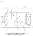
- FIG. 1 is a refrigerant circuit diagram of a hot water system according to a first embodiment of the invention.
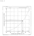
- Fig. 2 is a graph showing the relationship between condensing pressure and condensing temperature of a refrigerating cycle. As shown in Fig.
- the heat-pump hot water system includes a compressor 1, a four-way valve 2 for switching a refrigerant circuit, a plate heat exchanger 10 for exchanging heat between water and a refrigerant, a first electronic expansion valve 6 for controlling the flow rate of the refrigerant to decrease the pressure, a receiver 7 for holding an excess refrigerant, a second electronic expansion valve 8 for controlling the flow rate of the refrigerant to decrease the pressure, and a heat exchanger 9 for exchanging heat between air and the refrigerant, which are connected in order by a pipeline 3 and housed in a hot water system outdoor unit 40.
- a pipe connecting the outlet of the compressor 1 and the four-way valve 2 for switching the refrigerating circuit has pressure detection means Pd for detecting the pressure of the discharged refrigerant.
- the circuit has a structure in which the heat exchanger of the indoor unit of a so-called air conditioner is replaced with the plate heat exchanger 10 for exchanging heat between water and the refrigerant.
- the plate heat exchanger 10 is, however, housed in the hot water system outdoor unit 40, as shown in Fig. 1 .
- the pipeline for connection is therefore very short.
- the refrigerant converted to high-pressure high-temperature gas in the compressor 1 is discharged from the compressor 1 and fed to the four-way valve 2 for switching the circuit.
- the four-way valve 2 is fixed so as to feed the refrigerant discharged from the compressor 1 to the plate heat exchanger 10.
- the refrigerant discharged from the four-way valve 2 is fed to the plate heat exchanger 10.
- the refrigerant fed to the plate heat exchanger 10 exchanges heat with the water passing through a water pipe 50, and is condensed and in the plate heat exchanger 10 to radiate heat.
- the refrigerant is condensed into a high-pressure normal-temperature liquid refrigerant in the plate heat exchanger 10.
- the water obtains heat from the refrigerant to increase its temperature, and is discharged.
- the condensed liquid refrigerant is decreased in pressure by the first electronic expansion valve 6.
- the first electronic expansion valve 6 controls the refrigerant that is condensed by the plate heat exchanger 10 acting as a condenser according to the degree of subcooling.
- the plate heat exchanger 10 has a structure in which the refrigerant and water flow between plates alternately to exchange heat. Therefore, it is impossible to dispose a temperature sensor for sensing the condensing temperature in the middle of the plate heat exchanger 10. Therefore, the pressure detection means Pd is used to detect the pressure of the refrigerant discharged from the compressor 1. That is, the pipe from the compressor 1 to the plate heat exchanger 10 is so short that pressure loss is low, so that the pressure detected by the pressure detection means Pd is substantially equal to the condensing pressure of the refrigerant in the plate heat exchanger 10. As shown in the graph of Fig.
- the condensing temperature (saturation temperature) can be found.
- the saturation temperature T10 of the refrigerant can be calculated from the condensing pressure of the refrigerant in the plate heat exchanger 10.
- the degree of subcooling can be calculated as the difference between the saturation temperature T10 of the refrigerant and the actual condensing temperature of the liquid refrigerant detected by a temperature sensor Tix installed at the outlet of the plate heat exchanger 10.
- the degree of opening of the first electronic expansion valve 6 is decreased so that the liquid of the refrigerant condensed by the plate heat exchanger 10 is increased to thereby increase the degree of subcooling.
- the degree of subcooling is high, the degree of opening of the first electronic expansion valve 6 is increased so that the liquid of the refrigerant condensed by the plate heat exchanger 10 is decreased to thereby decrease the degree of subcooling.
- the degree of opening of the first electronic expansion valve 6 is controlled according to the calculated degree of subcooling to control the degree of subcooling.
- the decompressed refrigerant becomes a low-presser low-temperature liquid refrigerant and enters the receiver 7 connected ahead thereof.
- the receiver 7 holds an excess refrigerant.
- the refrigerant discharged from the receiver 7 is again reduced in pressure by the second electronic expansion valve 8.
- the decompressed refrigerant flows into the heat exchanger 9 that exchanges heat between air and the refrigerant. Since the refrigerant flowing into the heat exchanger 9 is low in temperature, it receives heat from the air to evaporate into a low-pressure low-temperature gas refrigerant. In contrast, the air is cooled to low temperature and blows out.
- the heat exchanger 9 thus acts as an evaporator of the refrigerating cycle.
- the low-pressure low-temperature gas refrigerant discharged from the heat exchanger 9 again flows into the four-way valve 2 for switching the circuit, from which the gas refrigerant is fed to a pipe to the inlet of the compressor 1.
- the low-pressure low-temperature gas refrigerant fed to the inlet of the compressor 1 is compressed in the compressor 1 into a high-pressure high-temperature gas refrigerant, and is discharged from the outlet.
- the second electronic expansion valve 8 is located downstream of the receiver 12.
- the second electronic expansion valve 8 controls the refrigerant to be evaporated in the heat exchanger 9 according to the degree of superheat (degree of discharge superheat).
- the degree of discharge superheat for control is calculated from the difference between the temperature of the refrigerant discharged from the compressor 1 which is detected by temperature detection means Td and the saturation temperature T10 calculated from the condensing pressure of the refrigerant in the plate heat exchanger 10 detected by the pressure detection means Pd.
- the degree of opening of the second electronic expansion valve 8 When the degree of discharge superheat is low, the degree of opening of the second electronic expansion valve 8 is decreased to thereby decrease the amount of the refrigerant evaporated by the heat exchanger 9 to increase the degree of dryness of the refrigerant due to evaporation, thereby increasing the degree of discharge superheat. In contrast, when the degree of discharge superheat is high, the degree of opening of the second electronic expansion valve 8 is increased to thereby increase the amount of the refrigerant evaporated by the heat exchanger 9 to decrease the degree of dryness of the refrigerant due to evaporation, thereby decreasing the degree of discharge superheat.
- the degree of discharge superheat can be controlled by adjusting the degree of opening of the second electronic expansion valve 8 according to the calculated degree of discharge superheat. During heating water, the foregoing cycle is repeated to thereby increase the temperature of the water by heat pump action of transferring the heat obtained from outside air to the water flowing in the water pipe 50.
- a method for controlling the variable-capacity compressor 1 of the hot water system according to the first embodiment of the invention will be described.
- the water flowing through the water pipe 50 gradually increases in temperature while circulating.
- a target condensing temperature depends on a set water temperature because the condensing temperature depends on the temperature of the circulating water.
- the target condensing temperature determined from the set water temperature corresponds to the set temperature of air conditioners.
- the present condensing temperature corresponds to the temperature of the air flowing into the heat exchanger in the indoor unit of air conditioners.
- the compressor 1 is controlled according to the difference between the present condensing temperature and the target condensing temperature determined from the set water temperature.
- the present condensing temperature is calculated as the saturation temperature at the condensing pressure detected by the pressure detection means Pd.
- the speed of operation of the compressor 1 is increased to increase the amount of the refrigerant circulating in the refrigerating cycle so that the actual condensing temperature reaches the target condensing temperature fast, thereby enhancing the performance.
- the speed of operation of the compressor 1 is decreased to reduce the amount of the refrigerant circulating in the refrigerating cycle, thereby reducing the performance.
- the hot water system of the first embodiment of the invention includes the pressure detection means Pd disposed between the outlet of the compressor 1 and the four-way valve 2, for detecting the pressure of the refrigerant discharged from the compressor 1, wherein the operation speed of the compressor 1 is controlled according to the difference between the condensing temperature calculated from the pressure detected by the pressure detection means Pd and a target condensing temperature.
- the hot water system further includes the temperature sensor Tix disposed at the outlet of the plate heat exchanger 10 for detecting the temperature of the liquid refrigerant, wherein the degree of opening of the first electronic expansion valve 6 is adjusted according to the difference between the condensing temperature calculated from the pressure detected by the pressure detection means Pd and the temperature of the liquid refrigerant detected by the temperature sensor Tix.
- the first electronic expansion valve 6 and the variable-capacity compressor 1 can be controlled by a control method similar to that for heating by an air conditioner, ensuring reliability similar to that established by the air conditioner.
- the application of the control established for the air conditioner can reduce the period to develop a control program.
- the use of a refrigerant such as R410A used in the air conditioner allows a control constant for use in driving the actuators to be also applied, providing further reliability and reducing the period for development.
- Second Embodiment Fig. 3 is a refrigerant circuit diagram of a hot water system according to a second embodiment of the invention.
- the heat-pump hot water system according to the second embodiment of the invention includes the compressor 1, the four-way valve 2 for switching the refrigerant circuit, the plate heat exchanger 10 for exchanging heat between water and the refrigerant, the first electronic expansion valve 6 for controlling the flow rate of the refrigerant to decrease the pressure, the receiver 7 for holding an excess refrigerant, the second electronic expansion valve 8 for controlling the flow rate of the refrigerant to decrease the pressure, and the heat exchanger 9 for exchanging heat between air and the refrigerant, which are connected in sequence by a pipeline and housed in the hot water system outdoor unit 40.
- the second embodiment further includes pressure detection means Pc disposed at the pipe connecting the four-way valve 2 and the plate heat exchanger 10, for detecting the condensing pressure of the refrigerant.
- the pressure detection means Pc for detecting the condensing pressure of the refrigerant is disposed at the pipe connecting the four-way valve 2 and the plate heat exchanger 10, the distance between the pressure detection means Pc and the plate heat exchanger 10 is short, so that the pressure loss of the pipe can be minimized. Accordingly, the condensing temperature can be measured more accurately than the first embodiment. Descriptions of the operations of the other components are omitted here because they are the same as those of the first embodiment. [Explanation of Numerals]
Landscapes
- Engineering & Computer Science (AREA)
- Physics & Mathematics (AREA)
- Mechanical Engineering (AREA)
- Thermal Sciences (AREA)
- General Engineering & Computer Science (AREA)
- Chemical & Material Sciences (AREA)
- Combustion & Propulsion (AREA)
- Heat-Pump Type And Storage Water Heaters (AREA)
- Compression-Type Refrigeration Machines With Reversible Cycles (AREA)
Abstract
Description
- The present invention relates to a heat-pump hot water system equipped with a plate heat exchanger.
- A general air conditioner controls a room temperature in such a manner as to calculate the difference between a temperature set by a remote control or the like and an actual room temperature, wherein when the difference is large, the speed of operation of a compressor is increased to enhance the performance of the air conditioner so that the actual room temperature reaches the set temperature as fast as possible.
When the temperature difference is small, the speed of operation of the compressor is decreased to reduce the performance of the air conditioner to save power and prevent the conditioner from being stopped because of overshooting of the room temperature relative to the set temperature.
In a hot water system, a compressor can be controlled by controlling a condensing temperature so as to reach a target condensing temperature in the same manner as the above because the condensing temperature depend on a target hot water temperature. - An example of the conventional air conditioner is disclosed in which the compressor is controlled according to the deviation between the condensing temperature of the refrigerant based on the pressure of the high-pressure refrigerant detected by a high-pressure sensor and a target condensing temperature (refer to Japanese Unexamined Patent Application Publication No.
2002-327949 Fig. 1 )). - Although the conventional air conditioner discloses a technique for controlling a compressor using a high-pressure sensor, it does not refer to application of this technique to a hot water system equipped with a plate heat exchanger.
In a hot water system equipped with a plate heat exchanger, the refrigerant flows in the plate heat exchanger acting as a condenser. Therefore, it is impossible to detect the condensing temperature by temperature detection means mounted on the surface, thus posing the problem that the compressor cannot be controlled according to the condensing temperature of the refrigerant.
The present invention is made to solve the above problems. Accordingly, it is an object of the invention to provide a hot water system equipped with a plate heat exchanger capable of controlling a compressor so that the condensing temperature calculated from the pressure detected by pressure detection means reaches a target condensing temperature and performing subcooling control and superheat control using the calculated condensing temperature. - A hot water system according to a first aspect of the invention includes: a compressor with variable operation capacity; a four-way valve for switching the direction of a refrigerating cycle; a plate heat exchanger for exchanging heat between water and a refrigerant; a first expansion valve for controlling the flow rate of the refrigerant to reduce the pressure; and a heat exchanger for exchanging heat between air and the refrigerant, which are connected in that order by a pipeline to form a refrigerating cycle for circulating the refrigerant, thereby heating water. The hot water system further includes pressure detection means between the outlet of the compressor and the four-way valve, for detecting the pressure of the refrigerant discharged from the compressor, wherein the speed of operation of the compressor is controlled according to the difference between the condensing temperature calculated from the pressure detected by the pressure detection means and a target condensing temperature.
- In the hot water system according to the first aspect of the invention, pressure detection means is disposed between the outlet of the variable-capacity compressor and the four-way valve, for detecting the pressure of the refrigerant discharged from the compressor. The speed of operation of the compressor is controlled according to the difference between the condensing temperature calculated from the pressure detected by the pressure detection means and a target condensing temperature. This offer the advantages of controlling the hot water system by a control method similar to that of the air conditioner, ensuring reliability similar to that of the air conditioner, providing high-reliable control in a short time, and reducing the period to develop a control program.
The invention will now be described by way of non-limiting examples with reference to the accompanying drawings, in which: -
Fig. 1 is a refrigerant circuit diagram of a hot water system according to a first embodiment of the invention; -
Fig. 2 is a graph showing the relationship between the condensing pressure and the condensing temperature of the refrigerating cycle; and -
Fig. 3 is a refrigerant circuit diagram of a hot water system according to a second embodiment of the invention; - First Embodiment
Fig. 1 is a refrigerant circuit diagram of a hot water system according to a first embodiment of the invention.Fig. 2 is a graph showing the relationship between condensing pressure and condensing temperature of a refrigerating cycle.
As shown inFig. 1 , the heat-pump hot water system according to the first embodiment of the invention includes acompressor 1, a four-way valve 2 for switching a refrigerant circuit, aplate heat exchanger 10 for exchanging heat between water and a refrigerant, a firstelectronic expansion valve 6 for controlling the flow rate of the refrigerant to decrease the pressure, areceiver 7 for holding an excess refrigerant, a secondelectronic expansion valve 8 for controlling the flow rate of the refrigerant to decrease the pressure, and aheat exchanger 9 for exchanging heat between air and the refrigerant, which are connected in order by apipeline 3 and housed in a hot water systemoutdoor unit 40.
A pipe connecting the outlet of thecompressor 1 and the four-way valve 2 for switching the refrigerating circuit has pressure detection means Pd for detecting the pressure of the discharged refrigerant.
The circuit has a structure in which the heat exchanger of the indoor unit of a so-called air conditioner is replaced with theplate heat exchanger 10 for exchanging heat between water and the refrigerant. Theplate heat exchanger 10 is, however, housed in the hot water systemoutdoor unit 40, as shown inFig. 1 . The pipeline for connection is therefore very short. - The operation of the hot water system according to the first embodiment will be described.
The refrigerant converted to high-pressure high-temperature gas in thecompressor 1 is discharged from thecompressor 1 and fed to the four-way valve 2 for switching the circuit.
During heating the water, the four-way valve 2 is fixed so as to feed the refrigerant discharged from thecompressor 1 to theplate heat exchanger 10.
The refrigerant discharged from the four-way valve 2 is fed to theplate heat exchanger 10. The refrigerant fed to theplate heat exchanger 10 exchanges heat with the water passing through awater pipe 50, and is condensed and in theplate heat exchanger 10 to radiate heat. The refrigerant is condensed into a high-pressure normal-temperature liquid refrigerant in theplate heat exchanger 10. The water obtains heat from the refrigerant to increase its temperature, and is discharged. The condensed liquid refrigerant is decreased in pressure by the firstelectronic expansion valve 6.
The firstelectronic expansion valve 6 controls the refrigerant that is condensed by theplate heat exchanger 10 acting as a condenser according to the degree of subcooling. - However, the
plate heat exchanger 10 has a structure in which the refrigerant and water flow between plates alternately to exchange heat. Therefore, it is impossible to dispose a temperature sensor for sensing the condensing temperature in the middle of theplate heat exchanger 10.
Therefore, the pressure detection means Pd is used to detect the pressure of the refrigerant discharged from thecompressor 1. That is, the pipe from thecompressor 1 to theplate heat exchanger 10 is so short that pressure loss is low, so that the pressure detected by the pressure detection means Pd is substantially equal to the condensing pressure of the refrigerant in theplate heat exchanger 10. As shown in the graph ofFig. 2 of the relationship between the condensing pressure and the condensing temperature of the refrigerating cycle, there is a certain correlation between the condensing pressure and the condensing temperature (saturation temperature). Therefore, if the condensing pressure is known, the condensing temperature (saturation temperature) can be found. For example, in the case where the refrigerant is R410A., the condensing temperature (saturation temperature) at a condensing pressure of 2.7 MPa is 46°C, as shown inFig. 2 .
Accordingly, the saturation temperature T10 of the refrigerant can be calculated from the condensing pressure of the refrigerant in theplate heat exchanger 10. - The degree of subcooling can be calculated as the difference between the saturation temperature T10 of the refrigerant and the actual condensing temperature of the liquid refrigerant detected by a temperature sensor Tix installed at the outlet of the
plate heat exchanger 10.
When the degree of subcooling is low, the degree of opening of the firstelectronic expansion valve 6 is decreased so that the liquid of the refrigerant condensed by theplate heat exchanger 10 is increased to thereby increase the degree of subcooling. In contrast, when the degree of subcooling is high, the degree of opening of the firstelectronic expansion valve 6 is increased so that the liquid of the refrigerant condensed by theplate heat exchanger 10 is decreased to thereby decrease the degree of subcooling.
Thus the degree of opening of the firstelectronic expansion valve 6 is controlled according to the calculated degree of subcooling to control the degree of subcooling. - The decompressed refrigerant becomes a low-presser low-temperature liquid refrigerant and enters the
receiver 7 connected ahead thereof. Thereceiver 7 holds an excess refrigerant.
The refrigerant discharged from thereceiver 7 is again reduced in pressure by the secondelectronic expansion valve 8. The decompressed refrigerant flows into theheat exchanger 9 that exchanges heat between air and the refrigerant.
Since the refrigerant flowing into theheat exchanger 9 is low in temperature, it receives heat from the air to evaporate into a low-pressure low-temperature gas refrigerant. In contrast, the air is cooled to low temperature and blows out. Theheat exchanger 9 thus acts as an evaporator of the refrigerating cycle.
The low-pressure low-temperature gas refrigerant discharged from theheat exchanger 9 again flows into the four-way valve 2 for switching the circuit, from which the gas refrigerant is fed to a pipe to the inlet of thecompressor 1. The low-pressure low-temperature gas refrigerant fed to the inlet of thecompressor 1 is compressed in thecompressor 1 into a high-pressure high-temperature gas refrigerant, and is discharged from the outlet. - The second
electronic expansion valve 8 is located downstream of the receiver 12. The secondelectronic expansion valve 8 controls the refrigerant to be evaporated in theheat exchanger 9 according to the degree of superheat (degree of discharge superheat).
The degree of discharge superheat for control is calculated from the difference between the temperature of the refrigerant discharged from thecompressor 1 which is detected by temperature detection means Td and the saturation temperature T10 calculated from the condensing pressure of the refrigerant in theplate heat exchanger 10 detected by the pressure detection means Pd.
When the degree of discharge superheat is low, the degree of opening of the secondelectronic expansion valve 8 is decreased to thereby decrease the amount of the refrigerant evaporated by theheat exchanger 9 to increase the degree of dryness of the refrigerant due to evaporation, thereby increasing the degree of discharge superheat. In contrast, when the degree of discharge superheat is high, the degree of opening of the secondelectronic expansion valve 8 is increased to thereby increase the amount of the refrigerant evaporated by theheat exchanger 9 to decrease the degree of dryness of the refrigerant due to evaporation, thereby decreasing the degree of discharge superheat.
Thus, the degree of discharge superheat can be controlled by adjusting the degree of opening of the secondelectronic expansion valve 8 according to the calculated degree of discharge superheat.
During heating water, the foregoing cycle is repeated to thereby increase the temperature of the water by heat pump action of transferring the heat obtained from outside air to the water flowing in thewater pipe 50. - A method for controlling the variable-
capacity compressor 1 of the hot water system according to the first embodiment of the invention will be described.
The water flowing through thewater pipe 50 gradually increases in temperature while circulating. A target condensing temperature depends on a set water temperature because the condensing temperature depends on the temperature of the circulating water.
The target condensing temperature determined from the set water temperature corresponds to the set temperature of air conditioners.
The present condensing temperature corresponds to the temperature of the air flowing into the heat exchanger in the indoor unit of air conditioners. Thus, thecompressor 1 is controlled according to the difference between the present condensing temperature and the target condensing temperature determined from the set water temperature.
The present condensing temperature is calculated as the saturation temperature at the condensing pressure detected by the pressure detection means Pd.
When the present condensing temperature is lower than the target condensing temperature determined from the set water temperature and the difference therebetween is large, the speed of operation of thecompressor 1 is increased to increase the amount of the refrigerant circulating in the refrigerating cycle so that the actual condensing temperature reaches the target condensing temperature fast, thereby enhancing the performance.
In contrast, when the present condensing temperature is lower than the target condensing temperature determined from the set water temperature and the difference therebetween is small, or when the present condensing temperature is higher than the target condensing temperature, the speed of operation of thecompressor 1 is decreased to reduce the amount of the refrigerant circulating in the refrigerating cycle, thereby reducing the performance. - As described above, the hot water system of the first embodiment of the invention includes the pressure detection means Pd disposed between the outlet of the
compressor 1 and the four-way valve 2, for detecting the pressure of the refrigerant discharged from thecompressor 1, wherein the operation speed of thecompressor 1 is controlled according to the difference between the condensing temperature calculated from the pressure detected by the pressure detection means Pd and a target condensing temperature. The hot water system further includes the temperature sensor Tix disposed at the outlet of theplate heat exchanger 10 for detecting the temperature of the liquid refrigerant, wherein the degree of opening of the firstelectronic expansion valve 6 is adjusted according to the difference between the condensing temperature calculated from the pressure detected by the pressure detection means Pd and the temperature of the liquid refrigerant detected by the temperature sensor Tix. Therefore, even with theplate heat exchanger 10, the firstelectronic expansion valve 6 and the variable-capacity compressor 1 can be controlled by a control method similar to that for heating by an air conditioner, ensuring reliability similar to that established by the air conditioner. The application of the control established for the air conditioner can reduce the period to develop a control program.
Moreover, the use of a refrigerant such as R410A used in the air conditioner allows a control constant for use in driving the actuators to be also applied, providing further reliability and reducing the period for development. - Second Embodiment
Fig. 3 is a refrigerant circuit diagram of a hot water system according to a second embodiment of the invention.
As shown inFig. 3 , the heat-pump hot water system according to the second embodiment of the invention includes thecompressor 1, the four-way valve 2 for switching the refrigerant circuit, theplate heat exchanger 10 for exchanging heat between water and the refrigerant, the firstelectronic expansion valve 6 for controlling the flow rate of the refrigerant to decrease the pressure, thereceiver 7 for holding an excess refrigerant, the secondelectronic expansion valve 8 for controlling the flow rate of the refrigerant to decrease the pressure, and theheat exchanger 9 for exchanging heat between air and the refrigerant, which are connected in sequence by a pipeline and housed in the hot water systemoutdoor unit 40. - The second embodiment further includes pressure detection means Pc disposed at the pipe connecting the four-
way valve 2 and theplate heat exchanger 10, for detecting the condensing pressure of the refrigerant.
In the case where the pressure detection means Pc for detecting the condensing pressure of the refrigerant is disposed at the pipe connecting the four-way valve 2 and theplate heat exchanger 10, the distance between the pressure detection means Pc and theplate heat exchanger 10 is short, so that the pressure loss of the pipe can be minimized. Accordingly, the condensing temperature can be measured more accurately than the first embodiment.
Descriptions of the operations of the other components are omitted here because they are the same as those of the first embodiment.
[Explanation of Numerals] -
- 1: COMPRESSOR
- 2: FOUR-WAY VALVE
- 3: PIPELINE
- 6: FIRST ELECTRONIC EXPANSION VALVE
- 7: RECEIVER
- 8: SECOND ELECTRONIC EXPANSION VALVE
- 9: HEAT EXCHANGER
- 10: PLATE HEAT EXCHANGER
- 40: HOT WATER SYSTEM OUTDOOR UNIT
- 50: WATER PIPE
- Td: TEMPERATURE SENSOR FOR DETECTING DISCHARGED REFRIGERANT TEMPERATURE
- Tix: TEMPERATURE SENSOR FOR DETECTING LIQUID REFRIGERANT TEMPERATURE
- Pd: PRESSURE DETECTION MEANS FOR DETECTING DISCHARGED REFRIGERANT PRESSURE
Claims (7)
- A hot water system comprising:a compressor (1) with variable operation capacity;a four-way valve (2) for switching the direction of a refrigerating cycle;a plate heat exchanger (10) for exchanging heat between water and a refrigerant;a first expansion valve (6) for controlling the flow rate of the refrigerant to reduce the pressure; anda heat exchanger (9) for exchanging heat between air and the refrigerant, which are connected in that order by a pipeline (3) to form a refrigerating cycle for circulating the refrigerant, thereby heating water;the hot water system further comprising;pressure detection means (Pd) disposed between the outlet of the compressor (1) and the four-way valve (2), for detecting the pressure of the refrigerant discharged from the compressor (1), whereinthe speed of operation of the compressor (1) is controlled according to the difference between the condensing temperature calculated from the pressure detected by the pressure detection means (Pd) and a target condensing temperature.
- The hot water system according to Claim 1, further comprising;
temperature detection means (Tix) for detecting the temperature of a liquid refrigerant disposed at the outlet of the plate heat exchanger (10), wherein
the degree of opening of the first expansion valve (6) is controlled according to the difference between the condensing temperature calculated from the pressure detected by the pressure detection means (Pd) and the temperature of the liquid refrigerant detected by the temperature detection means (Tix). - The hot water system according to Claim 1, further comprising:a receiver (7) disposed between the first expansion valve (6) and the heat exchanger.(9);a second expansion valve (8) disposed between the receiver (7) and the heat exchanger (9); andtemperature detection means (Td) for detecting the temperature of the discharged refrigerant, disposed at the outlet of the compressor (1), whereinthe degree of opening of the second expansion valve (8) is controlled according to the difference between the condensing temperature calculated from the pressure detected by the pressure detection means (Pd) and the temperature of the liquid refrigerant detected by the temperature detection means (Td).
- A hot water system comprising:a compressor (1) with variable operation capacity;a four-way valve (2) for switching the direction of the refrigerating cycle;a plate heat exchanger (10) for exchanging heat between water and the refrigerant;a first expansion valve (6) for controlling the flow rate of the refrigerant to reduce the pressure; anda heat exchanger (9) for exchanging heat between air and the refrigerant, which are connected in that order by a pipeline to form a refrigerating cycle for circulating the refrigerant, thereby heating water;the hot water system further comprising;pressure detection means (Pc) disposed between the four-way valve (2) and the plate heat exchanger (10), for detecting the condensing pressure of the refrigerant, whereinthe speed of operation of the compressor (1) is controlled according to the difference between the condensing temperature calculated from the pressure detected by the pressure detection means (Pc) and a target condensing temperature.
- The hot water system according to Claim 4, further comprising:temperature detection means (Tix) for detecting the temperature of a liquid refrigerant disposed at the outlet of the plate heat exchanger (10), whereinthe degree of opening of the first expansion valve (6) is controlled according to the difference between the condensing temperature calculated from the pressure detected by the pressure detection means (Pc) and the temperature of the liquid refrigerant detected by the temperature detection means (Tix).
- The hot water system according to Claim 4, further comprising:a receiver (7) disposed between the first expansion valve (6) and the heat exchanger (9);a second expansion valve (8) disposed between the receiver (7) and the heat exchanger (9); andtemperature detection means (Td) for detecting the temperature of the discharged refrigerant, disposed at the outlet of the compressor (1), whereinthe degree of opening of the.second expansion valve (8) is controlled according to the difference between the condensing temperature calculated from the pressure detected by the pressure detection means (Pc) and the temperature of the liquid refrigerant detected by the temperature detection means (Td).
- The hot water system according to any of Claims 1 to 6, wherein the refrigerant used in the refrigerating cycle is R410A.
Applications Claiming Priority (1)
| Application Number | Priority Date | Filing Date | Title |
|---|---|---|---|
| JP2007070995A JP2008232508A (en) | 2007-03-19 | 2007-03-19 | Water heater |
Publications (3)
| Publication Number | Publication Date |
|---|---|
| EP1972871A2 true EP1972871A2 (en) | 2008-09-24 |
| EP1972871A3 EP1972871A3 (en) | 2015-09-02 |
| EP1972871B1 EP1972871B1 (en) | 2016-09-28 |
Family
ID=39591412
Family Applications (1)
| Application Number | Title | Priority Date | Filing Date |
|---|---|---|---|
| EP07254438.0A Not-in-force EP1972871B1 (en) | 2007-03-19 | 2007-11-13 | Hot water system |
Country Status (2)
| Country | Link |
|---|---|
| EP (1) | EP1972871B1 (en) |
| JP (1) | JP2008232508A (en) |
Cited By (16)
| Publication number | Priority date | Publication date | Assignee | Title |
|---|---|---|---|---|
| EP2306124A1 (en) * | 2009-09-28 | 2011-04-06 | Fujitsu General Limited | Heat pump apparatus |
| EP2508820A1 (en) * | 2011-04-07 | 2012-10-10 | LG Electronics, Inc. | Air conditioner |
| GB2485623B (en) * | 2011-02-11 | 2012-10-17 | Esg Pool Ventilation Ltd | Heating and/or cooling system and related methods |
| US20130180274A1 (en) * | 2010-10-29 | 2013-07-18 | Mitsubishi Electric Corporation | Refrigeration cycle apparatus and refrigeration cycle control method |
| EP2639516A3 (en) * | 2012-03-12 | 2014-03-26 | Panasonic Corporation | Heat pump hydronic heater |
| CN103808012A (en) * | 2012-11-13 | 2014-05-21 | 珠海格力电器股份有限公司 | variable-frequency water heater and control method thereof |
| EP2653805A4 (en) * | 2010-12-15 | 2014-06-04 | Mitsubishi Electric Corp | COMBINED SYSTEM OF AIR CONDITIONING AND HOT WATER DISTRIBUTION |
| US8984901B2 (en) | 2009-02-24 | 2015-03-24 | Daikin Industries, Ltd. | Heat pump system |
| EP2813784A4 (en) * | 2011-12-22 | 2016-04-06 | Mitsubishi Electric Corp | AIR CONDITIONER |
| CN106766365A (en) * | 2016-11-28 | 2017-05-31 | 广东美的暖通设备有限公司 | Frequency conversion air-cooled heat pump water chiller-heater system and its control method and air-conditioning |
| CN107051963A (en) * | 2017-06-06 | 2017-08-18 | 扬州金威环保科技有限公司 | A kind of cleaning fluid temperature control system based on classification cycle principle of heating |
| CN107606834A (en) * | 2017-09-12 | 2018-01-19 | 广东美的暖通设备有限公司 | The control method and multiple on-line system of multiple on-line system |
| EP2459945B1 (en) * | 2009-07-31 | 2018-05-02 | Johnson Controls Technology Company | Refrigeration system and operating method |
| WO2018176283A1 (en) * | 2017-03-29 | 2018-10-04 | 广东美的制冷设备有限公司 | Air conditioner |
| EP3236174A4 (en) * | 2014-11-27 | 2018-10-24 | Mitsubishi Electric Corporation | Combined air conditioning and hot-water supply system |
| EP4477973A4 (en) * | 2022-03-15 | 2025-06-25 | Samsung Electronics Co., Ltd. | HEAT PUMP SYSTEM AND CONTROL METHODS THEREFOR |
Families Citing this family (7)
| Publication number | Priority date | Publication date | Assignee | Title |
|---|---|---|---|---|
| JP4854779B2 (en) * | 2009-12-09 | 2012-01-18 | シャープ株式会社 | Air conditioner, expansion valve opening control method and program |
| JP5913402B2 (en) * | 2014-02-28 | 2016-04-27 | ダイキン工業株式会社 | Heat pump system |
| JP6387246B2 (en) * | 2014-05-19 | 2018-09-05 | リンナイ株式会社 | Heat pump heating device |
| KR102181204B1 (en) * | 2014-06-09 | 2020-11-20 | 엘지전자 주식회사 | Refrigerant system |
| JP5921777B1 (en) * | 2014-09-22 | 2016-05-24 | 三菱電機株式会社 | Refrigeration cycle equipment |
| JPWO2016185689A1 (en) * | 2015-05-20 | 2018-03-08 | パナソニックIpマネジメント株式会社 | Air conditioning and hot water supply system |
| CN111578483B (en) * | 2020-04-21 | 2021-12-21 | 重庆海尔空调器有限公司 | Method and device for preventing condensation of air conditioner panel and air conditioner |
Citations (1)
| Publication number | Priority date | Publication date | Assignee | Title |
|---|---|---|---|---|
| JP2002327949A (en) | 2001-04-27 | 2002-11-15 | Daikin Ind Ltd | Air conditioner |
Family Cites Families (14)
| Publication number | Priority date | Publication date | Assignee | Title |
|---|---|---|---|---|
| DE8119446U1 (en) * | 1981-07-03 | 1981-11-05 | Alcoa Deutschland Gmbh Verpackungswerke, 6520 Worms | Kit for a cap lock |
| JP3655681B2 (en) * | 1995-06-23 | 2005-06-02 | 三菱電機株式会社 | Refrigerant circulation system |
| JP3632402B2 (en) * | 1997-10-22 | 2005-03-23 | 松下電器産業株式会社 | Heat pump water heater |
| JPH11270919A (en) * | 1998-03-25 | 1999-10-05 | Mitsubishi Electric Corp | Refrigeration cycle device |
| JP2000104940A (en) * | 1998-09-28 | 2000-04-11 | Kyushu Electric Power Co Inc | Heat pump hot water supply system |
| JP2000111213A (en) * | 1998-10-06 | 2000-04-18 | Daikin Ind Ltd | Refrigeration equipment |
| JP2001263831A (en) * | 2000-03-24 | 2001-09-26 | Mitsubishi Electric Corp | Refrigeration cycle device |
| JP4169454B2 (en) * | 2000-04-12 | 2008-10-22 | 大阪瓦斯株式会社 | Hot water storage hot water source |
| JP2001304703A (en) * | 2000-04-18 | 2001-10-31 | Matsushita Electric Ind Co Ltd | Refrigeration cycle device |
| JP2002089958A (en) * | 2000-09-20 | 2002-03-27 | Toshiba Kyaria Kk | Heat pump type hot water supply system |
| JP4349851B2 (en) * | 2003-06-24 | 2009-10-21 | 日立アプライアンス株式会社 | Refrigeration cycle equipment |
| JP3843978B2 (en) * | 2003-11-06 | 2006-11-08 | 松下電器産業株式会社 | Heat pump water heater |
| GB2414289A (en) * | 2004-05-19 | 2005-11-23 | Asker Barum Kuldeteknikk A S | A heat pump installation |
| US7302811B2 (en) * | 2004-11-23 | 2007-12-04 | Parker Hannifin Corporation | Fluid expansion-distribution assembly |
-
2007
- 2007-03-19 JP JP2007070995A patent/JP2008232508A/en active Pending
- 2007-11-13 EP EP07254438.0A patent/EP1972871B1/en not_active Not-in-force
Patent Citations (1)
| Publication number | Priority date | Publication date | Assignee | Title |
|---|---|---|---|---|
| JP2002327949A (en) | 2001-04-27 | 2002-11-15 | Daikin Ind Ltd | Air conditioner |
Cited By (24)
| Publication number | Priority date | Publication date | Assignee | Title |
|---|---|---|---|---|
| US8984901B2 (en) | 2009-02-24 | 2015-03-24 | Daikin Industries, Ltd. | Heat pump system |
| EP2459945B1 (en) * | 2009-07-31 | 2018-05-02 | Johnson Controls Technology Company | Refrigeration system and operating method |
| US8978402B2 (en) | 2009-09-28 | 2015-03-17 | Fujitsu General Limited | Heat pump apparatus |
| EP2306124A1 (en) * | 2009-09-28 | 2011-04-06 | Fujitsu General Limited | Heat pump apparatus |
| CN102032704A (en) * | 2009-09-28 | 2011-04-27 | 富士通将军股份有限公司 | Heat pump device |
| AU2010224438B2 (en) * | 2009-09-28 | 2015-08-20 | Fujitsu General Limited | Heat pump apparatus |
| US20130180274A1 (en) * | 2010-10-29 | 2013-07-18 | Mitsubishi Electric Corporation | Refrigeration cycle apparatus and refrigeration cycle control method |
| EP2653805A4 (en) * | 2010-12-15 | 2014-06-04 | Mitsubishi Electric Corp | COMBINED SYSTEM OF AIR CONDITIONING AND HOT WATER DISTRIBUTION |
| US9625187B2 (en) | 2010-12-15 | 2017-04-18 | Mitsubishi Electric Corporation | Combined air-conditioning and hot-water supply system |
| GB2485623B (en) * | 2011-02-11 | 2012-10-17 | Esg Pool Ventilation Ltd | Heating and/or cooling system and related methods |
| US9328931B2 (en) | 2011-02-11 | 2016-05-03 | Esg Pool Ventilation Ltd | Heating and/or cooling system for maintaining an environment at a desired temperature |
| CN102734869A (en) * | 2011-04-07 | 2012-10-17 | Lg电子株式会社 | Air conditioner |
| EP2508820A1 (en) * | 2011-04-07 | 2012-10-10 | LG Electronics, Inc. | Air conditioner |
| EP2813784A4 (en) * | 2011-12-22 | 2016-04-06 | Mitsubishi Electric Corp | AIR CONDITIONER |
| EP2639516A3 (en) * | 2012-03-12 | 2014-03-26 | Panasonic Corporation | Heat pump hydronic heater |
| CN103808012B (en) * | 2012-11-13 | 2016-06-08 | 珠海格力电器股份有限公司 | variable-frequency water heater and control method thereof |
| CN103808012A (en) * | 2012-11-13 | 2014-05-21 | 珠海格力电器股份有限公司 | variable-frequency water heater and control method thereof |
| EP3236174A4 (en) * | 2014-11-27 | 2018-10-24 | Mitsubishi Electric Corporation | Combined air conditioning and hot-water supply system |
| CN106766365A (en) * | 2016-11-28 | 2017-05-31 | 广东美的暖通设备有限公司 | Frequency conversion air-cooled heat pump water chiller-heater system and its control method and air-conditioning |
| WO2018176283A1 (en) * | 2017-03-29 | 2018-10-04 | 广东美的制冷设备有限公司 | Air conditioner |
| CN107051963A (en) * | 2017-06-06 | 2017-08-18 | 扬州金威环保科技有限公司 | A kind of cleaning fluid temperature control system based on classification cycle principle of heating |
| CN107051963B (en) * | 2017-06-06 | 2022-08-12 | 扬州金威环保科技有限公司 | Cleaning fluid temperature control system based on hierarchical circulation heating principle |
| CN107606834A (en) * | 2017-09-12 | 2018-01-19 | 广东美的暖通设备有限公司 | The control method and multiple on-line system of multiple on-line system |
| EP4477973A4 (en) * | 2022-03-15 | 2025-06-25 | Samsung Electronics Co., Ltd. | HEAT PUMP SYSTEM AND CONTROL METHODS THEREFOR |
Also Published As
| Publication number | Publication date |
|---|---|
| EP1972871A3 (en) | 2015-09-02 |
| JP2008232508A (en) | 2008-10-02 |
| EP1972871B1 (en) | 2016-09-28 |
Similar Documents
| Publication | Publication Date | Title |
|---|---|---|
| EP1972871B1 (en) | Hot water system | |
| US7856836B2 (en) | Refrigerating air conditioning system | |
| EP2416093B1 (en) | Combined system of air conditioning device and hot-water supply device | |
| JP4931848B2 (en) | Heat pump type outdoor unit for hot water supply | |
| US8104299B2 (en) | Air conditioner | |
| CN101821560B (en) | air conditioner | |
| EP3190357B1 (en) | Air conditioner | |
| US8020395B2 (en) | Air conditioning apparatus | |
| JP5673738B2 (en) | Air conditioner | |
| US20160097568A1 (en) | Air-conditioning apparatus | |
| US12235028B2 (en) | Refrigerant leakage determination system | |
| CN100504239C (en) | Refrigeration device and air conditioner using it | |
| EP2261578A1 (en) | Refrigeration device | |
| EP2196746B1 (en) | Refrigeration apparatus | |
| US7171818B2 (en) | System and method for controlling temperature of refrigerant in air conditioner | |
| JP2005121361A (en) | Controller and method for controlling degree of superheat in heat pump system | |
| EP3312528B1 (en) | Air conditioner | |
| US10527334B2 (en) | Refrigeration system | |
| EP4227610A1 (en) | Refrigeration system and the control method thereof | |
| JP5855284B2 (en) | Air conditioner | |
| JP2011196684A (en) | Heat pump device and outdoor unit of the heat pump device | |
| US7921670B2 (en) | Refrigeration apparatus | |
| JP4462436B2 (en) | Refrigeration equipment | |
| KR101504003B1 (en) | Heat pump type air conditioner | |
| JPH10300255A (en) | Air conditioner |
Legal Events
| Date | Code | Title | Description |
|---|---|---|---|
| PUAI | Public reference made under article 153(3) epc to a published international application that has entered the european phase |
Free format text: ORIGINAL CODE: 0009012 |
|
| AK | Designated contracting states |
Kind code of ref document: A2 Designated state(s): AT BE BG CH CY CZ DE DK EE ES FI FR GB GR HU IE IS IT LI LT LU LV MC MT NL PL PT RO SE SI SK TR |
|
| AX | Request for extension of the european patent |
Extension state: AL BA HR MK RS |
|
| RIC1 | Information provided on ipc code assigned before grant |
Ipc: F25B 49/02 20060101AFI20150227BHEP Ipc: F25B 13/00 20060101ALN20150227BHEP |
|
| PUAL | Search report despatched |
Free format text: ORIGINAL CODE: 0009013 |
|
| AK | Designated contracting states |
Kind code of ref document: A3 Designated state(s): AT BE BG CH CY CZ DE DK EE ES FI FR GB GR HU IE IS IT LI LT LU LV MC MT NL PL PT RO SE SI SK TR |
|
| AX | Request for extension of the european patent |
Extension state: AL BA HR MK RS |
|
| RIC1 | Information provided on ipc code assigned before grant |
Ipc: F25B 13/00 20060101ALN20150728BHEP Ipc: F25B 49/02 20060101AFI20150728BHEP |
|
| 17P | Request for examination filed |
Effective date: 20151203 |
|
| RBV | Designated contracting states (corrected) |
Designated state(s): AT BE BG CH CY CZ DE DK EE ES FI FR GB GR HU IE IS IT LI LT LU LV MC MT NL PL PT RO SE SI SK TR |
|
| RIC1 | Information provided on ipc code assigned before grant |
Ipc: F25B 13/00 20060101ALN20160211BHEP Ipc: F25B 49/02 20060101AFI20160211BHEP |
|
| GRAP | Despatch of communication of intention to grant a patent |
Free format text: ORIGINAL CODE: EPIDOSNIGR1 |
|
| INTG | Intention to grant announced |
Effective date: 20160322 |
|
| AKX | Designation fees paid |
Designated state(s): FR GB |
|
| AXX | Extension fees paid |
Extension state: AL Extension state: BA Extension state: RS Extension state: HR Extension state: MK |
|
| REG | Reference to a national code |
Ref country code: DE Ref legal event code: R108 |
|
| GRAS | Grant fee paid |
Free format text: ORIGINAL CODE: EPIDOSNIGR3 |
|
| GRAA | (expected) grant |
Free format text: ORIGINAL CODE: 0009210 |
|
| AK | Designated contracting states |
Kind code of ref document: B1 Designated state(s): FR GB |
|
| REG | Reference to a national code |
Ref country code: GB Ref legal event code: FG4D |
|
| REG | Reference to a national code |
Ref country code: FR Ref legal event code: PLFP Year of fee payment: 10 |
|
| PLBE | No opposition filed within time limit |
Free format text: ORIGINAL CODE: 0009261 |
|
| STAA | Information on the status of an ep patent application or granted ep patent |
Free format text: STATUS: NO OPPOSITION FILED WITHIN TIME LIMIT |
|
| 26N | No opposition filed |
Effective date: 20170629 |
|
| REG | Reference to a national code |
Ref country code: FR Ref legal event code: PLFP Year of fee payment: 11 |
|
| REG | Reference to a national code |
Ref country code: FR Ref legal event code: PLFP Year of fee payment: 12 |
|
| REG | Reference to a national code |
Ref country code: GB Ref legal event code: 746 Effective date: 20190122 |
|
| PGFP | Annual fee paid to national office [announced via postgrant information from national office to epo] |
Ref country code: GB Payment date: 20191115 Year of fee payment: 13 |
|
| PGFP | Annual fee paid to national office [announced via postgrant information from national office to epo] |
Ref country code: FR Payment date: 20201013 Year of fee payment: 14 |
|
| GBPC | Gb: european patent ceased through non-payment of renewal fee |
Effective date: 20201113 |
|
| PG25 | Lapsed in a contracting state [announced via postgrant information from national office to epo] |
Ref country code: GB Free format text: LAPSE BECAUSE OF NON-PAYMENT OF DUE FEES Effective date: 20201113 |
|
| PG25 | Lapsed in a contracting state [announced via postgrant information from national office to epo] |
Ref country code: FR Free format text: LAPSE BECAUSE OF NON-PAYMENT OF DUE FEES Effective date: 20211130 |