EP1972802B1 - Inclined roller bearing - Google Patents
Inclined roller bearing Download PDFInfo
- Publication number
- EP1972802B1 EP1972802B1 EP20080152139 EP08152139A EP1972802B1 EP 1972802 B1 EP1972802 B1 EP 1972802B1 EP 20080152139 EP20080152139 EP 20080152139 EP 08152139 A EP08152139 A EP 08152139A EP 1972802 B1 EP1972802 B1 EP 1972802B1
- Authority
- EP
- European Patent Office
- Prior art keywords
- bearing
- filling
- double
- roller bearing
- rolling bodies
- Prior art date
- Legal status (The legal status is an assumption and is not a legal conclusion. Google has not performed a legal analysis and makes no representation as to the accuracy of the status listed.)
- Active
Links
- 238000005096 rolling process Methods 0.000 claims description 40
- 239000000463 material Substances 0.000 claims description 2
- 238000007789 sealing Methods 0.000 claims description 2
- 239000000945 filler Substances 0.000 description 7
- 239000000314 lubricant Substances 0.000 description 3
- 230000000295 complement effect Effects 0.000 description 2
- 238000005461 lubrication Methods 0.000 description 2
- 238000004519 manufacturing process Methods 0.000 description 2
- 229910000831 Steel Inorganic materials 0.000 description 1
- 238000005520 cutting process Methods 0.000 description 1
- 238000005516 engineering process Methods 0.000 description 1
- 238000005429 filling process Methods 0.000 description 1
- 239000000203 mixture Substances 0.000 description 1
- 230000035939 shock Effects 0.000 description 1
- 239000010959 steel Substances 0.000 description 1
Images

Classifications
-
- F—MECHANICAL ENGINEERING; LIGHTING; HEATING; WEAPONS; BLASTING
- F16—ENGINEERING ELEMENTS AND UNITS; GENERAL MEASURES FOR PRODUCING AND MAINTAINING EFFECTIVE FUNCTIONING OF MACHINES OR INSTALLATIONS; THERMAL INSULATION IN GENERAL
- F16C—SHAFTS; FLEXIBLE SHAFTS; ELEMENTS OR CRANKSHAFT MECHANISMS; ROTARY BODIES OTHER THAN GEARING ELEMENTS; BEARINGS
- F16C19/00—Bearings with rolling contact, for exclusively rotary movement
- F16C19/22—Bearings with rolling contact, for exclusively rotary movement with bearing rollers essentially of the same size in one or more circular rows, e.g. needle bearings
- F16C19/34—Bearings with rolling contact, for exclusively rotary movement with bearing rollers essentially of the same size in one or more circular rows, e.g. needle bearings for both radial and axial load
- F16C19/38—Bearings with rolling contact, for exclusively rotary movement with bearing rollers essentially of the same size in one or more circular rows, e.g. needle bearings for both radial and axial load with two or more rows of rollers
-
- F—MECHANICAL ENGINEERING; LIGHTING; HEATING; WEAPONS; BLASTING
- F16—ENGINEERING ELEMENTS AND UNITS; GENERAL MEASURES FOR PRODUCING AND MAINTAINING EFFECTIVE FUNCTIONING OF MACHINES OR INSTALLATIONS; THERMAL INSULATION IN GENERAL
- F16C—SHAFTS; FLEXIBLE SHAFTS; ELEMENTS OR CRANKSHAFT MECHANISMS; ROTARY BODIES OTHER THAN GEARING ELEMENTS; BEARINGS
- F16C43/00—Assembling bearings
- F16C43/04—Assembling rolling-contact bearings
- F16C43/06—Placing rolling bodies in cages or bearings
-
- F—MECHANICAL ENGINEERING; LIGHTING; HEATING; WEAPONS; BLASTING
- F16—ENGINEERING ELEMENTS AND UNITS; GENERAL MEASURES FOR PRODUCING AND MAINTAINING EFFECTIVE FUNCTIONING OF MACHINES OR INSTALLATIONS; THERMAL INSULATION IN GENERAL
- F16C—SHAFTS; FLEXIBLE SHAFTS; ELEMENTS OR CRANKSHAFT MECHANISMS; ROTARY BODIES OTHER THAN GEARING ELEMENTS; BEARINGS
- F16C2240/00—Specified values or numerical ranges of parameters; Relations between them
- F16C2240/40—Linear dimensions, e.g. length, radius, thickness, gap
- F16C2240/70—Diameters; Radii
- F16C2240/80—Pitch circle diameters [PCD]
- F16C2240/82—Degree of filling, i.e. sum of diameters of rolling elements in relation to PCD
- F16C2240/84—Degree of filling, i.e. sum of diameters of rolling elements in relation to PCD with full complement of balls or rollers, i.e. sum of clearances less than diameter of one rolling element
Definitions
- the invention relates to a double-row tapered roller bearing, which consists of an outer bearing ring and an inner bearing ring and a number between the bearing rings in two rows of juxtaposed cylindrical rolling elements, which are employed to each other in O arrangement and roll on tracks, which are inclined at an angle extend to a bearing axis, wherein each row of rolling elements is provided with a lying outside the raceway filling opening whose central axis is an extension of axes of rotation of the rolling elements and both filling openings are closed after filling of the rolling elements by a Standstopfen.
- Double-row tapered roller bearings are always used when two-row angular contact ball bearings or cross-roller bearings can no longer transmit the necessary forces (service life) or moments (tilting rigidity) in the same space.
- a typical embodiment of such bearings is shown in the SKF catalog 3135 T "RKS pivot bearing", page 96.
- These double-row pivot bearings have one-piece rings. The roles From a rolling bearing steel are inserted through a common filling opening in a bearing ring in the camp, the filler opening is to close after the introduction of the rolling elements with a stopper.
- the filling opening is part of the career. This has the consequence that the filling opening to be closed filling plug is just as expensive to handle as the career. This filler plug must therefore also be hardened and ground. In addition, such a filling plug forms a contact edge for the rolling elements, so that noises or vibrations are preprogrammed. For certain applications, for example in medical technology, but very low noise and low-impact bearings are an absolute requirement. Another disadvantage is due to the fact that the filling opening to be closed filling plug is just as expensive to handle as the career. This filler plug must therefore also be hardened and ground. In addition, such a filling plug forms a contact edge for the rolling elements, so that noises or vibrations are preprogrammed. For certain applications, for example in medical technology, but very low noise and low-impact bearings are an absolute requirement. Another disadvantage is due to the fact that the filling opening to be closed filling plug is just as expensive to handle as the career. This filler plug must therefore also be hardened and ground. In addition, such a filling plug forms
- Race closing filler plug must be secured, which in turn causes a relatively large radial expansion of the bearing ring. It is also disadvantageous that the filling plug limits the distance between the two raceways relative to one another, since the latter has to be widened the farther the raceways are in the axial direction from one another.
- a double-row tapered roller bearing with the features of the preamble of claim 1, for example, from US 3,948,578 A known.
- This bearing comprises two respective one-piece bearing rings, each bearing ring having both loaded, functioning as roller bearing raceways surface areas, as well as non-loaded surface areas.
- one of the bearing rings has a filling opening in a non-loaded surface area.
- Another double-row tapered roller bearing is from the US 2,055,714 A known. Also in this case filling openings are provided for filling with cylindrical rolling elements. The filling openings are formed as concentric to the axis of symmetry of a rolling body channels.
- the object of the invention is therefore to further develop a generic tapered roller bearing in such a way that, on the one hand, the running behavior is improved and, on the other hand, further miniaturization of the bearing is possible.
- each rolling element row is provided with a lying outside the raceway filling opening whose central axis is an extension of axes of rotation of the rolling elements and both filling openings after filling of the rolling elements a filling plug are closed.
- the decisive advantage of the solution according to the invention is that the filling plugs are no longer part of the raceways. As a result, the production costs are significantly reduced, since the filler used must have no career qualities. Also, the running properties of the bearing are improved because the tracks are no longer interrupted and therefore the camp works very shock and quiet. By eliminating the fixation of the Grestopfens in one of the bearing rings this can be reduced in its radial extent, which is particularly advantageous in a lack of space. It is also advantageous that, in contrast to the prior art broadening the axial distance between the two tracks from each other without problems is possible, since this has no influence on the filling plug, since this, as already stated, is no longer part of the raceways.
- the filling plug is a plastic ball which is pressed with excess into the filling opening.
- plastic balls are available as a cheap purchased part in a variety of material composition and size ratios on the market and therefore particularly cost-effective.
- the closure of the filling holes through the plugs ensures that on the one hand no dirt can penetrate from the outside to the inside of the bearing and that on the other hand no lubricant can get out of the bearing from the inside out.
- the filling stopper should be designed as a chipless manufactured centering, which consists of a sleeve whose bottom receives a ball race whose centrally arranged space receives a single, larger diameter bearing ball.
- this type of filler plug is relatively expensive to manufacture, but allows a rolling movement between filler and rolling elements in the filling opening.
- the rolling elements can be arranged either full complement or spaced apart by an intermediate piece in the circumferential direction.
- the full complement arrangement of the rolling elements allows a particularly high load capacity, while a particularly smooth running of the bearing is realized by the imported intermediate pieces.
- the filling opening should be slightly larger in diameter than the diameter of the rolling elements.
- one of the bearing rings should be provided with a sealing element which bears against the associated other bearing ring under prestress.
- FIG. 5 The there illustrated double row tapered roller bearing consists of the outer bearing ring 1 and the inner bearing ring 2, which are arranged concentrically around the bearing axis 6 into one another. Between two bearing rings 1, 2 roll cylindrical rolling elements 3, 4 from. The filling of the bearing with the rolling elements 3, 4 takes place in such a way that they are fed to the bearing via an unspecified filling opening in the inner bearing ring 2. After this Filling the filling opening is closed with the filling plug 7, which in turn must be secured in the inner bearing ring 2 by means of the fastening screw 5. It is obvious that with an increasing distance L in the axial direction of the two rows of rolling elements 3, 4 from each other, according to FIG. 5 is defined with the length L, the filler 7 must adapt accordingly. This is where the invention begins, with which a simplification of such a bearing is to be achieved.
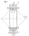
- the tapered roller bearing 8 of the invention consists of the outer bearing ring 9 and the inner bearing ring 10 which are concentric with each other and define a free space between them, in which the cylindrical rolling elements 11, 12 full roll, ie, are arranged without a cage.
- the outer bearing ring 9 is integrally formed and has in its central part on the triangular portion 13 which carries the outer raceways 14, 15, which are arranged at an angle ⁇ inclined to the bearing axis 16.
- the middle part of the outer bearing ring 9 is provided on its lateral surface with the circumferential lubrication groove 17, branches off from the at least one radial lubricant passage bore 18.
- both rows of rolling elements 11, 12 are guided on their outer end faces by a fixed board 19, 20, which are formed by the outer bearing ring 9.
- Both ribs 19, 20 extend in the embodiment over the entire end face of the cylindrical rolling elements 11, 12 and thus ensure their exact guidance.
- the inner bearing ring 10 naturally provides the two inner raceways 23, 24 which run parallel to the outer raceways 14, 15.
- the inner bearing ring 10 the two fixed shelves 21, 22, but only over part of the inner end face of the two WälzSystemkränze 11, 12 extend.
- the outer bearing ring 9 is provided with a continuous mounting hole 25 for fixing to a connecting structure.
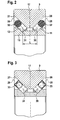
- the enlarged view in FIG. 2 indicates that at a circumferential location of the outer bearing ring 10 right and left side is provided with a respective filling opening 26, 27, whose central axis 28, 29 with the rotation axis 30, 31 of the rolling elements 11, 12 are aligned. It can be seen that in this way the tapered roller bearing 8 according to the invention can be filled in a simple manner from outside to inside with the rolling bodies 11, 12. After the filling process is completed, both filling openings 26, 27 are closed by a respective plastic ball 32, which is slightly larger in diameter than the filling opening 26, 27 is. Also, it has proved to be advantageous if the diameter of the filling opening 26, 27 is slightly larger than the diameter of the two cylindrical rolling elements 11, 12, because this simplifies the filling of the bearing with the rolling elements 11, 12. It can also be seen from the figure that the axial distance between the two rows of rolling elements 11, 12 denoted by L is not influenced by the filling plug in the form of the plastic ball 32.
- FIGS. 2 and 3 The difference between the FIGS. 2 and 3 is that the plastic ball used as filling stopper 32 in FIG. 2 through a centering 33 in FIG. 3 is replaced.
- this centering 33 consists of a non-cutting shaped sleeve 34 which is closed at one end by the bottom 35 having a central elevation 36. Between this elevation 36 and the sleeve 34, a ball ring 37 is arranged, which carries a substantially larger diameter bearing ball 38 which is secured to the outside against falling out of the sleeve 34 by a flange 39.
- a rolling friction is realized by the centering.
Description
Die Erfindung betrifft ein zweireihiges Schrägrollenlager, welches aus einem äußeren Lagerring und einem inneren Lagerring sowie aus einer Anzahl zwischen den Lagerringen in zwei Reihen nebeneinander angeordneter zylindrischer Wälzkörper besteht, die zueinander in O-Anordnung angestellt sind und auf Laufbahnen abwälzen, welche unter einem Winkel geneigt zu einer Lagerachse verlaufen, wobei jede Wälzkörperreihe mit einer außerhalb der Laufbahn liegenden Einfüllöffnung versehen ist, deren Mittelachse eine Verlängerung von Rotationsachsen der Wälzkörper ist und beide Einfüllöffnungen nach dem Einfüllen der Wälzkörper durch einen Füllstopfen verschlossen sind.The invention relates to a double-row tapered roller bearing, which consists of an outer bearing ring and an inner bearing ring and a number between the bearing rings in two rows of juxtaposed cylindrical rolling elements, which are employed to each other in O arrangement and roll on tracks, which are inclined at an angle extend to a bearing axis, wherein each row of rolling elements is provided with a lying outside the raceway filling opening whose central axis is an extension of axes of rotation of the rolling elements and both filling openings are closed after filling of the rolling elements by a Füllstopfen.
Zweireihige Schrägrollenlager kommen immer dann zur Anwendung, wenn auf gleichem Bauraum zweireihige Schrägkugellager oder auch ein Kreuzrollenlager nicht mehr die notwendigen Kräfte (Lebensdauer) oder Momente (Kippsteifigkeit) übertragen können. Eine typische Ausführungsform derartiger Lager geht aus dem SKF-Katalog 3135 T "RKS Schwenklager", Seite 96 hervor. Diese zweireihig ausgebildeten Schwenklager haben einteilige Ringe. Die Rollen aus einem Wälzlagerstahl werden durch eine gemeinsame Einfüllöffnung in einem Lagerring in das Lager eingeschoben, wobei die Einfüllöffnung nach dem Einbringen der Wälzkörper mit einem Stopfen zu verschließen ist.Double-row tapered roller bearings are always used when two-row angular contact ball bearings or cross-roller bearings can no longer transmit the necessary forces (service life) or moments (tilting rigidity) in the same space. A typical embodiment of such bearings is shown in the SKF catalog 3135 T "RKS pivot bearing", page 96. These double-row pivot bearings have one-piece rings. The roles From a rolling bearing steel are inserted through a common filling opening in a bearing ring in the camp, the filler opening is to close after the introduction of the rolling elements with a stopper.
Nachteilig dabei ist, dass die Einfüllöffnung Bestandteil der Laufbahn ist. Dies hat zur Folge, dass der die Einfüllöffnung zu verschließende Füllstopfen ebenso aufwendig zu behandeln ist wie die Laufbahn. Dieser Füllstopfen muss daher auch gehärtet und überschliffen werden. Darüber hinaus bildet ein solcher Füllstopfen eine Stoßkante für die Wälzkörper, sodass Geräusche oder Schwingungen vorprogrammiert sind. Für bestimmte Anwendungsfälle, zum Beispiel in der Medizintechnik, sind aber sehr geräusch- und stoßarme Lagerungen ein unbedingtes Erfordernis. Ein weiterer Nachteil ist darin begründet, dass der dieThe disadvantage here is that the filling opening is part of the career. This has the consequence that the filling opening to be closed filling plug is just as expensive to handle as the career. This filler plug must therefore also be hardened and ground. In addition, such a filling plug forms a contact edge for the rolling elements, so that noises or vibrations are preprogrammed. For certain applications, for example in medical technology, but very low noise and low-impact bearings are an absolute requirement. Another disadvantage is due to the fact that the
Laufbahn verschließende Füllstopfen gesichert werden muss, was wiederum eine relativ große radiale Ausdehnung des Lagerringes bewirkt. Es ist weiter von Nachteil, dass der Füllstopfen den Abstand beider Laufbahnen zueinander begrenzt, da dieser umso breiter werden muss, je weiter die Laufbahnen in axialer Richtung voneinander entfernt sind.Race closing filler plug must be secured, which in turn causes a relatively large radial expansion of the bearing ring. It is also disadvantageous that the filling plug limits the distance between the two raceways relative to one another, since the latter has to be widened the farther the raceways are in the axial direction from one another.
Ein zweireihiges Schrägrollenlager mit den Merkmalen des Oberbegriffs von Anspruch 1 ist beispielsweise aus der
Ein weiteres zweireihiges Schrägrollenlager ist aus der
Ausgehend davon liegt der Erfindung daher die Aufgabe zugrunde, ein gattungsgemäßes Schrägrollenlager so weiter zu entwickeln, dass einerseits das Laufverhalten verbessert und andererseits eine weitere Miniaturisierung des Lagers möglich ist.Proceeding from this, the object of the invention is therefore to further develop a generic tapered roller bearing in such a way that, on the one hand, the running behavior is improved and, on the other hand, further miniaturization of the bearing is possible.
Erfindungsgemäß wird diese Aufgabe nach dem kennzeichnenden Teil von Anspruch 1 in Verbindung mit dessen Oberbegriff dadurch gelöst, dass jede Wälzkörperreihe mit einer außerhalb der Laufbahn liegenden Einfüllöffnung versehen ist, deren Mittelachse eine Verlängerung von Rotationsachsen der Wälzkörper ist und beide Einfüllöffnungen nach dem Einfüllen der Wälzkörper durch einen Füllstopfen verschlossen sind.According to the invention, this object is achieved by the characterizing part of claim 1 in conjunction with the preamble thereof, that each rolling element row is provided with a lying outside the raceway filling opening whose central axis is an extension of axes of rotation of the rolling elements and both filling openings after filling of the rolling elements a filling plug are closed.
Der entscheidende Vorteil der erfindungsgemäßen Lösung liegt darin, dass die Füllstopfen nicht mehr Bestandteil der Laufbahnen sind. Dadurch verringert sich der Fertigungsaufwand wesentlich, da die verwendeten Füllstopfen keine Laufbahnqualitäten aufweisen müssen. Auch werden die Laufeigenschaften des Lagers verbessert, da die Laufbahnen nicht mehr unterbrochen sind und daher das Lager sehr stoß- und geräuscharm arbeitet. Durch das Wegfallen der Fixierung des Füllstopfens in einem der Lagerringe kann dieser auch in seiner radialen Ausdehnung verringert werden, was sich insbesondere vorteilhaft bei mangelndem Bauraum auswirkt. Es ist weiter von Vorteil, dass im Gegensatz zum bisherigen Stand der Technik eine Verbreiterung des axialen Abstandes beider Laufbahnen voneinander ohne Probleme möglich ist, da dies ohne Einfluss auf den Füllstopfen ist, da dieser, wie bereits ausgeführt, nicht mehr Bestandteil der Laufbahnen ist.The decisive advantage of the solution according to the invention is that the filling plugs are no longer part of the raceways. As a result, the production costs are significantly reduced, since the filler used must have no career qualities. Also, the running properties of the bearing are improved because the tracks are no longer interrupted and therefore the camp works very shock and quiet. By eliminating the fixation of the Füllstopfens in one of the bearing rings this can be reduced in its radial extent, which is particularly advantageous in a lack of space. It is also advantageous that, in contrast to the prior art broadening the axial distance between the two tracks from each other without problems is possible, since this has no influence on the filling plug, since this, as already stated, is no longer part of the raceways.
Gemäß einer nicht beanspruchten Bauform eines zweireihigen Schrägrollenlagers ist der Füllstopfen eine Kunststoffkugel, die mit Übermaß in die Einfüllöffnung eingepresst ist. Derartige Kunststoffkugeln sind als billiges Zukaufteil in den verschiedensten Materialzusammensetzung und Größenverhältnissen auf dem Markt erstehbar und daher besonders kostengünstig. Der Verschluss der Einfüllöffnungen durch die Stopfen sorgt dafür, dass einerseits kein Schmutz von außen nach innen in das Lager eindringen kann und dass andererseits kein Schmiermittel aus dem Lager von innen nach außen gelangen kann.According to an unclaimed design of a double-row tapered roller bearing, the filling plug is a plastic ball which is pressed with excess into the filling opening. Such plastic balls are available as a cheap purchased part in a variety of material composition and size ratios on the market and therefore particularly cost-effective. The closure of the filling holes through the plugs ensures that on the one hand no dirt can penetrate from the outside to the inside of the bearing and that on the other hand no lubricant can get out of the bearing from the inside out.
Bei dem erfindungsgemäßen Schrägrollenlager soll der Füllstopfen als ein spanlos gefertigtes Zentrierlager ausgebildet sein, welches aus einer Hülse besteht, deren Boden einen Kugelkranz aufnimmt, dessen mittig angeordneter Freiraum eine einzelne, im Durchmesser größere Lagerkugel aufnimmt. Diese Art von Einfüllstopfen ist zwar relativ aufwendig zu fertigen, erlaubt aber eine Wälzbewegung zwischen Füllstopfen und Wälzkörper im Bereich Einfüllöffnung.In the tapered roller bearing according to the invention, the filling stopper should be designed as a chipless manufactured centering, which consists of a sleeve whose bottom receives a ball race whose centrally arranged space receives a single, larger diameter bearing ball. Although this type of filler plug is relatively expensive to manufacture, but allows a rolling movement between filler and rolling elements in the filling opening.
Nach einem weiteren zusätzlichen Merkmal können die Wälzkörper entweder vollrollig oder durch ein Zwischenstück in Umfangsrichtung voneinander beabstandet angeordnet sein. Die vollrollige Anordnung der Wälzkörper ermöglicht eine besonders hohe Tragfähigkeit, während durch die eingeführten Zwischenstücke ein besonders ruhiger Lauf des Lagers realisiert ist.According to a further additional feature, the rolling elements can be arranged either full complement or spaced apart by an intermediate piece in the circumferential direction. The full complement arrangement of the rolling elements allows a particularly high load capacity, while a particularly smooth running of the bearing is realized by the imported intermediate pieces.
Auch soll nach einem weiteren Merkmal der Erfindung die Einfüllöffnung im Durchmesser geringfügig größer als der Durchmesser der Wälzkörper sein. Durch diese unterschiedlichen Größenverhältnisse wird das Befüllen des Lagers mit dem Wälzkörpern vereinfacht.Also, according to a further feature of the invention, the filling opening should be slightly larger in diameter than the diameter of the rolling elements. These different proportions simplify the filling of the bearing with the rolling elements.
Schließlich soll nach einem letzten Merkmal der Erfindung einer der Lagerringe mit einem Dichtelement versehen sein, das am zugehörigen anderen Lagerring unter Vorspannung anliegt.Finally, according to a last feature of the invention, one of the bearing rings should be provided with a sealing element which bears against the associated other bearing ring under prestress.
Weitere Merkmale der Erfindung ergeben sich aus der nachfolgenden Beschreibung und aus den Zeichnungen, in denen ein Ausführungsbeispiel der Erfindung sowie zum Vergleich eine nicht beanspruchte Ausführungsform eines Lagers in vereinfachter Form dargestellt sind.Further features of the invention will become apparent from the following description and from the drawings, in which an embodiment of the invention and for comparison an unclaimed embodiment of a bearing are shown in simplified form.
Es zeigen:
- Figur 1
- einen Längsschnitt durch ein erfindungsgemäß ausgestal- tetes Schrägrollenlager,
- Figur 2
- einen Längsschnitt durch ein nicht beanspruchtes Lager im Bereich der Einfüllöffnung,
Figur 3- einen Längsschnitt durch das erfindungsgemäße Lager im Bereich der Einfüllöffnung,
- Figur 4
- eine vergrößerte Darstellung einer Einzelheit aus
Figur 3 Figur 5- einen Längsschnitt durch ein Schrägrollenlager nach dem bisherigen Stand der Technik
- FIG. 1
- a longitudinal section through an inventively designed inclined roller bearing,
- FIG. 2
- a longitudinal section through an unclaimed bearing in the region of the filling opening,
- FIG. 3
- a longitudinal section through the bearing according to the invention in the region of the filling opening,
- FIG. 4
- an enlarged view of a detail
FIG. 3 and - FIG. 5
- a longitudinal section through a tapered roller bearing according to the prior art
Zur Erläuterung des bisherigen Standes der Technik wird zunächst auf
Wie aus
Die vergrößerte Darstellung in
Der Unterschied zwischen den
BezugszahlenlisteLIST OF REFERENCE NUMBERS
- 11
- äußerer Lagerringouter bearing ring
- 22
- innerer Lagerringinner bearing ring
- 33
- Wälzkörperrolling elements
- 44
- Wälzkörperrolling elements
- 55
- Befestigungsschraubefixing screw
- 66
- Lagerachsebearing axle
- 77
- Füllstopfenfilling plug
- 88th
- SchrägrollenlagerTapered roller bearings
- 99
- äußerer Lagerringouter bearing ring
- 1010
- innerer Lagerringinner bearing ring
- 1111
- Wälzkörperrolling elements
- 1212
- Wälzkörperrolling elements
- 1313
- dreieckförmiger Bereichtriangular area
- 1414
- AußenlaufbahnOuter race
- 1515
- AußenlaufbahnOuter race
- 1616
- Lagerachsebearing axle
- 1717
- Schmierrillelubrication groove
- 1818
- SchmiermitteldurchtrittsbohrungLubricant through bore
- 1919
- Bordshelf
- 2020
- Bordshelf
- 2121
- Bordshelf
- 2222
- Bordshelf
- 2323
- InnenlaufbahnInner raceway
- 2424
- InnenlaufbahnInner raceway
- 2525
- Befestigungsbohrungmounting hole
- 2626
- Einfüllöffnungfill opening
- 2727
- Einfüllöffnungfill opening
- 2828
- Mittelachsecentral axis
- 2929
- Mittelachsecentral axis
- 3030
- Rotationsachseaxis of rotation
- 3131
- Rotationsachseaxis of rotation
- 3232
- KunststoffkugelPlastic ball
- 3333
- Zentrierlagercentering
- 3434
- Hülseshell
- 3535
- Bodenground
- 3636
- Erhebungsurvey
- 3737
- Kugelkranzball race
- 3838
- Lagerkugelbearing ball
- 3939
- Bördelbordflange rim
- LL
- Abstanddistance
- αα
- Neigungswinkeltilt angle
Claims (4)
- Double-row angular-contact roller bearing (8) which comprises an outer bearing ring (9), an inner bearing ring (10) and a number of cylindrical rolling bodies (11, 12) which are arranged in two rows next to one another between the bearing rings (9, 10), are set against one another in an O-arrangement and roll on raceways (14, 15, 23, 24) which extend inclined at an angle with respect to a bearing axis (16), each rolling-body row (11, 12) being provided with a filling opening (26, 27) which lies outside the raceway (14, 15, 23, 24) and the centre axis (28, 29) of which is an extension of rotational axes (30, 31) of the rolling bodies (11, 12), and both filling openings (26, 27) being closed by a filling plug (32, 33) after filling with the rolling bodies (11, 12), characterized in that the filling plug is configured as a centring bearing (33) which is produced without the removal of material and comprises a sleeve (34), the bottom (35) of which receives a ball race (37), the centrally arranged clearance of which receives a single bearing ball (38) of relatively large diameter.
- Double-row angular-contact roller bearing (8) according to Claim 1, characterized in that the rolling bodies (11, 12) are arranged as a full set or spaced apart from one another in the circumferential direction by an intermediate piece.
- Double-row angular-contact roller bearing (8) according to Claim 1, characterized in that the filling opening (26, 27) has a slightly larger diameter than the diameter of the rolling bodies (11, 12).
- Double-row angular-contact roller bearing (8) according to Claim 1, characterized in that one of the bearing rings (9, 10) is provided with a sealing element which bears under prestress against the associated other bearing ring (10, 9).
Applications Claiming Priority (1)
| Application Number | Priority Date | Filing Date | Title |
|---|---|---|---|
| DE200710013944 DE102007013944A1 (en) | 2007-03-23 | 2007-03-23 | Tapered roller bearings |
Publications (2)
| Publication Number | Publication Date |
|---|---|
| EP1972802A1 EP1972802A1 (en) | 2008-09-24 |
| EP1972802B1 true EP1972802B1 (en) | 2010-10-06 |
Family
ID=39323610
Family Applications (1)
| Application Number | Title | Priority Date | Filing Date |
|---|---|---|---|
| EP20080152139 Active EP1972802B1 (en) | 2007-03-23 | 2008-02-29 | Inclined roller bearing |
Country Status (4)
| Country | Link |
|---|---|
| EP (1) | EP1972802B1 (en) |
| CN (1) | CN101270776B (en) |
| DE (2) | DE102007013944A1 (en) |
| ES (1) | ES2352821T3 (en) |
Families Citing this family (7)
| Publication number | Priority date | Publication date | Assignee | Title |
|---|---|---|---|---|
| DE102010014771A1 (en) | 2010-04-13 | 2011-10-13 | Schaeffler Technologies Gmbh & Co. Kg | Double-row tapered roller bearing for use in wind power plant, comprises outer bearing ring, inner bearing ring, and multiple rollers arranged between two bearing rings next to each other in two rows |
| DE102011005725A1 (en) | 2011-03-17 | 2012-09-20 | Schaeffler Technologies Gmbh & Co. Kg | roller bearing |
| TW201239216A (en) * | 2011-03-31 | 2012-10-01 | Hiwin Tech Corp | Cross roller bearing |
| CN102954118B (en) * | 2012-11-19 | 2016-01-06 | 杭州一佳精密轴承有限公司 | A kind of assembly method of bidirectional angular contact thrust ball bearing |
| WO2017020905A1 (en) | 2015-08-04 | 2017-02-09 | Schaeffler Technologies AG & Co. KG | Angular contact roller bearing and method and device for the assembly thereof |
| DE102016223574A1 (en) | 2016-11-28 | 2018-05-30 | Minebea Mitsumi Inc. | roller bearing |
| CN111749983B (en) * | 2019-03-28 | 2023-03-28 | 新疆金风科技股份有限公司 | Bearing and bearing system of wind generating set |
Family Cites Families (12)
| Publication number | Priority date | Publication date | Assignee | Title |
|---|---|---|---|---|
| DE649218C (en) * | 1935-06-08 | 1937-08-18 | Zeiss Carl Fa | storage |
| US2055714A (en) * | 1935-11-14 | 1936-09-29 | Timken Roller Bearing Co | Roller bearing |
| US2759243A (en) * | 1952-11-18 | 1956-08-21 | Vinco Corp | Method of making preloaded bearings |
| DE1930561A1 (en) * | 1968-06-17 | 1970-01-29 | Mollificio La Leonessa S N C D | Thrust bearing |
| DE7404405U (en) * | 1973-03-20 | 1974-05-22 | Rks Pasquier | Double row angular contact cylindrical roller bearing with one-piece races |
| FR2222897A5 (en) | 1973-03-20 | 1974-10-18 | Rks | |
| GB2126667B (en) * | 1982-09-07 | 1986-05-14 | J C Engineering International | Wire-race bearings |
| JP2511112B2 (en) * | 1988-07-12 | 1996-06-26 | 日本トムソン株式会社 | Lubricator for slewing ring bearing with lid |
| IT1227656B (en) * | 1988-12-01 | 1991-04-23 | Omet S R L L | ROLLING BEARING |
| JP2583608B2 (en) * | 1989-07-05 | 1997-02-19 | 日本トムソン株式会社 | Slewing ring bearing with rolling element insertion lid and its processing method |
| FR2749624B1 (en) * | 1996-06-07 | 1998-07-10 | Roulements Soc Nouvelle | BEARING WITH RADIAL CONDUIT FOR INTRODUCING THE ROLLING BODIES |
| DE19837579A1 (en) * | 1998-08-19 | 2000-02-24 | Schaeffler Waelzlager Ohg | Rollerbearing of concentric rings and fill-hole stopper uses conical stopper of body and washer with interposed seals plus penetrating pin to position stopper body |
-
2007
- 2007-03-23 DE DE200710013944 patent/DE102007013944A1/en not_active Withdrawn
-
2008
- 2008-02-29 DE DE200850001462 patent/DE502008001462D1/en active Active
- 2008-02-29 EP EP20080152139 patent/EP1972802B1/en active Active
- 2008-02-29 ES ES08152139T patent/ES2352821T3/en active Active
- 2008-03-21 CN CN2008100830933A patent/CN101270776B/en not_active Expired - Fee Related
Also Published As
| Publication number | Publication date |
|---|---|
| CN101270776A (en) | 2008-09-24 |
| CN101270776B (en) | 2010-06-16 |
| ES2352821T3 (en) | 2011-02-23 |
| DE102007013944A1 (en) | 2008-09-25 |
| DE502008001462D1 (en) | 2010-11-18 |
| EP1972802A1 (en) | 2008-09-24 |
Similar Documents
| Publication | Publication Date | Title |
|---|---|---|
| EP1864028B1 (en) | Radial roller bearing, in particular a single-groove grooved ball bearing | |
| EP1972802B1 (en) | Inclined roller bearing | |
| DE102015201257B3 (en) | Ball screw and associated electromechanical actuator | |
| EP2994657B1 (en) | Grease-lubricated angular contact ball bearing | |
| EP3332136B1 (en) | Method and device for producing an angular contact roller bearing | |
| EP3494318B1 (en) | Method and device for fitting an angular contact roller bearing | |
| WO2007065414A1 (en) | Radial antifriction bearing, especially single-row grooved antifriction bearing | |
| EP1837536A2 (en) | Angular contact roller bearing | |
| DE102009037422A1 (en) | Cage segment for a plastic cage of a rolling bearing and rolling bearing with such a cage segment | |
| DE102006044802A1 (en) | Combined sliding ball bearing for supporting shaft in gear construction, has balls and rollers unroll on remaining shoulder surfaces, where bearing is formed as four-point ball bearing, so that running grooves have contact points | |
| DE102006019230A1 (en) | Radial rolling bearing, in particular single row ball roller bearing | |
| DE102016211435A1 (en) | Bearing unit and spacer | |
| DE102008046237A1 (en) | Roller bearing e.g. radial roller bearing, has contact area that is in contact with rim surface at contact point, which is provided on inner and outer lines, where contact area is linear when area is seen in longitudinal direction | |
| DE102005018616A1 (en) | Angular contact ball bearing has annular grooves in inner and outer rings which act as lubricant storage system and are at least partly covered by ball bearings | |
| EP2994651B1 (en) | Bearing assembly, mounting of a bevel pinion shaft | |
| DE102006004728B4 (en) | Thin section bearings | |
| WO2008068123A1 (en) | Thrust bearing of a dual-clutch transmission | |
| DE10042648A1 (en) | Ball bearing for car transmission shafts allows rotational and longitudinal movement and has balls loose, without cage, inside outer ring, shaft forming inner ring | |
| DE102005027516A1 (en) | Bicycle pedal has two sets of conical needle bearings both directed towards the pedal mid-point | |
| WO2011018490A1 (en) | Cage segment for a plastics cage of a rolling contact bearing and rolling contact bearing with a cage segment of this type | |
| EP2048388B1 (en) | Double row angular contact ball bearing | |
| DE102008047819A1 (en) | Caster with cylindrical roller bearing | |
| DE102009049557A1 (en) | Cross roller bearing for rotary connection of components in e.g. construction machine, has roller bodies, whose portion is designed in elastic deformable manner in direction perpendicular to rotation axes of roller bodies | |
| DE102020117986A1 (en) | Thrust roller bearing and method of forming a pocket cage filled with rolling elements for a thrust roller bearing | |
| EP1995476B1 (en) | Wire roller bearing |
Legal Events
| Date | Code | Title | Description |
|---|---|---|---|
| PUAI | Public reference made under article 153(3) epc to a published international application that has entered the european phase |
Free format text: ORIGINAL CODE: 0009012 |
|
| AK | Designated contracting states |
Kind code of ref document: A1 Designated state(s): AT BE BG CH CY CZ DE DK EE ES FI FR GB GR HR HU IE IS IT LI LT LU LV MC MT NL NO PL PT RO SE SI SK TR |
|
| AX | Request for extension of the european patent |
Extension state: AL BA MK RS |
|
| RIN1 | Information on inventor provided before grant (corrected) |
Inventor name: OETJEN, JUERGEN |
|
| 17P | Request for examination filed |
Effective date: 20090324 |
|
| 17Q | First examination report despatched |
Effective date: 20090427 |
|
| AKX | Designation fees paid |
Designated state(s): CH DE ES FR GB IT LI |
|
| GRAP | Despatch of communication of intention to grant a patent |
Free format text: ORIGINAL CODE: EPIDOSNIGR1 |
|
| GRAS | Grant fee paid |
Free format text: ORIGINAL CODE: EPIDOSNIGR3 |
|
| GRAA | (expected) grant |
Free format text: ORIGINAL CODE: 0009210 |
|
| AK | Designated contracting states |
Kind code of ref document: B1 Designated state(s): CH DE ES FR GB IT LI |
|
| REG | Reference to a national code |
Ref country code: GB Ref legal event code: FG4D Free format text: NOT ENGLISH |
|
| REG | Reference to a national code |
Ref country code: CH Ref legal event code: EP |
|
| REF | Corresponds to: |
Ref document number: 502008001462 Country of ref document: DE Date of ref document: 20101118 Kind code of ref document: P |
|
| REG | Reference to a national code |
Ref country code: ES Ref legal event code: FG2A Effective date: 20110211 |
|
| PLBE | No opposition filed within time limit |
Free format text: ORIGINAL CODE: 0009261 |
|
| STAA | Information on the status of an ep patent application or granted ep patent |
Free format text: STATUS: NO OPPOSITION FILED WITHIN TIME LIMIT |
|
| 26N | No opposition filed |
Effective date: 20110707 |
|
| REG | Reference to a national code |
Ref country code: DE Ref legal event code: R097 Ref document number: 502008001462 Country of ref document: DE Effective date: 20110707 |
|
| REG | Reference to a national code |
Ref country code: CH Ref legal event code: PFA Owner name: SCHAEFFLER TECHNOLOGIES AG & CO. KG Free format text: SCHAEFFLER TECHNOLOGIES GMBH & CO. KG#INDUSTRIESTRASSE 1-3#91074 HERZOGENAURACH (DE) -TRANSFER TO- SCHAEFFLER TECHNOLOGIES AG & CO. KG#INDUSTRIESTRASSE 1-3#91074 HERZOGENAURACH (DE) |
|
| REG | Reference to a national code |
Ref country code: DE Ref legal event code: R081 Ref document number: 502008001462 Country of ref document: DE Owner name: SCHAEFFLER TECHNOLOGIES AG & CO. KG, DE Free format text: FORMER OWNER: SCHAEFFLER TECHNOLOGIES GMBH & CO. KG, 91074 HERZOGENAURACH, DE Effective date: 20120828 Ref country code: DE Ref legal event code: R081 Ref document number: 502008001462 Country of ref document: DE Owner name: SCHAEFFLER TECHNOLOGIES GMBH & CO. KG, DE Free format text: FORMER OWNER: SCHAEFFLER TECHNOLOGIES GMBH & CO. KG, 91074 HERZOGENAURACH, DE Effective date: 20120828 |
|
| REG | Reference to a national code |
Ref country code: ES Ref legal event code: PC2A Owner name: SCHAEFFLER TECHNOLOGIES AG & CO.KG Effective date: 20130617 |
|
| REG | Reference to a national code |
Ref country code: DE Ref legal event code: R081 Ref document number: 502008001462 Country of ref document: DE Owner name: SCHAEFFLER TECHNOLOGIES AG & CO. KG, DE Free format text: FORMER OWNER: SCHAEFFLER TECHNOLOGIES AG & CO. KG, 91074 HERZOGENAURACH, DE Effective date: 20140218 Ref country code: DE Ref legal event code: R081 Ref document number: 502008001462 Country of ref document: DE Owner name: SCHAEFFLER TECHNOLOGIES GMBH & CO. KG, DE Free format text: FORMER OWNER: SCHAEFFLER TECHNOLOGIES AG & CO. KG, 91074 HERZOGENAURACH, DE Effective date: 20140218 |
|
| REG | Reference to a national code |
Ref country code: CH Ref legal event code: PFUS Owner name: SCHAEFFLER TECHNOLOGIES GMBH AND CO. KG, DE Free format text: FORMER OWNER: SCHAEFFLER TECHNOLOGIES AG AND CO. KG, DE |
|
| REG | Reference to a national code |
Ref country code: CH Ref legal event code: PFA Owner name: SCHAEFFLER TECHNOLOGIES AG AND CO. KG, DE Free format text: FORMER OWNER: SCHAEFFLER TECHNOLOGIES GMBH AND CO. KG, DE |
|
| REG | Reference to a national code |
Ref country code: DE Ref legal event code: R081 Ref document number: 502008001462 Country of ref document: DE Owner name: SCHAEFFLER TECHNOLOGIES AG & CO. KG, DE Free format text: FORMER OWNER: SCHAEFFLER TECHNOLOGIES GMBH & CO. KG, 91074 HERZOGENAURACH, DE Effective date: 20150223 |
|
| REG | Reference to a national code |
Ref country code: ES Ref legal event code: PC2A Owner name: SCHAEFFLER TECHNOLOGIES AG & CO.KG Effective date: 20150512 |
|
| REG | Reference to a national code |
Ref country code: FR Ref legal event code: PLFP Year of fee payment: 9 |
|
| REG | Reference to a national code |
Ref country code: FR Ref legal event code: PLFP Year of fee payment: 10 |
|
| REG | Reference to a national code |
Ref country code: FR Ref legal event code: PLFP Year of fee payment: 11 |
|
| PGFP | Annual fee paid to national office [announced via postgrant information from national office to epo] |
Ref country code: DE Payment date: 20220420 Year of fee payment: 15 |
|
| PGFP | Annual fee paid to national office [announced via postgrant information from national office to epo] |
Ref country code: FR Payment date: 20230220 Year of fee payment: 16 Ref country code: CH Payment date: 20230307 Year of fee payment: 16 |
|
| PGFP | Annual fee paid to national office [announced via postgrant information from national office to epo] |
Ref country code: IT Payment date: 20230223 Year of fee payment: 16 Ref country code: GB Payment date: 20230220 Year of fee payment: 16 |
|
| PGFP | Annual fee paid to national office [announced via postgrant information from national office to epo] |
Ref country code: ES Payment date: 20230424 Year of fee payment: 16 |
|
| REG | Reference to a national code |
Ref country code: DE Ref legal event code: R119 Ref document number: 502008001462 Country of ref document: DE |
|
| PG25 | Lapsed in a contracting state [announced via postgrant information from national office to epo] |
Ref country code: DE Free format text: LAPSE BECAUSE OF NON-PAYMENT OF DUE FEES Effective date: 20230901 |
|
| PGFP | Annual fee paid to national office [announced via postgrant information from national office to epo] |
Ref country code: ES Payment date: 20240325 Year of fee payment: 17 |