EP1972410A1 - Spindle apparatus - Google Patents
Spindle apparatus Download PDFInfo
- Publication number
- EP1972410A1 EP1972410A1 EP08005479A EP08005479A EP1972410A1 EP 1972410 A1 EP1972410 A1 EP 1972410A1 EP 08005479 A EP08005479 A EP 08005479A EP 08005479 A EP08005479 A EP 08005479A EP 1972410 A1 EP1972410 A1 EP 1972410A1
- Authority
- EP
- European Patent Office
- Prior art keywords
- attaching portion
- spindle
- tool attaching
- radial
- tool
- Prior art date
- Legal status (The legal status is an assumption and is not a legal conclusion. Google has not performed a legal analysis and makes no representation as to the accuracy of the status listed.)
- Granted
Links
- 238000006073 displacement reaction Methods 0.000 claims abstract description 39
- 238000003754 machining Methods 0.000 claims description 5
- 238000001514 detection method Methods 0.000 description 6
- 238000010276 construction Methods 0.000 description 4
- 230000003247 decreasing effect Effects 0.000 description 3
- 238000010586 diagram Methods 0.000 description 2
- 238000005096 rolling process Methods 0.000 description 2
- 244000145845 chattering Species 0.000 description 1
- 239000000470 constituent Substances 0.000 description 1
- 230000000694 effects Effects 0.000 description 1
- 238000000034 method Methods 0.000 description 1
- 230000002093 peripheral effect Effects 0.000 description 1
Images


Classifications
-
- B—PERFORMING OPERATIONS; TRANSPORTING
- B23—MACHINE TOOLS; METAL-WORKING NOT OTHERWISE PROVIDED FOR
- B23Q—DETAILS, COMPONENTS, OR ACCESSORIES FOR MACHINE TOOLS, e.g. ARRANGEMENTS FOR COPYING OR CONTROLLING; MACHINE TOOLS IN GENERAL CHARACTERISED BY THE CONSTRUCTION OF PARTICULAR DETAILS OR COMPONENTS; COMBINATIONS OR ASSOCIATIONS OF METAL-WORKING MACHINES, NOT DIRECTED TO A PARTICULAR RESULT
- B23Q1/00—Members which are comprised in the general build-up of a form of machine, particularly relatively large fixed members
- B23Q1/70—Stationary or movable members for carrying working-spindles for attachment of tools or work
-
- B—PERFORMING OPERATIONS; TRANSPORTING
- B23—MACHINE TOOLS; METAL-WORKING NOT OTHERWISE PROVIDED FOR
- B23Q—DETAILS, COMPONENTS, OR ACCESSORIES FOR MACHINE TOOLS, e.g. ARRANGEMENTS FOR COPYING OR CONTROLLING; MACHINE TOOLS IN GENERAL CHARACTERISED BY THE CONSTRUCTION OF PARTICULAR DETAILS OR COMPONENTS; COMBINATIONS OR ASSOCIATIONS OF METAL-WORKING MACHINES, NOT DIRECTED TO A PARTICULAR RESULT
- B23Q17/00—Arrangements for observing, indicating or measuring on machine tools
- B23Q17/09—Arrangements for observing, indicating or measuring on machine tools for indicating or measuring cutting pressure or for determining cutting-tool condition, e.g. cutting ability, load on tool
- B23Q17/0952—Arrangements for observing, indicating or measuring on machine tools for indicating or measuring cutting pressure or for determining cutting-tool condition, e.g. cutting ability, load on tool during machining
- B23Q17/0971—Arrangements for observing, indicating or measuring on machine tools for indicating or measuring cutting pressure or for determining cutting-tool condition, e.g. cutting ability, load on tool during machining by measuring mechanical vibrations of parts of the machine
- B23Q17/0976—Detection or control of chatter
-
- B—PERFORMING OPERATIONS; TRANSPORTING
- B24—GRINDING; POLISHING
- B24B—MACHINES, DEVICES, OR PROCESSES FOR GRINDING OR POLISHING; DRESSING OR CONDITIONING OF ABRADING SURFACES; FEEDING OF GRINDING, POLISHING, OR LAPPING AGENTS
- B24B41/00—Component parts such as frames, beds, carriages, headstocks
- B24B41/007—Weight compensation; Temperature compensation; Vibration damping
-
- F—MECHANICAL ENGINEERING; LIGHTING; HEATING; WEAPONS; BLASTING
- F16—ENGINEERING ELEMENTS AND UNITS; GENERAL MEASURES FOR PRODUCING AND MAINTAINING EFFECTIVE FUNCTIONING OF MACHINES OR INSTALLATIONS; THERMAL INSULATION IN GENERAL
- F16C—SHAFTS; FLEXIBLE SHAFTS; ELEMENTS OR CRANKSHAFT MECHANISMS; ROTARY BODIES OTHER THAN GEARING ELEMENTS; BEARINGS
- F16C32/00—Bearings not otherwise provided for
- F16C32/04—Bearings not otherwise provided for using magnetic or electric supporting means
- F16C32/0402—Bearings not otherwise provided for using magnetic or electric supporting means combined with other supporting means, e.g. hybrid bearings with both magnetic and fluid supporting means
-
- F—MECHANICAL ENGINEERING; LIGHTING; HEATING; WEAPONS; BLASTING
- F16—ENGINEERING ELEMENTS AND UNITS; GENERAL MEASURES FOR PRODUCING AND MAINTAINING EFFECTIVE FUNCTIONING OF MACHINES OR INSTALLATIONS; THERMAL INSULATION IN GENERAL
- F16C—SHAFTS; FLEXIBLE SHAFTS; ELEMENTS OR CRANKSHAFT MECHANISMS; ROTARY BODIES OTHER THAN GEARING ELEMENTS; BEARINGS
- F16C32/00—Bearings not otherwise provided for
- F16C32/04—Bearings not otherwise provided for using magnetic or electric supporting means
- F16C32/0406—Magnetic bearings
- F16C32/044—Active magnetic bearings
- F16C32/0474—Active magnetic bearings for rotary movement
- F16C32/048—Active magnetic bearings for rotary movement with active support of two degrees of freedom, e.g. radial magnetic bearings
-
- H—ELECTRICITY
- H02—GENERATION; CONVERSION OR DISTRIBUTION OF ELECTRIC POWER
- H02K—DYNAMO-ELECTRIC MACHINES
- H02K7/00—Arrangements for handling mechanical energy structurally associated with dynamo-electric machines, e.g. structural association with mechanical driving motors or auxiliary dynamo-electric machines
- H02K7/08—Structural association with bearings
- H02K7/09—Structural association with bearings with magnetic bearings
-
- F—MECHANICAL ENGINEERING; LIGHTING; HEATING; WEAPONS; BLASTING
- F16—ENGINEERING ELEMENTS AND UNITS; GENERAL MEASURES FOR PRODUCING AND MAINTAINING EFFECTIVE FUNCTIONING OF MACHINES OR INSTALLATIONS; THERMAL INSULATION IN GENERAL
- F16C—SHAFTS; FLEXIBLE SHAFTS; ELEMENTS OR CRANKSHAFT MECHANISMS; ROTARY BODIES OTHER THAN GEARING ELEMENTS; BEARINGS
- F16C2322/00—Apparatus used in shaping articles
- F16C2322/39—General buildup of machine tools, e.g. spindles, slides, actuators
Definitions
- This invention relates to a spindle apparatus for a machine tool, and more particularly to a machine tool spindle apparatus including a spindle which is rotated with a tool attached to a distal end thereof.
- a spindle apparatus for a machine tool comprising:
- the tool attaching portion of the spindle is supported in the predetermined position by the vibration-suppressing radial magnetic bearing provided around the tool attaching portion, and therefore the generation of resonance of the spindle is suppressed even without decreasing the number of revolutions of the spindle.
- the radial magnetic bearing comprises one pair of electromagnets opposed to each other in one radial direction with the tool attaching portion interposed therebetween, and another pair of electromagnets opposed to each other in another radial direction perpendicular to the one radial direction.
- the radial magnetic bearing may comprise three electromagnets arranged at equal intervals (that is, spaced 120 degrees from one another) in a circumferential direction around the tool attaching portion.
- one pair are arranged in the one radial direction, while another pair are arranged in the other radial direction.
- the machine tool spindle apparatus of the invention further comprises a resonance frequency detector for detecting a resonance frequency of the tool attaching portion on the basis of the outputs of the radial displacement sensors, and a phase lead controller for effecting a phase lead control for the detected resonance frequency.
- the detection of the resonance frequency is effected, for example, by effecting the frequency analysis of the outputs of the displacement sensors by the use of FFT (fast Fourier transform).
- FFT fast Fourier transform
- the phase lead controller is, for example, a digital phase lead filter formed by software.
- the generation of resonance of the spindle can be suppressed without decreasing the number of revolutions of the spindle as described above.
- Fig. 1 is a longitudinal cross-sectional view showing one example of a mechanical construction of a main portion of a spindle apparatus.
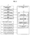
- Fig. 2 is an enlarged transverse cross-sectional view taken along the line II-II of Fig. 1 , showing a vibration suppressing device of the spindle apparatus of Fig. 1 on an enlarged scale.
- Fig. 3 is a block diagram showing one example of an electrical construction of the vibration suppressing device.
- the spindle apparatus is of the vertical type, in which a spindle 2 having a vertical axis is rotated within a vertical cylindrical housing 1.
- a Z-axis direction means an axial direction (upward-downward direction) of the spindle 2
- an X-axis direction and a Y-axis direction which are perpendicular to each other and are also perpendicular to the Z-axis direction mean two radial directions (horizontal direction), respectively.
- the bearing devices 3 and 4 comprises rolling bearings.
- the upper bearing device 3 comprises a deep groove ball bearing
- the lower bearing device 4 comprises a combination of two angular contact ball bearings.
- the two bearing devices 3 and 4 form a support-purpose bearing unit, and support the rotation of the spindle 2 in the axial direction and the radial direction.
- An internal electric motor 5 forming a driver for driving or rotating the spindle 2 is provided between the upper and lower bearing devices 3 and 4.
- the motor 5 comprises a stator 5a mounted on the housing 1, and a rotor 5b mounted on the spindle 2.
- a tool 6 is attached to this tool attaching portion 2a from the lower side.
- an end mill is attached to the tool attaching portion 2a.
- the tool 6 attached to the tool attaching portion 2a can be exchanged with other tools.
- a vertical cylindrical support member 7 is fixed to a lower end face of the housing 1.
- the support member 7 is disposed coaxially with the spindle 2, and surrounds the tool attaching portion 2a.
- a programmable radial magnetic bearing 9 for vibration suppressing purposes and a radial displacement sensor unit 10 are mounted on an inner peripheral surface of the support member 7 in surrounding relation to the tool attaching portion 2a, the magnetic bearing 9 and the sensor unit 10 forming the vibration suppressing device 8.
- the radial magnetic bearing 9 comprises a pair of electromagnets (radial electromagnets) 12a and 12b opposed to each other in the X-axis direction with a target 11 (mounted on an outer periphery of the tool attaching portion 2a) interposed therebetween, and another pair of electromagnets (radial electromagnets) 12c and 12d opposed to each other in the Y-axis direction with the target 11 interposed therebetween.
- electromagnets will hereinafter be referred to, using reference numeral 12.
- the radial displacement sensor unit 10 comprises a pair of radial displacement sensors 14a and 14b respectively disposed immediately beneath the pair of electromagnets 12a and 12b and opposed to each other in the X-axis direction with the tool attaching portion 2a interposed therebetween, and another pair of radial displacement sensors 14c and 14d respectively disposed immediately beneath the pair of electromagnets 12c and 12d and opposed to each other in the Y-axis direction with the tool attaching portion 2a interposed therebetween.
- These displacement sensors will hereinafter be referred to, using reference numeral 14.
- the electromagnets 12 and the displacement sensors 14 are electrically connected to an electromagnet control unit 15 forming an electromagnet controller.
- the electromagnet control unit 15 includes a DSP (digital signal processor) 16 serving as digital processing means capable of software programming.
- the DSP includes a displacement detection portion 17, an exciting current control portion 18, a resonance frequency detection portion 19 serving as a resonance frequency detector, and a phase lead control portion 20 serving as a phase lead controller.
- the displacement detection portion 17 detects a displacement of the tool attaching portion 2a in the X-axis direction on the basis of outputs of the pair of displacement sensors 14a and 14b, and also detects a displacement of the tool attaching portion 2a in the Y-axis direction on the basis of outputs of the other pair of displacement sensors 14c and 14d.
- the exciting current control portion 18 controls exciting currents to be supplied to the respective electromagnets 12 so that each displacement becomes a predetermined value (usually, 0).
- the exciting current is the sum of a predetermined steady-state current and a control current varying with the displacement.
- the exciting current control portion 18 calculates the control current for each electromagnet 12 on the basis of the displacement, for example, by PID control, and supplies the exciting current (which is the sum of this control current and the steady-state current) to the corresponding electromagnet 12.
- the tool attaching portion 2a is supported in a predetermined position (where each displacement is usually 0) by the radial magnetic bearing 9, and the generation of resonance of the spindle 2 is suppressed.
- the resonance frequency detection portion 19 detects the resonance frequency of the spindle 2, for example, by effecting the frequency analysis of the outputs of the displacement sensors 14 by the use of FFT.
- the phase lead control portion 20 effects a phase lead control for the detected resonance frequency of the spindle 2.
- the phase lead control portion 20 is, for example, a digital phase lead filter formed by software.
- the exciting current control portion 18 also checks whether or not a peak value of the displacement of the tool attaching portion 2a detected by the displacement detection portion 17 exceeds a predetermined threshold value, and if the peak value exceeds the threshold value, the exciting current control portion 18 increases a control gain to a level higher than an ordinary value, and increases a stiffness value of the magnetic bearing 9 to a level higher than an ordinary value. Then, if the peak value of the displacement exceeds the threshold value even when the stiffness value of the magnetic bearing 9 is increased to a certain degree, a warning is issued judging that the vibration is excessive, and preferably the machining operation is stopped.
- the constituent portions of the spindle apparatus are not limited to the above embodiment, and can be suitably modified or changed.
- the support-purpose bearing unit is of the contact type comprising the pair of rolling bearing devices of the contact type
- the support-purpose bearing unit may be of the contact type comprising other type of bearings, or may be of the non-contact type comprising, for example, a pair of axial magnetic bearings and two pairs of radial magnetic bearings, or may be of the non-contact type comprising other type of bearings, or may be of the type formed by a combination of the contact type and the non-contact type.
Landscapes
- Engineering & Computer Science (AREA)
- Mechanical Engineering (AREA)
- General Engineering & Computer Science (AREA)
- Power Engineering (AREA)
- Magnetic Bearings And Hydrostatic Bearings (AREA)
- Turning (AREA)
- Automatic Control Of Machine Tools (AREA)
- Auxiliary Devices For Machine Tools (AREA)
Abstract
Description
- This invention relates to a spindle apparatus for a machine tool, and more particularly to a machine tool spindle apparatus including a spindle which is rotated with a tool attached to a distal end thereof.
- In a machine tool spindle apparatus of the type described, when the product of the number of blades of a tool and a rotational frequency of a spindle or an integral multiple of this product is in agreement with a natural vibration of the spindle or in the vicinity of this natural vibration, resonance (chattering vibration) occurs, so that a machined surface is often rough.
- In order to prevent the generation of such resonance, there has been proposed a method in which the machining is effected with a reduced number of revolutions of the spindle so that the product of the number of the blades of the tool and the rotational frequency of the spindle or an integral multiple of this product will not brought into agreement with the natural vibration of the spindle (see, for example,
JP-A-2002-039177 - However, when the machining is carried out with the reduced number of revolutions of the spindle as described above, there is encountered a problem that the time required for the machining operation increases.
- It is an object of this invention to solve the above problem, and more specifically to provide a spindle apparatus for a machine tool in which the generation of resonance of a spindle can be suppressed without decreasing the number of revolutions of the spindle.
- According to the present invention, there is provided a spindle apparatus for a machine tool comprising:
- a housing;
- a spindle that is rotatably supported by the housing through a support-purpose bearing unit and is formed with a tool attaching portion at a distal end thereof;
- a driver that rotates the spindle;
- a tool attached to the tool attaching portion;
- a radial magnetic bearing that includes a plurality of electromagnets disposed around the tool attaching portion for suppressing vibration of the spindle;
- a plurality of radial displacement sensors provided around the tool attaching portion for detecting a displacement of the tool attaching portion in a radial direction; and
- an electromagnet controller that controls the electromagnets of the radial magnetic bearing on the basis of outputs of the radial displacement sensors so as to support the tool attaching portion in a predetermined position.
- The tool attaching portion of the spindle is supported in the predetermined position by the vibration-suppressing radial magnetic bearing provided around the tool attaching portion, and therefore the generation of resonance of the spindle is suppressed even without decreasing the number of revolutions of the spindle.
- For example, the radial magnetic bearing comprises one pair of electromagnets opposed to each other in one radial direction with the tool attaching portion interposed therebetween, and another pair of electromagnets opposed to each other in another radial direction perpendicular to the one radial direction. However, the radial magnetic bearing may comprise three electromagnets arranged at equal intervals (that is, spaced 120 degrees from one another) in a circumferential direction around the tool attaching portion.
- With respect to the radial displacement sensors, for example, one pair are arranged in the one radial direction, while another pair are arranged in the other radial direction.
- Preferably, the machine tool spindle apparatus of the invention further comprises a resonance frequency detector for detecting a resonance frequency of the tool attaching portion on the basis of the outputs of the radial displacement sensors, and a phase lead controller for effecting a phase lead control for the detected resonance frequency.
- With this construction, the generation of resonance of the spindle can be more effectively suppressed.
- The detection of the resonance frequency is effected, for example, by effecting the frequency analysis of the outputs of the displacement sensors by the use of FFT (fast Fourier transform).
- The phase lead controller is, for example, a digital phase lead filter formed by software.
- In the machine tool spindle apparatus of the present invention, the generation of resonance of the spindle can be suppressed without decreasing the number of revolutions of the spindle as described above.
- [0035]
-
-
Fig. 1 is a longitudinal cross-sectional view showing one preferred embodiment of a machine tool spindle apparatus of the present invention. -
Fig. 2 is an enlarged transverse cross-sectional view taken along the line II-II ofFig. 1 . -
Fig. 3 is a block diagram showing one example of an electrical construction of a vibration suppressing device of the machine tool spindle apparatus. - A preferred embodiment of the present invention will now be described with reference to the drawings.
-
Fig. 1 is a longitudinal cross-sectional view showing one example of a mechanical construction of a main portion of a spindle apparatus.Fig. 2 is an enlarged transverse cross-sectional view taken along the line II-II ofFig. 1 , showing a vibration suppressing device of the spindle apparatus ofFig. 1 on an enlarged scale.Fig. 3 is a block diagram showing one example of an electrical construction of the vibration suppressing device. - The spindle apparatus is of the vertical type, in which a
spindle 2 having a vertical axis is rotated within a verticalcylindrical housing 1. In the following description, a Z-axis direction means an axial direction (upward-downward direction) of thespindle 2, an X-axis direction and a Y-axis direction which are perpendicular to each other and are also perpendicular to the Z-axis direction mean two radial directions (horizontal direction), respectively. - Two portions of the
spindle 2 which are disposed adjacent respectively to upper and lower ends thereof are rotatably supported on thehousing 1 by respective bearingdevices bearing devices device 3 comprises a deep groove ball bearing, and the lower bearingdevice 4 comprises a combination of two angular contact ball bearings. The two bearingdevices spindle 2 in the axial direction and the radial direction. - An internal
electric motor 5 forming a driver for driving or rotating thespindle 2 is provided between the upper and lower bearingdevices motor 5 comprises astator 5a mounted on thehousing 1, and arotor 5b mounted on thespindle 2. - That portion of the
spindle 2 disposed downwardly of the lower bearingdevice 4 projects downwardly from thehousing 1, and serves as atool attaching portion 2a. Atool 6 is attached to thistool attaching portion 2a from the lower side. In the illustrated example, an end mill is attached to thetool attaching portion 2a. Thetool 6 attached to thetool attaching portion 2a can be exchanged with other tools. - A vertical
cylindrical support member 7 is fixed to a lower end face of thehousing 1. Thesupport member 7 is disposed coaxially with thespindle 2, and surrounds thetool attaching portion 2a. A programmable radial magnetic bearing 9 for vibration suppressing purposes and a radialdisplacement sensor unit 10 are mounted on an inner peripheral surface of thesupport member 7 in surrounding relation to thetool attaching portion 2a, the magnetic bearing 9 and thesensor unit 10 forming thevibration suppressing device 8. - The radial
magnetic bearing 9 comprises a pair of electromagnets (radial electromagnets) 12a and 12b opposed to each other in the X-axis direction with a target 11 (mounted on an outer periphery of thetool attaching portion 2a) interposed therebetween, and another pair of electromagnets (radial electromagnets) 12c and 12d opposed to each other in the Y-axis direction with thetarget 11 interposed therebetween. These electromagnets will hereinafter be referred to, using reference numeral 12. - The radial
displacement sensor unit 10 comprises a pair ofradial displacement sensors electromagnets tool attaching portion 2a interposed therebetween, and another pair ofradial displacement sensors electromagnets tool attaching portion 2a interposed therebetween. These displacement sensors will hereinafter be referred to, using reference numeral 14. - The electromagnets 12 and the displacement sensors 14 are electrically connected to an
electromagnet control unit 15 forming an electromagnet controller. - The
electromagnet control unit 15 includes a DSP (digital signal processor) 16 serving as digital processing means capable of software programming. Functionally, the DSP includes adisplacement detection portion 17, an excitingcurrent control portion 18, a resonancefrequency detection portion 19 serving as a resonance frequency detector, and a phaselead control portion 20 serving as a phase lead controller. - The
displacement detection portion 17 detects a displacement of thetool attaching portion 2a in the X-axis direction on the basis of outputs of the pair ofdisplacement sensors tool attaching portion 2a in the Y-axis direction on the basis of outputs of the other pair ofdisplacement sensors - On the basis of displacements of the
tool attaching portion 2a in the X-axis and Y-axis directions, the excitingcurrent control portion 18 controls exciting currents to be supplied to the respective electromagnets 12 so that each displacement becomes a predetermined value (usually, 0). The exciting current is the sum of a predetermined steady-state current and a control current varying with the displacement. The excitingcurrent control portion 18 calculates the control current for each electromagnet 12 on the basis of the displacement, for example, by PID control, and supplies the exciting current (which is the sum of this control current and the steady-state current) to the corresponding electromagnet 12. - Thus, the
tool attaching portion 2a is supported in a predetermined position (where each displacement is usually 0) by the radial magnetic bearing 9, and the generation of resonance of thespindle 2 is suppressed. - The resonance
frequency detection portion 19 detects the resonance frequency of thespindle 2, for example, by effecting the frequency analysis of the outputs of the displacement sensors 14 by the use of FFT. - The phase
lead control portion 20 effects a phase lead control for the detected resonance frequency of thespindle 2. The phaselead control portion 20 is, for example, a digital phase lead filter formed by software. - By effecting such phase lead control, the generation of resonance of the
spindle 2 can be more effectively suppressed. - The exciting
current control portion 18 also checks whether or not a peak value of the displacement of thetool attaching portion 2a detected by thedisplacement detection portion 17 exceeds a predetermined threshold value, and if the peak value exceeds the threshold value, the excitingcurrent control portion 18 increases a control gain to a level higher than an ordinary value, and increases a stiffness value of themagnetic bearing 9 to a level higher than an ordinary value. Then, if the peak value of the displacement exceeds the threshold value even when the stiffness value of themagnetic bearing 9 is increased to a certain degree, a warning is issued judging that the vibration is excessive, and preferably the machining operation is stopped. - The constituent portions of the spindle apparatus are not limited to the above embodiment, and can be suitably modified or changed.
- In the above embodiment, although the support-purpose bearing unit is of the contact type comprising the pair of rolling bearing devices of the contact type, the support-purpose bearing unit may be of the contact type comprising other type of bearings, or may be of the non-contact type comprising, for example, a pair of axial magnetic bearings and two pairs of radial magnetic bearings, or may be of the non-contact type comprising other type of bearings, or may be of the type formed by a combination of the contact type and the non-contact type.
Claims (7)
- A spindle apparatus for a machine tool comprising:a housing;a spindle that is rotatably supported by the housing through a support-purpose bearing unit and is formed with a tool attaching portion at a distal end thereof;a driver that rotates the spindle;a tool attached to the tool attaching portion;a radial magnetic bearing that includes a plurality of electromagnets disposed around the tool attaching portion for suppressing vibration of the spindle;a plurality of radial displacement sensors provided around the tool attaching portion for detecting a displacement of the tool attaching portion in a radial direction; andan electromagnet controller that controls the electromagnets of the radial magnetic bearing on the basis of outputs of the radial displacement sensors so as to support the tool attaching portion in a predetermined position.
- The spindle apparatus according to claim 1, wherein the electromagnet controller includes a resonance frequency detector for detecting a resonance frequency of the tool attaching portion on the basis of the outputs of the radial displacement sensors; and a phase lead controller for effecting a phase lead control for the detected resonance frequency.
- The spindle apparatus according to claim 1, wherein the support-purpose bearing unit includes a contact type bearing device.
- The spindle apparatus according to claim 1, wherein a pair of the plurality of radial displacement sensors are opposed to each other in one radial direction with the tool attaching portion interposed therebetween, and another pair of the plurality of radial displacement sensors are opposed to each other in another radial direction perpendicular to the one radial direction.
- The spindle apparatus according to claim 2, wherein the resonance frequency of the tool attaching portion is detected by effecting a frequency analysis of the outputs of the radial displacement sensors by use of fast Fourier transform.
- The spindle apparatus according to claim 1, wherein the electromagnet controller includes a digital signal processor.
- The spindle apparatus according to claim 6, wherein
the digital signal processor includes an exciting current control portion for detecting whether or not the displacement of the tool attaching portion exceeds a predetermined threshold value and,
the exciting current control portion issues a warning and stops machining operation of the spindle apparatus if the displacement exceeds the threshold value.
Applications Claiming Priority (1)
| Application Number | Priority Date | Filing Date | Title |
|---|---|---|---|
| JP2007075836A JP2008229806A (en) | 2007-03-23 | 2007-03-23 | Magnetic bearing device |
Publications (2)
| Publication Number | Publication Date |
|---|---|
| EP1972410A1 true EP1972410A1 (en) | 2008-09-24 |
| EP1972410B1 EP1972410B1 (en) | 2010-02-10 |
Family
ID=39512579
Family Applications (1)
| Application Number | Title | Priority Date | Filing Date |
|---|---|---|---|
| EP08005479A Ceased EP1972410B1 (en) | 2007-03-23 | 2008-03-25 | Spindle apparatus |
Country Status (3)
| Country | Link |
|---|---|
| US (1) | US7812493B2 (en) |
| EP (1) | EP1972410B1 (en) |
| JP (1) | JP2008229806A (en) |
Cited By (5)
| Publication number | Priority date | Publication date | Assignee | Title |
|---|---|---|---|---|
| WO2010049328A3 (en) * | 2008-10-30 | 2011-01-20 | Schaeffler Technologies Gmbh & Co. Kg | Bearing arrangement of a vertically standing drive spindle |
| CN103506892A (en) * | 2013-10-29 | 2014-01-15 | 东华大学 | Rotary type cutting force dynamic monitoring device |
| EP2899416A1 (en) * | 2014-01-22 | 2015-07-29 | Siemens Aktiengesellschaft | Electric machine with a magnet assembly |
| WO2021006931A1 (en) * | 2019-07-11 | 2021-01-14 | Lord Corporation | Rotatable shaft bearing with electromagnetically controlled support impedance |
| CN113894626A (en) * | 2021-11-10 | 2022-01-07 | 深圳市鑫国钰精密工具有限公司 | Numerical control grinding machine tool machining support device |
Families Citing this family (16)
| Publication number | Priority date | Publication date | Assignee | Title |
|---|---|---|---|---|
| JP2008229806A (en) * | 2007-03-23 | 2008-10-02 | Jtekt Corp | Magnetic bearing device |
| US20090028656A1 (en) * | 2007-07-26 | 2009-01-29 | Sawing Systems Inc. | Force monitoring and control of router |
| ITTO20110709A1 (en) * | 2011-08-01 | 2013-02-02 | Sicmat Spa | HONATRICE POWER MACHINE / GRINDING MACHINE FOR FINISHING CYLINDRICAL GEARS WITH EXTERNAL DENTAL TOOLS |
| JP5966651B2 (en) | 2012-06-19 | 2016-08-10 | 株式会社ジェイテクト | Spindle device |
| JP6265718B2 (en) * | 2013-02-25 | 2018-01-24 | 三菱重工工作機械株式会社 | Vibration control device |
| US10613629B2 (en) | 2015-03-27 | 2020-04-07 | Chad Laurendeau | System and method for force feedback interface devices |
| US10220479B2 (en) * | 2016-04-25 | 2019-03-05 | Toyota Jidosha Kabushiki Kaisha | Machining apparatus |
| JP6730912B2 (en) * | 2016-10-26 | 2020-07-29 | 三菱重工工作機械株式会社 | Spindle unit and machine tool |
| JP2019209399A (en) * | 2018-05-31 | 2019-12-12 | 国立大学法人 鹿児島大学 | Main spindle system of machine tool |
| JP7231148B2 (en) * | 2018-06-01 | 2023-03-01 | 国立大学法人 鹿児島大学 | Spindle device |
| JP6725594B2 (en) * | 2018-06-28 | 2020-07-22 | ファナック株式会社 | Spindle device |
| JP2020059102A (en) * | 2018-10-12 | 2020-04-16 | コマツNtc株式会社 | Main spindle device |
| KR102145697B1 (en) * | 2019-02-08 | 2020-08-19 | 숭실대학교산학협력단 | Vibration Damping System and Machining Force Evaluation method for machine tools using Thereof |
| US12053849B2 (en) | 2019-02-08 | 2024-08-06 | Foundation Of Soongsil University-Industry Cooperation | Vibration damping system and method for estimating cutting force of machine tool using same |
| JP2021058968A (en) * | 2019-10-07 | 2021-04-15 | 国立大学法人 鹿児島大学 | Machine tool spindle system |
| CN120921162B (en) * | 2025-10-11 | 2026-02-13 | 南通鸿翰智能装备有限公司 | Vibration suppression optimization method and system for high-rigidity gantry machine tool spindle |
Citations (5)
| Publication number | Priority date | Publication date | Assignee | Title |
|---|---|---|---|---|
| US4180946A (en) * | 1975-10-02 | 1980-01-01 | Maurice Brunet | Tool holding spindle assembly particularly for a grinding machine |
| WO1988003458A1 (en) * | 1986-11-13 | 1988-05-19 | Societe Europeenne De Propulsion | Workpiece-holder spindle with magnetic bearings and devices for implementing such spindle for very high precision machine-tool |
| EP0674112A1 (en) * | 1994-03-17 | 1995-09-27 | Seiko Seiki Kabushiki Kaisha | Spindle apparatus |
| JP2002039177A (en) | 2000-07-24 | 2002-02-06 | Ntn Corp | Non-contact bearing spindle device |
| DE102005001494A1 (en) * | 2005-01-12 | 2006-07-20 | Siemens Ag | Control method for a magnetic bearing and device corresponding thereto |
Family Cites Families (7)
| Publication number | Priority date | Publication date | Assignee | Title |
|---|---|---|---|---|
| JP3425475B2 (en) * | 1994-07-12 | 2003-07-14 | セイコーインスツルメンツ株式会社 | Magnetic bearing device |
| JPH1199433A (en) | 1997-09-26 | 1999-04-13 | Yaskawa Electric Corp | Spindle drive mechanism |
| JP4228325B2 (en) * | 1998-11-12 | 2009-02-25 | 株式会社安川電機 | Magnetic bearing control device for machine tool and control method thereof |
| JP2000167739A (en) | 1998-12-07 | 2000-06-20 | Mori Seiki Co Ltd | Machine Tools |
| JP2001041240A (en) | 1999-07-29 | 2001-02-13 | Koyo Seiko Co Ltd | Control device for magnetic bearing |
| JP4287213B2 (en) * | 2002-09-03 | 2009-07-01 | エドワーズ株式会社 | Magnetic bearing device having vibration suppressing function, magnetic bearing device having vibration estimating function, and pump device equipped with the magnetic bearing device |
| JP2008229806A (en) * | 2007-03-23 | 2008-10-02 | Jtekt Corp | Magnetic bearing device |
-
2007
- 2007-03-23 JP JP2007075836A patent/JP2008229806A/en active Pending
-
2008
- 2008-03-21 US US12/076,741 patent/US7812493B2/en not_active Expired - Fee Related
- 2008-03-25 EP EP08005479A patent/EP1972410B1/en not_active Ceased
Patent Citations (5)
| Publication number | Priority date | Publication date | Assignee | Title |
|---|---|---|---|---|
| US4180946A (en) * | 1975-10-02 | 1980-01-01 | Maurice Brunet | Tool holding spindle assembly particularly for a grinding machine |
| WO1988003458A1 (en) * | 1986-11-13 | 1988-05-19 | Societe Europeenne De Propulsion | Workpiece-holder spindle with magnetic bearings and devices for implementing such spindle for very high precision machine-tool |
| EP0674112A1 (en) * | 1994-03-17 | 1995-09-27 | Seiko Seiki Kabushiki Kaisha | Spindle apparatus |
| JP2002039177A (en) | 2000-07-24 | 2002-02-06 | Ntn Corp | Non-contact bearing spindle device |
| DE102005001494A1 (en) * | 2005-01-12 | 2006-07-20 | Siemens Ag | Control method for a magnetic bearing and device corresponding thereto |
Cited By (7)
| Publication number | Priority date | Publication date | Assignee | Title |
|---|---|---|---|---|
| WO2010049328A3 (en) * | 2008-10-30 | 2011-01-20 | Schaeffler Technologies Gmbh & Co. Kg | Bearing arrangement of a vertically standing drive spindle |
| CN103506892A (en) * | 2013-10-29 | 2014-01-15 | 东华大学 | Rotary type cutting force dynamic monitoring device |
| CN103506892B (en) * | 2013-10-29 | 2015-12-30 | 东华大学 | A kind of rotary cutting force dynamic monitor |
| EP2899416A1 (en) * | 2014-01-22 | 2015-07-29 | Siemens Aktiengesellschaft | Electric machine with a magnet assembly |
| WO2021006931A1 (en) * | 2019-07-11 | 2021-01-14 | Lord Corporation | Rotatable shaft bearing with electromagnetically controlled support impedance |
| US11846318B2 (en) | 2019-07-11 | 2023-12-19 | Lord Corporation | Rotatable shaft bearing with electromagnetically controlled support impedance |
| CN113894626A (en) * | 2021-11-10 | 2022-01-07 | 深圳市鑫国钰精密工具有限公司 | Numerical control grinding machine tool machining support device |
Also Published As
| Publication number | Publication date |
|---|---|
| US7812493B2 (en) | 2010-10-12 |
| US20080231129A1 (en) | 2008-09-25 |
| EP1972410B1 (en) | 2010-02-10 |
| JP2008229806A (en) | 2008-10-02 |
Similar Documents
| Publication | Publication Date | Title |
|---|---|---|
| EP1972410B1 (en) | Spindle apparatus | |
| US6653756B2 (en) | Magnetic bearing device | |
| CN107013596B (en) | Rolling bearing device and method for detecting abnormality of rolling bearing | |
| EP1970164B1 (en) | Method of controlling a grinding apparatus | |
| US5562528A (en) | Machine tool | |
| JP6407905B2 (en) | Main shaft bearing protection device and machine tool equipped with the same | |
| US10320261B2 (en) | Rotor alignment for reducing vibrations and noise | |
| US10439468B2 (en) | Motor including bearing seating unit | |
| JP5560892B2 (en) | Machine tool spindle equipment | |
| JP2006022914A (en) | Magnetic bearing device | |
| EP3146220B1 (en) | Gas bearing spindles | |
| EP1239353A3 (en) | Rotation stabilizing device in a microgravitational rotating apparatus | |
| JP2009291915A (en) | Machine tool | |
| JP7416374B2 (en) | Rotational run-out control method of rotating spindle and spindle device | |
| JP2001259972A (en) | Magnetic bearing devices for machine tools | |
| JP2000343379A (en) | Spindle head controller | |
| JP4797744B2 (en) | Magnetic bearing device | |
| JP2009291916A (en) | Machine tool | |
| JP3948301B2 (en) | Processing device, method for detecting deflection of rotary tool mounted on processing device, and method for checking detection circuit of processing device | |
| JP2011240415A (en) | Spindle device of machine tool | |
| JP2008023683A (en) | Machine Tools | |
| JP2007138892A (en) | Magnetic bearing type turbo molecular pump | |
| JP2007061995A (en) | Spindle device origin detection method and spindle device | |
| JP2007263250A (en) | Magnetic bearing device | |
| JP2009291917A (en) | Machine tool |
Legal Events
| Date | Code | Title | Description |
|---|---|---|---|
| PUAI | Public reference made under article 153(3) epc to a published international application that has entered the european phase |
Free format text: ORIGINAL CODE: 0009012 |
|
| AK | Designated contracting states |
Kind code of ref document: A1 Designated state(s): AT BE BG CH CY CZ DE DK EE ES FI FR GB GR HR HU IE IS IT LI LT LU LV MC MT NL NO PL PT RO SE SI SK TR |
|
| AX | Request for extension of the european patent |
Extension state: AL BA MK RS |
|
| 17P | Request for examination filed |
Effective date: 20090212 |
|
| AKX | Designation fees paid |
Designated state(s): CH LI |
|
| REG | Reference to a national code |
Ref country code: DE Ref legal event code: 8566 |
|
| GRAP | Despatch of communication of intention to grant a patent |
Free format text: ORIGINAL CODE: EPIDOSNIGR1 |
|
| GRAS | Grant fee paid |
Free format text: ORIGINAL CODE: EPIDOSNIGR3 |
|
| GRAA | (expected) grant |
Free format text: ORIGINAL CODE: 0009210 |
|
| AK | Designated contracting states |
Kind code of ref document: B1 Designated state(s): CH LI |
|
| REG | Reference to a national code |
Ref country code: CH Ref legal event code: NV Representative=s name: BOVARD AG PATENTANWAELTE Ref country code: CH Ref legal event code: EP |
|
| PLBE | No opposition filed within time limit |
Free format text: ORIGINAL CODE: 0009261 |
|
| STAA | Information on the status of an ep patent application or granted ep patent |
Free format text: STATUS: NO OPPOSITION FILED WITHIN TIME LIMIT |
|
| 26N | No opposition filed |
Effective date: 20101111 |
|
| REG | Reference to a national code |
Ref country code: CH Ref legal event code: PFA Owner name: JTEKT CORPORATION Free format text: JTEKT CORPORATION#5-8, MINAMISEMBA 3-CHOME CHUO-KU,#OSAKA-SHI OSAKA 542-8502 (JP) -TRANSFER TO- JTEKT CORPORATION#5-8, MINAMISEMBA 3-CHOME CHUO-KU,#OSAKA-SHI OSAKA 542-8502 (JP) |
|
| PGFP | Annual fee paid to national office [announced via postgrant information from national office to epo] |
Ref country code: CH Payment date: 20120313 Year of fee payment: 5 |
|
| REG | Reference to a national code |
Ref country code: CH Ref legal event code: PL |
|
| PG25 | Lapsed in a contracting state [announced via postgrant information from national office to epo] |
Ref country code: CH Free format text: LAPSE BECAUSE OF NON-PAYMENT OF DUE FEES Effective date: 20130331 Ref country code: LI Free format text: LAPSE BECAUSE OF NON-PAYMENT OF DUE FEES Effective date: 20130331 |