EP1972248A2 - Dust collection device - Google Patents
Dust collection device Download PDFInfo
- Publication number
- EP1972248A2 EP1972248A2 EP08005063A EP08005063A EP1972248A2 EP 1972248 A2 EP1972248 A2 EP 1972248A2 EP 08005063 A EP08005063 A EP 08005063A EP 08005063 A EP08005063 A EP 08005063A EP 1972248 A2 EP1972248 A2 EP 1972248A2
- Authority
- EP
- European Patent Office
- Prior art keywords
- unit
- dust removal
- dust
- microcomputer
- filter
- Prior art date
- Legal status (The legal status is an assumption and is not a legal conclusion. Google has not performed a legal analysis and makes no representation as to the accuracy of the status listed.)
- Granted
Links
- 239000000428 dust Substances 0.000 title claims abstract description 160
- 238000001514 detection method Methods 0.000 claims abstract description 17
- 238000001914 filtration Methods 0.000 claims abstract description 10
- 238000000034 method Methods 0.000 description 16
- 230000008569 process Effects 0.000 description 16
- 238000011156 evaluation Methods 0.000 description 6
- 239000000725 suspension Substances 0.000 description 4
- 230000009467 reduction Effects 0.000 description 3
- 238000004804 winding Methods 0.000 description 2
- 238000007792 addition Methods 0.000 description 1
- 238000004140 cleaning Methods 0.000 description 1
- 238000010586 diagram Methods 0.000 description 1
- 230000000694 effects Effects 0.000 description 1
- 239000012634 fragment Substances 0.000 description 1
- 238000012986 modification Methods 0.000 description 1
- 230000004048 modification Effects 0.000 description 1
- 239000011505 plaster Substances 0.000 description 1
- 230000002035 prolonged effect Effects 0.000 description 1
- 230000004044 response Effects 0.000 description 1
- 239000002699 waste material Substances 0.000 description 1
- 239000002023 wood Substances 0.000 description 1
Images


Classifications
-
- A—HUMAN NECESSITIES
- A47—FURNITURE; DOMESTIC ARTICLES OR APPLIANCES; COFFEE MILLS; SPICE MILLS; SUCTION CLEANERS IN GENERAL
- A47L—DOMESTIC WASHING OR CLEANING; SUCTION CLEANERS IN GENERAL
- A47L7/00—Suction cleaners adapted for additional purposes; Tables with suction openings for cleaning purposes; Containers for cleaning articles by suction; Suction cleaners adapted to cleaning of brushes; Suction cleaners adapted to taking-up liquids
- A47L7/02—Suction cleaners adapted for additional purposes; Tables with suction openings for cleaning purposes; Containers for cleaning articles by suction; Suction cleaners adapted to cleaning of brushes; Suction cleaners adapted to taking-up liquids with driven tools for special purposes
-
- A—HUMAN NECESSITIES
- A47—FURNITURE; DOMESTIC ARTICLES OR APPLIANCES; COFFEE MILLS; SPICE MILLS; SUCTION CLEANERS IN GENERAL
- A47L—DOMESTIC WASHING OR CLEANING; SUCTION CLEANERS IN GENERAL
- A47L9/00—Details or accessories of suction cleaners, e.g. mechanical means for controlling the suction or for effecting pulsating action; Storing devices specially adapted to suction cleaners or parts thereof; Carrying-vehicles specially adapted for suction cleaners
- A47L9/10—Filters; Dust separators; Dust removal; Automatic exchange of filters
- A47L9/19—Means for monitoring filtering operation
-
- A—HUMAN NECESSITIES
- A47—FURNITURE; DOMESTIC ARTICLES OR APPLIANCES; COFFEE MILLS; SPICE MILLS; SUCTION CLEANERS IN GENERAL
- A47L—DOMESTIC WASHING OR CLEANING; SUCTION CLEANERS IN GENERAL
- A47L9/00—Details or accessories of suction cleaners, e.g. mechanical means for controlling the suction or for effecting pulsating action; Storing devices specially adapted to suction cleaners or parts thereof; Carrying-vehicles specially adapted for suction cleaners
- A47L9/20—Means for cleaning filters
-
- A—HUMAN NECESSITIES
- A47—FURNITURE; DOMESTIC ARTICLES OR APPLIANCES; COFFEE MILLS; SPICE MILLS; SUCTION CLEANERS IN GENERAL
- A47L—DOMESTIC WASHING OR CLEANING; SUCTION CLEANERS IN GENERAL
- A47L9/00—Details or accessories of suction cleaners, e.g. mechanical means for controlling the suction or for effecting pulsating action; Storing devices specially adapted to suction cleaners or parts thereof; Carrying-vehicles specially adapted for suction cleaners
- A47L9/28—Installation of the electric equipment, e.g. adaptation or attachment to the suction cleaner; Controlling suction cleaners by electric means
- A47L9/2805—Parameters or conditions being sensed
-
- A—HUMAN NECESSITIES
- A47—FURNITURE; DOMESTIC ARTICLES OR APPLIANCES; COFFEE MILLS; SPICE MILLS; SUCTION CLEANERS IN GENERAL
- A47L—DOMESTIC WASHING OR CLEANING; SUCTION CLEANERS IN GENERAL
- A47L9/00—Details or accessories of suction cleaners, e.g. mechanical means for controlling the suction or for effecting pulsating action; Storing devices specially adapted to suction cleaners or parts thereof; Carrying-vehicles specially adapted for suction cleaners
- A47L9/28—Installation of the electric equipment, e.g. adaptation or attachment to the suction cleaner; Controlling suction cleaners by electric means
- A47L9/2836—Installation of the electric equipment, e.g. adaptation or attachment to the suction cleaner; Controlling suction cleaners by electric means characterised by the parts which are controlled
- A47L9/2842—Suction motors or blowers
-
- A—HUMAN NECESSITIES
- A47—FURNITURE; DOMESTIC ARTICLES OR APPLIANCES; COFFEE MILLS; SPICE MILLS; SUCTION CLEANERS IN GENERAL
- A47L—DOMESTIC WASHING OR CLEANING; SUCTION CLEANERS IN GENERAL
- A47L9/00—Details or accessories of suction cleaners, e.g. mechanical means for controlling the suction or for effecting pulsating action; Storing devices specially adapted to suction cleaners or parts thereof; Carrying-vehicles specially adapted for suction cleaners
- A47L9/28—Installation of the electric equipment, e.g. adaptation or attachment to the suction cleaner; Controlling suction cleaners by electric means
- A47L9/2857—User input or output elements for control, e.g. buttons, switches or displays
-
- Y—GENERAL TAGGING OF NEW TECHNOLOGICAL DEVELOPMENTS; GENERAL TAGGING OF CROSS-SECTIONAL TECHNOLOGIES SPANNING OVER SEVERAL SECTIONS OF THE IPC; TECHNICAL SUBJECTS COVERED BY FORMER USPC CROSS-REFERENCE ART COLLECTIONS [XRACs] AND DIGESTS
- Y10—TECHNICAL SUBJECTS COVERED BY FORMER USPC
- Y10S—TECHNICAL SUBJECTS COVERED BY FORMER USPC CROSS-REFERENCE ART COLLECTIONS [XRACs] AND DIGESTS
- Y10S55/00—Gas separation
- Y10S55/03—Vacuum cleaner
-
- Y—GENERAL TAGGING OF NEW TECHNOLOGICAL DEVELOPMENTS; GENERAL TAGGING OF CROSS-SECTIONAL TECHNOLOGIES SPANNING OVER SEVERAL SECTIONS OF THE IPC; TECHNICAL SUBJECTS COVERED BY FORMER USPC CROSS-REFERENCE ART COLLECTIONS [XRACs] AND DIGESTS
- Y10—TECHNICAL SUBJECTS COVERED BY FORMER USPC
- Y10S—TECHNICAL SUBJECTS COVERED BY FORMER USPC CROSS-REFERENCE ART COLLECTIONS [XRACs] AND DIGESTS
- Y10S55/00—Gas separation
- Y10S55/34—Indicator and controllers
Definitions
- the present invention relates to a dust collection device having a dust removal unit for cleaning a filter unit of the dust collection device.
- dust collectors are designed to aspirate external air into a tank having an air inlet port by means of a suction device, filter off powdery dust from the aspirated air including the dust, collect the filtered powdery dust and discharge the air cleaned by the filtering.
- the filter fitted to a dust collector collects the powdery dust produced by an electric tool.
- the filter can quickly become fully loaded with the dust to reduce the air suction effect thereof. Then, the filter needs to be cleaned.
- the filter is generally required to be removed from the dust collector before the filter is cleaned.
- An object of the present invention is to provide a dust collection device from which dust can be easily removed in accordance with the operating condition of the dust collection device.
- the present invention provides a dust collection device having a tank, a suction unit, a filtering unit, a dust removal unit, a first detection unit, and a control unit.
- the tank has an air inlet for accommodating dust.
- the suction unit aspirates the dust through the air inlet.
- the filtering unit captures the dust through the air inlet.
- the dust removal unit removes the dust from the filtering unit.
- the first detection unit detects an operational state of the suction unit.
- the control unit controls the suction unit and the dust removal unit. The control unit activates the dust removal unit, when the first detection unit detects that the suction unit operates for a first predetermined time period and then stop operating.
- a dust collector 1 has a housing 100 including a cylindrical tank 2 having a air inlet port 3 for containing dust, a main motor base 4 attached with a main motor cover 5 and a head cover 6. The main motor base 4 and the head cover 6 are clamped by a clamp member (not shown) at an upside aperture of the tank 2.
- the dust collector 1 includes an air suction device 7 arranged between the main motor base 4 and the motor cover 5 for aspirating powdery dust from the air inlet port 3, a filter unit 10 for capturing the aspirated powdery dust, a dust removal device 14 for removing the powdery dust deposited to the filter 13 and a control circuit 20 for controlling the air suction device 7 and the dust removal device 14, all of which are contained in the housing 100.
- the air suction device 7 has a main motor 9 and a suction fan 8 driven by the main motor 9.
- the air suction device 7 takes in external air from the air inlet port 3 through an air intake port 4a formed in the main motor base 4. Additionally, the air suction device 7 guides the external air introduced in the device 7 through the discharge route defined by the main motor base 4, the main motor cover 5 and the head cover 6, and discharges the external air through an exhaust port 4b to the outside of the housing 100.
- a filter housing 11 is fixed and attached between the upside aperture of the tank 2 and the main motor base 4.
- a filter device 10 is formed by the filter housing 11, the filter 13 for capturing dust and a filter cover 12, the filter 13 and the filter cover 12 being fitted to the filter housing 11.
- the filter cover 12 is provided to prevent the filter 13 from being crushed due to the negative pressure produced in the inside of the filter 13 as a result of the operation of the air suction device 7.
- the dust removal device 14 is arranged in the space surrounded by the filter housing 11 and the filter 13.
- the dust removal device 14 is fitted to a dust removal device base 15 and has a DC power supply 37 (se-e FIG. 5 ), a second motor 16 driven by the DC power supply 37, an anti-dust cover 19 for protecting the second motor 16 against powdery dust, a reduction gear unit 17 coupled to the output shaft of the second motor 16 and a dust removal member 18 arranged at the output shaft of the reduction gear unit 17 and driven by the second motor 16.
- the dust removal member 18 removes the powdery dust deposited to the filter 13 by vibrating the filter 13, and clean the filter 13.
- the air suction device 7, the filter 13, the filter cover 12 and the dust removal device 11 are aligned on a vertical line M1 extending in the vertical direction, passing through each own center.
- the vertical line M1 is displaced from the center line M2 of the tank 2 to the opposite side of the air inlet port 3.
- An operation panel 21 and a control circuit 20 are provided to the main motor cover 5 at respective positions located above the air inlet port 3.
- the operation panel 21 has a plug socket 24 for supplying electric power to an external device such as an electric tool 43 (see FIG. 4 ), a main switch 26 for causing the dust collector 1 to start and stop operating, an interlocking mode/single mode selection switch 27 and a dust removal device switch 28.
- the main switch 26 may have a function for selecting the dust collecting power.
- a hose 38, a hose connection handle 39, an extension tube 40 and a floor air inlet member 41 can be connected to the air inlet port 3.
- dust including fragments produced by cutting wood plates, stones, concrete or plaster boards can be aspirated with air.
- the plug of an electric tool 43 can be inserted to the plug socket 24 of the operation panel 21 and the dust discharge port 42 of an electric tool 43 is connected to the air inlet port 3 by way of a hose 38.
- the operation of the dust collector 1 can be interlocked with the operation of the electric tool 43 to collect the powdery dust discharged from the electric tool 43 into the tank 2.
- the power source plug 22 includes a pair of terminal pieces 22a, 22b and AC 100V is supplied from a commercial power source.
- the main switch 26 includes two sub-switches 26a and 26b for switching simultaneously.
- the plug 22 is connected to the sub-switch 26a, the main motor 9 and the main motor drive circuit 34 for controlling the rotary motion of the main motor 9.
- the plug 22 is connected to the input side of a diode bridge 23 for full wave rectification.
- the sub-switch 26b and the DC power supply 37 are connected in series to the output side of the diode bridge 23.
- a relay 29 is connected in parallel with the sub-switch 26b.
- the output side of the DC power supply 37 is connected to the second motor 16.
- the plug 22 is connected to the plug socket 24 that is connectable to the electric tool 43.
- the current detector 25 detects the electric current flowing through the plug socket 24.
- the control circuit 20 includes a microcomputer 36.
- the output port P02 of the microprocessor 36 is connected to the relay 29 through a relay drive circuit 30.
- the opening and closing of the relay 29 is controlled according to the output signal from the output port P02.
- the plug 22 is connected to a commercial power source and the main switch 26 is turned on
- the main motor 9 starts rotating and electric power is supplied to the DC power supply 37 through the diode bridge 23 and the sub-switch 26b.
- the main switch detection circuit 31 detects the on-status of the main switch 26
- the microcomputer 36 transmits an output signal to the relay drive circuit 30 to turn on the relay 29. Then, electric power is supplied to the DC power supply 37 from two routes.
- the microcomputer 36 confirms the operation of the electric tool 43 connected to the plug socket 24 as follows: the microcomputer 36 first receives the input signal indicating the detection of the electric current by the current detector 25 at port Ain1 from the current detection circuit 33 and then determines based on the input signal how the electric tool 43 is operating.
- the electric tool 43 may be provided with a DC power source mounted therein. Therefore, the microcomputer 36 may have a function of recognizing the electric current of the DC power source mounted in the electric tool 43 and the electric current of the series commutator motor that is a drive source of the electric tool 43. Alternatively, the microcomputer 36 can determine the operating condition of the electric tool 43 by detecting the power consumption of the electric tool 43.
- the microcomputer 36 determines the operating condition of the air suction device 7 on the basis of the input signal indicating the voltage of the main switch 26 when the microcomputer 36 receives the input signal at ports P13/INT through the main switch detection circuit 31.
- the microcomputer 36 can determine the operating condition of the air suction device 7 by detecting the electric current flowing through the main motor 9, the number of revolutions-per unit time of the main motor 9, the internal pressure of the tank 2, the air flow rate in the hose or the wind velocity in the hose.
- the suction device 7 continues operating due to the inertia of the main motor 9 after the supply of electric power to the main motor 9 is stopped. Therefore, the microcomputer 36 determines that the air suction device 7 actually stops operating, when the preset time has elapsed since the supply of electric power to the main motor 9 is stopped. The microcomputer 36 determines the stop of operation of the air suction device 7 in a similar manner when the main motor 9 is stopped by the stop signal of the air suction device 7 that is output from the port P01. The time period during which the air suction device 7 continues to operate due to the inertia is about 10 seconds.
- the interlocking mode/single mode selection switch 27 is a switch for selecting either an interlocking mode or a single mode of the air suction device 7.
- the single mode is a mode of operation where the air suction device 7 is operated by means of the main switch 26.
- the interlocking mode is a mode of operation where the air suction device 7 is operated in response to the operation of the electric tool 43 connected to the plug socket 24.
- the interlocking mode/single mode selection switch 27 has a common terminal 27a and a normally open terminal 27b. The interlocking mode is selected when the common terminal 27a and the normally open terminal 27b are open.
- the single mode is selected when the common terminal 27a and the normally open terminal 27b are closed.
- the air suction device 7 continues the operation thereof for a predetermined time, after the electric tool 43 stops operating and then the operation of the suction device 7 is stopped.
- This arrangement is aimed at preventing the hose connected between the electric tool 43 and the dust collector 1 from being clogged in an interlocking mode.
- the dust removal device switch 28 is a switch for operating the dust removal device 14.
- the dust removal device switch 28 When the dust removal device switch 28 is on, the dust removal device 14 is driven for a predetermined time to automatically remove the dust in the filter 13 after the supply of electric power to the air suction device 7 is stopped.
- the dust removal device switch 28 is effective only when the microcomputer 36 determines that the operation of the air suction device 7 has been stopped.
- the microcomputer 36 determines that the operation of the air suction device 7 has not been stopped, the dust removal device 14 is not allowed to operate even if the dust removal device switch 28 is on.
- the dust deposited to the filter 13 is not removed due do the negative pressure until the air suction device 7 completely stops. Therefore, with this arrangement of the switch 28, ineffective operation of the dust removal device 15 is prevented in order to prevent waste of electric power, and the filter 13 is protected against damages.
- the operation of the main motor 9 can be switched by the output signal sent from the ports P00 and P01 of the microcomputer 36.
- a triac is used as an electric power control device for the main motor drive circuit 34
- the suction power of the air suction device 7 can be changed by phase control of the main motor 9.
- the number of revolutions per unit time of the main motor 9 can be changed by connecting a pair of field windings to the main motor 9 and selectively operating the field windings.
- the second motor 16 is operated in accordance with the output signal generated from the port P03 of the microcomputer 36 through the second motor drive circuit 35.
- the second motor 16 can be softly started by driving the power control device in the second motor drive circuit 35 in a chopping mode. With this arrangement, the voltage fall of the DC power supply 37 due to the starting current of the second motor can be avoided.
- the dust collector 1 operates either in the single mode or in the interlocking mode.
- the air suction device 7 is driven when the interlocking mode/single mode selection switch 27 is switched to the single mode and the main switch 26 is turned on.
- the microcomputer 36 closes the contacts of the relay 29.
- the main switch 26 is turned off subsequently, the supply of electric power to the main motor 9 is stopped. At this time, the supply of electric power to the DC power supply 37 is continued since the relay 29 is held on.
- the interlocked mode/single mode selection switch 27 is switched to the interlocking mode and the electric tool 43 is connected to the plug socket 24.
- the main switch 26 is turned on and the microcomputer 36 determines that the electric tool 43 starts operating, the air suction device 7 starts to operate.
- the microcomputer 36 generates a signal from the ports P00 and P01 to drive the main motor 9 through the main motor drive circuit 34. Additionally, when the main switch 26 is turned on, the microcomputer 36 turns on the relay 29.
- the microcomputer 36 determines that the electric tool 43 has stopped. Then, after the elapse of a predetermined time, the microcomputer 36 generates a signal from the ports P00 and P01 to the main motor drive circuit 34 to stop the operation of the main motor 9. Since the main switch 26 remains on at this time, the supply of electric power to the DC power supply 37 is continued.
- the microcomputer 36 monitors the operation time of the air suction device 7, and determines that a dust removal operation is necessary if the operation time period of the air suction device 7 exceeds the predetermined time. On the other hand, the microcomputer 36 determines that the dust removal operation is not necessary if the operation time period of the air suction device 7 does not exceed the predetermined time.
- the microcomputer 36 drives the second motor 16 for several seconds to remove the dust deposited to the filter 13 by using the dust removal member 18, if dust removal for the filter 13 is necessary. The microcomputer 36 does not drive the second motor 16 when the dust removal is not necessary.
- the dust removal device 14 is operated when the air suction device 7 is at rest. Therefore, when the main switch 26 is turned off, the on-status of the relay 29 is maintained for a while so that electric power is kept supplying to the DC power supply 37 to keep the dust removal device 14 ready for operation. Ten and several minutes is selected as the time period in which the on-status of the relay 29 is maintained after the stop of the power supply to the air suction device 7, considering the condition where the user manually operates the dust removal device 14. This time period corresponds to the self-holding time period of the relay 29. When the self-maintaining time period elapses, the relay 29 is turned off and the standby power of the dust collector 1 becomes practically disappeared.
- the dust removal evaluation timer is a timer for measuring the operation time of the main motor 9.
- the dust removal evaluation timer is used to determine whether the operation time of the main motor 9 exceed a predetermined time period such as 10 minutes. When a process for turning off the motor 9 has not performed within the predetermined time period, the dust removal effective flag is changed from off to on. Then, the microcomputer 36 turns on the relay 29 (S101). The microcomputer 36 examines the status of the main switch 26 (S102).
- the microcomputer 36 determines whether the operation mode is a single mode or not (S104).
- the microcomputer 36 determines whether the plug socket current flowing through the plug socket 24 is more than or equal to 1A or not (S105). If the plug socket current is less than 1A (S105: NO), the microcomputer 36 examines the condition of the dust removal device switch 28 (S106). If the dust removal device switch 28 is off (S106: NO), the microcomputer 36 returns to Step S102.
- the plug socket current of 1A is the reference value for determining whether the electric tool 43 connected to the plug socket 24 is operating or not. Therefore, if the plug socket current is more than or equal to 1A, the microcomputer 36 determines that the electric tool 43 is operating. On the other hand, if the plug socket current is lower than 1A, the microcomputer 36 determines that the electric tool 43 is at rest.
- Step S107 the microcomputer 36 determines whether the 15 minute timer is on or off. If the 15 minute timer is off (S107: NO), the microcomputer 36 turns off the 15 minute timer (S108).
- Step S109 the microcomputer 36 determines whether the power supply suspension time is more than or equal to 15 minutes or not. If the power supply suspension time is less than 15 minutes (S109: NO), the microcomputer 36 proceeds to Step S106. On the other hand, if the power supply suspension time is determined to be more than or equal to 15 minutes (S109: YES), the microcomputer 36 turns off the relay 29 and stops the operation of the dust collector 1 in Step S110.
- the microcomputer 36 determines in Step S106 whether the dust removal device switch 28 is on or off. At this case, the supply of electric power to the main motor 9 is stopped. Accordingly, the dust removal device switch 28 is effective for operating the dust removal device. If the dust removal device switch 28 is turned on (S106: YES), the dust removal device can be started. Therefore, the microcomputer 36 starts the second motor 16 in Step S111 and then starts a 3 second timer in Step S112. The 3 second time is a timer for measuring the operation time of the dust removal device 14.
- the microcomputer 36 sequentially determines whether the operation time of the dust removal device 14 exceeds 3 seconds or not (S113), whether the main switch 26 is on or not (S114), whether the current operation mode is an interlocking mode or a single mode (S115), and whether the plug socket current is more than or equal to 1A or not (S116) when the current mode of operation is an interlocking mode.
- the above steps are a process for driving the dust removal device 14 for 3 seconds and then stopping the dust removal device 14.
- Step S117 where the microcomputer 36 stops the second motor 16.
- the microcomputer 36 proceeds to Step S117, where the microcomputer 36 stops the second motor 16.
- Step S102 determines in Step S102 that the main switch 26 is on, that the current mode is the interlocking mode in Step S104 (S104: interlocking) through Step S103 and that the plug socket current is more than or equal to 1A in Step S105 (S105: YES)
- the microcomputer 36 proceeds to Step S118.
- the subsequent process is a process for the interlocking mode.
- the microcomputer 36 turns on the main motor 9 in Step S118 and starts the dust removal evaluation timer in Step S119.
- the microcomputer 36 determines whether the main switch 26 is on or off (S120) and whether the plug socket current is more than or equal to 1A or not (S121).
- Step S120 determines in Step S120 that the main switch 26 is off
- Step S132 determines in Step S121 that the plug socket current is less than 1A
- Step S122 the microcomputer stops the dust removal evaluation timer and starts a five second timer.
- the five second timer is a timer for measuring the operation time during which the air suction device 7 is driven after stopping the electric tool 43.
- the microcomputer 36 determines whether the reading of the five second timer exceeds five seconds or not in S123, whether the main switch 26 is on or not in S124, whether the current mode of operation is a single mode or an interlocking mode in S125 and whether the plug socket current is not less than 1A or not in S126.
- the steps from S123 to S126 are a process for waiting for the elapse of the preset time from the time when the air suction device 7 starts operating and to the time when the air suction device 7 stops operating in the interlocking mode.
- Step S104 determines in Step S104 that the current mode of operation is the single mode
- the microcomputer 36 proceeds to Step S127 ( FIG. 7 ).
- the subsequent process is a process for a single mode.
- the microcomputer 36 turns on the main motor 9 in S127 and starts the dust removal evaluation timer in S128.
- the microcomputer 36 determines whether the main switch 26 is_on or off in Step S129 and which the current mode of operation is in Step S130.
- the steps of S129 and S130 are a process for determining whether the main switch 26 for stopping the air suction device 7 is off or not and whether the operation mode is switched or not.
- Step S129 determines in Step S129 that the main switch 26 is turned off (S129: YES)
- the microcomputer 36 proceeds to Step S132.
- Step S130 determines whether the current mode of operation has been switched to the interlocking mode (S130: interlocking). If the microcomputer 36 determines in Step S130 that the current mode of operation has been switched to the interlocking mode (S130: interlocking), the microcomputer proceeds to Step S131, where the microcomputer determines whether the plug socket current is more than or equal to 1A or not. When the plug socket current is not less than 1A (S131: YES), the microcomputer 36 proceeds to Step S118. On the other hand, when the plug socket current is less than 1A (S131: NO), the microcomputer proceeds to Step S132.
- Step S132 The following steps from Step S132 are a process for stopping the air suction device 7.
- the microcomputer 36 turns off the main motor 9 in Step S132, turns off the dust removal timer, and starts the five second timer in Step S133.
- Step S134 the microcomputer 36 starts a 9 second timer.
- the 9 second timer is a timer for measuring the time elapsed from the time when the supply of electric power to the main motor 9 is stopped to the time when the internal pressure of the filter 13 becomes equal to the atmospheric pressure from the previous negative pressure.
- the microcomputer 36 determines whether the reading of the 9 second timer exceeds 9 seconds or not in Step S135 and whether the main switch 26 is on or off in Step S136.
- the microcomputer 36 determines that the main switch 26 is not on in Step S136, the microcomputer 36 returns to Step S135.
- Step S136 when the microcomputer determines in Step S136 that the main switch 26 is on, the microcomputer 36 determines in Step S138 whether the current mode of operation is a single mode or not. If the microcomputer 36 determines in Step S138 that the current mode of operation is not the single mode, the microcomputer proceeds to Step S139, where the microcomputer measures the plug socket current. When the plug socket current is less than 1A (S139: NO), the microcomputer 36 returns to Step S135.
- the steps from S135 to S139 are a process for standing by the dust removal device 14 until the internal pressure of the filter restores the atmospheric pressure.
- Step S140 the microcomputer executes an automatic dust removal process.
- Step S136 the microcomputer determines in Step S136 that the main switch 26 is on and in Step S138 that the current mode of operation is a single mode (S138: YES)
- Step S148 the microcomputer determines in Step S138 that the current mode of operation is the interlocking mode (S138: interlocking) and in Step S139 that the plug socket current is more than or equal to 1A (S139: YES)
- the microcomputer 36 also proceeds to Step S148.
- Step S140 The following process starting from Step S140 is the automatic dust removal process for removing dust form the filter 13 to clean the filter 13.
- the microcomputer 36 examines the dust removal effective flag in Step S140. If the dust removal effective flag is not ON, the microcomputer 36 returns to Step S102 and does not execute the automatic dust removal operation. On the other hand, if the dust removal effective flag is ON, the microcomputer 36 starts rotating the second motor 16 in Step S141 and also starts a 3 second timer in Step S142.
- the 3 second timer is a timer for measuring the operation time of the dust removal device 14. In this embodiment, the operation time of the dust removal device 14 is set as 3 seconds.
- the microcomputer 36 determines whether the reading of the 3 second timer exceeds 3 seconds or not in Step S143. If the microcomputer 36 determines in Step S143 that the reading of the 3 second timer exceeds 3 seconds (S143: YES), the microcomputer proceeds to Step S147, where the microcomputer stops the rotation of the second motor 16 to finish the automatic dust removal process.
- Step S143 determines whether the main switch 26 is on or off in Step S144.
- the microcomputer 36 determines whether the main switch 26 is on or off in Step S144.
- the microcomputer 36 returns to Step S143.
- the microcomputer 36 examines the current mode of operation in Step S145. If the current mode of operation is the interlocking mode (S145: interlocking), the microcomputer 36 determines whether the plug socket current is more than or equal to 1A or not in Step S146.
- Step S147 the microcomputer stops the second motor 16 to finish the automatic dust removal process.
- Step S147 the microcomputer 36 turns off the dust removal effective flag in Step S148 and returns to Step S102.
- a swinging vibrator may be used as the drive source of the dust removal member 18 in other embodiments.
- the dust removal device is automatically activated when the air suction device operates for a predetermined time period and stops operating. Accordingly, dust is reliably removed from the filter device. A reduction in the suction force can be prevented effectively.
- the dust removal device automatically starts operating only when the operation time of the air suction device exceeds a predetermined time. In other words, the filter is cleaned by the dust removal process when the filter device is considered to be significantly clogged. Thus, the dust removal device can enjoy a prolonged service life because the dust removal device is operated only in limited occasions.
- the dust removal device starts operating when a predetermined time has elapsed since the supply of electric power to the air suction device is stopped. This structure ensures that dust can be removed from the filter after the internal pressure of the filter restores the atmospheric pressure. Therefore, dust can be removed efficiently from the filter.
Landscapes
- Engineering & Computer Science (AREA)
- Mechanical Engineering (AREA)
- Electric Vacuum Cleaner (AREA)
- Filtering Of Dispersed Particles In Gases (AREA)
- Auxiliary Devices For Machine Tools (AREA)
- Sawing (AREA)
- Refuse Collection And Transfer (AREA)
Abstract
Description
- The present invention relates to a dust collection device having a dust removal unit for cleaning a filter unit of the dust collection device.
- Generally, dust collectors are designed to aspirate external air into a tank having an air inlet port by means of a suction device, filter off powdery dust from the aspirated air including the dust, collect the filtered powdery dust and discharge the air cleaned by the filtering.
- The filter fitted to a dust collector collects the powdery dust produced by an electric tool. When the entire surface of the filter is clogged with the powdery dust, the filter can quickly become fully loaded with the dust to reduce the air suction effect thereof. Then, the filter needs to be cleaned. The filter is generally required to be removed from the dust collector before the filter is cleaned.
- With conventional dust collectors, each time the operator visually finds that the filter is clogged, the dust clogging the filter needs to be manually removed, which is a cumbersome operation. Additionally, since a unit is not provided for the operator to directly recognize a clogged condition of the filter, the operator is required to judge the clogged condition of the filter on the basis of his or her experience and/or the phenomenon that the suction force of the filter has fallen and the filter can no longer aspirate the powdery dust effectively.
- An object of the present invention is to provide a dust collection device from which dust can be easily removed in accordance with the operating condition of the dust collection device.
- The present invention provides a dust collection device having a tank, a suction unit, a filtering unit, a dust removal unit, a first detection unit, and a control unit. The tank has an air inlet for accommodating dust. The suction unit aspirates the dust through the air inlet. The filtering unit captures the dust through the air inlet. The dust removal unit removes the dust from the filtering unit. The first detection unit detects an operational state of the suction unit. The control unit controls the suction unit and the dust removal unit. The control unit activates the dust removal unit, when the first detection unit detects that the suction unit operates for a first predetermined time period and then stop operating.
- The particular features and advantages of the invention as well as other objects will become apparent from the following description taken in connection with the accompanying drawings, in which:
-
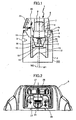
FIG. 1 is a vertical sectional view showing a dust collection device according to the present invention; -
FIG. 2 is a partial side view showing an upper portion of the dust collection device ofFIG. 1 ; -
FIG. 3 is an overall view showing the dust collection device ofFIG. 1 ; -
FIG. 4 is an overall view showing the dust collection device connected with an electric tool; -
FIG. 5 is a circuit diagram showing a control circuit of the dust collection device; -
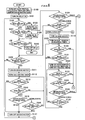
FIG. 6 is a flowchart illustrating a former portion of an operation by the dust collection device; and -
FIG. 7 is a flowchart illustrating a latter portion of the operation by the dust collection device shown inFIG. 6 . - A dust collection device according to an embodiment of the present invention will be described by referring to the accompanying drawings.
- Referring to
FIG. 1 , adust collector 1 has ahousing 100 including acylindrical tank 2 having aair inlet port 3 for containing dust, amain motor base 4 attached with amain motor cover 5 and ahead cover 6. Themain motor base 4 and thehead cover 6 are clamped by a clamp member (not shown) at an upside aperture of thetank 2. Thedust collector 1 includes an air suction device 7 arranged between themain motor base 4 and themotor cover 5 for aspirating powdery dust from theair inlet port 3, afilter unit 10 for capturing the aspirated powdery dust, adust removal device 14 for removing the powdery dust deposited to thefilter 13 and acontrol circuit 20 for controlling the air suction device 7 and thedust removal device 14, all of which are contained in thehousing 100. - The air suction device 7 has a
main motor 9 and asuction fan 8 driven by themain motor 9. The air suction device 7 takes in external air from theair inlet port 3 through anair intake port 4a formed in themain motor base 4. Additionally, the air suction device 7 guides the external air introduced in the device 7 through the discharge route defined by themain motor base 4, themain motor cover 5 and thehead cover 6, and discharges the external air through anexhaust port 4b to the outside of thehousing 100. - A
filter housing 11 is fixed and attached between the upside aperture of thetank 2 and themain motor base 4. Afilter device 10 is formed by thefilter housing 11, thefilter 13 for capturing dust and afilter cover 12, thefilter 13 and thefilter cover 12 being fitted to thefilter housing 11. Thefilter cover 12 is provided to prevent thefilter 13 from being crushed due to the negative pressure produced in the inside of thefilter 13 as a result of the operation of the air suction device 7. - The
dust removal device 14 is arranged in the space surrounded by thefilter housing 11 and thefilter 13. Thedust removal device 14 is fitted to a dustremoval device base 15 and has a DC power supply 37 (se-eFIG. 5 ), asecond motor 16 driven by theDC power supply 37, ananti-dust cover 19 for protecting thesecond motor 16 against powdery dust, areduction gear unit 17 coupled to the output shaft of thesecond motor 16 and adust removal member 18 arranged at the output shaft of thereduction gear unit 17 and driven by thesecond motor 16. Thedust removal member 18 removes the powdery dust deposited to thefilter 13 by vibrating thefilter 13, and clean thefilter 13. - The air suction device 7, the
filter 13, thefilter cover 12 and thedust removal device 11 are aligned on a vertical line M1 extending in the vertical direction, passing through each own center. The vertical line M1 is displaced from the center line M2 of thetank 2 to the opposite side of theair inlet port 3. - An
operation panel 21 and acontrol circuit 20 are provided to themain motor cover 5 at respective positions located above theair inlet port 3. As shown inFIG. 2 , theoperation panel 21 has aplug socket 24 for supplying electric power to an external device such as an electric tool 43 (seeFIG. 4 ), amain switch 26 for causing thedust collector 1 to start and stop operating, an interlocking mode/singlemode selection switch 27 and a dustremoval device switch 28. Note that themain switch 26 may have a function for selecting the dust collecting power. - As shown in
FIG. 3 , ahose 38, ahose connection handle 39, anextension tube 40 and a floorair inlet member 41 can be connected to theair inlet port 3. In this case, dust including fragments produced by cutting wood plates, stones, concrete or plaster boards can be aspirated with air. - As shown in
FIG. 4 , the plug of anelectric tool 43 can be inserted to theplug socket 24 of theoperation panel 21 and thedust discharge port 42 of anelectric tool 43 is connected to theair inlet port 3 by way of ahose 38. With this arrangement, the operation of thedust collector 1 can be interlocked with the operation of theelectric tool 43 to collect the powdery dust discharged from theelectric tool 43 into thetank 2. - Now, the
control circuit 20 will be described below by referring toFIG. 5 . Thepower source plug 22 includes a pair ofterminal pieces - The
main switch 26 includes twosub-switches plug 22 is connected to thesub-switch 26a, themain motor 9 and the mainmotor drive circuit 34 for controlling the rotary motion of themain motor 9. - The
plug 22 is connected to the input side of adiode bridge 23 for full wave rectification. Thesub-switch 26b and theDC power supply 37 are connected in series to the output side of thediode bridge 23. Arelay 29 is connected in parallel with thesub-switch 26b. The output side of theDC power supply 37 is connected to thesecond motor 16. - The
plug 22 is connected to theplug socket 24 that is connectable to theelectric tool 43. Thecurrent detector 25 detects the electric current flowing through theplug socket 24. - The
control circuit 20 includes amicrocomputer 36. The output port P02 of themicroprocessor 36 is connected to therelay 29 through arelay drive circuit 30. The opening and closing of therelay 29 is controlled according to the output signal from the output port P02. When theplug 22 is connected to a commercial power source and themain switch 26 is turned on, themain motor 9 starts rotating and electric power is supplied to theDC power supply 37 through thediode bridge 23 and the sub-switch 26b. When the mainswitch detection circuit 31 detects the on-status of themain switch 26, themicrocomputer 36 transmits an output signal to therelay drive circuit 30 to turn on therelay 29. Then, electric power is supplied to theDC power supply 37 from two routes. - When the
main switch 26 is turned off, the supply of electric power to themain motor 9 is stopped. On the other hand, the supply of electric power to theDC power supply 37 is continued as long as therelay 29 is on. Therefore, while electric power is supplied to theDC power supply 37, thesecond motor 16 for driving thedust removal device 14 can be operable. - The
microcomputer 36 confirms the operation of theelectric tool 43 connected to theplug socket 24 as follows: themicrocomputer 36 first receives the input signal indicating the detection of the electric current by thecurrent detector 25 at port Ain1 from thecurrent detection circuit 33 and then determines based on the input signal how theelectric tool 43 is operating. Theelectric tool 43 may be provided with a DC power source mounted therein. Therefore, themicrocomputer 36 may have a function of recognizing the electric current of the DC power source mounted in theelectric tool 43 and the electric current of the series commutator motor that is a drive source of theelectric tool 43. Alternatively, themicrocomputer 36 can determine the operating condition of theelectric tool 43 by detecting the power consumption of theelectric tool 43. - The
microcomputer 36 determines the operating condition of the air suction device 7 on the basis of the input signal indicating the voltage of themain switch 26 when themicrocomputer 36 receives the input signal at ports P13/INT through the mainswitch detection circuit 31. Alternatively, themicrocomputer 36 can determine the operating condition of the air suction device 7 by detecting the electric current flowing through themain motor 9, the number of revolutions-per unit time of themain motor 9, the internal pressure of thetank 2, the air flow rate in the hose or the wind velocity in the hose. - The suction device 7 continues operating due to the inertia of the
main motor 9 after the supply of electric power to themain motor 9 is stopped. Therefore, themicrocomputer 36 determines that the air suction device 7 actually stops operating, when the preset time has elapsed since the supply of electric power to themain motor 9 is stopped. Themicrocomputer 36 determines the stop of operation of the air suction device 7 in a similar manner when themain motor 9 is stopped by the stop signal of the air suction device 7 that is output from the port P01. The time period during which the air suction device 7 continues to operate due to the inertia is about 10 seconds. - The interlocking mode/single
mode selection switch 27 is a switch for selecting either an interlocking mode or a single mode of the air suction device 7. The single mode is a mode of operation where the air suction device 7 is operated by means of themain switch 26. The interlocking mode is a mode of operation where the air suction device 7 is operated in response to the operation of theelectric tool 43 connected to theplug socket 24. The interlocking mode/singlemode selection switch 27 has acommon terminal 27a and a normally open terminal 27b. The interlocking mode is selected when thecommon terminal 27a and the normally open terminal 27b are open. The single mode is selected when thecommon terminal 27a and the normally open terminal 27b are closed. In the interlocking mode, the air suction device 7 continues the operation thereof for a predetermined time, after theelectric tool 43 stops operating and then the operation of the suction device 7 is stopped. This arrangement is aimed at preventing the hose connected between theelectric tool 43 and thedust collector 1 from being clogged in an interlocking mode. - The dust
removal device switch 28 is a switch for operating thedust removal device 14. When the dustremoval device switch 28 is on, thedust removal device 14 is driven for a predetermined time to automatically remove the dust in thefilter 13 after the supply of electric power to the air suction device 7 is stopped. In other words, the dustremoval device switch 28 is effective only when themicrocomputer 36 determines that the operation of the air suction device 7 has been stopped. On the other hand, when themicrocomputer 36 determines that the operation of the air suction device 7 has not been stopped, thedust removal device 14 is not allowed to operate even if the dustremoval device switch 28 is on. The dust deposited to thefilter 13 is not removed due do the negative pressure until the air suction device 7 completely stops. Therefore, with this arrangement of theswitch 28, ineffective operation of thedust removal device 15 is prevented in order to prevent waste of electric power, and thefilter 13 is protected against damages. - The operation of the
main motor 9 can be switched by the output signal sent from the ports P00 and P01 of themicrocomputer 36. When a triac is used as an electric power control device for the mainmotor drive circuit 34, the suction power of the air suction device 7 can be changed by phase control of themain motor 9. Alternatively, the number of revolutions per unit time of themain motor 9 can be changed by connecting a pair of field windings to themain motor 9 and selectively operating the field windings. - The
second motor 16 is operated in accordance with the output signal generated from the port P03 of themicrocomputer 36 through the secondmotor drive circuit 35. Thesecond motor 16 can be softly started by driving the power control device in the secondmotor drive circuit 35 in a chopping mode. With this arrangement, the voltage fall of theDC power supply 37 due to the starting current of the second motor can be avoided. - The
dust collector 1 operates either in the single mode or in the interlocking mode. - In the single mode, the air suction device 7 is driven when the interlocking mode/single
mode selection switch 27 is switched to the single mode and themain switch 26 is turned on. When themain switch 26 is turned on, themicrocomputer 36 closes the contacts of therelay 29. When themain switch 26 is turned off subsequently, the supply of electric power to themain motor 9 is stopped. At this time, the supply of electric power to theDC power supply 37 is continued since therelay 29 is held on. - In the interlocking mode, the interlocked mode/single
mode selection switch 27 is switched to the interlocking mode and theelectric tool 43 is connected to theplug socket 24. When themain switch 26 is turned on and themicrocomputer 36 determines that theelectric tool 43 starts operating, the air suction device 7 starts to operate. At this time, themicrocomputer 36 generates a signal from the ports P00 and P01 to drive themain motor 9 through the mainmotor drive circuit 34. Additionally, when themain switch 26 is turned on, themicrocomputer 36 turns on therelay 29. - Thereafter, when the
electric tool 43 is stopped and the electric current flowing through theplug socket 24 disappears, themicrocomputer 36 determines that theelectric tool 43 has stopped. Then, after the elapse of a predetermined time, themicrocomputer 36 generates a signal from the ports P00 and P01 to the mainmotor drive circuit 34 to stop the operation of themain motor 9. Since themain switch 26 remains on at this time, the supply of electric power to theDC power supply 37 is continued. - The
microcomputer 36 monitors the operation time of the air suction device 7, and determines that a dust removal operation is necessary if the operation time period of the air suction device 7 exceeds the predetermined time. On the other hand, themicrocomputer 36 determines that the dust removal operation is not necessary if the operation time period of the air suction device 7 does not exceed the predetermined time. When the air suction device 7 stops, themicrocomputer 36 drives thesecond motor 16 for several seconds to remove the dust deposited to thefilter 13 by using thedust removal member 18, if dust removal for thefilter 13 is necessary. Themicrocomputer 36 does not drive thesecond motor 16 when the dust removal is not necessary. - The
dust removal device 14 is operated when the air suction device 7 is at rest. Therefore, when themain switch 26 is turned off, the on-status of therelay 29 is maintained for a while so that electric power is kept supplying to theDC power supply 37 to keep thedust removal device 14 ready for operation. Ten and several minutes is selected as the time period in which the on-status of therelay 29 is maintained after the stop of the power supply to the air suction device 7, considering the condition where the user manually operates thedust removal device 14. This time period corresponds to the self-holding time period of therelay 29. When the self-maintaining time period elapses, therelay 29 is turned off and the standby power of thedust collector 1 becomes practically disappeared. - Now, the operation of the
dust collector 1 will be described below by referring toFIGS. 6 and7 . - When the
power supply plug 22 of thedust collector 1 is connected to a commercial power source and themain switch 26 is turned on, electric power is supplied to thecontrol circuit 20 and themicrocomputer 36 turns off a dust removal evaluation timer and turns off a dust removal effective flag (S100). The dust removal evaluation timer is a timer for measuring the operation time of themain motor 9. The dust removal evaluation timer is used to determine whether the operation time of themain motor 9 exceed a predetermined time period such as 10 minutes. When a process for turning off themotor 9 has not performed within the predetermined time period, the dust removal effective flag is changed from off to on. Then, themicrocomputer 36 turns on the relay 29 (S101). Themicrocomputer 36 examines the status of the main switch 26 (S102). If themain switch 26 is on, themicrocomputer 36 turns off a 15 minute timer (S103). The 15 minute timer is a timer for measuring the time after the power supply to themain motor 9 is stopped, in other words, the power supply suspension time. The dust removal effective flag indicates whether dust removal should be performed or not. Then, themicrocomputer 36 determines whether the operation mode is a single mode or not (S104). - If the operation mode is the interlocking mode (S104: interlocking), the
microcomputer 36 then determines whether the plug socket current flowing through theplug socket 24 is more than or equal to 1A or not (S105). If the plug socket current is less than 1A (S105: NO), themicrocomputer 36 examines the condition of the dust removal device switch 28 (S106). If the dustremoval device switch 28 is off (S106: NO), themicrocomputer 36 returns to Step S102. The plug socket current of 1A is the reference value for determining whether theelectric tool 43 connected to theplug socket 24 is operating or not. Therefore, if the plug socket current is more than or equal to 1A, themicrocomputer 36 determines that theelectric tool 43 is operating. On the other hand, if the plug socket current is lower than 1A, themicrocomputer 36 determines that theelectric tool 43 is at rest. - Then, if the
main switch 26 is off in Step S102 (S102: NO), themicrocomputer 36 proceeds to the next step, or Step S107, where themicrocomputer 36 determines whether the 15 minute timer is on or off. If the 15 minute timer is off (S107: NO), themicrocomputer 36 turns off the 15 minute timer (S108). In Step S109, themicrocomputer 36 determines whether the power supply suspension time is more than or equal to 15 minutes or not. If the power supply suspension time is less than 15 minutes (S109: NO), themicrocomputer 36 proceeds to Step S106. On the other hand, if the power supply suspension time is determined to be more than or equal to 15 minutes (S109: YES), themicrocomputer 36 turns off therelay 29 and stops the operation of thedust collector 1 in Step S110. - The
microcomputer 36 determines in Step S106 whether the dustremoval device switch 28 is on or off. At this case, the supply of electric power to themain motor 9 is stopped. Accordingly, the dustremoval device switch 28 is effective for operating the dust removal device. If the dustremoval device switch 28 is turned on (S106: YES), the dust removal device can be started. Therefore, themicrocomputer 36 starts thesecond motor 16 in Step S111 and then starts a 3 second timer in Step S112. The 3 second time is a timer for measuring the operation time of thedust removal device 14. - Then, the
microcomputer 36 sequentially determines whether the operation time of thedust removal device 14 exceeds 3 seconds or not (S113), whether themain switch 26 is on or not (S114), whether the current operation mode is an interlocking mode or a single mode (S115), and whether the plug socket current is more than or equal to 1A or not (S116) when the current mode of operation is an interlocking mode. The above steps are a process for driving thedust removal device 14 for 3 seconds and then stopping thedust removal device 14. - While the steps S113-S116 are processed, if it is determined that the
main switch 26 is on (S114: YES) and that the current mode of operation is a single mode (S115: YES), themicrocomputer 36 proceeds to Step S117, where themicrocomputer 36 stops thesecond motor 16. On the other hand, if the current mode of operation is the interlocking mode (S115: interlocking), and the plug socket current is more than or equal to 1A (S116: YES), themicrocomputer 36 proceeds to Step S117, where themicrocomputer 36 stops thesecond motor 16. With these steps, the operation of thedust removal device 14 can be suspended when the air suction device 7 starts operating while thesecond motor 16 is in operation. When the operation time of thedust removal device 14 exceeds 3 seconds (S113: YES), themicrocomputer 36 stops the rotation of the second motor 16 (S117). - On the other hand, if the
microcomputer 36 determines in Step S102 that themain switch 26 is on, that the current mode is the interlocking mode in Step S104 (S104: interlocking) through Step S103 and that the plug socket current is more than or equal to 1A in Step S105 (S105: YES), themicrocomputer 36 proceeds to Step S118. The subsequent process is a process for the interlocking mode. Then, themicrocomputer 36 turns on themain motor 9 in Step S118 and starts the dust removal evaluation timer in Step S119. Themicrocomputer 36 determines whether themain switch 26 is on or off (S120) and whether the plug socket current is more than or equal to 1A or not (S121). - If the
microcomputer 36 determines in Step S120 that themain switch 26 is off, themicrocomputer 36 proceeds to Step S132. If themicrocomputer 36 determines in Step S121 that the plug socket current is less than 1A, themicrocomputer 36 proceeds to Step S122, where the microcomputer stops the dust removal evaluation timer and starts a five second timer. The five second timer is a timer for measuring the operation time during which the air suction device 7 is driven after stopping theelectric tool 43. Themicrocomputer 36 determines whether the reading of the five second timer exceeds five seconds or not in S123, whether themain switch 26 is on or not in S124, whether the current mode of operation is a single mode or an interlocking mode in S125 and whether the plug socket current is not less than 1A or not in S126. The steps from S123 to S126 are a process for waiting for the elapse of the preset time from the time when the air suction device 7 starts operating and to the time when the air suction device 7 stops operating in the interlocking mode. - If the
microcomputer 36 determines in Step S104 that the current mode of operation is the single mode, themicrocomputer 36 proceeds to Step S127 (FIG. 7 ). The subsequent process is a process for a single mode. Themicrocomputer 36 turns on themain motor 9 in S127 and starts the dust removal evaluation timer in S128. Then, themicrocomputer 36 determines whether themain switch 26 is_on or off in Step S129 and which the current mode of operation is in Step S130. The steps of S129 and S130 are a process for determining whether themain switch 26 for stopping the air suction device 7 is off or not and whether the operation mode is switched or not. When themicrocomputer 36 determines in Step S129 that themain switch 26 is turned off (S129: YES), themicrocomputer 36 proceeds to Step S132. If themicrocomputer 36 determines in Step S130 that the current mode of operation has been switched to the interlocking mode (S130: interlocking), the microcomputer proceeds to Step S131, where the microcomputer determines whether the plug socket current is more than or equal to 1A or not. When the plug socket current is not less than 1A (S131: YES), themicrocomputer 36 proceeds to Step S118. On the other hand, when the plug socket current is less than 1A (S131: NO), the microcomputer proceeds to Step S132. - The following steps from Step S132 are a process for stopping the air suction device 7. The
microcomputer 36 turns off themain motor 9 in Step S132, turns off the dust removal timer, and starts the five second timer in Step S133. Then, in Step S134, themicrocomputer 36 starts a 9 second timer. The 9 second timer is a timer for measuring the time elapsed from the time when the supply of electric power to themain motor 9 is stopped to the time when the internal pressure of thefilter 13 becomes equal to the atmospheric pressure from the previous negative pressure. Then, themicrocomputer 36 determines whether the reading of the 9 second timer exceeds 9 seconds or not in Step S135 and whether themain switch 26 is on or off in Step S136. When the microcomputer determines that themain switch 26 is not on in Step S136, themicrocomputer 36 returns to Step S135. - On the other hand, when the microcomputer determines in Step S136 that the
main switch 26 is on, themicrocomputer 36 determines in Step S138 whether the current mode of operation is a single mode or not. If themicrocomputer 36 determines in Step S138 that the current mode of operation is not the single mode, the microcomputer proceeds to Step S139, where the microcomputer measures the plug socket current. When the plug socket current is less than 1A (S139: NO), themicrocomputer 36 returns to Step S135. The steps from S135 to S139 are a process for standing by thedust removal device 14 until the internal pressure of the filter restores the atmospheric pressure. - If the
microcomputer 36 determines in Step S135 that the reading of the 9 second timer exceeds 9 seconds (S135: YES), the microcomputer proceeds to Step S140, where the microcomputer executes an automatic dust removal process. When the microcomputer determines in Step S136 that themain switch 26 is on and in Step S138 that the current mode of operation is a single mode (S138: YES), themicrocomputer 36 proceeds to Step S148. However, when the microcomputer determines in Step S138 that the current mode of operation is the interlocking mode (S138: interlocking) and in Step S139 that the plug socket current is more than or equal to 1A (S139: YES), themicrocomputer 36 also proceeds to Step S148. - The following process starting from Step S140 is the automatic dust removal process for removing dust form the
filter 13 to clean thefilter 13. Themicrocomputer 36 examines the dust removal effective flag in Step S140. If the dust removal effective flag is not ON, themicrocomputer 36 returns to Step S102 and does not execute the automatic dust removal operation. On the other hand, if the dust removal effective flag is ON, themicrocomputer 36 starts rotating thesecond motor 16 in Step S141 and also starts a 3 second timer in Step S142. The 3 second timer is a timer for measuring the operation time of thedust removal device 14. In this embodiment, the operation time of thedust removal device 14 is set as 3 seconds. Then, themicrocomputer 36 determines whether the reading of the 3 second timer exceeds 3 seconds or not in Step S143. If themicrocomputer 36 determines in Step S143 that the reading of the 3 second timer exceeds 3 seconds (S143: YES), the microcomputer proceeds to Step S147, where the microcomputer stops the rotation of thesecond motor 16 to finish the automatic dust removal process. - On the other hand, if the
microcomputer 36 determines in Step S143 that the reading of the 3 second timer is less than 3 seconds (S143: NO), the microcomputer determines whether themain switch 26 is on or off in Step S144. when themain switch 26 is off (S144: NO), themicrocomputer 36 returns to Step S143. On the other hand, when themain switch 26 is on (S144: YES), themicrocomputer 36 examines the current mode of operation in Step S145. If the current mode of operation is the interlocking mode (S145: interlocking), themicrocomputer 36 determines whether the plug socket current is more than or equal to 1A or not in Step S146. If themain switch 26 is turned on, or the current mode of operation is switched to the interlocking mode and the operation of theelectric tool 43 is confirmed while thedust removal device 14 is automatically operating, themicrocomputer 36 proceeds to Step S147, where the microcomputer stops thesecond motor 16 to finish the automatic dust removal process. - After S147, the
microcomputer 36 turns off the dust removal effective flag in Step S148 and returns to Step S102. - A swinging vibrator may be used as the drive source of the
dust removal member 18 in other embodiments. - According to the present invention, the dust removal device is automatically activated when the air suction device operates for a predetermined time period and stops operating. Accordingly, dust is reliably removed from the filter device. A reduction in the suction force can be prevented effectively.
- The dust removal device automatically starts operating only when the operation time of the air suction device exceeds a predetermined time. In other words, the filter is cleaned by the dust removal process when the filter device is considered to be significantly clogged. Thus, the dust removal device can enjoy a prolonged service life because the dust removal device is operated only in limited occasions.
- The dust removal device starts operating when a predetermined time has elapsed since the supply of electric power to the air suction device is stopped. This structure ensures that dust can be removed from the filter after the internal pressure of the filter restores the atmospheric pressure. Therefore, dust can be removed efficiently from the filter.
- It is understood that the foregoing description and accompanying drawings set forth the embodiments of the invention at the present time. Various modifications, additions and alternative designs will, of course, become apparent to those skilled in the art in light of the foregoing teachings without departing from the spirit and scope of the disclosed invention. Thus, it should be appreciated that the invention is not limited to the disclosed embodiments but may be practiced within the full scope of the appended claims.
Claims (8)
- A dust collection device comprising:a tank (2) having an air inlet (3) for accommodating dust;a suction unit (7) for aspirating the dust through the air inlet (3);a filtering unit (10) for capturing the dust through the air inlet (3);a dust removal unit (14) for removing the dust from the filtering unit (10);a first detection unit (31) for detecting the operational state of the suction unit (7); anda control unit (20) for controlling the suction unit (7) and the dust removal unit (14),wherein the control unit (20) activates the dust removal unit (14), when the first detection unit (31) detects that the suction unit (7) operates for a first predetermined time period and then stops operating.
- The device of claim 1, further comprising a switching unit (26) for turning on and off the suction unit (7), wherein the control unit (20) activates the dust removal unit (14), when the first detection unit (31) detects that the suction unit (7) operates for more than the first predetermined time period and the switching unit (26) then turns off the suction unit (7).
- The device of claim 2, wherein the control unit (20) activates the suction unit (7) a second predetermined time period after the switching unit (26) turns off the suction unit (7).
- The device of claim 1, further comprising:a receptacle unit (24) connectable to an external device (43) for feeding electric power to the external device (43); anda second detection unit (33) for detecting the operational state of the external device (43),wherein the control unit (20) activates the dust removal unit (14) when the second detection unit (33) detects that the external device (43) stops operating.
- The device of claim 4, wherein the control unit (20) activates the suction unit (7) when the second detection unit (33) detects that the external device (43) connected to the receptacle unit (24) operates for a third predetermined time period and then stops operating.
- The device of claim 4, wherein the control unit (20) activates the dust removal unit (14) a forth predetermined time period after the second detection unit (33) detects that the external device (43) connected to the external device (43) stops operating.
- The device of claim 1, wherein the dust removal unit (14) operates for a fifth predetermined time period and then stops operating.
- The device of claim 1, wherein
the tank (2) has a cylindrical shape,
the suction unit (7) is provided above the tank (2),
the filtering unit (10) includes a filter member (13) provided inside of the tank (2),
the dust removal unit (14) includes a dust removal member (18) and a motor for driving the dust removal member (18), the dust removal member (18) being provided inside of the filter member (13) and rotatable to move the filter member (13).
Applications Claiming Priority (1)
| Application Number | Priority Date | Filing Date | Title |
|---|---|---|---|
| JP2007071641A JP5185551B2 (en) | 2007-03-19 | 2007-03-19 | Dust collector |
Publications (3)
| Publication Number | Publication Date |
|---|---|
| EP1972248A2 true EP1972248A2 (en) | 2008-09-24 |
| EP1972248A3 EP1972248A3 (en) | 2011-08-03 |
| EP1972248B1 EP1972248B1 (en) | 2016-05-18 |
Family
ID=39432605
Family Applications (1)
| Application Number | Title | Priority Date | Filing Date |
|---|---|---|---|
| EP08005063.6A Not-in-force EP1972248B1 (en) | 2007-03-19 | 2008-03-18 | Dust collection device |
Country Status (3)
| Country | Link |
|---|---|
| US (1) | US7871463B2 (en) |
| EP (1) | EP1972248B1 (en) |
| JP (1) | JP5185551B2 (en) |
Cited By (4)
| Publication number | Priority date | Publication date | Assignee | Title |
|---|---|---|---|---|
| EP2644073A1 (en) * | 2012-03-27 | 2013-10-02 | ELECTROSTAR GmbH | Sucker |
| EP2937031A1 (en) * | 2014-04-23 | 2015-10-28 | HILTI Aktiengesellschaft | Mode change |
| CN107205605A (en) * | 2015-12-18 | 2017-09-26 | 东芝生活电器株式会社 | Dust collect plant |
| EP3409172A1 (en) * | 2017-05-31 | 2018-12-05 | Conta S.R.O | Self-cleaning vacuum cleaner |
Families Citing this family (15)
| Publication number | Priority date | Publication date | Assignee | Title |
|---|---|---|---|---|
| JP4747850B2 (en) * | 2006-01-20 | 2011-08-17 | 日立工機株式会社 | Dust collector |
| US8152602B2 (en) * | 2009-01-30 | 2012-04-10 | JPL Global, LLC | Grinder and core drill with dust collection |
| KR101352272B1 (en) * | 2009-07-06 | 2014-01-17 | 엘지전자 주식회사 | A robot cleaner |
| US9221110B2 (en) * | 2009-10-02 | 2015-12-29 | JPL Global, LLC | Power saw apparatus with integrated dust collector |
| US20110126716A1 (en) * | 2009-11-30 | 2011-06-02 | Mao-Nan Cheng | Dust-collecting apparatus |
| JP5539020B2 (en) * | 2010-05-20 | 2014-07-02 | 株式会社マキタ | Cutting tool dust collector |
| TR201908589T4 (en) * | 2013-11-26 | 2019-07-22 | Koninklijke Philips Nv | Air filter monitoring. |
| USD742081S1 (en) | 2014-01-15 | 2015-10-27 | Milwaukee Electric Tool Corporation | Dust collector |
| USD741557S1 (en) | 2014-01-15 | 2015-10-20 | Milwaukee Electric Tool Corporation | Dust collector |
| JP7098318B2 (en) * | 2017-12-21 | 2022-07-11 | 株式会社マキタ | Dust collector for power tools and power tools |
| US11235433B2 (en) | 2017-12-22 | 2022-02-01 | Milwaukee Electric Tool Corporation | Dust collector with filter cleaning mechanism |
| CN215968574U (en) | 2018-11-19 | 2022-03-08 | 米沃奇电动工具公司 | Dust collector suitable for use with a hand held power tool |
| JP7222776B2 (en) * | 2019-03-26 | 2023-02-15 | 株式会社マキタ | Dust collection attachment and dust collection system for power tools |
| JP7340942B2 (en) * | 2019-03-26 | 2023-09-08 | 株式会社マキタ | Power tool dust collection system |
| CN219665906U (en) | 2020-03-25 | 2023-09-12 | 米沃奇电动工具公司 | Dust collector for use with a hand-held power tool |
Citations (1)
| Publication number | Priority date | Publication date | Assignee | Title |
|---|---|---|---|---|
| JP2006325820A (en) | 2005-05-25 | 2006-12-07 | Toshiba Tec Corp | Electric cleaner |
Family Cites Families (35)
| Publication number | Priority date | Publication date | Assignee | Title |
|---|---|---|---|---|
| JPS481197Y1 (en) * | 1969-11-19 | 1973-01-12 | ||
| US3667084A (en) * | 1970-10-23 | 1972-06-06 | Dynamics Corp America | Lightweight vacuum cleaner |
| US3695006A (en) * | 1970-10-23 | 1972-10-03 | Dynamics Corp America | Vacuum cleaner |
| JPS535992Y2 (en) * | 1971-04-28 | 1978-02-15 | ||
| US3906756A (en) * | 1974-01-15 | 1975-09-23 | Aubra N Bone | Drapery and sheet material cleaning machine |
| JPS538166U (en) * | 1976-07-07 | 1978-01-24 | ||
| US4545794A (en) * | 1981-11-13 | 1985-10-08 | Sanyo Electric Co., Ltd. | Vacuum cleaner |
| JPS60212140A (en) * | 1984-04-05 | 1985-10-24 | 松下電器産業株式会社 | Dust remover of central cleaner |
| US5240484A (en) * | 1987-07-21 | 1993-08-31 | Southwest Manufacturers & Distributors, Inc. | Antimicrobial vacuum cleaner bag |
| JPH02132208A (en) * | 1988-11-14 | 1990-05-21 | Toyota Autom Loom Works Ltd | Dust scraper for floor surface cleaning vehicle |
| GB8917525D0 (en) * | 1989-08-01 | 1989-09-13 | Lucas Ind Plc | Power control circuit |
| US5143528A (en) * | 1990-02-14 | 1992-09-01 | Challenge Industries | Lint collector |
| US5352255A (en) * | 1993-04-05 | 1994-10-04 | Taft Andrew A | Noise maker for air filter |
| JP3342943B2 (en) * | 1994-01-28 | 2002-11-11 | アマノ株式会社 | Filter dust remover for dust collector |
| JPH09843A (en) * | 1995-06-16 | 1997-01-07 | Makita Corp | Dust collector |
| US6117200A (en) * | 1996-04-15 | 2000-09-12 | Tennant Company | Electromagnetic filter cleaning system |
| US5914453A (en) * | 1996-11-25 | 1999-06-22 | James; Terry Lynn | Air handler filter monitoring apparatus |
| DE29822389U1 (en) * | 1998-12-16 | 1999-03-04 | Electrostar Schöttle GmbH & Co, 73262 Reichenbach | Power tool with dust extraction device |
| EP1050332A3 (en) * | 1999-05-04 | 2001-05-23 | Simatelex Manufactory Company Limited | Air purifier |
| US6228155B1 (en) * | 1999-08-24 | 2001-05-08 | Kuo Cheng Tai | Automatic detection and warning device of filtering net in air conditioner |
| WO2002017766A2 (en) * | 2000-09-01 | 2002-03-07 | Royal Appliance Mfg. Co. | Bagless canister vacuum cleaner |
| KR100583567B1 (en) * | 2000-12-13 | 2006-05-26 | 엘지전자 주식회사 | Filter of fixing device for vacuum cleaner |
| JP2002326119A (en) * | 2001-04-26 | 2002-11-12 | Hitachi Koki Co Ltd | Dust collecting device of portable electric tool |
| JP3825759B2 (en) * | 2002-06-17 | 2006-09-27 | 株式会社リコー | Powder recovery apparatus, developing apparatus, image forming apparatus, and powder recovery method |
| JP2004129989A (en) * | 2002-10-15 | 2004-04-30 | Matsushita Electric Ind Co Ltd | Vacuum cleaner |
| CN2693166Y (en) * | 2002-10-15 | 2005-04-20 | 松下电器产业株式会社 | Electric dust collector |
| JP4110929B2 (en) * | 2002-11-05 | 2008-07-02 | 松下電器産業株式会社 | Electric vacuum cleaner |
| JP2004201919A (en) * | 2002-12-25 | 2004-07-22 | Matsushita Electric Ind Co Ltd | Electric cleaner |
| JP3889364B2 (en) * | 2003-01-15 | 2007-03-07 | 東芝テック株式会社 | Electric vacuum cleaner |
| JP2004283344A (en) * | 2003-03-20 | 2004-10-14 | Toshiba Tec Corp | Vacuum cleaner and its operation method |
| JP2004344582A (en) * | 2003-05-26 | 2004-12-09 | Toshiba Tec Corp | Vacuum cleaner |
| JP4107171B2 (en) * | 2003-06-06 | 2008-06-25 | 松下電器産業株式会社 | Electric vacuum cleaner |
| US7303613B2 (en) * | 2003-12-11 | 2007-12-04 | Euro-Pro Operating, Llc | Filter sensor and indicator for vacuum cleaners |
| JP2007050042A (en) * | 2005-08-16 | 2007-03-01 | Matsushita Electric Ind Co Ltd | Vacuum cleaner |
| JP2007050360A (en) * | 2005-08-18 | 2007-03-01 | Ryobi Ltd | Dust collector |
-
2007
- 2007-03-19 JP JP2007071641A patent/JP5185551B2/en active Active
-
2008
- 2008-03-18 EP EP08005063.6A patent/EP1972248B1/en not_active Not-in-force
- 2008-03-19 US US12/050,971 patent/US7871463B2/en not_active Expired - Fee Related
Patent Citations (1)
| Publication number | Priority date | Publication date | Assignee | Title |
|---|---|---|---|---|
| JP2006325820A (en) | 2005-05-25 | 2006-12-07 | Toshiba Tec Corp | Electric cleaner |
Cited By (7)
| Publication number | Priority date | Publication date | Assignee | Title |
|---|---|---|---|---|
| EP2644073A1 (en) * | 2012-03-27 | 2013-10-02 | ELECTROSTAR GmbH | Sucker |
| EP2937031A1 (en) * | 2014-04-23 | 2015-10-28 | HILTI Aktiengesellschaft | Mode change |
| CN107205605A (en) * | 2015-12-18 | 2017-09-26 | 东芝生活电器株式会社 | Dust collect plant |
| EP3391798A4 (en) * | 2015-12-18 | 2019-09-04 | Toshiba Lifestyle Products & Services Corporation | Dust collector |
| US11096533B2 (en) | 2015-12-18 | 2021-08-24 | Toshiba Lifestyle Products & Services Corporation | Dust-collecting device |
| EP3409172A1 (en) * | 2017-05-31 | 2018-12-05 | Conta S.R.O | Self-cleaning vacuum cleaner |
| CN108968804A (en) * | 2017-05-31 | 2018-12-11 | 康塔有限公司 | Automatically cleaning vacuum cleaner |
Also Published As
| Publication number | Publication date |
|---|---|
| US7871463B2 (en) | 2011-01-18 |
| EP1972248A3 (en) | 2011-08-03 |
| US20080229719A1 (en) | 2008-09-25 |
| JP5185551B2 (en) | 2013-04-17 |
| JP2008229463A (en) | 2008-10-02 |
| EP1972248B1 (en) | 2016-05-18 |
Similar Documents
| Publication | Publication Date | Title |
|---|---|---|
| EP1972248B1 (en) | Dust collection device | |
| JP2007190302A (en) | Dust collector | |
| CN116322452A (en) | Cleaning apparatus including vacuum cleaner and docking station and control method thereof | |
| KR20060112420A (en) | A dust collector for vacuum clearner | |
| JPH07236514A (en) | Cleaning device of shaver head of dry type shaver device | |
| WO2013179715A1 (en) | Charging-type electric vacuum cleaner | |
| JP2007245019A (en) | Dust collector | |
| JP2000291999A (en) | Air conditioner | |
| CN113616126A (en) | Recycling bin and cleaning equipment | |
| JP2007190303A (en) | Dust collector | |
| KR101945259B1 (en) | Outdoor electrostatic dust collector and controlling method thereof | |
| JP2004283344A (en) | Vacuum cleaner and its operation method | |
| KR20140046741A (en) | Cartridge type movable dust collector | |
| JP3889364B2 (en) | Electric vacuum cleaner | |
| KR101295162B1 (en) | Air washer | |
| JP2004215898A (en) | Vacuum cleaner | |
| JP2007190527A (en) | Dust collector | |
| JP2009165749A (en) | Dust collector | |
| JP2007190304A (en) | Dust collector | |
| JP3120097B2 (en) | Negative ion generator | |
| JP4726763B2 (en) | Vacuum cleaner | |
| CN220554475U (en) | Suction apparatus | |
| JP2004344582A (en) | Vacuum cleaner | |
| CN215305589U (en) | Recycling bin and cleaning equipment | |
| JP2004283345A (en) | Vacuum cleaner |
Legal Events
| Date | Code | Title | Description |
|---|---|---|---|
| PUAI | Public reference made under article 153(3) epc to a published international application that has entered the european phase |
Free format text: ORIGINAL CODE: 0009012 |
|
| AK | Designated contracting states |
Kind code of ref document: A2 Designated state(s): AT BE BG CH CY CZ DE DK EE ES FI FR GB GR HR HU IE IS IT LI LT LU LV MC MT NL NO PL PT RO SE SI SK TR |
|
| AX | Request for extension of the european patent |
Extension state: AL BA MK RS |
|
| 17P | Request for examination filed |
Effective date: 20100331 |
|
| PUAL | Search report despatched |
Free format text: ORIGINAL CODE: 0009013 |
|
| AK | Designated contracting states |
Kind code of ref document: A3 Designated state(s): AT BE BG CH CY CZ DE DK EE ES FI FR GB GR HR HU IE IS IT LI LT LU LV MC MT NL NO PL PT RO SE SI SK TR |
|
| AX | Request for extension of the european patent |
Extension state: AL BA MK RS |
|
| RIC1 | Information provided on ipc code assigned before grant |
Ipc: A47L 9/19 20060101ALI20110629BHEP Ipc: A47L 9/28 20060101ALI20110629BHEP Ipc: A47L 9/20 20060101AFI20110629BHEP |
|
| AKX | Designation fees paid |
Designated state(s): AT BE BG CH CY CZ DE DK EE ES FI FR GB GR HR HU IE IS IT LI LT LU LV MC MT NL NO PL PT RO SE SI SK TR |
|
| 17Q | First examination report despatched |
Effective date: 20131108 |
|
| GRAP | Despatch of communication of intention to grant a patent |
Free format text: ORIGINAL CODE: EPIDOSNIGR1 |
|
| INTG | Intention to grant announced |
Effective date: 20151127 |
|
| INTG | Intention to grant announced |
Effective date: 20151208 |
|
| GRAS | Grant fee paid |
Free format text: ORIGINAL CODE: EPIDOSNIGR3 |
|
| GRAA | (expected) grant |
Free format text: ORIGINAL CODE: 0009210 |
|
| AK | Designated contracting states |
Kind code of ref document: B1 Designated state(s): AT BE BG CH CY CZ DE DK EE ES FI FR GB GR HR HU IE IS IT LI LT LU LV MC MT NL NO PL PT RO SE SI SK TR |
|
| REG | Reference to a national code |
Ref country code: GB Ref legal event code: FG4D |
|
| REG | Reference to a national code |
Ref country code: CH Ref legal event code: EP |
|
| REG | Reference to a national code |
Ref country code: IE Ref legal event code: FG4D Ref country code: AT Ref legal event code: REF Ref document number: 799658 Country of ref document: AT Kind code of ref document: T Effective date: 20160615 |
|
| REG | Reference to a national code |
Ref country code: DE Ref legal event code: R096 Ref document number: 602008044272 Country of ref document: DE |
|
| REG | Reference to a national code |
Ref country code: NL Ref legal event code: MP Effective date: 20160518 |
|
| REG | Reference to a national code |
Ref country code: LT Ref legal event code: MG4D |
|
| PG25 | Lapsed in a contracting state [announced via postgrant information from national office to epo] |
Ref country code: FI Free format text: LAPSE BECAUSE OF FAILURE TO SUBMIT A TRANSLATION OF THE DESCRIPTION OR TO PAY THE FEE WITHIN THE PRESCRIBED TIME-LIMIT Effective date: 20160518 Ref country code: NO Free format text: LAPSE BECAUSE OF FAILURE TO SUBMIT A TRANSLATION OF THE DESCRIPTION OR TO PAY THE FEE WITHIN THE PRESCRIBED TIME-LIMIT Effective date: 20160818 Ref country code: NL Free format text: LAPSE BECAUSE OF FAILURE TO SUBMIT A TRANSLATION OF THE DESCRIPTION OR TO PAY THE FEE WITHIN THE PRESCRIBED TIME-LIMIT Effective date: 20160518 Ref country code: LT Free format text: LAPSE BECAUSE OF FAILURE TO SUBMIT A TRANSLATION OF THE DESCRIPTION OR TO PAY THE FEE WITHIN THE PRESCRIBED TIME-LIMIT Effective date: 20160518 |
|
| REG | Reference to a national code |
Ref country code: AT Ref legal event code: MK05 Ref document number: 799658 Country of ref document: AT Kind code of ref document: T Effective date: 20160518 |
|
| PG25 | Lapsed in a contracting state [announced via postgrant information from national office to epo] |
Ref country code: GR Free format text: LAPSE BECAUSE OF FAILURE TO SUBMIT A TRANSLATION OF THE DESCRIPTION OR TO PAY THE FEE WITHIN THE PRESCRIBED TIME-LIMIT Effective date: 20160819 Ref country code: PT Free format text: LAPSE BECAUSE OF FAILURE TO SUBMIT A TRANSLATION OF THE DESCRIPTION OR TO PAY THE FEE WITHIN THE PRESCRIBED TIME-LIMIT Effective date: 20160919 Ref country code: ES Free format text: LAPSE BECAUSE OF FAILURE TO SUBMIT A TRANSLATION OF THE DESCRIPTION OR TO PAY THE FEE WITHIN THE PRESCRIBED TIME-LIMIT Effective date: 20160518 Ref country code: LV Free format text: LAPSE BECAUSE OF FAILURE TO SUBMIT A TRANSLATION OF THE DESCRIPTION OR TO PAY THE FEE WITHIN THE PRESCRIBED TIME-LIMIT Effective date: 20160518 Ref country code: SE Free format text: LAPSE BECAUSE OF FAILURE TO SUBMIT A TRANSLATION OF THE DESCRIPTION OR TO PAY THE FEE WITHIN THE PRESCRIBED TIME-LIMIT Effective date: 20160518 |
|
| PG25 | Lapsed in a contracting state [announced via postgrant information from national office to epo] |
Ref country code: IT Free format text: LAPSE BECAUSE OF FAILURE TO SUBMIT A TRANSLATION OF THE DESCRIPTION OR TO PAY THE FEE WITHIN THE PRESCRIBED TIME-LIMIT Effective date: 20160518 |
|
| PG25 | Lapsed in a contracting state [announced via postgrant information from national office to epo] |
Ref country code: RO Free format text: LAPSE BECAUSE OF FAILURE TO SUBMIT A TRANSLATION OF THE DESCRIPTION OR TO PAY THE FEE WITHIN THE PRESCRIBED TIME-LIMIT Effective date: 20160518 Ref country code: EE Free format text: LAPSE BECAUSE OF FAILURE TO SUBMIT A TRANSLATION OF THE DESCRIPTION OR TO PAY THE FEE WITHIN THE PRESCRIBED TIME-LIMIT Effective date: 20160518 Ref country code: CZ Free format text: LAPSE BECAUSE OF FAILURE TO SUBMIT A TRANSLATION OF THE DESCRIPTION OR TO PAY THE FEE WITHIN THE PRESCRIBED TIME-LIMIT Effective date: 20160518 Ref country code: SK Free format text: LAPSE BECAUSE OF FAILURE TO SUBMIT A TRANSLATION OF THE DESCRIPTION OR TO PAY THE FEE WITHIN THE PRESCRIBED TIME-LIMIT Effective date: 20160518 Ref country code: DK Free format text: LAPSE BECAUSE OF FAILURE TO SUBMIT A TRANSLATION OF THE DESCRIPTION OR TO PAY THE FEE WITHIN THE PRESCRIBED TIME-LIMIT Effective date: 20160518 |
|
| REG | Reference to a national code |
Ref country code: DE Ref legal event code: R097 Ref document number: 602008044272 Country of ref document: DE |
|
| PG25 | Lapsed in a contracting state [announced via postgrant information from national office to epo] |
Ref country code: AT Free format text: LAPSE BECAUSE OF FAILURE TO SUBMIT A TRANSLATION OF THE DESCRIPTION OR TO PAY THE FEE WITHIN THE PRESCRIBED TIME-LIMIT Effective date: 20160518 Ref country code: BE Free format text: LAPSE BECAUSE OF FAILURE TO SUBMIT A TRANSLATION OF THE DESCRIPTION OR TO PAY THE FEE WITHIN THE PRESCRIBED TIME-LIMIT Effective date: 20160518 Ref country code: PL Free format text: LAPSE BECAUSE OF FAILURE TO SUBMIT A TRANSLATION OF THE DESCRIPTION OR TO PAY THE FEE WITHIN THE PRESCRIBED TIME-LIMIT Effective date: 20160518 |
|
| PLBE | No opposition filed within time limit |
Free format text: ORIGINAL CODE: 0009261 |
|
| STAA | Information on the status of an ep patent application or granted ep patent |
Free format text: STATUS: NO OPPOSITION FILED WITHIN TIME LIMIT |
|
| 26N | No opposition filed |
Effective date: 20170221 |
|
| PG25 | Lapsed in a contracting state [announced via postgrant information from national office to epo] |
Ref country code: SI Free format text: LAPSE BECAUSE OF FAILURE TO SUBMIT A TRANSLATION OF THE DESCRIPTION OR TO PAY THE FEE WITHIN THE PRESCRIBED TIME-LIMIT Effective date: 20160518 |
|
| REG | Reference to a national code |
Ref country code: CH Ref legal event code: PL |
|
| GBPC | Gb: european patent ceased through non-payment of renewal fee |
Effective date: 20170318 |
|
| PG25 | Lapsed in a contracting state [announced via postgrant information from national office to epo] |
Ref country code: MC Free format text: LAPSE BECAUSE OF FAILURE TO SUBMIT A TRANSLATION OF THE DESCRIPTION OR TO PAY THE FEE WITHIN THE PRESCRIBED TIME-LIMIT Effective date: 20160518 |
|
| REG | Reference to a national code |
Ref country code: IE Ref legal event code: MM4A |
|
| REG | Reference to a national code |
Ref country code: FR Ref legal event code: ST Effective date: 20171130 |
|
| PG25 | Lapsed in a contracting state [announced via postgrant information from national office to epo] |
Ref country code: FR Free format text: LAPSE BECAUSE OF NON-PAYMENT OF DUE FEES Effective date: 20170331 Ref country code: LU Free format text: LAPSE BECAUSE OF NON-PAYMENT OF DUE FEES Effective date: 20170318 |
|
| PG25 | Lapsed in a contracting state [announced via postgrant information from national office to epo] |
Ref country code: IE Free format text: LAPSE BECAUSE OF NON-PAYMENT OF DUE FEES Effective date: 20170318 Ref country code: GB Free format text: LAPSE BECAUSE OF NON-PAYMENT OF DUE FEES Effective date: 20170318 Ref country code: CH Free format text: LAPSE BECAUSE OF NON-PAYMENT OF DUE FEES Effective date: 20170331 Ref country code: LI Free format text: LAPSE BECAUSE OF NON-PAYMENT OF DUE FEES Effective date: 20170331 |
|
| REG | Reference to a national code |
Ref country code: DE Ref legal event code: R081 Ref document number: 602008044272 Country of ref document: DE Owner name: KOKI HOLDINGS CO., LTD., JP Free format text: FORMER OWNER: HITACHI KOKI CO., LTD., TOKYO, JP |
|
| REG | Reference to a national code |
Ref country code: DE Ref legal event code: R084 Ref document number: 602008044272 Country of ref document: DE |
|
| PG25 | Lapsed in a contracting state [announced via postgrant information from national office to epo] |
Ref country code: MT Free format text: LAPSE BECAUSE OF NON-PAYMENT OF DUE FEES Effective date: 20170318 |
|
| PG25 | Lapsed in a contracting state [announced via postgrant information from national office to epo] |
Ref country code: HU Free format text: LAPSE BECAUSE OF FAILURE TO SUBMIT A TRANSLATION OF THE DESCRIPTION OR TO PAY THE FEE WITHIN THE PRESCRIBED TIME-LIMIT; INVALID AB INITIO Effective date: 20080318 |
|
| PG25 | Lapsed in a contracting state [announced via postgrant information from national office to epo] |
Ref country code: BG Free format text: LAPSE BECAUSE OF FAILURE TO SUBMIT A TRANSLATION OF THE DESCRIPTION OR TO PAY THE FEE WITHIN THE PRESCRIBED TIME-LIMIT Effective date: 20160518 |
|
| PG25 | Lapsed in a contracting state [announced via postgrant information from national office to epo] |
Ref country code: CY Free format text: LAPSE BECAUSE OF NON-PAYMENT OF DUE FEES Effective date: 20160518 |
|
| PG25 | Lapsed in a contracting state [announced via postgrant information from national office to epo] |
Ref country code: TR Free format text: LAPSE BECAUSE OF FAILURE TO SUBMIT A TRANSLATION OF THE DESCRIPTION OR TO PAY THE FEE WITHIN THE PRESCRIBED TIME-LIMIT Effective date: 20160518 |
|
| PG25 | Lapsed in a contracting state [announced via postgrant information from national office to epo] |
Ref country code: HR Free format text: LAPSE BECAUSE OF FAILURE TO SUBMIT A TRANSLATION OF THE DESCRIPTION OR TO PAY THE FEE WITHIN THE PRESCRIBED TIME-LIMIT Effective date: 20160518 |
|
| PG25 | Lapsed in a contracting state [announced via postgrant information from national office to epo] |
Ref country code: IS Free format text: LAPSE BECAUSE OF FAILURE TO SUBMIT A TRANSLATION OF THE DESCRIPTION OR TO PAY THE FEE WITHIN THE PRESCRIBED TIME-LIMIT Effective date: 20160918 |
|
| PGFP | Annual fee paid to national office [announced via postgrant information from national office to epo] |
Ref country code: DE Payment date: 20220322 Year of fee payment: 15 |
|
| REG | Reference to a national code |
Ref country code: DE Ref legal event code: R119 Ref document number: 602008044272 Country of ref document: DE |
|
| PG25 | Lapsed in a contracting state [announced via postgrant information from national office to epo] |
Ref country code: DE Free format text: LAPSE BECAUSE OF NON-PAYMENT OF DUE FEES Effective date: 20231003 |