EP1971835B1 - Grating monochromator/spectrograph - Google Patents
Grating monochromator/spectrograph Download PDFInfo
- Publication number
- EP1971835B1 EP1971835B1 EP07716642.9A EP07716642A EP1971835B1 EP 1971835 B1 EP1971835 B1 EP 1971835B1 EP 07716642 A EP07716642 A EP 07716642A EP 1971835 B1 EP1971835 B1 EP 1971835B1
- Authority
- EP
- European Patent Office
- Prior art keywords
- secondary reflector
- reflector
- light
- monochromator
- diffraction grating
- Prior art date
- Legal status (The legal status is an assumption and is not a legal conclusion. Google has not performed a legal analysis and makes no representation as to the accuracy of the status listed.)
- Active
Links
Images
Classifications
-
- G—PHYSICS
- G01—MEASURING; TESTING
- G01J—MEASUREMENT OF INTENSITY, VELOCITY, SPECTRAL CONTENT, POLARISATION, PHASE OR PULSE CHARACTERISTICS OF INFRARED, VISIBLE OR ULTRAVIOLET LIGHT; COLORIMETRY; RADIATION PYROMETRY
- G01J3/00—Spectrometry; Spectrophotometry; Monochromators; Measuring colours
- G01J3/12—Generating the spectrum; Monochromators
- G01J3/18—Generating the spectrum; Monochromators using diffraction elements, e.g. grating
- G01J3/1804—Plane gratings
-
- G—PHYSICS
- G01—MEASURING; TESTING
- G01J—MEASUREMENT OF INTENSITY, VELOCITY, SPECTRAL CONTENT, POLARISATION, PHASE OR PULSE CHARACTERISTICS OF INFRARED, VISIBLE OR ULTRAVIOLET LIGHT; COLORIMETRY; RADIATION PYROMETRY
- G01J3/00—Spectrometry; Spectrophotometry; Monochromators; Measuring colours
- G01J3/02—Details
-
- G—PHYSICS
- G01—MEASURING; TESTING
- G01J—MEASUREMENT OF INTENSITY, VELOCITY, SPECTRAL CONTENT, POLARISATION, PHASE OR PULSE CHARACTERISTICS OF INFRARED, VISIBLE OR ULTRAVIOLET LIGHT; COLORIMETRY; RADIATION PYROMETRY
- G01J3/00—Spectrometry; Spectrophotometry; Monochromators; Measuring colours
- G01J3/02—Details
- G01J3/0205—Optical elements not provided otherwise, e.g. optical manifolds, diffusers, windows
- G01J3/0208—Optical elements not provided otherwise, e.g. optical manifolds, diffusers, windows using focussing or collimating elements, e.g. lenses or mirrors; performing aberration correction
Definitions
- This document concerns an invention relating generally to monochromators, and more specifically to monochromators for use in spectrographs and spectrometers.
- Spectrographs are common instruments used to measure the properties of input light across the component wavelengths of the input light, e.g., the intensity of the light at some or all of the component wavelengths of the input light. They are particularly useful in the fields of material and chemical analysis, where light of different types (infrared, visible, and/or ultraviolet) may be directed onto a sample, and the resulting light reflected by, emitted by, and/or transmitted through the sample can then be supplied to and analyzed by the spectrograph. The resulting readings can provide information about the properties of the sample.
- a common spectrograph design incorporates a monochromator, a device which separates the input light into its component wavelengths, and a detector (usually a photosensor) which measures light intensity at one or more of the wavelengths.
- a monochromator known as a Czerny-Turner monochromator
- FIG. 1 One type of monochromator, known as a Czerny-Turner monochromator, is depicted in the accompanying FIG. 1 at the reference numeral 100, and has three main components: a diffraction grating 102, a primary reflector 104 (a mirror, usually spherical or toroidal, supplying the grating 102 with light), and a secondary reflector 106 (a mirror, usually spherical or toroidal, receiving light from the grating 102 ).
- a primary reflector 104 a mirror, usually spherical or toroidal, supplying the grating 102 with light
- a secondary reflector 106 a mirror,
- An aperture 108 (shown as a narrow slit, though it could be a pinhole instead) at the focus of the concave primary reflector 104 admits input light (e.g., light reflected or emitted by a sample to be analyzed), with the input light then being incident on the primary reflector 104.
- the primary reflector 104 collimates the light rays within the beam (reorients the rays into parallel paths focused at infinity), with the collimated beam then being directed to the diffraction grating 102.
- the grating 102 has an array of fine slits (not shown) arrayed across its face.
- slits While termed "slits," these are usually not slits in the sense that they define apertures across the face of the grating 102; rather, the slit array is generally defined by an array of angled surfaces, e.g., the face of the grating 102 may have a sawtooth or sinusoidal profile on a microscopic or near-microscopic scale.
- the grating 102 reflects light at different wavelengths at different angles, with FIG. 1 depicting rays at three different wavelengths by phantom/dashed lines having dashes of different sizes and spacings.
- the concave secondary reflector 106 which focuses the light at each wavelength onto some output element such as an array detector 110 (e.g., an array of photosensitive elements) which measures light intensity at each of the component wavelengths.
- an array detector 110 e.g., an array of photosensitive elements
- a user obtains a measurement of light intensity across the range of wavelengths incident on the detector 110, and the identities of these wavelengths may be calculated with knowledge of the characteristics of the primary reflector 104, grating 102, and secondary reflector 106 (and the location of the readings across the detector 110 ).
- FIG. 1 can suffer from aberrations common to all non-ideal optical systems, such as coma, astigmatism, and spherical aberration. These aberrations result in distortion of the image on the detector 110 and therefore limit the resolution of the spectrograph.
- spherical aberration an aberration inherent in optical elements having spherical surfaces (such as in the spherical reflectors 104 and 106 ), can also result in some rays being out-of-focus at the detector 110 and can hinder resolution.
- Careful choice and alignment of the primary and secondary reflectors 104 and 106 can reduce coma across a range of wavelengths, with coma correction being optimal at a selected "design wavelength” and decreasing at wavelengths away from the design wavelength.
- the arrangement of FIG. 1 is practically limited for use at its design wavelength and for surrounding wavelengths.
- US-B-6,507,398 describes a Czerny-Turner Spectroscope with a lamp that illuminates an entrance slit via a concave first mirror.
- a teroidal collimator mirror reflects incident light from the entrance slit onto a plane diffraction grating, and a telemeter mirror having a cylindrical surface effects and converges the reflected and separated light from the diffraction grating, onto a projection plane.
- the invention involves a monochromator which is intended to at least partially solve the aforementioned problems.
- a monochromator in accordance with claim 1.
- a monochromator 200 exemplifying the invention includes a primary reflector 202, a diffraction grating 204, a first secondary reflector 206, a second secondary reflector 208, and a photosensitive detector 210 (preferably an array detector including a series of photosensitive elements situated along a focal plane 214).
- the primary reflector 202 is aligned to receive input light (preferably from an input aperture 212 formed as a slit or hole) and reflect the input light in collimated form to the diffraction grating 204.
- the grating 204 reflects the different component wavelengths of the collimated input light at different respective angles (with three different wavelengths again being depicted by dashed lines having different dash densities).
- the component wavelengths are then received by a first secondary reflector 206 and reflected to a second secondary reflector 208, which in turn receives the component wavelengths and reflects them onto different respective regions of the detector 210, with each of the secondary reflectors 206 and 208 serving to partially focus the component wavelengths onto the detector 210.
- the primary reflector 202 is preferably an off-axis parabolic mirror, i.e., a section of a parabolic mirror oriented to receive the input light from a direction off the axis of the parabola, since such a mirror can provide effectively ideal collimation of the input light from the aperture 212, with no or minimal aberration.
- an off-axis parabolic mirror i.e., a section of a parabolic mirror oriented to receive the input light from a direction off the axis of the parabola, since such a mirror can provide effectively ideal collimation of the input light from the aperture 212, with no or minimal aberration.
- the collimated input light enters and exits the diffraction grating 204 with no or little aberration.
- the secondary reflectors 206 and 208 which are preferably spherical or toroidal mirrors, are then chosen to both (1) cooperate to focus the diffracted component wavelengths of the input light onto the detector 210, and (2) have the second secondary reflector 208 provide corrections to the component wavelengths which at least substantially cancel any aberrations introduced by the first secondary reflector 206.
- the detector 210 is then situated along a focal plane 214 which is oriented to accommodate the focal points of the reflected component wavelengths of the input light.
- the input light is provided to the grating 204 with no or little aberration (and thus the grating 204 provides no or little magnification of such aberration), and since the secondary reflectors 206 and 208 at least substantially cancel any aberration introduced while focusing the component wavelengths onto the focal plane 214, superior wavelength resolution results.
- the monochromator 200 An interesting characteristic of the monochromator 200 is that the rays of input light and its component wavelengths will cross in the "wavelength plane" (the plane along which the elements are located and wherein the wavelengths of the input light are separated), unless the beams are redirected/folded out of the wavelength plane by the use of additional optical elements (which then increase size and cost, and also potentially introduce further aberration).
- the light received by and reflected from the diffraction grating 204 intersects the paths of the light received by and reflected from the second secondary reflector 208 (from the first secondary reflector 206 and to the detector 210 ).
- the grating 204 should simply be replaced with a different grating 204 having the desired design wavelength. This could be done by providing the grating 204 in a frame which allows manual grating removal and replacement, or different gratings 204 could be provided on a motorized track or wheel which can be translated and/or rotated to situate a desired grating 204 in place.
- a lens 216 may also be provided between the input aperture 212 and the primary reflector 202 to reduce astigmatism in the "non-wavelength" plane perpendicular to the plane in which the light wavelengths are separated, i.e., to concentrate the light in the wavelength plane.
- the lens 216 allows optical elements such as the primary reflector 202, diffraction grating 204, first secondary reflector 206, and second secondary reflector 208 to also be provided with lesser vertical height (and thus an overall "thin" configuration for the monochromator 200 ) if desired.
- the input aperture 212 was custom fabricated from a glass plate with a metallic coating, with the coating being selectively removed via photolithography to form three apertures 212 (which could then be selectively chosen for use as desired): a 25 x 2000 micrometer rectangular slit, a 100 micrometer circular hole, and a 25 micrometer circular hole.
- the input lens 216 was chosen to be a model CYL13563 cylindrical lens from JML Optical (Rochester, NY), having 25 mm focal length.
- the primary reflector 202 is a diamond-turned off-axis parabolic aluminum mirror with a 240 mm effective focal length, 40 degree included angle between entrance and exit beams, and roughly 62 mm clear aperture, and was custom fabricated by Corning Net Optix (Keene, NH).
- the first secondary reflector 206 is a concave spherical mirror with a 678.79 mm radius of curvature, and is nominally 60 mm in diameter.
- the second secondary reflector 208 is also a concave spherical mirror with a 1013.18 mm radius of curvature, and is also nominally 60 mm in diameter. Both secondary reflectors 206 and 208 were custom fabricated by JML Optical (Rochester, NY).
- An exemplary grating 204 usable in the monochromator 200 is the model 53119BK01-266R from Newport (Rochester, NY), having 900 grooves per millimeter and a blaze wavelength of 0.56 microns.
- An exemplary detector 210 is a Toshiba TCD1201D photodiode array (PDA) chip having a row of 2048 pixels (elements) arrayed along a the focal plane 214, each element being approximately14 micrometers wide by 200 micrometers tall (i.e., the entire array is approximately 2.87 cm wide by 200 micrometers tall).
- PDA photodiode array
- the foregoing elements were arranged as follows (the following distances and angles being rounded to the nearest millimeter or degree): 12 mm from the input aperture 212 to the input lens 216 ; 226 mm from the input lens 216 to the primary reflector 202 ; 250 mm from the primary reflector 202 to the grating 204 (and a 20 degree separation between entrance and exit beams on the grating 204 ); 180 mm from the grating 204 to the first secondary reflector 206 (and a 30 degree included angle on the first secondary reflector 206 ); 134 mm from the first secondary reflector 206 to the second secondary reflector 208 (and a 48 degree included angle on the second secondary reflector 208 ); and 137 mm from the second secondary reflector 208 to the detector 210 (with a 14 degree tilt at the detector 210 ).
- the invention may accommodate a wide range of distances, angles, and components other than those noted above, with optical systems design packages such as ZEMAX (Zemax Development Corporation, Bellvue, WA) being useful for testing the compatibility of proposed components, providing acceptable component specifications and layouts if basic design parameters are provided, and/or for optimizing proposed designs.
- optical systems design packages such as ZEMAX (Zemax Development Corporation, Bellvue, WA) being useful for testing the compatibility of proposed components, providing acceptable component specifications and layouts if basic design parameters are provided, and/or for optimizing proposed designs.
- the monochromator 200 is preferably provided with baffles (not shown for sake of clarity) which extend at least partially about the outer boundaries of the light reflected from each optical element, but which terminate where beams intersect so the baffles do not block the intended transmission of light from one optical element to another.
- the baffles therefore reduce "stray light,” i.e., accidentally scattered light caused by imperfections in the elements (for example, stray light beams unintentionally reflected from the primary reflector 202 to the first or second secondary reflector 204/206 or to the detector 210, from the grating 204 to the second secondary reflector 26 or to the detector 210, etc. Since stray light can lead to spurious readings at the detector 210, the use of baffles or other means of stray light reduction can help increase the resolution of the monochromator 200.
- a lens 216 can receive the light from the input aperture 212 and help concentrate the input light about a central "wavelength" plane wherein the wavelengths are separated.
- This adaptation could allow input from a slit input aperture 212 to be provided to an array of lenses 216 in the non-wavelength plane (i.e., arrayed in the vertical direction in FIG. 2 ), and in turn to the optical elements (the primary reflector 202, diffraction grating 204, first secondary reflector 206, and second secondary reflector 208 ), wherein the diffraction grating 204 is not a single grating but is in fact a series of stacked gratings which are each optimized for different wavelength ranges.
- a series of stacked detectors 210 can then receive the output from each grating.
- the various gratings and detectors would thereby allow detection of a broader range of wavelengths without the need to replace gratings.
- sheet-like baffles would preferably be provided between each element in the grating/detector "stack" so as to prevent crosstalk.
- the focal plane 214 along which the detector 210 is arrayed need not be a true plane, i.e., it may be a curved surface.
- the focal points for the component wavelengths may be situated along a curve, in which case the photosensitive elements that form the detector 210 could be arrayed along the curve.
- the curvature is sufficiently small that a linear/planar array detector 210 can be used with minor loss of resolution (owing to some wavelength bands being out of focus on the detector 210 ).
Landscapes
- Physics & Mathematics (AREA)
- Spectroscopy & Molecular Physics (AREA)
- General Physics & Mathematics (AREA)
- Spectrometry And Color Measurement (AREA)
Description
- This document concerns an invention relating generally to monochromators, and more specifically to monochromators for use in spectrographs and spectrometers.
- Spectrographs (sometimes referred to as spectrometers) are common instruments used to measure the properties of input light across the component wavelengths of the input light, e.g., the intensity of the light at some or all of the component wavelengths of the input light. They are particularly useful in the fields of material and chemical analysis, where light of different types (infrared, visible, and/or ultraviolet) may be directed onto a sample, and the resulting light reflected by, emitted by, and/or transmitted through the sample can then be supplied to and analyzed by the spectrograph. The resulting readings can provide information about the properties of the sample.
- A common spectrograph design incorporates a monochromator, a device which separates the input light into its component wavelengths, and a detector (usually a photosensor) which measures light intensity at one or more of the wavelengths. One type of monochromator, known as a Czerny-Turner monochromator, is depicted in the accompanying
FIG. 1 at thereference numeral 100, and has three main components: a diffraction grating 102, a primary reflector 104 (a mirror, usually spherical or toroidal, supplying thegrating 102 with light), and a secondary reflector 106 (a mirror, usually spherical or toroidal, receiving light from the grating 102). An aperture 108 (shown as a narrow slit, though it could be a pinhole instead) at the focus of the concaveprimary reflector 104 admits input light (e.g., light reflected or emitted by a sample to be analyzed), with the input light then being incident on theprimary reflector 104. Theprimary reflector 104 collimates the light rays within the beam (reorients the rays into parallel paths focused at infinity), with the collimated beam then being directed to the diffraction grating 102. Thegrating 102 has an array of fine slits (not shown) arrayed across its face. (While termed "slits," these are usually not slits in the sense that they define apertures across the face of thegrating 102; rather, the slit array is generally defined by an array of angled surfaces, e.g., the face of thegrating 102 may have a sawtooth or sinusoidal profile on a microscopic or near-microscopic scale.) Thegrating 102 reflects light at different wavelengths at different angles, withFIG. 1 depicting rays at three different wavelengths by phantom/dashed lines having dashes of different sizes and spacings. All or most of the reflected light is then received by the concavesecondary reflector 106, which focuses the light at each wavelength onto some output element such as an array detector 110 (e.g., an array of photosensitive elements) which measures light intensity at each of the component wavelengths. Thus, a user obtains a measurement of light intensity across the range of wavelengths incident on thedetector 110, and the identities of these wavelengths may be calculated with knowledge of the characteristics of theprimary reflector 104, grating 102, and secondary reflector 106 (and the location of the readings across the detector 110). - However, the arrangement of
FIG. 1 can suffer from aberrations common to all non-ideal optical systems, such as coma, astigmatism, and spherical aberration. These aberrations result in distortion of the image on thedetector 110 and therefore limit the resolution of the spectrograph. For example, spherical aberration, an aberration inherent in optical elements having spherical surfaces (such as in thespherical reflectors 104 and 106), can also result in some rays being out-of-focus at thedetector 110 and can hinder resolution. More significantly, comaan aberration caused by the reflection of light rays at nonperpendicular angles, wherein the rays elongate in the plane of the incident and reflected rays -- cause the different-wavelength rays to at least partially overlap on thedetector 110 rather than resting in separate bands, thereby affecting the accuracy of the intensity readings. Careful choice and alignment of the primary andsecondary reflectors FIG. 1 is practically limited for use at its design wavelength and for surrounding wavelengths. If a different range of wavelengths is desired, one must change the angle of thegrating 102, or use adifferent grating 102. But these would in turn require reorientation of the primary andsecondary reflectors detector 110, in order to reduce aberration about the new design wavelength. In practice, this is difficult and/or expensive to accomplish because of the complexity in situating the various optical elements (which must be rather precisely placed) and the need for the various positioners/actuators and controls required to accomplish placement of the optical elements. - Farahani E et al, in "Measurements of stratospheric composition in the Canadian arctic during Spring 1999-2002 using a UV visible spectrometer", IGARSS 2002 IEEE 2002 International Geoscience and Remote Sensing Symposium, Toronto, Sweden June 24-28 2002; NY, NY: IEEE, US Vol. 1, 24 June 2002, pages 51-53 discloses a monochromator having a detector, a diffraction grating for reflecting collimated input light at different angles depending on wavelength, and a reflector.
-
US-B-6,507,398 describes a Czerny-Turner Spectroscope with a lamp that illuminates an entrance slit via a concave first mirror. A teroidal collimator mirror reflects incident light from the entrance slit onto a plane diffraction grating, and a telemeter mirror having a cylindrical surface effects and converges the reflected and separated light from the diffraction grating, onto a projection plane. - It would therefore be useful to have a monochromator arrangement which allows high-resolution dispersion of input light into its component wavelengths over a wider range of wavelengths, and/or which more readily accommodates changes in gratings or grating angles.
- The invention involves a monochromator which is intended to at least partially solve the aforementioned problems. In accordance with the present invention, there is provided a monochromator in accordance with claim 1.
- To give the reader a basic understanding of some of the advantageous features of the invention, following is a brief summary of exemplary versions of the monochromator, with reference being made to a preferred version depicted in
FIG. 2 of the drawings to enhance the reader's understanding. Since this is merely a summary, it should be understood that more details regarding different versions of the monochromator may be found in the Detailed Description set forth elsewhere in this document. The claims set forth at the end of this document then define the various versions in which exclusive rights are secured. - Looking to
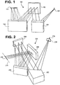
FIG. 2 , amonochromator 200 exemplifying the invention includes aprimary reflector 202, a diffraction grating 204, a firstsecondary reflector 206, a secondsecondary reflector 208, and a photosensitive detector 210 (preferably an array detector including a series of photosensitive elements situated along a focal plane 214). Theprimary reflector 202 is aligned to receive input light (preferably from aninput aperture 212 formed as a slit or hole) and reflect the input light in collimated form to the diffraction grating 204. Thegrating 204 reflects the different component wavelengths of the collimated input light at different respective angles (with three different wavelengths again being depicted by dashed lines having different dash densities). The component wavelengths are then received by a firstsecondary reflector 206 and reflected to a secondsecondary reflector 208, which in turn receives the component wavelengths and reflects them onto different respective regions of thedetector 210, with each of thesecondary reflectors detector 210. - The
primary reflector 202 is preferably an off-axis parabolic mirror, i.e., a section of a parabolic mirror oriented to receive the input light from a direction off the axis of the parabola, since such a mirror can provide effectively ideal collimation of the input light from theaperture 212, with no or minimal aberration. Thus, whereas prior arrangements using spherical mirrors and similar elements introduced aberrations which were then anamorphically magnified by the diffraction grating, here the collimated input light enters and exits the diffraction grating 204 with no or little aberration. Thesecondary reflectors detector 210, and (2) have the secondsecondary reflector 208 provide corrections to the component wavelengths which at least substantially cancel any aberrations introduced by the firstsecondary reflector 206. Thedetector 210 is then situated along afocal plane 214 which is oriented to accommodate the focal points of the reflected component wavelengths of the input light. Since the input light is provided to thegrating 204 with no or little aberration (and thus thegrating 204 provides no or little magnification of such aberration), and since thesecondary reflectors focal plane 214, superior wavelength resolution results. - An interesting characteristic of the
monochromator 200 is that the rays of input light and its component wavelengths will cross in the "wavelength plane" (the plane along which the elements are located and wherein the wavelengths of the input light are separated), unless the beams are redirected/folded out of the wavelength plane by the use of additional optical elements (which then increase size and cost, and also potentially introduce further aberration). In particular, the light received by and reflected from the diffraction grating 204 (from theprimary reflector 202 and to the first secondary reflector 206) intersects the paths of the light received by and reflected from the second secondary reflector 208 (from the firstsecondary reflector 206 and to the detector 210). - When a change in the design wavelength is desired, it is preferred that rather than reorienting the grating 204 (and correspondingly reorienting/relocating any of the other optical elements and/or the detector 210), the
grating 204 should simply be replaced with adifferent grating 204 having the desired design wavelength. This could be done by providing thegrating 204 in a frame which allows manual grating removal and replacement, ordifferent gratings 204 could be provided on a motorized track or wheel which can be translated and/or rotated to situate a desiredgrating 204 in place. - A lens 216 (here depicted as a cylindrical lens) may also be provided between the
input aperture 212 and theprimary reflector 202 to reduce astigmatism in the "non-wavelength" plane perpendicular to the plane in which the light wavelengths are separated, i.e., to concentrate the light in the wavelength plane. This allows thedetector 210 to be made with lesser height in planes perpendicular to the wavelength plane (with thedetector 210 inFIG. 2 having low height in a vertical direction), which can be beneficial for space reduction, as well as for reducing detector noise (e.g., by providing lesser area for impingement by cosmic rays, which can generate spurious detector readings). Thelens 216 allows optical elements such as theprimary reflector 202, diffraction grating 204, firstsecondary reflector 206, and secondsecondary reflector 208 to also be provided with lesser vertical height (and thus an overall "thin" configuration for the monochromator 200) if desired. - Further advantages, features, and objects of the invention will be apparent from the following Detailed Description of the invention in conjunction with the associated drawings.
-
-
FIG. 1 is a schematic perspective view of a conventional (Czerny-Turner-type)monochromator 100, wherein aprimary reflector 104 accepts input light from anaperture 108 and reflects collimated light to adiffraction grating 102, and wherein asecondary reflector 106 then focuses the resulting rays (which are reflected from thegrating 102 at different angles in accordance with their wavelengths) onto anarray detector 110, which then measures light intensity at each wavelength. -
FIG. 2 is a schematic perspective view of a monochromator arrangement exemplifying the present invention, wherein a primary reflector accepts input light from an aperture and reflects collimated light to a diffraction grating; a first secondary reflector then receives the diffracted wavelengths and directs them to a second secondary reflector; and the second secondary reflector focuses each of the diffracted wavelengths onto a respective area of an array detector, which measures light intensity at each wavelength. - To expand on the discussion given in the foregoing Summary, following is a detailed description of components and specifications used to construct an exemplary version of the invention.
- The
input aperture 212 was custom fabricated from a glass plate with a metallic coating, with the coating being selectively removed via photolithography to form three apertures 212 (which could then be selectively chosen for use as desired): a 25 x 2000 micrometer rectangular slit, a 100 micrometer circular hole, and a 25 micrometer circular hole. Theinput lens 216 was chosen to be a model CYL13563 cylindrical lens from JML Optical (Rochester, NY), having 25 mm focal length. - The
primary reflector 202 is a diamond-turned off-axis parabolic aluminum mirror with a 240 mm effective focal length, 40 degree included angle between entrance and exit beams, and roughly 62 mm clear aperture, and was custom fabricated by Corning Net Optix (Keene, NH). - The first
secondary reflector 206 is a concave spherical mirror with a 678.79 mm radius of curvature, and is nominally 60 mm in diameter. The secondsecondary reflector 208 is also a concave spherical mirror with a 1013.18 mm radius of curvature, and is also nominally 60 mm in diameter. Bothsecondary reflectors - An
exemplary grating 204 usable in themonochromator 200 is the model 53119BK01-266R from Newport (Rochester, NY), having 900 grooves per millimeter and a blaze wavelength of 0.56 microns. - An
exemplary detector 210 is a Toshiba TCD1201D photodiode array (PDA) chip having a row of 2048 pixels (elements) arrayed along a thefocal plane 214, each element being approximately14 micrometers wide by 200 micrometers tall (i.e., the entire array is approximately 2.87 cm wide by 200 micrometers tall). - The foregoing elements were arranged as follows (the following distances and angles being rounded to the nearest millimeter or degree): 12 mm from the
input aperture 212 to theinput lens 216; 226 mm from theinput lens 216 to theprimary reflector 202; 250 mm from theprimary reflector 202 to the grating 204 (and a 20 degree separation between entrance and exit beams on the grating 204); 180 mm from thegrating 204 to the first secondary reflector 206 (and a 30 degree included angle on the first secondary reflector 206); 134 mm from the firstsecondary reflector 206 to the second secondary reflector 208 (and a 48 degree included angle on the second secondary reflector 208); and 137 mm from the secondsecondary reflector 208 to the detector 210 (with a 14 degree tilt at the detector 210). - It should be understood that the invention may accommodate a wide range of distances, angles, and components other than those noted above, with optical systems design packages such as ZEMAX (Zemax Development Corporation, Bellvue, WA) being useful for testing the compatibility of proposed components, providing acceptable component specifications and layouts if basic design parameters are provided, and/or for optimizing proposed designs.
- It is emphasized that the foregoing discussion merely relates to preferred versions of the invention, and numerous modifications can be made. Following is a brief exemplary list of such modifications.
- Initially, the
monochromator 200 is preferably provided with baffles (not shown for sake of clarity) which extend at least partially about the outer boundaries of the light reflected from each optical element, but which terminate where beams intersect so the baffles do not block the intended transmission of light from one optical element to another. The baffles therefore reduce "stray light," i.e., accidentally scattered light caused by imperfections in the elements (for example, stray light beams unintentionally reflected from theprimary reflector 202 to the first or secondsecondary reflector 204/206 or to thedetector 210, from the grating 204 to the second secondary reflector 26 or to thedetector 210, etc. Since stray light can lead to spurious readings at thedetector 210, the use of baffles or other means of stray light reduction can help increase the resolution of themonochromator 200. - As previously noted, a
lens 216 can receive the light from theinput aperture 212 and help concentrate the input light about a central "wavelength" plane wherein the wavelengths are separated. This adaptation could allow input from aslit input aperture 212 to be provided to an array oflenses 216 in the non-wavelength plane (i.e., arrayed in the vertical direction inFIG. 2 ), and in turn to the optical elements (theprimary reflector 202,diffraction grating 204, firstsecondary reflector 206, and second secondary reflector 208), wherein thediffraction grating 204 is not a single grating but is in fact a series of stacked gratings which are each optimized for different wavelength ranges. A series of stackeddetectors 210 can then receive the output from each grating. The various gratings and detectors would thereby allow detection of a broader range of wavelengths without the need to replace gratings. In this version of the invention, sheet-like baffles would preferably be provided between each element in the grating/detector "stack" so as to prevent crosstalk. - The
focal plane 214 along which thedetector 210 is arrayed need not be a true plane, i.e., it may be a curved surface. Depending on the optical elements chosen for thesecondary reflectors detector 210 could be arrayed along the curve. However, in many instances the curvature is sufficiently small that a linear/planar array detector 210 can be used with minor loss of resolution (owing to some wavelength bands being out of focus on the detector 210).
Claims (10)
- A monochromator (200) comprising:a. a detector (210);b. a primary reflector (202), which is an off-axis parabolic mirror, the primary reflector being aligned so as to reflect input light in collimated form;c. a diffraction grating (204) receiving the collimated input light containing multiple light wavelengths from the primary reflector (202) and reflecting the different light wavelengths of the collimated light from the primary reflector (202) at different respective angles;d. a first secondary reflector (206) receiving and reflecting the different light wavelengths from the diffraction grating (204); ande. a second secondary reflector (208) receiving the different light wavelengths from the first secondary reflector (206) and reflecting the different light wavelengths onto different respective regions of the detector (210).
- The monochromator (200) of claim 1 wherein the diffraction grating (204), first secondary reflector (206), and second secondary reflector (208) are oriented such that the path traveled by the different light wavelengths transmitted between the second secondary reflector (208) and the detector (210) crosses the paths of:a. the collimated input light received by the diffraction grating (204), andb. the different light wavelengths transmitted between the diffraction grating (204) and the first secondary reflector (206).
- The monochromator (200) of claim 1 wherein the paths traveled by light transmitted between the primary reflector (202), diffraction grating (204), first secondary reflector (206), and second secondary reflector (208) all rest within at least substantially the same plane, with the path of the light transmitted between the primary reflector (202) and the diffraction grating (204) intersecting at least one of the paths of:a. the light wavelengths traveling between the diffraction grating (204) and the first secondary reflector (206), andb. the light wavelengths traveling between the first secondary reflector (206) and the second secondary reflector (208).
- The monochromator (200) of claim 1 further comprising an input aperture (212) through which input light is directed to the primary reflector (202).
- The monochromator (200) of claim 1 wherein the detector (210) is defined by an array of photosensitive elements.
- The monochromator (200) of claim 1 wherein at least one of the paths of the light received by or reflected from the diffraction grating (204) intersects at least one of the paths of the light received by or reflected from the second secondary reflector (208).
- The monochromator (200) of claim 1 wherein the first secondary reflector (206) and second secondary reflector (208) are oriented such that the path traveled by the different light wavelengths transmitted therebetween crosses the path of the collimated input light received by the diffraction grating (204).
- The monochromator (200) of claim 5 wherein the path of the reflected component light wavelengths traveling between the grating (204) and the first secondary reflector (206) intersects the path of the reflected component light wavelengths traveling between the second secondary reflector (208) and a focal plane (214) .
- The monochromator (200) of claim 8 wherein the detector (210) is arrayed along the focal plane (214).
- The monochromator of claim 1, wherein at least one of the first secondary reflector (206) and second secondary reflector (208) are chosen from one of:a. a spherical mirror, andb. a toroidal mirror.
Applications Claiming Priority (2)
| Application Number | Priority Date | Filing Date | Title |
|---|---|---|---|
| US11/331,912 US7345760B2 (en) | 2006-01-13 | 2006-01-13 | Grating monochromator/spectrograph |
| PCT/US2007/001042 WO2007084462A2 (en) | 2006-01-13 | 2007-01-12 | Grating monochromator/spectrograph |
Publications (3)
| Publication Number | Publication Date |
|---|---|
| EP1971835A2 EP1971835A2 (en) | 2008-09-24 |
| EP1971835A4 EP1971835A4 (en) | 2012-07-11 |
| EP1971835B1 true EP1971835B1 (en) | 2021-03-10 |
Family
ID=38262864
Family Applications (1)
| Application Number | Title | Priority Date | Filing Date |
|---|---|---|---|
| EP07716642.9A Active EP1971835B1 (en) | 2006-01-13 | 2007-01-12 | Grating monochromator/spectrograph |
Country Status (3)
| Country | Link |
|---|---|
| US (1) | US7345760B2 (en) |
| EP (1) | EP1971835B1 (en) |
| WO (1) | WO2007084462A2 (en) |
Cited By (1)
| Publication number | Priority date | Publication date | Assignee | Title |
|---|---|---|---|---|
| US12436094B2 (en) | 2023-04-28 | 2025-10-07 | Thermo Electron Scientific Instruments Llc | Adjustable optical system for a spectrograph |
Families Citing this family (18)
| Publication number | Priority date | Publication date | Assignee | Title |
|---|---|---|---|---|
| US20090273840A1 (en) | 2008-05-02 | 2009-11-05 | Mclaughlin Sheldon | Wavelength dispersing device |
| TWI404922B (en) * | 2010-02-02 | 2013-08-11 | Chroma Ate Inc | Spectral spectral measurement system |
| US8797529B2 (en) * | 2011-01-25 | 2014-08-05 | Ocean Optics, Inc. | Spectrometer design for aberration correction, simplified manufacture, and compact footprint |
| CN102331300B (en) * | 2011-06-14 | 2013-10-23 | 北京卓立汉光仪器有限公司 | Asymmetric monochromator for improving luminous flux and resolution |
| US8773659B2 (en) | 2012-01-13 | 2014-07-08 | Roper Scientific Inc. | Anastigmatic imaging spectrograph |
| TWI525308B (en) * | 2012-11-16 | 2016-03-11 | 台灣超微光學股份有限公司 | Spectrometer, assembly method and assembly system thereof |
| CN103604749A (en) * | 2013-11-29 | 2014-02-26 | 中国计量科学研究院 | Detector and diffuse transmission ratio measure system |
| CN103852165A (en) * | 2014-01-17 | 2014-06-11 | 中国科学院上海技术物理研究所 | Medium-wave infrared imaging spectrometer with off-axis spherical surface sapphire prism |
| JP6251073B2 (en) * | 2014-02-05 | 2017-12-20 | 浜松ホトニクス株式会社 | Spectrometer and method of manufacturing the spectrometer |
| CN104501953A (en) * | 2014-12-25 | 2015-04-08 | 中国科学院长春光学精密机械与物理研究所 | Staggered folding optical path structure of small-sized grating monochromator with high spectral resolution |
| CN105352707B (en) * | 2015-08-18 | 2017-09-29 | 中国科学院西安光学精密机械研究所 | Chromatic aberration of magnification test equipment and test method for star sensor optical system |
| CN106641813B (en) * | 2015-11-02 | 2018-07-17 | 北京振兴计量测试研究所 | Vacuum ultraviolet light pipe lighting device |
| JP6673674B2 (en) * | 2015-11-12 | 2020-03-25 | 横河電機株式会社 | Spectrometer |
| DE102016225344A1 (en) * | 2016-12-16 | 2018-06-21 | Fraunhofer-Gesellschaft zur Förderung der angewandten Forschung e.V. | System for analyzing electromagnetic radiation and device for producing the same |
| CN112924480B (en) * | 2021-01-27 | 2023-04-07 | 中国科学院上海高等研究院 | Measuring device for synchronous radiation X-ray and asynchronous infrared light combined use |
| JP7730686B2 (en) * | 2021-08-11 | 2025-08-28 | 株式会社ディスコ | light irradiation device |
| CN113702007B (en) * | 2021-09-02 | 2023-09-19 | 孝感华中精密仪器有限公司 | A calibration device for off-axis beam axis difference and its calibration method |
| JP2023085132A (en) * | 2021-12-08 | 2023-06-20 | 株式会社ニコン | Spectrometer |
Family Cites Families (13)
| Publication number | Priority date | Publication date | Assignee | Title |
|---|---|---|---|---|
| US4265510A (en) | 1979-05-16 | 1981-05-05 | Hughes Aircraft Company | Three mirror anastigmatic optical system |
| DE3614639A1 (en) | 1986-04-30 | 1987-11-05 | Messerschmitt Boelkow Blohm | IMAGING SPECTROMETER |
| US4852079A (en) * | 1987-11-23 | 1989-07-25 | Allied-Signal Inc. | Optical spectral analyzer |
| EP0403228B1 (en) | 1989-06-16 | 1995-08-23 | FISONS plc | Optical system for spectral analysis |
| US5026160A (en) | 1989-10-04 | 1991-06-25 | The United States Of America As Represented By The Secretary Of The Navy | Monolithic optical programmable spectrograph (MOPS) |
| US5192981A (en) | 1990-04-30 | 1993-03-09 | Spex Industries, Inc. | Czerny-Turner monochromator |
| US5384656A (en) | 1991-10-16 | 1995-01-24 | Hyperfine, Inc. | Astigmatism corrected gratings for plane grating and spherical mirror spectrographs |
| US5260767A (en) | 1991-12-16 | 1993-11-09 | Hughes Aircraft Company | Compact all-reflective imaging spectrometer |
| US5305082A (en) * | 1992-01-08 | 1994-04-19 | Chromax, Inc. | High spatial resolution imaging spectrograph |
| JP3250426B2 (en) | 1995-09-27 | 2002-01-28 | 安藤電気株式会社 | Optical spectrum measurement device |
| JP3487242B2 (en) | 1999-11-05 | 2004-01-13 | 株式会社島津製作所 | Microchip electrophoresis device |
| US6886953B2 (en) | 2002-03-22 | 2005-05-03 | Raytheon Company | High-resolution, all-reflective imaging spectrometer |
| US6813018B2 (en) * | 2002-11-07 | 2004-11-02 | The Boeing Company | Hyperspectral imager |
-
2006
- 2006-01-13 US US11/331,912 patent/US7345760B2/en not_active Expired - Lifetime
-
2007
- 2007-01-12 EP EP07716642.9A patent/EP1971835B1/en active Active
- 2007-01-12 WO PCT/US2007/001042 patent/WO2007084462A2/en not_active Ceased
Non-Patent Citations (1)
| Title |
|---|
| None * |
Cited By (1)
| Publication number | Priority date | Publication date | Assignee | Title |
|---|---|---|---|---|
| US12436094B2 (en) | 2023-04-28 | 2025-10-07 | Thermo Electron Scientific Instruments Llc | Adjustable optical system for a spectrograph |
Also Published As
| Publication number | Publication date |
|---|---|
| EP1971835A4 (en) | 2012-07-11 |
| US7345760B2 (en) | 2008-03-18 |
| US20070165224A1 (en) | 2007-07-19 |
| EP1971835A2 (en) | 2008-09-24 |
| WO2007084462A3 (en) | 2008-04-03 |
| WO2007084462A2 (en) | 2007-07-26 |
Similar Documents
| Publication | Publication Date | Title |
|---|---|---|
| EP1971835A2 (en) | Grating monochromator/spectrograph | |
| US6100974A (en) | Imaging spectrometer/camera having convex grating | |
| US6744505B1 (en) | Compact imaging spectrometer | |
| US10024716B2 (en) | Field lens corrected three mirror anastigmat spectrograph | |
| JP3450699B2 (en) | Improved concentric spectrograph, method of dispersing light and method of diffracting two light beams | |
| US8520204B2 (en) | Dyson-type imaging spectrometer having improved image quality and low distortion | |
| US4634276A (en) | Slit imaging system using two concave mirrors | |
| US7817274B2 (en) | Compact spectrometer | |
| US7315371B2 (en) | Multi-channel spectrum analyzer | |
| JP2008510964A (en) | Multichannel, multispectral imaging spectrometer | |
| US11169024B2 (en) | Compact freeform echelle spectrometer | |
| US6597452B1 (en) | Compact littrow-type scanning spectrometer | |
| JPH0584451B2 (en) | ||
| US20010048526A1 (en) | Compact spectrometer | |
| US4850706A (en) | Low profile spectral analysis system | |
| JP2009121986A (en) | Spectrometer | |
| WO1996026418A1 (en) | Method and apparatus for providing astigmatism-reduced images with spectroscopic instruments | |
| US10190912B2 (en) | Optical system of a high-resolution imaging spectrograph for deep UV Raman spectroscopy | |
| US6906798B2 (en) | Multi-path monochromator | |
| US20240385460A1 (en) | Holographic grism as dispersive element in raman spectrographs | |
| Reininger | Imaging spectrometer/camera having convex grating | |
| JP3141106B2 (en) | Convergent light incidence type spectrometer using spherical diffraction grating | |
| KR101884118B1 (en) | Spectrometer based on transmission diffraction grating | |
| US20260118173A1 (en) | Miniature spectrometer | |
| Lensen | The Blaauw Spectrograph design |
Legal Events
| Date | Code | Title | Description |
|---|---|---|---|
| PUAI | Public reference made under article 153(3) epc to a published international application that has entered the european phase |
Free format text: ORIGINAL CODE: 0009012 |
|
| 17P | Request for examination filed |
Effective date: 20080708 |
|
| AK | Designated contracting states |
Kind code of ref document: A2 Designated state(s): AT BE BG CH CY CZ DE DK EE ES FI FR GB GR HU IE IS IT LI LT LU LV MC NL PL PT RO SE SI SK TR |
|
| AX | Request for extension of the european patent |
Extension state: AL BA HR MK RS |
|
| A4 | Supplementary search report drawn up and despatched |
Effective date: 20120608 |
|
| RIC1 | Information provided on ipc code assigned before grant |
Ipc: G01J 3/18 20060101AFI20120601BHEP |
|
| DAX | Request for extension of the european patent (deleted) | ||
| STAA | Information on the status of an ep patent application or granted ep patent |
Free format text: STATUS: EXAMINATION IS IN PROGRESS |
|
| 17Q | First examination report despatched |
Effective date: 20191210 |
|
| GRAP | Despatch of communication of intention to grant a patent |
Free format text: ORIGINAL CODE: EPIDOSNIGR1 |
|
| STAA | Information on the status of an ep patent application or granted ep patent |
Free format text: STATUS: GRANT OF PATENT IS INTENDED |
|
| INTG | Intention to grant announced |
Effective date: 20200508 |
|
| GRAJ | Information related to disapproval of communication of intention to grant by the applicant or resumption of examination proceedings by the epo deleted |
Free format text: ORIGINAL CODE: EPIDOSDIGR1 |
|
| STAA | Information on the status of an ep patent application or granted ep patent |
Free format text: STATUS: EXAMINATION IS IN PROGRESS |
|
| INTC | Intention to grant announced (deleted) | ||
| GRAP | Despatch of communication of intention to grant a patent |
Free format text: ORIGINAL CODE: EPIDOSNIGR1 |
|
| STAA | Information on the status of an ep patent application or granted ep patent |
Free format text: STATUS: GRANT OF PATENT IS INTENDED |
|
| INTG | Intention to grant announced |
Effective date: 20200928 |
|
| GRAS | Grant fee paid |
Free format text: ORIGINAL CODE: EPIDOSNIGR3 |
|
| GRAA | (expected) grant |
Free format text: ORIGINAL CODE: 0009210 |
|
| STAA | Information on the status of an ep patent application or granted ep patent |
Free format text: STATUS: THE PATENT HAS BEEN GRANTED |
|
| AK | Designated contracting states |
Kind code of ref document: B1 Designated state(s): AT BE BG CH CY CZ DE DK EE ES FI FR GB GR HU IE IS IT LI LT LU LV MC NL PL PT RO SE SI SK TR |
|
| REG | Reference to a national code |
Ref country code: GB Ref legal event code: FG4D |
|
| REG | Reference to a national code |
Ref country code: AT Ref legal event code: REF Ref document number: 1370337 Country of ref document: AT Kind code of ref document: T Effective date: 20210315 Ref country code: CH Ref legal event code: EP |
|
| REG | Reference to a national code |
Ref country code: IE Ref legal event code: FG4D |
|
| REG | Reference to a national code |
Ref country code: DE Ref legal event code: R096 Ref document number: 602007060979 Country of ref document: DE |
|
| REG | Reference to a national code |
Ref country code: LT Ref legal event code: MG9D |
|
| PG25 | Lapsed in a contracting state [announced via postgrant information from national office to epo] |
Ref country code: LT Free format text: LAPSE BECAUSE OF FAILURE TO SUBMIT A TRANSLATION OF THE DESCRIPTION OR TO PAY THE FEE WITHIN THE PRESCRIBED TIME-LIMIT Effective date: 20210310 Ref country code: GR Free format text: LAPSE BECAUSE OF FAILURE TO SUBMIT A TRANSLATION OF THE DESCRIPTION OR TO PAY THE FEE WITHIN THE PRESCRIBED TIME-LIMIT Effective date: 20210611 Ref country code: FI Free format text: LAPSE BECAUSE OF FAILURE TO SUBMIT A TRANSLATION OF THE DESCRIPTION OR TO PAY THE FEE WITHIN THE PRESCRIBED TIME-LIMIT Effective date: 20210310 Ref country code: BG Free format text: LAPSE BECAUSE OF FAILURE TO SUBMIT A TRANSLATION OF THE DESCRIPTION OR TO PAY THE FEE WITHIN THE PRESCRIBED TIME-LIMIT Effective date: 20210610 |
|
| REG | Reference to a national code |
Ref country code: AT Ref legal event code: MK05 Ref document number: 1370337 Country of ref document: AT Kind code of ref document: T Effective date: 20210310 |
|
| REG | Reference to a national code |
Ref country code: NL Ref legal event code: MP Effective date: 20210310 |
|
| PG25 | Lapsed in a contracting state [announced via postgrant information from national office to epo] |
Ref country code: SE Free format text: LAPSE BECAUSE OF FAILURE TO SUBMIT A TRANSLATION OF THE DESCRIPTION OR TO PAY THE FEE WITHIN THE PRESCRIBED TIME-LIMIT Effective date: 20210310 Ref country code: LV Free format text: LAPSE BECAUSE OF FAILURE TO SUBMIT A TRANSLATION OF THE DESCRIPTION OR TO PAY THE FEE WITHIN THE PRESCRIBED TIME-LIMIT Effective date: 20210310 |
|
| PG25 | Lapsed in a contracting state [announced via postgrant information from national office to epo] |
Ref country code: NL Free format text: LAPSE BECAUSE OF FAILURE TO SUBMIT A TRANSLATION OF THE DESCRIPTION OR TO PAY THE FEE WITHIN THE PRESCRIBED TIME-LIMIT Effective date: 20210310 |
|
| PG25 | Lapsed in a contracting state [announced via postgrant information from national office to epo] |
Ref country code: AT Free format text: LAPSE BECAUSE OF FAILURE TO SUBMIT A TRANSLATION OF THE DESCRIPTION OR TO PAY THE FEE WITHIN THE PRESCRIBED TIME-LIMIT Effective date: 20210310 Ref country code: CZ Free format text: LAPSE BECAUSE OF FAILURE TO SUBMIT A TRANSLATION OF THE DESCRIPTION OR TO PAY THE FEE WITHIN THE PRESCRIBED TIME-LIMIT Effective date: 20210310 Ref country code: EE Free format text: LAPSE BECAUSE OF FAILURE TO SUBMIT A TRANSLATION OF THE DESCRIPTION OR TO PAY THE FEE WITHIN THE PRESCRIBED TIME-LIMIT Effective date: 20210310 |
|
| PG25 | Lapsed in a contracting state [announced via postgrant information from national office to epo] |
Ref country code: RO Free format text: LAPSE BECAUSE OF FAILURE TO SUBMIT A TRANSLATION OF THE DESCRIPTION OR TO PAY THE FEE WITHIN THE PRESCRIBED TIME-LIMIT Effective date: 20210310 Ref country code: IS Free format text: LAPSE BECAUSE OF FAILURE TO SUBMIT A TRANSLATION OF THE DESCRIPTION OR TO PAY THE FEE WITHIN THE PRESCRIBED TIME-LIMIT Effective date: 20210710 Ref country code: PL Free format text: LAPSE BECAUSE OF FAILURE TO SUBMIT A TRANSLATION OF THE DESCRIPTION OR TO PAY THE FEE WITHIN THE PRESCRIBED TIME-LIMIT Effective date: 20210310 Ref country code: PT Free format text: LAPSE BECAUSE OF FAILURE TO SUBMIT A TRANSLATION OF THE DESCRIPTION OR TO PAY THE FEE WITHIN THE PRESCRIBED TIME-LIMIT Effective date: 20210712 Ref country code: SK Free format text: LAPSE BECAUSE OF FAILURE TO SUBMIT A TRANSLATION OF THE DESCRIPTION OR TO PAY THE FEE WITHIN THE PRESCRIBED TIME-LIMIT Effective date: 20210310 Ref country code: ES Free format text: LAPSE BECAUSE OF FAILURE TO SUBMIT A TRANSLATION OF THE DESCRIPTION OR TO PAY THE FEE WITHIN THE PRESCRIBED TIME-LIMIT Effective date: 20210310 |
|
| REG | Reference to a national code |
Ref country code: DE Ref legal event code: R097 Ref document number: 602007060979 Country of ref document: DE |
|
| PLBE | No opposition filed within time limit |
Free format text: ORIGINAL CODE: 0009261 |
|
| STAA | Information on the status of an ep patent application or granted ep patent |
Free format text: STATUS: NO OPPOSITION FILED WITHIN TIME LIMIT |
|
| PG25 | Lapsed in a contracting state [announced via postgrant information from national office to epo] |
Ref country code: DK Free format text: LAPSE BECAUSE OF FAILURE TO SUBMIT A TRANSLATION OF THE DESCRIPTION OR TO PAY THE FEE WITHIN THE PRESCRIBED TIME-LIMIT Effective date: 20210310 |
|
| 26N | No opposition filed |
Effective date: 20211213 |
|
| PG25 | Lapsed in a contracting state [announced via postgrant information from national office to epo] |
Ref country code: SI Free format text: LAPSE BECAUSE OF FAILURE TO SUBMIT A TRANSLATION OF THE DESCRIPTION OR TO PAY THE FEE WITHIN THE PRESCRIBED TIME-LIMIT Effective date: 20210310 |
|
| PG25 | Lapsed in a contracting state [announced via postgrant information from national office to epo] |
Ref country code: IT Free format text: LAPSE BECAUSE OF FAILURE TO SUBMIT A TRANSLATION OF THE DESCRIPTION OR TO PAY THE FEE WITHIN THE PRESCRIBED TIME-LIMIT Effective date: 20210310 |
|
| PG25 | Lapsed in a contracting state [announced via postgrant information from national office to epo] |
Ref country code: IS Free format text: LAPSE BECAUSE OF FAILURE TO SUBMIT A TRANSLATION OF THE DESCRIPTION OR TO PAY THE FEE WITHIN THE PRESCRIBED TIME-LIMIT Effective date: 20210710 |
|
| PG25 | Lapsed in a contracting state [announced via postgrant information from national office to epo] |
Ref country code: MC Free format text: LAPSE BECAUSE OF FAILURE TO SUBMIT A TRANSLATION OF THE DESCRIPTION OR TO PAY THE FEE WITHIN THE PRESCRIBED TIME-LIMIT Effective date: 20210310 |
|
| REG | Reference to a national code |
Ref country code: CH Ref legal event code: PL |
|
| REG | Reference to a national code |
Ref country code: BE Ref legal event code: MM Effective date: 20220131 |
|
| PG25 | Lapsed in a contracting state [announced via postgrant information from national office to epo] |
Ref country code: LU Free format text: LAPSE BECAUSE OF NON-PAYMENT OF DUE FEES Effective date: 20220112 |
|
| PG25 | Lapsed in a contracting state [announced via postgrant information from national office to epo] |
Ref country code: BE Free format text: LAPSE BECAUSE OF NON-PAYMENT OF DUE FEES Effective date: 20220131 |
|
| PG25 | Lapsed in a contracting state [announced via postgrant information from national office to epo] |
Ref country code: LI Free format text: LAPSE BECAUSE OF NON-PAYMENT OF DUE FEES Effective date: 20220131 Ref country code: CH Free format text: LAPSE BECAUSE OF NON-PAYMENT OF DUE FEES Effective date: 20220131 |
|
| PG25 | Lapsed in a contracting state [announced via postgrant information from national office to epo] |
Ref country code: IE Free format text: LAPSE BECAUSE OF NON-PAYMENT OF DUE FEES Effective date: 20220112 |
|
| PG25 | Lapsed in a contracting state [announced via postgrant information from national office to epo] |
Ref country code: HU Free format text: LAPSE BECAUSE OF FAILURE TO SUBMIT A TRANSLATION OF THE DESCRIPTION OR TO PAY THE FEE WITHIN THE PRESCRIBED TIME-LIMIT; INVALID AB INITIO Effective date: 20070112 |
|
| PG25 | Lapsed in a contracting state [announced via postgrant information from national office to epo] |
Ref country code: CY Free format text: LAPSE BECAUSE OF FAILURE TO SUBMIT A TRANSLATION OF THE DESCRIPTION OR TO PAY THE FEE WITHIN THE PRESCRIBED TIME-LIMIT Effective date: 20210310 |
|
| PGFP | Annual fee paid to national office [announced via postgrant information from national office to epo] |
Ref country code: GB Payment date: 20260108 Year of fee payment: 20 |
|
| PGFP | Annual fee paid to national office [announced via postgrant information from national office to epo] |
Ref country code: DE Payment date: 20251211 Year of fee payment: 20 |
|
| PGFP | Annual fee paid to national office [announced via postgrant information from national office to epo] |
Ref country code: FR Payment date: 20260112 Year of fee payment: 20 |