EP1970973A1 - Verfahren zur thermischen Abstimmung eines thermoelektrischen Generators auf eine Wärmequelle mit hohem Wärmewiderstand und so erhaltener thermoelektrischer Generator - Google Patents
Verfahren zur thermischen Abstimmung eines thermoelektrischen Generators auf eine Wärmequelle mit hohem Wärmewiderstand und so erhaltener thermoelektrischer Generator Download PDFInfo
- Publication number
- EP1970973A1 EP1970973A1 EP07447010A EP07447010A EP1970973A1 EP 1970973 A1 EP1970973 A1 EP 1970973A1 EP 07447010 A EP07447010 A EP 07447010A EP 07447010 A EP07447010 A EP 07447010A EP 1970973 A1 EP1970973 A1 EP 1970973A1
- Authority
- EP
- European Patent Office
- Prior art keywords
- thermoelectric generator
- thermopile
- thermal resistance
- stage
- teg
- Prior art date
- Legal status (The legal status is an assumption and is not a legal conclusion. Google has not performed a legal analysis and makes no representation as to the accuracy of the status listed.)
- Granted
Links
Images


Classifications
-
- H—ELECTRICITY
- H10—SEMICONDUCTOR DEVICES; ELECTRIC SOLID-STATE DEVICES NOT OTHERWISE PROVIDED FOR
- H10N—ELECTRIC SOLID-STATE DEVICES NOT OTHERWISE PROVIDED FOR
- H10N10/00—Thermoelectric devices comprising a junction of dissimilar materials, i.e. devices exhibiting Seebeck or Peltier effects
- H10N10/10—Thermoelectric devices comprising a junction of dissimilar materials, i.e. devices exhibiting Seebeck or Peltier effects operating with only the Peltier or Seebeck effects
- H10N10/13—Thermoelectric devices comprising a junction of dissimilar materials, i.e. devices exhibiting Seebeck or Peltier effects operating with only the Peltier or Seebeck effects characterised by the heat-exchanging means at the junction
Definitions
- the present invention relates to thermoelectric generators (TEGs) and more specifically to TEGs operated with a heat source having a high thermal resistance, more specifically to TEGs operated under conditions of non-constant heat flow and non-constant temperature difference between hot and cold plates. More specifically, embodiments of this invention relate to a method for thermal matching of a TEG with a heat source and a heat sink in case the TEG is used on an object with high thermal resistance, e.g. on a human body or on a body of any other homeotherm, and dissipates heat into a fluid such as air.
- TEGs thermoelectric generators
- embodiments of this invention relate to a method for thermal matching of a TEG with a heat source an a heat sink in case the TEG receives heat from a fluid, like for example air, having a different temperature with respect to an object with high thermal resistance, e.g. a human body or a body of any other homeotherm, onto which the TEG is positioned. Furthermore this invention relates to TEGs designed according to this thermal matching method.
- thermoelectric generator utilises a temperature difference occurring between a hot (warm) object, i.e. a heat source, and its colder surrounding, i.e. a heat sink, and is used to transform a consequent heat flow into a useful electrical power.
- the necessary heat can for example be produced by radioactive materials, as e.g. in space applications, or by sources available in the ambient, like e.g. standard cooling/heating systems, pipe lines including pipe lines with warm waste water, surfaces of engines, parts of machines and buildings or by homeotherms (i.e. by warm-blooded animals or human beings).
- Natural temperature gradients could be used as well as geothermal temperature gradients, temperature gradients on ambient objects when naturally cooling/heating at night/day, temperature differences between a liquid or a gas in a pipeline and its surrounding, heated machinery, engines, transport and ambient air, between window glass and air indoor or outdoor, etc.
- TEGs mounted in a wristwatch have been used to generate electricity from wasted human heat, thus providing a power source for the watch itself, see M. Kishi, H. Nemoto, T. Hamao, M. Yamamoto, S. Sudou, M. Mandai and S. Yamamoto in "Micro-Thermoelectric Modules and Their Application to Wristwatches as an Energy Source", Proceedings ICT'99 18th Int. Conference on Thermoelectrics, p.301-307, 1999 (Seiko Instruments).
- thermopiles specially suited for such applications are reported by V. Leonov, P. Fiorini, S. Sedky, T. Torfs and C. Van Hoof in "Thermoelectric MEMS generators as a power supply for a body area network", Proceedings of the 13th International Conference on Solid-State Sensors, Actuators and Microsystems (Transducers'05), 2005, pp.291-294 .
- TEGs can be characterised by an electrical and a thermal resistance and by both voltage and power generated per unit temperature difference between the hot and cold sides of the TEG. The relative importance of these factors depends on the specific application. In general, electrical resistance should be low and, obviously, voltage or power output should be maximised (in particular in applications with small temperature difference, i.e. a few degrees C or a few tens degrees C). If a constant temperature difference is imposed at the boundaries of the TEG, e.g. by means of hot and cold plates at fixed temperatures relative to each other, the value of thermal resistance is not crucial, because the output voltage and the output power are proportional to the temperature difference, which is fixed.
- the thermal resistance on one hand, has to be large enough to generate a reasonable temperature drop over the device, but on the other hand, has to be small enough to avoid a drastical decrease in the heat flow through the TEG, for example by more than a factor of 2.
- Constant heat flow means that in the considered range of TEG thermal resistances the heat flow through the device is constant (limited by the ambient). However, this does not mean that the heat flow stays at the same value over time in a practical application.
- the term “limited heat flow” means that when decreasing the thermal resistance of the TEG, the heat flow through the device increases till a certain value, at which the conditions of constant heat flow are reached. In the case of "limited heat flow” the heat flow through the device is not limited by the ambient, but for example by the thermal resistance of the TEG.
- thermocouple 10 The basic element of a TEG is a thermocouple 10 ( Fig. 1 ).
- An example of a thermocouple 10 for use with the present invention comprises a first leg 11 and a second leg 12 formed of two different thermoelectric materials, for example of the same but oppositely doped semiconductor material and exhibiting low thermal conductance and low electrical resistance.
- the legs 11, 12 could be formed from BiTe. If the first leg 11 is formed of n-type BiTe, then the second leg 12 may be formed of p-type BiTe, and vice versa.
- the legs 11, 12 are connected by an electrically conductive interconnect, e.g. a metal layer interconnect 13, which fonns a low-resistance ohmic contact to the semiconductor legs 11, 12, thus forming a junction between the semiconductor legs 11,12.
- thermopile 21 comprising a plurality, preferably a large number, of thermocouples 10, is shown, wherein the junctions between legs 11, 12 are located in two planes: a hot junction plane 24 and a cold junction plane 25.
- the thermopile 21 is sandwiched in between a hot plate 22 and a cold plate 23.
- the hot plate 22 and the cold plate 23 are made of materials having a large thermal conductivity, so that the thermal conductance of the plates 22, 23 is much larger (at least a factor of 10) than the total thermal conductance of the thermopile 21.
- the output voltage and power depend on the number of thermocouples 10 comprised in it. It can easily be shown that in the case of constant heat flow, the maximum power is obtained when the heat flow through the thermoelectric material is equal to the "parasitic" heat exchange between the hot plate 22 and the cold plate 23 through the air; including radiation heat exchange.
- the TEG device area may be fixed to 1 cm 2 and the heat flow is limited by a value of 18.5 mW/cm 2 , which is about 3 times larger than the natural heat flow from human beings to the environment at indoor conditions.
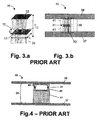
- Such heat flow is obtainable using the design of the TEG 40 according to EP 1 612 870 , as depicted in Figs. 3 to 6 , with a micromachined thermopile 31 between a hot die 45 featured with a pillar/rim structure and a cold die 46, provided with a spacer 41 to increase the distance 39 in between the two plates 37, 38.
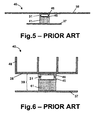
- the hot and cold plates 37, 38 may be provided for the hot and cold plates 37, 38: using a large hot plate 37 and a large cold plate 38 ( Fig. 4 ), or using a smaller hot plate 37 and a larger cold plate 38 ( Fig. 5 ).
- the cold plate 38 can also be folded or shaped as a radiator 48 of more complex shapes, e.g. as shown in Fig.6 for a multi-fin radiator case.
- the legs 11, 12 of the thermocouples 10 are made of respectively n- and p-type BiTe, and that the TEG 20 operates in air.
- the thermal resistance of the metal layer interconnect 13 and the electrical resistance of the contacts between the legs 11, 12 of the thermocouple 10 and the metal layer interconnect 13 are considered to be negligible.
- a commercial TEG 20 is considered. Dimensions chosen for the legs 11, 12 are close to those of the best commercial devices, i.e. a lateral size a of 0.25 mm, the lateral size a being defined as the square root of the cross-section of the legs, and a height h of 0.75 mm ( Fig. 1 ).
- the output power P out (solid line) and output voltage V out (dashed line) for such a TEG 20 are illustrated as a function of the number of thermocouples 10.
- the output voltage is low, i.e. 15 mV as can be seen from Fig. 7 , which is well below the level necessary for powering standard electronics. Typical voltages needed are 3 to 5 V. It is easy and efficient and known to a person skilled in the art to up-convcrt for example 800 mV to these values, however, it is much more difficult and less efficient to reach these values starting from 300 mV or lower.
- the temperature drop corresponding to the maximum power is about 2.3 K.
- the performance of the TEG 20 can be improved by increasing the aspect ratio of the legs 11, 12.
- the lateral size a and height h of the legs 11, 12 are respectively 0.08 mm and 0.6 mm.
- a 0.4 cm 2 TEG (10 units of 2 ⁇ 2 mm 2 size each arc used in the watch described) gives a voltage of 0.15 V when it delivers a maximum power of about 0.022 mW on a load.
- a micromachined TEG 20 which comprises legs with a thickness of 0.5 ⁇ m, a width of 1 ⁇ m and a height of 5 ⁇ m.
- the output power (o) and voltage ( ⁇ ) are shown as a function of the number of thermocouples 10. The power is limited to only 0.00011 mW. This maximal power is achieved for a TEG 20 comprising about 1.8 million thermocouples 10 (see Fig. 9 ). For the same number of thermocouples 10, a voltage of about 3V is obtained.
- the temperature difference (o) between the hot and the cold plates (22, 23) and the electrical resistance ( ⁇ ) of a micromachined TEG 20 are reported.
- the temperature difference (o) between the hot and the cold plates of the TEG 20 at the maximal power is limited to 18 mK.
- the above results are confirmed by experimental data. For example, as described by Infineon ( M. Strasser, R. Aigner, C. Lauterbach, T. Sturm, M. Franosch and G.
- thermocouples 10 have been fabricated and a large output voltage is obtained.
- micromachined TEGs produced by Infineon show about 10 mK temperature difference between the hot and the cold side ( H. Böttner in "Thermoelectric Micro Devices: Current State, Recent Developments and future Aspects for Technological Progress and Applications", Proceedings of the 21st International Conference on Thermoelectrics, p.511-518, 2002 ).
- thermocouples 10 For the number of thermocouples 10 at which the maximum power is achieved (see Fig. 9 ), the electrical resistance approaches 0.4 G ⁇ (see Fig. 10 ), which is a too high value to be efficient e.g. for a generator powering electronic devices or battery chargers. It can be seen that the optimal number of thermocouples 10 is about 1.8 million, because in that case the thermal resistance of the air between the hot plate 22 and the cold plate 23 of the thermopile 21 is equal to the thermal resistance of the thermoelectric material forming the thermocouples 10, so the output power is maximized.
- a TEG device with an area of 1 cm 2 and with this large number of thermocouples 10 can be fabricated if one thermocouple 10 occupies a square of only about 7x7 ⁇ m 2 size.
- thermocouples 10 furthermore has the drawback of increased probability of getting a non-functioning device, since thermocouples 10 are electrically coupled in series. Hence, the failure of one thermocouple 10 will cause the failure of the whole TEG 20. This drawback potentially leads to a dramatically decreased yield of good devices and increased cost of manufacturing.
- P out 1 16 ⁇ S 2 ⁇ W u 2 ⁇ A 2 g ic ⁇ ⁇ ⁇ 1
- G air 1 16 ⁇ S 2 ⁇ W u 2 ⁇ A g ic ⁇ ⁇ h g a
- V out W u ⁇ AS h 2 ⁇ g u ⁇ a 2 ,
- Equation (1) and (2) show that, at the maximum power condition the number n of necessary thermocouples and the output voltage depend on the ratio hla 2 . It can then be stated that micromachined thermoelectric generators require a larger number of thermocouples and deliver power at a larger voltage than non-micromachined generators.
- the power P out and temperature difference ⁇ T depend mainly on the thermal conductance G air of the air between the hot plate and the cold plate. Since this thermal conductance G air is large for micromachined thermopiles, the temperature drop ⁇ T and power P out are low for these devices.
- n G air g a ⁇ b 2 + g ic ⁇ a 2 h ]
- b is the lateral size of the plates 32, 33 corresponding to a basic element 30, as indicated in Fig. 3 .
- thermocouples 10 and expression (6) for the power are similar to expressions (1) and (2), however, according to EP 1 612 870 , G air is small. As a consequence, the number of thermocouples 10 to obtain the maximal power is reduced, while the maximal power is increased.
- the expression (7) of the voltage is also similar to expression (4), it mainly depends on the dimensions of the thermocouples 10.
- the prior art method of optimizing is in finding a condition of equality of the thermal conductance through the air to the thermal conductance through the thermopile leg material, giving the optimal number of thermocouples corresponding to the maximal power generated.
- the output power is plotted in Fig.
- thermocouples 10 versus the ratio of the thermal resistance of the thermopile leg material to the parasitic thermal resistance of the air (each ratio corresponding to a different number of thermocouples) and is found to obey equations (1)-(4). Calculations are performed for a 1 x 1 cm 2 chip size, i.e. larger than used in Seiko thermopiles, in order to reach matching conditions, i.e. when the thermal resistance of the thermopile is equal to the thermal resistance of the air in between the two plates.
- the optimal number of thermocouples 10 is found for the following conditions: the source temperature T s inside the human body, i.e.
- the core temperature is 37 °C
- the environmental temperature of ambient air, T amb is 22 °C
- the thermal resistance of the body R th 300 cm 2 .K/W
- the contact area of the device with the skin is 1 cm 2
- the distance between the hot and the cold plates is 0.6 mm.
- the material parameters used for the modelling are reported in Table I.
- the material parameters used for the modelling are reported in Table I hereinabove.
- thermocouples Optimising a micromachined TEG 40 ( Figs. 3 to 6 ) fabricated according to EP 1 612 870 when the thermopiles are being positioned on a spacer 41, is performed next. According to the state of the art, the matching conditions can be found using equations (5)-(7). The optimal number of thermocouples is then considered to occur at the same conditions as in above two examples, i.e. when the thermal conductance through the air in between the hot and cold plates is equal to the thermal conductance through the thermopile leg material. However, when the results are plotted, see Fig.
- the plot shows a distinct mismatch of the optimal power to the condition of the equality of the thermal conductance through the air to the thermal conductance through the thermopile leg material, and true matching conditions must be found to make the TEG generate the maximal power. It is pointed out that the thermal resistance of the heat source and the heat sink as seen in equations (1)-(7), does not affect the result of the TEG 20 and TEG 40 optimisation according to the prior art.
- the ratio of thermal resistance R th,tp between the hot and cold junctions of the thermopile to the thermal resistance R th, source-sink between the heat source and the heat sink is an important property of the thermal design of a TEG for application on a heat source with large thermal resistance. This is of lesser importance when the thermopile is used under condition of a constant temperature difference between the hot plate and the cold plate. However, this becomes important in case of constant or limited heat flow especially in case of application of the TEG on a heat source with large thermal resistance when the heat flow is varied depending on the thermal resistance of the thermopile.
- This ratio is equal to the coefficient of utilization of the temperature difference, C T , occurring between the heat source and the sink.
- T amb is the temperature of ambient air in case it is used as a heat sink or, e.g., a radiant temperature of ambient space if the TEG is used for space applications.
- thermoelectric generators TEGs
- the present invention provides a method for thermal matching of such a TEG with its heat source and its heat sink.
- thermoelectric generator for connection between a heat source and a heat sink comprises a thermopile unit, the thermopile unit comprising at least one thermopile stage, each thermopile stage comprising a number of thermocouples each having a couple of thermocouple legs, the thermocouple legs being provided in between a hot junction plane and a cold junction plane.
- thermocouples in a thermoelectric generator is such that the thermal resistance (R TEG ) of the thermoelectric generator between the hot junction plane comprising the hottest junctions of a thermopile stage and the cold junction plane comprising the coldest junctions of the thermopile stage does not deviate more than 50%, preferably not more than 20%, more preferred not more than 10%, still more preferred not more than 5% from the thermal resistance of the ambient (R th,amb ), being the sum of the thermal resistance of the heat source, the thermal resistance of the heat sink and the thermal resistance of all parts of the thermoelectric generator serially coupled to the at least one thermopile stage, multiplied by the parasitic thermal resistance (R TEG,0,1 ) between the hot junction plane comprising the hottest junctions of the thermopile stage and the cold junction plane comprising the coldest junctions of the thermopile stage for a same thermoelectric generator but comprising no thermocouples or only one thermocouple leg, this product being divided by the sum of the parasitic thermal resistance
- At least one of the at least one thermopile stage may comprise a first plate thermally connected to the junctions in the hot junction plane and/or a second plate thermally connected to the junctions in the cold junction plane.
- the thermopile unit may be thermally connected to and positioned in between a hot plate for connection to the heat source and a cold plate for connection to the heat sink.
- the thermoelectric generator may furthermore comprise a radiator mounted on or placed instead of the cold plate.
- the surface area of the hot plate may be larger than the area of the thermopile unit, the area of the thermopile unit being determined in a plane parallel to the hot plate, and/or the surface area of the cold plate may be larger than the area of the thermopile unit, the area of the thermopile unit being determined in a plane parallel to the cold plate, so as to obtain a better thermal matching.
- the area of the thermopile unit may be determined by a perpendicular projection of the thermopile unit onto the hot or cold plate.
- the thermoelectric generator according to embodiments of the present invention may further comprise at least one thermally conductive spacer between the at least one thermopile stage and the hot plate and/or the cold plate and/or the radiator and/or between two of the thermopile stages.
- thermopile unit may comprise more than one thermopile stage, thus improving the Rayleigh number or Reynolds number of the heat transfer at the surface of the cold plate or at the surface of the radiator as compared with the same thermoelectric generator comprising a thermopile unit with one thermopile stage.
- the thermoelectric generator may furthermore comprise at least one heat-spreading chip between the at least one thermopile stage and the hot plate and/or the cold plate and/or between two of said at least one thermopile stages.
- a radiator may be mounted on or placed instead of the cold plate.
- the thermoelectric generator according to embodiments of the present invention may furthermore comprise a shock-protecting structure.
- the shock-protecting structure may for example comprise a thermally isolating plate with pillars from thermally isolating material connected to the cold plate.
- the thermoelectric generator according to embodiments of the present invention may furthermore comprise a touch-protecting structure.
- thermoelectric generator may furthermore comprise a thermal reflector positioned in between the hot plate and the cold plate, the thermal reflector covering the hot plate, the cold plate, the radiator, the first plate and/or the second plate and being thermally isolated therefrom.
- the thermoelectric generator according to embodiments of the present invention may be attached to a wrist strap, a head strap, a strap for animals or may be embedded into clothes and garments, a cap, a shoe, a belt, jewellery or a clamp for attaching to such objects.
- the thermoelectric generator may be supplied with additional heat transfer means mounted in a piece of clothing for being worn above or under garment in which said thermoelectric generator is embedded or attached. These heat transfer means may include heat-conductive threads or wires into the piece of clothing.
- thermocouples may be micromachined thermocouples.
- the thermocouples may be positioned on a polymer tape or on a membrane, or thin/thick-film thermocouples without a substrate may be used.
- At least one of the at least one thermopile stage may comprise a thermally conductive structure forming a thermal interconnection between the thennocouple legs and at least one of the cold plate, the hot plate, and the radiator, said thermally conductive structure comprising a thin/thick film of thermally conductive material or a substrate material.
- the thermoelectric generator may be filled at least partially with thermally isolating material.
- This thermally isolating material may for example be a micro- or sub-microporous material having a thermal conductivity less than the thermal conductivity of air or not exceeding the thermal conductivity of air by 50%.
- the inner volume of the thermoelectric generator according to embodiments of the present invention may be encapsulated on its perimeter between the hot plate and the cold plate or the radiator, using a layer of thermally isolating material. This layer of thermally isolating material may also serve as a shock-protecting structure.
- the volume between the hot plate and the cold plate or the radiator may be filled with a gas having lower thermal conductivity than air or which is at a pressure that is lower than the atmospheric pressure.
- the inner surface of the hot plate or the inner surface of the reflector may have a low emissivity (lower than 20%, preferably lower than 10%) in the infrared region and the inner surface of the cold plate and the radiator (the inner surface being the surface not facing the heat sink) may have a high emissivity (higher than 90%, preferably higher than 95%) in the infrared region.
- the present invention is furthermore related to a method for designing a thermoelectric generator for connection between a heat source and a heat sink and with a limited heat flow through the thermoelectric generator and a non-constant temperature difference between the heat source and the heat sink, the thermoelectric generator comprising a thermopile unit, said thermopile unit comprising at least one thermopile stage, each thermopile stage comprising a number of thermocouples each having a couple of thermocouple legs, the thermocouple legs being provided in between a hot junction plane and a cold junction plane.
- the design method comprises: determining the thermal resistance (R TEG ) of the thermoelectric generator between the hot junction plane comprising the hottest junctions of the thermopile stage and the cold junction plane comprising the coldest junctions of the thermopile stage as a function of the number of thernmocouples; determining the sum (R th,amb ) of the thermal resistance of the heat source, the thermal resistance of the heat sink and the thermal resistance of all parts of the thermoelectric generator serially coupled to the at least one thermopile stage, as a function of the number of thermocouples; determining the parasitic thermal resistance (R TEG,0,1 ) between the hot junction plane comprising the hottest junctions of the thermopile stage and the cold junction plane comprising the coldest junctions of the thermopile stage for a same thermoelectric generator but comprising no thermocouples or only one thermocouple leg; determining the sum (R th,0,1,amb )of the thermal resistance of the heat source, the thermal resistance of the heat sink and the thermal resistance of all parts of
- limited heat flow means that when decreasing the thermal resistance of the TEG, the heat flow through the device increases till a certain value, at which the conditions of constant heat flow are reached. In the case of “limited heat flow” the heat flow through the device is not limited by the ambient, but for example by the thermal resistance of the TEG or by the thermal resistance of the heat sink.
- Embodiments of the method for designing a thermoelectric generator may furthermore comprise varying the shape and/or the size of a hot plate and/or a cold plate and/or a radiator, whereby the thermopile unit is thermally connected to and positioned in between the hot plate for connection to the heat source and the cold plate for connection to the heat sink
- the method for designing a thermoelectric generator according to embodiments of the present invention may furthermore comprise providing at least one thermally conductive spacer in between the at least one thermopile stage and the hot plate and/or the cold plate and/or the radiator and/or between two of the thermopile stages.
- the at least one thermally conductive spacer may improve the Rayleigh number or Reynolds number of the heat transfer at the surface of the cold plate or at the surface of the radiator as compared with the same thermoelectric generator without said at least one thermally conductive spacer.
- the method for designing a thermoelectric generator may furthermore comprise providing a radiator mounted on or placed instead of the cold plate, and varying the size and/or the shape of the radiator.
- the thermocouples may be positioned on a polymer tape or on a membrane, or thin/thick-film thermocouples without a substrate may be used.
- the present invention provides a computer program product for executing a method for designing a thermoelectric generator according to embodiments of the present invention.
- the present invention also provides a machine readable data storage device storing the computer program product in accordance with embodiments of the present invention.
- the present invention also provides transmission of the computer program product in accordance with embodiments of the present invention over a local or wide area telecommunications network.
- the thermoelectric generator according to embodiments of the present invention may be used with an animal, a human being, a clothed human being or ambient air as a heat source and with ambient air, an animal, a human being or a clothed human being as a heat sink.
- the thermoelectric generator according to embodiments of the present invention may be used with a space object or an artificial space object as a heat source and interplanetary space, a space object or an artificial space object as a heat sink.
- the thermoelectric generator may be used with a distant radiating object or a plurality of distant radiating objects like space objects or ambient objects as a heat source and Earth surface as a heat sink.
- the TEG 49 as illustrated in Fig. 14 comprises a thermopile unit 50, comprising a thermopile 21 which in its simplest shape is formed by a certain, pre-determined, number of thermocouples 10 electrically connected in series, and placed in between plates 37, 38.
- the thermopile unit 50 may further comprise other elements which will be explained below.
- a thermal isolation 51 is present at one or more sides of the thermopile unit 50, and may be formed by vacuum, air or another insulating material, and may include pillars and/or encapsulating structures.
- R TEG R th , amb ⁇ R TEG , 0 , 1 / 2 / R th , 0 , 1 , amb + R TEG , 1 .
- thermocouples may be determined. It can easily be shown that the condition of thermal matching (8) corresponds to the condition that the temperature drop over the thermopile 21 between the hot junction plane 24 and the cold junction plane 25 is equal to half of the temperature drop obtainable in a same embodiment at equal other relevant conditions, but when there are no thermocouple legs in between plates 37, 38, or there is only 1 thermocouple leg 11 or 12.
- the thermal matching condition (8) is valid for a condition of limited heat flow. Under condition of limited heat flow, the thermal resistance of the TEG is of the same order of magnitude as the thermal resistance of the ambient.
- the heat flow is then significantly different between two cases: heat flow in a TEG with the number of thermocouple legs calculated in accordance with embodiments of the present invention and heat flow in a corresponding TEG with no or with only one thermocouple leg. If only a small difference (e.g. a few percent) in heat flow is observed between the two cases (e.g. between a prior art TEG and a corresponding TEG with no or with only one thermocouple leg), this means that the TEG is not suited for applications with limited heat flow as in embodiments of the present invention.
- TEG 49 The performance of a TEG 49 as described in the above embodiment may be enhanced in several ways, e.g.
- the thermal resistance of the human body R th,body ranges from about 100 cm 2 .K/W to about 1000 cm 2 .K/W with the possibility to be out of the mentioned range; the same holds for the thermal resistance of ambient air. Therefore, by increasing the contact area between the hot and cold plates 37, 38 and the ambient, i.e. by changing dimensions and/or shape of the hot and/or cold plates 37, 38, the heat flow from the body to the ambient can be enhanced. Increasing the contact area between the cold plate 38 and air may be done by e.g.
- the human wrist has non-uniform temperature on its circumference, and a hot plate of 2 x 2 cm 2 placed on radial or ulnar artery according to EP 1 612 870 , provides better heat flow than prior art devices placed on the outer side of the wrist.
- reshaping this area into 1 x 4 cm 2 and placing it aligned with the artery produces a better heat flow on the same area, or better heat flow per square centimetre of the skin, resulting in better generated power.
- the performance of the TEG 49 may be improved thus generating more power at equal ambient conditions (e.g. same air temperature, air speed, absorbed radiation, thermal resistance of heat source and heat sink, , if at least one spacer 52, 53 is used, irrespective of any particular type of thermopiles used, i.e, commercial ones, on a polymer tape, micromachined thermopiles, or thick/thin thermopiles on a membrane.
- ambient conditions e.g. same air temperature, air speed, absorbed radiation, thermal resistance of heat source and heat sink, , if at least one spacer 52, 53 is used, irrespective of any particular type of thermopiles used, i.e, commercial ones, on a polymer tape, micromachined thermopiles, or thick/thin thermopiles on a membrane.
- the proposed spacer 52, 53 in accordance with embodiments of the present invention is to move the cold plate 38 or the radiator 48 out of the air jet of free convection occurring around the heat source, e.g. human body.
- the conditions when the thickness of the buoyancy-driven free boundary layer is thin enough to obtain a significant percentage of temperature drop at a distance from the hot plate (37) corresponding to the location of the cold plate (38) or the radiator (48) can be found.
- the temperature rise in the air around a horizontally positioned wrist decreases to 20% of the temperature difference between the air and the skin at about 7 mm from the skin. Therefore, by introducing at least one spacer 52, 53 to make the distance in between the hot and cold plates 37, 38 equal to or more than 7 mm, the cold plate 38 is thereby moved into the cold air. This causes decoupling of the Rayleigh number of the heat transfer at the surface of the cold plate (38) or at the surface of the radiator (48) from the heat transfer on a wrist and results in an increase of the heat transfer as compared with the TEG 49 without the at least one spacer 52, 53.
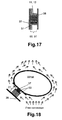
- thermopile 21 is made with corresponding increase of its thickness, the thickness being defined as the average distance in between the hot junction plane 24 and the cold junction plane 25 in the direction of average heat flow, without deterioration of its properties. Therefore, if commercially available thermopiles are used to build the thermopile unit 50 in accordance with embodiments of the present invention, these are preferably arranged into a multi-stage structure like the one shown in Figs. 16 , 17 so that the thermogenerator obeys the matching conditions (8) according to the present invention.
- Fig. 16 a 3-stage thermoelectric generator 49 according to embodiments of the present invention is shown, comprising 3 stacked thermopiles (21) or thermopile stages.
- thermopiles 21 results in an increased thickness of the thermoelectric generator 49, thus moving the cold plate 38 or the radiator 48 out of the air jet of free or forced convection around the heat source, and improving the Rayleigh or Reynolds number of the heat transfer at the surface of the cold plate (38) or at the surface of the radiator (48), resulting in an increase in power output.
- Fig. 17 shows a 3-stage thermoelectric generator 49 with thermal isolation 51 (e.g. a nano-porous material), for decreasing the parasitic heat transfer from the hot plate 37 and the thermopile unit 50 to the air.
- thermal isolation 51 e.g. a nano-porous material
- the multi-stage thermoelectric generator in accordance with embodiments of the present invention may further contain at least one spacer 52, 53 to further improve the Rayleigh/Reynolds number of the heat transfer at the surface of the cold plate (38) or at the surface of the radiator (48), thereby increasing the power production on cost of increased thickness of the TEG, Fig. 18 , 19 .
- thermopiles or other non-micromachined thermopiles are used in a TEG 49 in accordance with embodiments of the present invention
- the minimal voltage requirement may dominate over the requirement of maximal power.
- the overall outer TEG size and its total thickness are also frequently limiting boundary conditions for practical applications of the TEGs .
- the thermal mismatching of the TEG i.e. a certain deviation from the optimal power obtained according to the present invention, is acceptable to make the TEG output voltage acceptable for the accompanying electronics.
- the output power is a weak function of the number of thermocouples near the maximum output power, which corresponds to the condition of thermal matching as given in (8), i.e.
- thermocouples the condition where the number of thermocouples is such that the temperature difference over the thermopile 21 between the hot junction plane 24 and the cold junction plane 25 (which depends on the number of thermocouples) is equal to half of the temperature difference obtainable in the same embodiment with no thermocouples in it or with only one thermocouple leg in it.
- the temperature difference over the thermopile 21 is to be understood as the temperature difference over the multi-stage arrangement, between the hot junction plane 24 comprising the hottest junctions (closest to the hot plate 37) and the cold junction plane 25 comprising the coldest junctions (closest to the cold plate 38 or radiator 48).
- thermopile unit (50) the prior art matching condition wherein the temperature difference over the thermopile unit (50) is equal to half of the temperature difference between the heat source and the heat sink.
- the heat flow obtainable in prior art and one of the embodiments of the TEG in accordance with the present invention are evaluated and compared.
- the micromachined thermopiles as described by Infineon M. Strasser, R. Aigner, C. Lauterbach, T.F. Sturm, M. Franosch and G. Wachutka in "Micromachined CMOS Thermoelectric Generators as On-chip Power Supply", Transducers '03.
- thermopiles for human body applications fabricated in the past at Seiko ( M. Kishi, H. Nemoto, T. Hamao, M. Yamamoto, S. Sudou, M. Mandai and S.
- the matching conditions of embodiments of the present invention provide as a side effect a variation of the heat flow through an optimized thermopile unit by at least several tens of percent as compared to the same thermopile design with only 1 thermocouple leg or no thermocouples (numerical example is calculated below.).
- mismatching which has an adverse effect on the TEG power
- mismatched TEGs in accordance with embodiments of the present invention outperform prior art TEGs if the heat flow increases by e.g.
- thermocouples in the TEG as compared with the same TEG with no thermocouples in it or with only 1 thermocouple leg remaining.
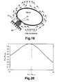
- the thermal matching curve is shown in Fig. 20 for the above example (Seiko).
- a small but distinct misalignment between the R th,tp / R th, air in corresponding to the maximum in the output power and the unity of R th,tp / R th, air in is observed.
- This small value of the misalignment is caused by the fact that a condition of the thermal matching in accordance with embodiments of the present invention, i.e., a significant variation of the heat flow, should be observed.
- thermopile types may be used, e.g. thermopiles on polymer substrate, micromachined thermopiles or membrane-type thermopiles.
- One or more effective rigid or flexible thermal isolation sheets 54 may furthermore be introduced to a garment 55 of homeotherms, e.g. human beings, as depicted in Fig. 22 as an example only, where the example on an arm is shown, while the garment 55 is shown as a dotted line.
- the thermal isolation sheets 54 thermally isolate the cold plate of the TEG 49 from the heat source and from the air jet of free or forced convection.
- the garment 55 itself can also serve as a thermal barrier.
- Such garment or isolation sheets may create larger thermal gradient per centimetre distance from the skin than occurs in the convective boundary layer.
- the total thickness of the TEG 49 required for reaching the low-temperature region of the boundary layer decreases and the overall thickness of the TEG 49, including the thickness of spacers in a direction of the heat flow, i.e. approximately normally to the skin surface, is reduced while still obeying the matching conditions in accordance with embodiments of the present invention.
- Proper positioning of the TEG 49 in the areas on a body of homeotherm where the boundary layer has the lower thickness may also help to decrease the required thickness of the TEG 49.
- Positioning the TEG 49 on areas of the body of a homeotherm proximal to the body inner organs referred to as a core of the body, e.g. the brain, may allow further increase of the generated power as has been found in experiments.
- the optimal position of the TEG 49 is on the temples of his head and on his forehead.
- the TEG 49 becomes effective also during nocturnal time, i.e. on a sleeping person.
- both temples preferably have to be provided with TEGs 49 in case one of them is positioned on the pillow and thus producing lower power.
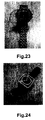
- Figs. 23, 24 photos of practical devices made in accordance with embodiments of the present invention are shown. The measured performance of these devices is reported in Figs. 25, 26 , showingthe open circuit voltage and the power as a function of air temperature.
- curve (1) refers to measurements on a person quietly sitting for a very long time (hours) with no intermediate activity
- curve (2) is obtained when a person performs usual office activity (walking in between offices, working on PC, etc.) in between the measurements, however, at least 5-10 minutes before the measurements, all activity is interrupted
- (3) is measured on a person walking indoor at about 4 km/hr.
- thermopiles for three types of thermopiles: for a commercially available thermopile and for two different micromachined thermopiles.
- the calculation of the commercially available thermopile is performed using an example of a bismuth telluride (BiTe) thermopile of a Seiko watch. It is assumed that the thermocouple legs are 0.6 mm long, their lateral size is 0.8 mm, and the area occupied by one leg cannot be less than 0.2 ⁇ 0.2 mm 2 , which can be considered as the state of the art in industrial technologies.
- the thermal resistance of the body is 440 cm 2 K/W in the location of the watch, the air temperature is 22 °C.
- thermopile chips of 2 x2 mm 2 each are used in the watch.
- the thermopile is not well suited for application on a human body, because the thermal resistance of the thermopile is mismatched to both the thermal resistance of the ambient air and to the thermal resistance of the body.
- the matching condition on state of the art approach cannot be reached, therefore a larger area of the chip is assumed, i.e. e.g. 1 x 1 cm 2 , which is to replace 10 smaller units used in the watch.
- thermocouples on the chip affording 11.8 ⁇ W power.
- the heat flow from the body changes by only 4% as compared with the case with no thermocouples in the TEG, or with only one thermocouple leg in it. If the conditions of matching in accordance with embodiments of the present invention are applied, 1620 thermocouples are needed for matching in accordance with embodiments of the invention.
- the TEG does not work efficiently and the heat flow from the body changes by only 4.5%. The effective TEG must induce significant change of the heat flow.
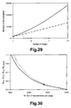
- the difference between the two matching conditions becomes clear from Fig. 27 , where the results of a 10-stage thermopile and the results for a one-stage thermopile are both plotted.
- the matching curves for 1 stage and 10 stages coincide with each other if expressed in function of ⁇ T tp / ⁇ T no,one leg (solid line).
- the heat flow through the TEG is shown as a dashed line for the 1-stage thermopile and as a dotted line for the 10-stage thermopile. In the latter case one can see large decrease of the heat flow W as compared with the case with no thermocouples or with 1 thermocouple leg W 0 , 1 .
- the matching point i.e., at the maximal power
- These prior art matching points do not reflect the true power optimum.
- thermopile under consideration is not well suited for a human body, as can be seen from the dashed heat flow curve, which does not show a large decrease near the matching point.
- a multi-stage arrangement to the contrary, gives a large and advantageous decrease of the heat flow, as can be seen from the dotted line.
- the number of thermocouples corresponding to the matching ( ⁇ ) in accordance with embodiments of the present invention offers maximum power, while the prior art matching does not.
- Fig. 28 The dependence of absolute power on the number of thermocouples per stage, calculated for the case of 1 stage-, 3 stage- and 6-stage thermopiles as above is shown in Fig. 28 as solid, dashed and dotted curves, respectively.
- the dashed straight line shows that the point when matching is reached shifts in the direction of increasing number of thermocouples per stage for increased number of stages. At 10 stages, the power increases more than 5 times as compared to a one-stage TEG.
- the different number of required thermocouples for a same number of stages reflects different matching conditions.
- Fig. 27 also suggests a useful range for a mismatching from the exact matching requirement in accordance with embodiments of the present invention, as already discussed above, marked with a horizontal arrow for a 10-stage thermopile. In this range, the generated power exceeds the one marked with (o) and corresponding to the prior art matching condition.
- Fig. 30 shows the ratio of the thermal resistance of the thermopile due to conductivity through the thermopile legs to the serial resistance composed mainly of the thermal resistance of the heat source and the heat sink (R th,tp / R amb - solid line), and the ratio of the thermal resistance of the thermopile to the parallel parasitic thermal resistance of the air in between the cold and hot plates (R th,tp / R th parasitic - dashed line).
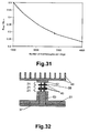
- Fig. 31 shows the ratio of the thermal resistance of the TEG to the serial resistance composed mainly of the thermal resistance of the heat source and the heat sink (R TEG / R amb ). In Figs.
- thermopile 30 , 31 the ratios are shown for a 10-stage thermopile with the optimal points in accordance with embodiments of the present invention ( ⁇ ) and according to prior art (o). It can easily be seen that the different matching conditions lead to quite different results, more particularly to quite different numbers of thermocouples per stage.
- thermopiles in particular the matching condition to be applied for calculation of the number of thermocouples required in the thermopile or thermopile stage, is especially dedicated to "difficult" sources of heat for energy scavenging, i.e. e.g. with very low thermal gradients and very high thermal resistance. Therefore, the case of the commercially available thermopile calculated above does not show all advantages of the methods and devices according to embodiments of the present invention. Micromachined thermopiles could be better suited for such applications. More in particular, thermopiles as in EP 1 612 870 but with a number of thermocouples calculated according to embodiments of the present invention can provide a good thermal matching to such kind of heat source.
- thermopile on a raised elongate structure 53 made according to EP 1 612 870 which is referred to herein as a spacer, is now considered.
- a three-stage TEG is shown in Fig. 32 , where the thermopile stages 21 are shown separated from each other for better understanding of the design.
- Two cases will be discussed: a thermopile well-optimised in accordance with embodiments of the present invention and a lower quality thermopile not optimised according to the present invention, e.g. optimized in accordance with the prior art. Then the effects or results will be compared. Differences between the different effects of the matching in accordance with embodiments of the present invention and multi-stage arrangement of the TEG in accordance with embodiments of the present invention will be made clear.
- thermopile made of bismuth telluride according to EP 1 612 870 is supposed to be placed on an artery with a body thermal resistance of 200 cm 2 K/W.
- the thermocouples are 5 ⁇ m tall with a lateral size of 1 ⁇ m.
- One thermocouple occupies 10 ⁇ 10 ⁇ m 2 area of the die on top of the spacer 53.
- the thermopile chip 45 of 1 x 1 cm 2 size is assumed to have a thickness of 1 mm and the material properties are again as in Table I.
- thermopile chips 45 are placed in between the hot plate 37 of 3 x 3 cm 2 size and the radiator 48 with fins or pins having 3 ⁇ 3 cm 2 size and an effective contact area to the air of 18 cm 2 due to fins or pins.
- the radiator 48 is placed at 1 cm distance from the hot plate 37 where the Rayleigh/Reynolds of the heat transfer at the surface of the cold plate (38) or at the surface of the radiator (48) numbers are increased due to decoupling them from the ones on the skin.
- the ambient air temperature is 22 °C.
- spacers 52, 53 may be necessary if the number of chips 45 is less than 10.
- each thermopile stage 21 has a number of, e.g. four, silicon pillars 56 of 10 x 10 ⁇ m 2 lateral size with 7440 K/W thermal resistance parallel to thermopiles, i.e. a parasitic thermal resistance.
- Fig. 33 solid line, shows the results of the modelling of a one-stage thermoelectric generator according to EP 1 612 870 .
- the circle, as before, shows the result of matching according to the prior art, and the triangle shows the result of matching in accordance with embodiments of the present invention, which is better with respect to power output, as can be appreciated from the graph of Fig. 33 .
- the effect of a multi-stage arrangement is shown for a 3 stage- and a 6-stage thermopile, by the dashed and dotted curves, respectively.
- FIGS. 27 show the zones where the matching in accordance with embodiments of the present invention shows an advantage over the prior art in case a larger or lesser voltage than at the matching point ( ⁇ ) is required, i.e. the degree of allowable mismatch in accordance with embodiments of the present invention.
- the multi-stage arrangement also offers better performance as compared to the one-stage thermoelectric generator according to EP 1 612 870 because the maximal power increases from about 120 ⁇ W to about 160 ⁇ W at the same size of the TEG embodiment.
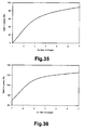
- Fig. 34 shows the gain in power due to the better matching in accordance with embodiments of the present invention, in function of the number of thermopile stages, as compared with prior art matching. It is shown that for a one-stage thermoelectric generator for which the number of thermocouples is calculated in accordance with the matching condition (8) of the present invention, the output power is about 70% higher than for a one-stage thermoelectric generator with the number of thermocouples calculated according to prior art matching. The gain in power decreases for an increasing number of stages, and amounts to about 20% for a 7-stage generator.
- Fig. 35 shows the gain in power for a multi-stage design according to embodiments of the present invention, as compared with a one-stage thermoelectric generator according to EP 1 612 870 , wherein the number of thermocouples is calculated according to prior art matching.
- Fig. 35 shows the effect of a multi-stage arrangement for prior-art thermoelectric generators. For the case considered here, the power generated by a two-stage thermoelectric generator is more than 30% higher than for a one-stage generator.
- the gain in power is about 90% as compared to a 1-stage generator.
- Fig. 36 is a sum of both effects shown in Figs. 34 and 35 , proving that the effects are independent, and summation with each other gives about 70% rise in power with a one-stage thermoelectric generator thermally matched according to the present invention and more than 2.2 times improvement in power for a 7-stage thermoelectric generator thermally matched according to the present invention, as compared with a 1-stage embodiment that is thermally matched according to the prior art.
- thermocouple legs are 3 ⁇ m long with a lateral size of 1 ⁇ m; one thermocouple leg occupies an area of 20 x 20 ⁇ m 2 on the chip surface.
- Thermocouples are made of polycrystalline silicon germanium with thermal conductivity of 0.03 W/ cm.K, electrical resistivity 2 m ⁇ .cm and a Seebeck coefficient of 0.1 mV/K.
- the shock protection and mechanical stiffness of the TEG 49 is provided with a polymer wall of 1 mm thick on the perimeter of the device connecting the hot and cold plates and encapsulating its inner volume, but making a parasitic thermal conductance of 658 K/W.
- Fig. 39 shows one more advantage of the matching in accordance with embodiments of the present invention for the case under consideration.
- the voltage also exceeds the prior art level V pa together with the power. It increases to about 140% as compared to the prior art at 7 stages, and it further increases up to two-fold improvement as compared to the prior art at 10 stages (extrapolation).
- one or more, and preferably all, inner surfaces of the TEG 49 may have low emissivity (lower than 20%, preferably lower than 10%) in the infrared region of the electromagnetic spectrum.
- low emissivity lower than 20%, preferably lower than 10%
- a number of metals may serve as low-emissivity materials.
- plastics or other materials used for forming the TEG 49 have high emissivity, they preferably are covered with highly reflecting (low emissivity) material, such as for example a metal.
- the inner surfaces of the TEG are the surfaces of the structures comprised in the TEG, in between the hot plate (37) and the cold plate (38) or the radiator (48).
- the inner volume of the TEG 49 as well as the volume on or in between the thermopile stages 21 (or in between chips 45, 46, if heat-spreading chips 46 are used) can be filled with a material showing lower thermal conductivity than the ambient, for example air, e.g. a microporous or nanoporous material.
- a material showing lower thermal conductivity than the ambient for example air, e.g. a microporous or nanoporous material.
- the inner surface of the radiator or of the cold plate preferably has a high emissivity (higher than 90%, preferably higher than 95%) in the wavelength range of thermal radiation (e.g. between 7 ⁇ m and 14 ⁇ m). Then, the inner surface of the hot plate 37 may have a low emissivity (lower than 20%, preferably lower than 10%) in the infrared region.
- a TEG 49 according to a further embodiment of the present invention is preferably provided with a shield or screen 60 with a low emissivity in the infrared region. The screen 60 may be installed in between and thermally isolated, for example by means of thermal isolation 51, from the hot plate 37 and the cold plate 38 or radiator 48. This is illustrated in Fig. 40 .
- the TEG 49 may also be used for outdoor applications at temperatures above body core temperature and with a radiant heat from sun or from ambient (e.g. in a desert when the sand is heated to e.g. about 40-90 °C)
- the TEG 49 may be used in reverse mode of operation, i.e. when the heat flow direction is from the ambient into a body, or to another surface, on which the device is mounted.
- the outer surface of the cold plate 38 or radiator 48 must have a low absorption in the visible and near-infrared spectral regions, but may still have a high emissivity in the far-infrared, where the radiator emits thermal radiation.
- the measured voltage generation on a practical device in reverse mode is illustrated in Fig. 25 at temperatures of 41-42 °C; the correspondingly generated power can be seen in Fig. 26 .
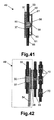
- Fig. 41 shows a cross-section of a possible implementation of a TEG 49 according to one of the embodiments of the present invention.
- the TEG 49 may be mounted as a "button” or a series of "buttons” in a garment 55 (like in EP 1 612 870 ), see also Fig. 22 .
- the separate units 49 may be interconnected electrically with each other.
- the hot plate 37 and the cold plate 38 or the radiator 48 can be made flexible for convenience of the wearer and also for decreasing the mechanical shocks when wearing the TEG 49 or during laundry of the garment 55.
- the hot plate 37 must preferably be larger than the outer size of the thermopile unit 50, the outer size of the thermopile unit 50 being determined in a plane parallel to the hot plate 37, preferably at least twice as large, more preferred at least three times as large, to satisfy the matching conditions in accordance with the present invention and to provide low thermal resistance of the air in between the TEG 49 and the skin in a standard case when the garment 55 is not tight.
- Tightening bands or threads preferably elastic tightening bands or threads, can optionally also be added to the clothes for better mechanical and therefore also better thermal contact to the skin.
- the shown example of the device contains thermally isolating pillars 61 or an encapsulating wall 61 on the perimeter of the cold plate 38.
- the inner volume in between the plates 37, 38, in embodiments of a TEG in accordance with the present invention can be, but does not need to be, completely filled with thermally isolating material other than air, e.g. a nanoporous material.
- thermally isolating material other than air e.g. a nanoporous material.
- a part of the inner volume may also be used for the accompanying electronic module for power conditioning, energy storage and other useful functions depending on specificity of the application, e.g. for sensor nodes.
- heat transferring structures 70 like in the example shown in Fig. 42 could be implemented in the layers of the cloth worn under/above the garment layer with the TEG 49.
- the device represents in this case two or more components separately fabricated in two or more pieces of the garment.
- the TEG 49 can be, of course, implemented into any of the garment layers.
- the quantity, size and spread of the heat transferring structures 70 in the cloth must guarantee proper thermal contacting with the TEG 49. This may mean not only a physical contact but also a small distance in between the heat transferring structures and the TEG 49, which still provides reasonable performance of the TEG 49.
- Magnetic clamping of the heat transferring structures 70 to the TEG 49 or between heat transferring structures 70 in different garment layers 55 can be implemented furthermore, similar to what is disclosed in EP 1 612 870 .
- the heat transferring structures 70 can be made of metal or any other suitable materials with high thermal conductivity, including flexible materials.
- the zones of the garment 55 where the heat transfer is needed may alternatively also be subject of locally introducing heat-conductive threads or yarns, e.g. metallic threads, instead of using heat transferring structures 70 as shown in Fig. 42 .
Priority Applications (3)
| Application Number | Priority Date | Filing Date | Title |
|---|---|---|---|
| AT07447010T ATE451723T1 (de) | 2007-02-12 | 2007-02-12 | Verfahren zur thermischen abstimmung eines thermoelektrischen generators auf eine wärmequelle mit hohem wärmewiderstand und so erhaltener thermoelektrischer generator |
| DE602007003677T DE602007003677D1 (de) | 2007-02-12 | 2007-02-12 | Verfahren zur thermischen Abstimmung eines thermoelektrischen Generators auf eine Wärmequelle mit hohem Wärmewiderstand und so erhaltener thermoelektrischer Generator |
| EP07447010A EP1970973B1 (de) | 2007-02-12 | 2007-02-12 | Verfahren zur thermischen Abstimmung eines thermoelektrischen Generators auf eine Wärmequelle mit hohem Wärmewiderstand und so erhaltener thermoelektrischer Generator |
Applications Claiming Priority (1)
| Application Number | Priority Date | Filing Date | Title |
|---|---|---|---|
| EP07447010A EP1970973B1 (de) | 2007-02-12 | 2007-02-12 | Verfahren zur thermischen Abstimmung eines thermoelektrischen Generators auf eine Wärmequelle mit hohem Wärmewiderstand und so erhaltener thermoelektrischer Generator |
Publications (2)
| Publication Number | Publication Date |
|---|---|
| EP1970973A1 true EP1970973A1 (de) | 2008-09-17 |
| EP1970973B1 EP1970973B1 (de) | 2009-12-09 |
Family
ID=38283554
Family Applications (1)
| Application Number | Title | Priority Date | Filing Date |
|---|---|---|---|
| EP07447010A Not-in-force EP1970973B1 (de) | 2007-02-12 | 2007-02-12 | Verfahren zur thermischen Abstimmung eines thermoelektrischen Generators auf eine Wärmequelle mit hohem Wärmewiderstand und so erhaltener thermoelektrischer Generator |
Country Status (3)
| Country | Link |
|---|---|
| EP (1) | EP1970973B1 (de) |
| AT (1) | ATE451723T1 (de) |
| DE (1) | DE602007003677D1 (de) |
Cited By (4)
| Publication number | Priority date | Publication date | Assignee | Title |
|---|---|---|---|---|
| DE102008054946A1 (de) * | 2008-12-19 | 2010-06-24 | Endress + Hauser Wetzer Gmbh + Co. Kg | Schutzgehäusevorrichtung für Feldgeräte mit thermoelektrischem Generator |
| EP2498310A2 (de) | 2011-03-11 | 2012-09-12 | Imec | Thermoelekrisches Textil |
| WO2017032821A1 (fr) * | 2015-08-27 | 2017-03-02 | Commissariat A L'energie Atomique Et Aux Energies Alternatives | Convertisseur thermoelectrique thermiquement transparent |
| CN112860031A (zh) * | 2021-03-05 | 2021-05-28 | 安徽科兴机电科技有限公司 | 一种计算机硬件热能收集转换装置 |
Citations (7)
| Publication number | Priority date | Publication date | Assignee | Title |
|---|---|---|---|---|
| EP1001470A1 (de) * | 1998-11-13 | 2000-05-17 | Seiko Instruments Inc. | Elektronische Anordnung mit thermoelektrischem Generator |
| US6075199A (en) * | 1998-04-29 | 2000-06-13 | National Research Council Of Canada | Body heat power generator |
| US6222114B1 (en) * | 1998-02-20 | 2001-04-24 | Seiko Instruments Inc. | Portable wrist device |
| EP1227375A1 (de) * | 2000-05-31 | 2002-07-31 | Citizen Watch Co. Ltd. | Uhr,die thermische energie erzeugt,und ihr boden |
| US6438964B1 (en) * | 2001-09-10 | 2002-08-27 | Percy Giblin | Thermoelectric heat pump appliance with carbon foam heat sink |
| EP1612870A1 (de) * | 2004-07-01 | 2006-01-04 | Interuniversitair Microelektronica Centrum Vzw | Verfahren zur Herstellung eines thermoelektrischen Generators und thermoelektrischer Generator dadurch erhalten |
| US20060243317A1 (en) * | 2003-12-11 | 2006-11-02 | Rama Venkatasubramanian | Thermoelectric generators for solar conversion and related systems and methods |
-
2007
- 2007-02-12 AT AT07447010T patent/ATE451723T1/de not_active IP Right Cessation
- 2007-02-12 DE DE602007003677T patent/DE602007003677D1/de active Active
- 2007-02-12 EP EP07447010A patent/EP1970973B1/de not_active Not-in-force
Patent Citations (7)
| Publication number | Priority date | Publication date | Assignee | Title |
|---|---|---|---|---|
| US6222114B1 (en) * | 1998-02-20 | 2001-04-24 | Seiko Instruments Inc. | Portable wrist device |
| US6075199A (en) * | 1998-04-29 | 2000-06-13 | National Research Council Of Canada | Body heat power generator |
| EP1001470A1 (de) * | 1998-11-13 | 2000-05-17 | Seiko Instruments Inc. | Elektronische Anordnung mit thermoelektrischem Generator |
| EP1227375A1 (de) * | 2000-05-31 | 2002-07-31 | Citizen Watch Co. Ltd. | Uhr,die thermische energie erzeugt,und ihr boden |
| US6438964B1 (en) * | 2001-09-10 | 2002-08-27 | Percy Giblin | Thermoelectric heat pump appliance with carbon foam heat sink |
| US20060243317A1 (en) * | 2003-12-11 | 2006-11-02 | Rama Venkatasubramanian | Thermoelectric generators for solar conversion and related systems and methods |
| EP1612870A1 (de) * | 2004-07-01 | 2006-01-04 | Interuniversitair Microelektronica Centrum Vzw | Verfahren zur Herstellung eines thermoelektrischen Generators und thermoelektrischer Generator dadurch erhalten |
Non-Patent Citations (4)
| Title |
|---|
| HASEBE S ET AL: "Polymer based smart flexible thermopile for power generation", MICRO ELECTRO MECHANICAL SYSTEMS, 2004. 17TH IEEE INTERNATIONAL CONFERENCE ON. (MEMS) MAASTRICHT, NETHERLANDS 25-29 JAN. 2004, PISCATAWAY, NJ, USA,IEEE, US, 25 January 2004 (2004-01-25), pages 689 - 692, XP010767983, ISBN: 0-7803-8265-X * |
| KISHI M ET AL: "Micro thermoelectric modules and their application to wristwatches as an energy source", EIGHTEENTH INTERNATIONAL CONFERENCE ON THERMOELECTRICS. PROCEEDINGS, ICT'99 (CAT. NO.99TH8407) IEEE PISCATAWAY, NJ, USA, 1999, pages 301 - 307, XP010379381, ISBN: 0-7803-5451-6 * |
| LEONOV V ET AL: "Thermoelectric mems generators as a power supply for a body area network", SOLID-STATE SENSORS, ACTUATORS AND MICROSYSTEMS, 2005. DIGEST OF TECHNICAL PAPERS. TRANSDUCERS '05. THE 13TH INTERNATIONAL CONFERENCE ON SEOUL, KOREA JUNE 5-9, 2005, PISCATAWAY, NJ, USA,IEEE, 5 June 2005 (2005-06-05), pages 291 - 294, XP010828018, ISBN: 0-7803-8994-8 * |
| TORFS, T ET AL: "BODY-HEAT POWERED AUTONOMOUS PULSE OXIMETER", IEEE SENSORS 2006 EXCO, 22 October 2006 (2006-10-22) - 25 October 2006 (2006-10-25), DAEGU KOREA, pages 427 - 430, XP002445434 * |
Cited By (5)
| Publication number | Priority date | Publication date | Assignee | Title |
|---|---|---|---|---|
| DE102008054946A1 (de) * | 2008-12-19 | 2010-06-24 | Endress + Hauser Wetzer Gmbh + Co. Kg | Schutzgehäusevorrichtung für Feldgeräte mit thermoelektrischem Generator |
| EP2498310A2 (de) | 2011-03-11 | 2012-09-12 | Imec | Thermoelekrisches Textil |
| WO2017032821A1 (fr) * | 2015-08-27 | 2017-03-02 | Commissariat A L'energie Atomique Et Aux Energies Alternatives | Convertisseur thermoelectrique thermiquement transparent |
| FR3040542A1 (fr) * | 2015-08-27 | 2017-03-03 | Commissariat Energie Atomique | Convertisseur thermoelectrique thermiquement transparent |
| CN112860031A (zh) * | 2021-03-05 | 2021-05-28 | 安徽科兴机电科技有限公司 | 一种计算机硬件热能收集转换装置 |
Also Published As
| Publication number | Publication date |
|---|---|
| DE602007003677D1 (de) | 2010-01-21 |
| ATE451723T1 (de) | 2009-12-15 |
| EP1970973B1 (de) | 2009-12-09 |
Similar Documents
| Publication | Publication Date | Title |
|---|---|---|
| US20080314429A1 (en) | Method for Thermal Matching of a Thermoelectric Generator with a Heat Source Having High Thermal Resistance and Thermoelectric Generator thus Obtained | |
| US7723606B2 (en) | Method of manufacturing a thermoelectric generator and thermoelectric generator thus obtained | |
| US7875791B2 (en) | Method for manufacturing a thermopile on a membrane and a membrane-less thermopile, the thermopile thus obtained and a thermoelectric generator comprising such thermopiles | |
| Nozariasbmarz et al. | High power density body heat energy harvesting | |
| Eom et al. | Flexible thermoelectric power generation system based on rigid inorganic bulk materials | |
| Qing et al. | Characteristics and parametric analysis of a novel flexible ink-based thermoelectric generator for human body sensor | |
| EP2333856B1 (de) | Thermoelektrischer Generator und Verfahren zur Erzeugung von Thermoelektrizität | |
| Jo et al. | Flexible thermoelectric generator for human body heat energy harvesting | |
| Leonov et al. | Theory and simulation of a thermally matched micromachined thermopile in a wearable energy harvester | |
| Ikechukwu et al. | Transient analysis of segmented Di-trapezoidal variable geometry thermoelement | |
| US20220013704A1 (en) | Flexible thermoelectric devices | |
| Francioso et al. | Wearable and flexible thermoelectric generator with enhanced package | |
| KR20110082420A (ko) | 초전 재료를 이용한 에너지 수확 장치 | |
| Leonov | Simulation of maximum power in the wearable thermoelectric generator with a small thermopile | |
| EP1970973B1 (de) | Verfahren zur thermischen Abstimmung eines thermoelektrischen Generators auf eine Wärmequelle mit hohem Wärmewiderstand und so erhaltener thermoelektrischer Generator | |
| WO2017059392A1 (en) | Flexible thermoelectric generator | |
| WO2013155181A1 (en) | Superlattice quantum well thermoelectric generator via radiation exchange and/or conduction/convection | |
| CN103460422A (zh) | 热偶发电器及其制造方法 | |
| EP2099079A1 (de) | Hybrider Energiesammler mit Thermosäuleneinheit und photovoltaischen Zellen | |
| JP2013033810A (ja) | 熱電変換モジュール | |
| Liang et al. | Structural design for wearable self-powered thermoelectric modules with efficient temperature difference utilization and high normalized maximum power density | |
| Contento et al. | Simultaneous materials and layout optimization of non-imaging optically concentrated solar thermoelectric generators | |
| Boughaleb et al. | Thermal modeling and optimization of a thermally matched energy harvester | |
| Bomberger et al. | Modeling passive power generation in a temporally-varying temperature environment via thermoelectrics | |
| Leonov et al. | Micromachined polycrystalline Si thermopiles in a T-shirt |
Legal Events
| Date | Code | Title | Description |
|---|---|---|---|
| PUAI | Public reference made under article 153(3) epc to a published international application that has entered the european phase |
Free format text: ORIGINAL CODE: 0009012 |
|
| 17P | Request for examination filed |
Effective date: 20071127 |
|
| AK | Designated contracting states |
Kind code of ref document: A1 Designated state(s): AT BE BG CH CY CZ DE DK EE ES FI FR GB GR HU IE IS IT LI LT LU LV MC NL PL PT RO SE SI SK TR |
|
| AKX | Designation fees paid |
Designated state(s): AT BE BG CH CY CZ DE DK EE ES FI FR GB GR HU IE IS IT LI LT LU LV MC NL PL PT RO SE SI SK TR |
|
| GRAP | Despatch of communication of intention to grant a patent |
Free format text: ORIGINAL CODE: EPIDOSNIGR1 |
|
| GRAS | Grant fee paid |
Free format text: ORIGINAL CODE: EPIDOSNIGR3 |
|
| GRAA | (expected) grant |
Free format text: ORIGINAL CODE: 0009210 |
|
| AK | Designated contracting states |
Kind code of ref document: B1 Designated state(s): AT BE BG CH CY CZ DE DK EE ES FI FR GB GR HU IE IS IT LI LT LU LV MC NL PL PT RO SE SI SK TR |
|
| REG | Reference to a national code |
Ref country code: GB Ref legal event code: FG4D |
|
| REG | Reference to a national code |
Ref country code: CH Ref legal event code: EP |
|
| REG | Reference to a national code |
Ref country code: IE Ref legal event code: FG4D |
|
| REF | Corresponds to: |
Ref document number: 602007003677 Country of ref document: DE Date of ref document: 20100121 Kind code of ref document: P |
|
| REG | Reference to a national code |
Ref country code: NL Ref legal event code: VDEP Effective date: 20091209 |
|
| PG25 | Lapsed in a contracting state [announced via postgrant information from national office to epo] |
Ref country code: SE Free format text: LAPSE BECAUSE OF FAILURE TO SUBMIT A TRANSLATION OF THE DESCRIPTION OR TO PAY THE FEE WITHIN THE PRESCRIBED TIME-LIMIT Effective date: 20091209 Ref country code: LT Free format text: LAPSE BECAUSE OF FAILURE TO SUBMIT A TRANSLATION OF THE DESCRIPTION OR TO PAY THE FEE WITHIN THE PRESCRIBED TIME-LIMIT Effective date: 20091209 Ref country code: FI Free format text: LAPSE BECAUSE OF FAILURE TO SUBMIT A TRANSLATION OF THE DESCRIPTION OR TO PAY THE FEE WITHIN THE PRESCRIBED TIME-LIMIT Effective date: 20091209 |
|
| RAP2 | Party data changed (patent owner data changed or rights of a patent transferred) |
Owner name: INTERUNIVERSITAIR MICROELEKTRONICA CENTRUM NEDERLA |
|
| LTIE | Lt: invalidation of european patent or patent extension |
Effective date: 20091209 |
|
| PG25 | Lapsed in a contracting state [announced via postgrant information from national office to epo] |
Ref country code: SI Free format text: LAPSE BECAUSE OF FAILURE TO SUBMIT A TRANSLATION OF THE DESCRIPTION OR TO PAY THE FEE WITHIN THE PRESCRIBED TIME-LIMIT Effective date: 20091209 Ref country code: PL Free format text: LAPSE BECAUSE OF FAILURE TO SUBMIT A TRANSLATION OF THE DESCRIPTION OR TO PAY THE FEE WITHIN THE PRESCRIBED TIME-LIMIT Effective date: 20091209 Ref country code: LV Free format text: LAPSE BECAUSE OF FAILURE TO SUBMIT A TRANSLATION OF THE DESCRIPTION OR TO PAY THE FEE WITHIN THE PRESCRIBED TIME-LIMIT Effective date: 20091209 |
|
| PG25 | Lapsed in a contracting state [announced via postgrant information from national office to epo] |
Ref country code: AT Free format text: LAPSE BECAUSE OF FAILURE TO SUBMIT A TRANSLATION OF THE DESCRIPTION OR TO PAY THE FEE WITHIN THE PRESCRIBED TIME-LIMIT Effective date: 20091209 |
|
| REG | Reference to a national code |
Ref country code: GB Ref legal event code: S117 Free format text: REQUEST FILED; REQUEST FOR CORRECTION UNDER SECTION 117 FILED ON 2 JUNE 2010 |
|
| PG25 | Lapsed in a contracting state [announced via postgrant information from national office to epo] |
Ref country code: BG Free format text: LAPSE BECAUSE OF FAILURE TO SUBMIT A TRANSLATION OF THE DESCRIPTION OR TO PAY THE FEE WITHIN THE PRESCRIBED TIME-LIMIT Effective date: 20100309 Ref country code: NL Free format text: LAPSE BECAUSE OF FAILURE TO SUBMIT A TRANSLATION OF THE DESCRIPTION OR TO PAY THE FEE WITHIN THE PRESCRIBED TIME-LIMIT Effective date: 20091209 Ref country code: ES Free format text: LAPSE BECAUSE OF FAILURE TO SUBMIT A TRANSLATION OF THE DESCRIPTION OR TO PAY THE FEE WITHIN THE PRESCRIBED TIME-LIMIT Effective date: 20100320 Ref country code: IS Free format text: LAPSE BECAUSE OF FAILURE TO SUBMIT A TRANSLATION OF THE DESCRIPTION OR TO PAY THE FEE WITHIN THE PRESCRIBED TIME-LIMIT Effective date: 20100409 Ref country code: RO Free format text: LAPSE BECAUSE OF FAILURE TO SUBMIT A TRANSLATION OF THE DESCRIPTION OR TO PAY THE FEE WITHIN THE PRESCRIBED TIME-LIMIT Effective date: 20091209 Ref country code: PT Free format text: LAPSE BECAUSE OF FAILURE TO SUBMIT A TRANSLATION OF THE DESCRIPTION OR TO PAY THE FEE WITHIN THE PRESCRIBED TIME-LIMIT Effective date: 20100409 Ref country code: EE Free format text: LAPSE BECAUSE OF FAILURE TO SUBMIT A TRANSLATION OF THE DESCRIPTION OR TO PAY THE FEE WITHIN THE PRESCRIBED TIME-LIMIT Effective date: 20091209 |
|
| REG | Reference to a national code |
Ref country code: FR Ref legal event code: CD Ref country code: FR Ref legal event code: CA |
|
| PG25 | Lapsed in a contracting state [announced via postgrant information from national office to epo] |
Ref country code: SK Free format text: LAPSE BECAUSE OF FAILURE TO SUBMIT A TRANSLATION OF THE DESCRIPTION OR TO PAY THE FEE WITHIN THE PRESCRIBED TIME-LIMIT Effective date: 20091209 Ref country code: BE Free format text: LAPSE BECAUSE OF FAILURE TO SUBMIT A TRANSLATION OF THE DESCRIPTION OR TO PAY THE FEE WITHIN THE PRESCRIBED TIME-LIMIT Effective date: 20091209 Ref country code: CZ Free format text: LAPSE BECAUSE OF FAILURE TO SUBMIT A TRANSLATION OF THE DESCRIPTION OR TO PAY THE FEE WITHIN THE PRESCRIBED TIME-LIMIT Effective date: 20091209 |
|
| PLBE | No opposition filed within time limit |
Free format text: ORIGINAL CODE: 0009261 |
|
| STAA | Information on the status of an ep patent application or granted ep patent |
Free format text: STATUS: NO OPPOSITION FILED WITHIN TIME LIMIT |
|
| PG25 | Lapsed in a contracting state [announced via postgrant information from national office to epo] |
Ref country code: GR Free format text: LAPSE BECAUSE OF FAILURE TO SUBMIT A TRANSLATION OF THE DESCRIPTION OR TO PAY THE FEE WITHIN THE PRESCRIBED TIME-LIMIT Effective date: 20100310 Ref country code: MC Free format text: LAPSE BECAUSE OF NON-PAYMENT OF DUE FEES Effective date: 20100301 Ref country code: CY Free format text: LAPSE BECAUSE OF FAILURE TO SUBMIT A TRANSLATION OF THE DESCRIPTION OR TO PAY THE FEE WITHIN THE PRESCRIBED TIME-LIMIT Effective date: 20091209 |
|
| 26N | No opposition filed |
Effective date: 20100910 |
|
| PG25 | Lapsed in a contracting state [announced via postgrant information from national office to epo] |
Ref country code: IE Free format text: LAPSE BECAUSE OF NON-PAYMENT OF DUE FEES Effective date: 20100212 Ref country code: DK Free format text: LAPSE BECAUSE OF FAILURE TO SUBMIT A TRANSLATION OF THE DESCRIPTION OR TO PAY THE FEE WITHIN THE PRESCRIBED TIME-LIMIT Effective date: 20091209 |
|
| PG25 | Lapsed in a contracting state [announced via postgrant information from national office to epo] |
Ref country code: IT Free format text: LAPSE BECAUSE OF FAILURE TO SUBMIT A TRANSLATION OF THE DESCRIPTION OR TO PAY THE FEE WITHIN THE PRESCRIBED TIME-LIMIT Effective date: 20091209 |
|
| REG | Reference to a national code |
Ref country code: GB Ref legal event code: S117 Free format text: CORRECTIONS ALLOWED; REQUEST FOR CORRECTION UNDER SECTION 117 FILED ON 2 JUNE 2010 ALLOWED ON 21 JULY 2011 |
|
| REG | Reference to a national code |
Ref country code: CH Ref legal event code: PL |
|
| PG25 | Lapsed in a contracting state [announced via postgrant information from national office to epo] |
Ref country code: CH Free format text: LAPSE BECAUSE OF NON-PAYMENT OF DUE FEES Effective date: 20110228 Ref country code: LI Free format text: LAPSE BECAUSE OF NON-PAYMENT OF DUE FEES Effective date: 20110228 |
|
| PG25 | Lapsed in a contracting state [announced via postgrant information from national office to epo] |
Ref country code: HU Free format text: LAPSE BECAUSE OF FAILURE TO SUBMIT A TRANSLATION OF THE DESCRIPTION OR TO PAY THE FEE WITHIN THE PRESCRIBED TIME-LIMIT Effective date: 20100610 Ref country code: LU Free format text: LAPSE BECAUSE OF NON-PAYMENT OF DUE FEES Effective date: 20100212 |
|
| PG25 | Lapsed in a contracting state [announced via postgrant information from national office to epo] |
Ref country code: TR Free format text: LAPSE BECAUSE OF FAILURE TO SUBMIT A TRANSLATION OF THE DESCRIPTION OR TO PAY THE FEE WITHIN THE PRESCRIBED TIME-LIMIT Effective date: 20091209 |
|
| PGFP | Annual fee paid to national office [announced via postgrant information from national office to epo] |
Ref country code: DE Payment date: 20130124 Year of fee payment: 7 Ref country code: FR Payment date: 20130408 Year of fee payment: 7 Ref country code: GB Payment date: 20130129 Year of fee payment: 7 |
|
| REG | Reference to a national code |
Ref country code: DE Ref legal event code: R119 Ref document number: 602007003677 Country of ref document: DE |
|
| GBPC | Gb: european patent ceased through non-payment of renewal fee |
Effective date: 20140212 |
|
| REG | Reference to a national code |
Ref country code: FR Ref legal event code: ST Effective date: 20141031 |
|
| REG | Reference to a national code |
Ref country code: DE Ref legal event code: R119 Ref document number: 602007003677 Country of ref document: DE Effective date: 20140902 |
|
| PG25 | Lapsed in a contracting state [announced via postgrant information from national office to epo] |
Ref country code: GB Free format text: LAPSE BECAUSE OF NON-PAYMENT OF DUE FEES Effective date: 20140212 Ref country code: DE Free format text: LAPSE BECAUSE OF NON-PAYMENT OF DUE FEES Effective date: 20140902 Ref country code: FR Free format text: LAPSE BECAUSE OF NON-PAYMENT OF DUE FEES Effective date: 20140228 |